Article

Ignition of A Plasma Discharge Inside An Electrodeless Chamber: Methods and Characteristics

Electrical & Computer Engineering Department, Old Dominion University, Norfolk, VA 23529, USA
Plasma 2019, 2(4), 380-386; https://doi.org/10.3390/plasma2040030
Submission received: 31 July 2019 / Revised: 12 September 2019 / Accepted: 8 October 2019 / Published: 14 October 2019
(This article belongs to the Special Issue Low Temperature Plasma Jets: Physics, Diagnostics and Applications)

Abstract

:
In this paper the generation and diagnostics of a reduced pressure (300 mTorr to 3 Torr) plasma generated inside an electrodeless containment vessel/chamber are presented. The plasma is ignited by a guided ionization wave emitted by a low temperature pulsed plasma jet. The diagnostics techniques include Intensified Charge Coupled Device (ICCD) imaging, emission spectroscopy, and Langmuir probe. The reduced-pressure discharge parameters measured are the magnitude of the electric field, the plasma electron number density and temperature, and discharge expansion speed.

1. Introduction

Low temperature plasma jets exhibit large electric fields at the tip of their plasma plumes. The magnitude of this field was measured by several investigators and was found to be in the 10–30 kV/cm range [1,2,3,4]. Figure 1 shows measurements of the electric field reported by Begum et al. [1] while Figure 2 shows simulation results reported by Naidis [5]. When impinging on a dielectric material, the plasma plume causes charge build up on the surface of the dielectric surface. Therefore, via capacitive coupling, the electric field can be effectively transmitted to the area behind the dielectric barrier [6,7,8]. Under reduced pressure, the transmitted field can be large enough to start a discharge, which quickly propagates and grows in volume [9].
In this paper the characteristics of the plasma ignited inside an electrodeless dielectric chamber by an external plasma jet are reported. The chamber has no direct physical or electric connections to the externally applied plasma jet. The diagnostics techniques used, which include emission spectroscopy, fast imaging, and Langmuir probe, allow for the measurement of the magnitude of the transmitted electric field inside the chamber, the plasma electron number density and temperature, and discharge propagation speed.

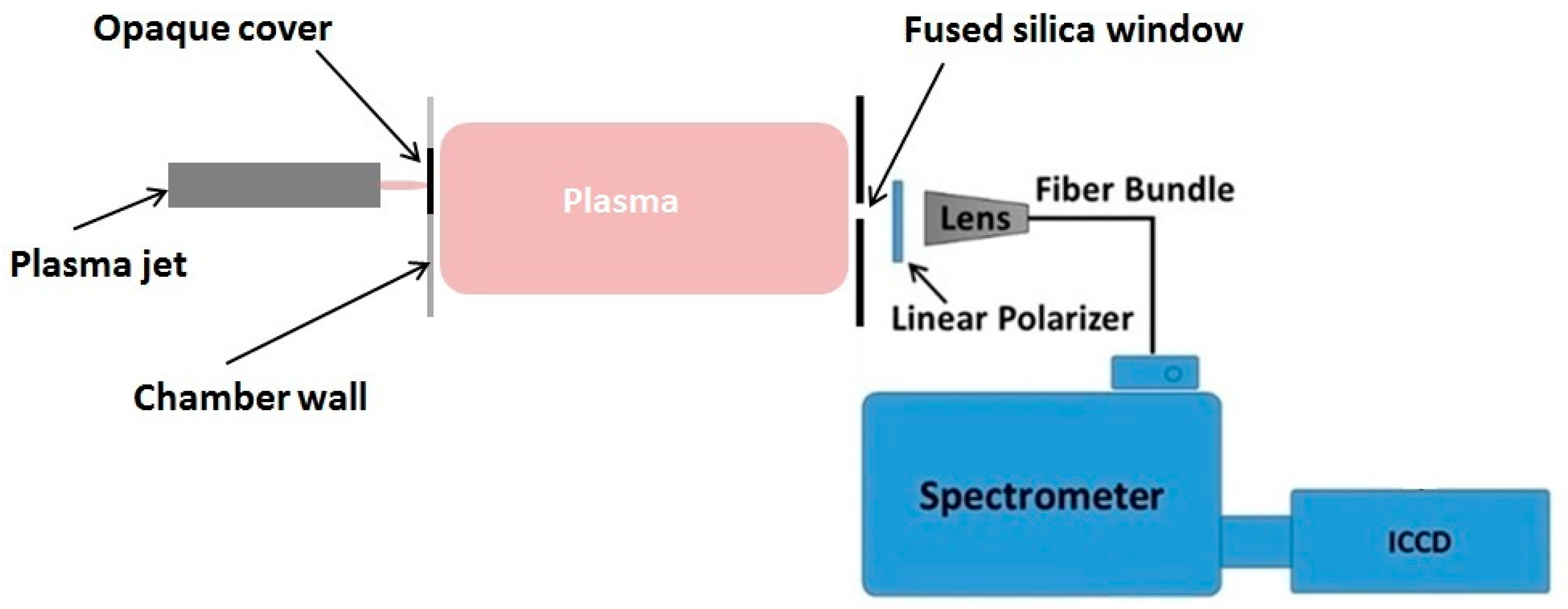
2. Materials and Methods

Low temperature plasma jets launched in the ambient environment are enabled by guided ionization waves [10]. The electric field at the front of these waves can be quite large and can be transmitted across a dielectric barrier. If the dielectric barrier constitutes the wall of a chamber where the pressure can be controlled, then a diffuse plasma can be generated inside the chamber below a certain pressure threshold [9]. This principle was used here to generate a reduced pressure plasma inside a Pyrex cross-shaped tube that has no electrodes or electrical connections. Figure 3 shows the experimental setup and a photo of the reduced pressure plasma inside the Pyrex tubing.
The tubing/chamber is made of Pyrex glass, where the pressure can be reduced gradually down to the mTorr range. The plasma jet is physically independent of the chamber and is applied externally. It is driven by repetitive narrow pulses (ns–µs) with magnitudes in the kV range. The tip of the plasma plume is brought against the external wall of the chamber to ignite a plasma at reduced pressure.

3. Results and Discussion

For all the experiments described below, the pulsed power supply and its associated circuitry were all placed inside a Faraday cage located in a separate location, away from the chamber and the diagnostics equipment, and all cables were properly shielded. All spectroscopic and Langmuir probe measurements presented here reflect average values. No time- and space-resolved measurements are reported. In addition, in order to have a ground reference for the diagnostics circuitry, a thin copper ring was wrapped around one arm of the Pyrex chamber (externally) and connected to a hard ground. For all experiments, the jet was driven by the following parameters, unless otherwise mentioned: Voltage was 7 kV, pulse width was 1 µs, repetition rate was 7 kHz, and helium flow rate was 7 slm.

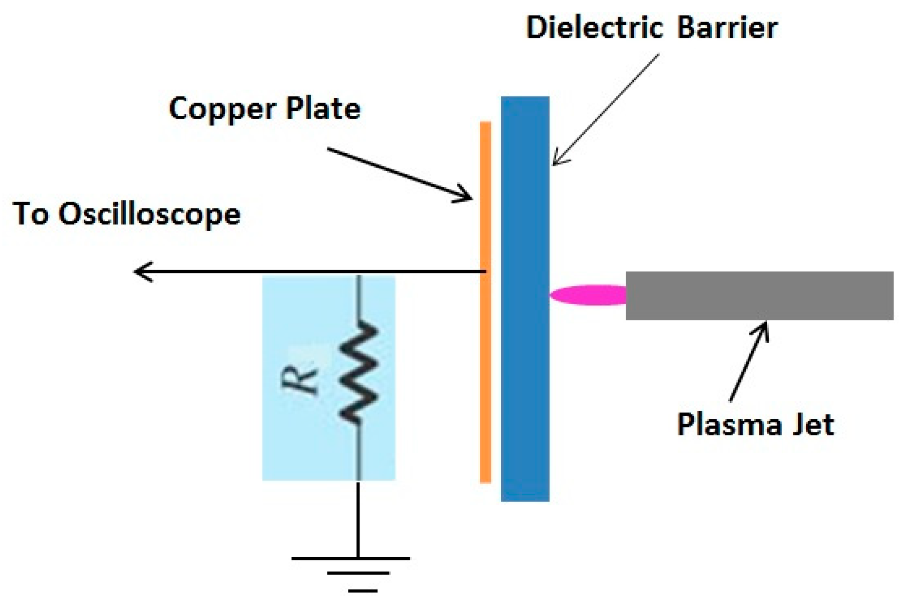
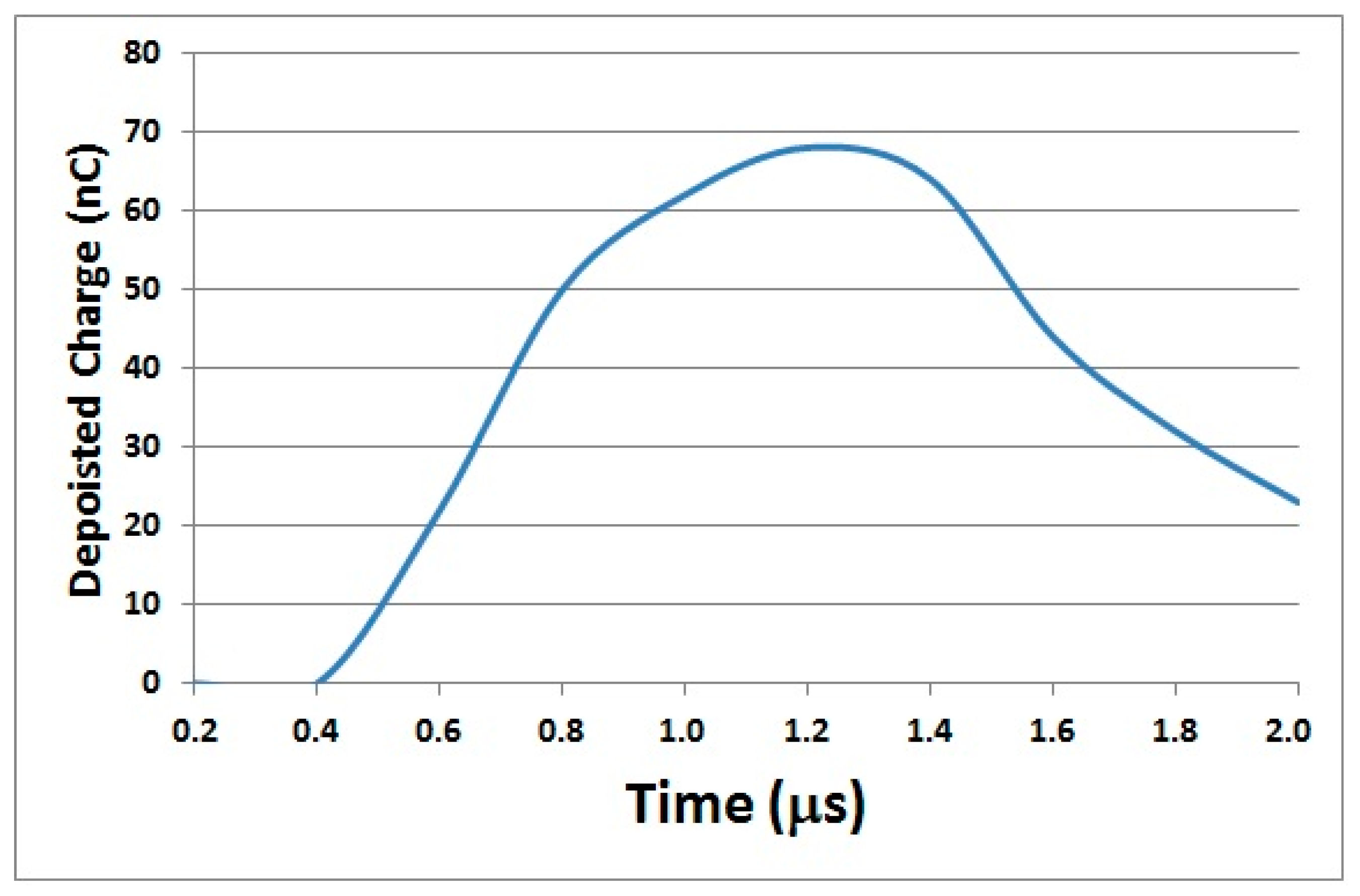
3.1. Measurement of the Deposited Charge

The electric field generated behind a dielectric barrier is a function of the amount of charges deposited on the outer/opposite surface of the dielectric. To measure the charges deposited on the surface of a dielectric surface by the plume of a plasma jet, the following circuit was used (Figure 4) [11]. The charge was calculated by integrating the current flowing through the readout resistor. The current through the resistor flowed via capacitive coupling, with the capacitance having the dielectric constant of the Pyrex glass, and the area was that of the copper plate electrode placed against the dielectric.
Figure 5 is a plot of the deposited charges versus time when the plasma jet is powered by 1 µs wide pulses of magnitude of 7 kV.
The magnitude of the electric field generated by such charge accumulation was estimated to be in the 10–15 kV/cm range for a dielectric thickness of about 1.5 cm. This is in relative agreement with the spectroscopic measurements presented in the next section.

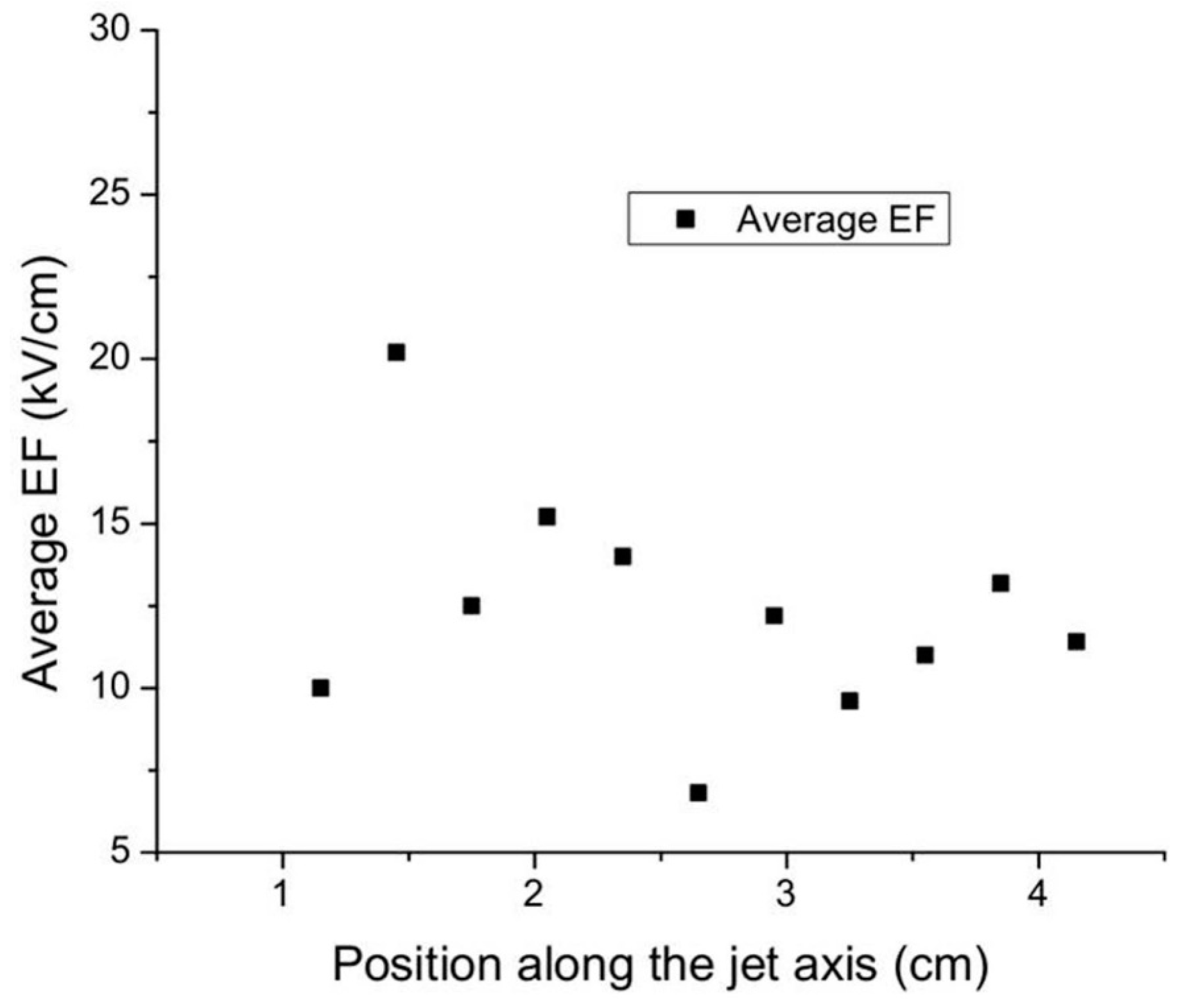
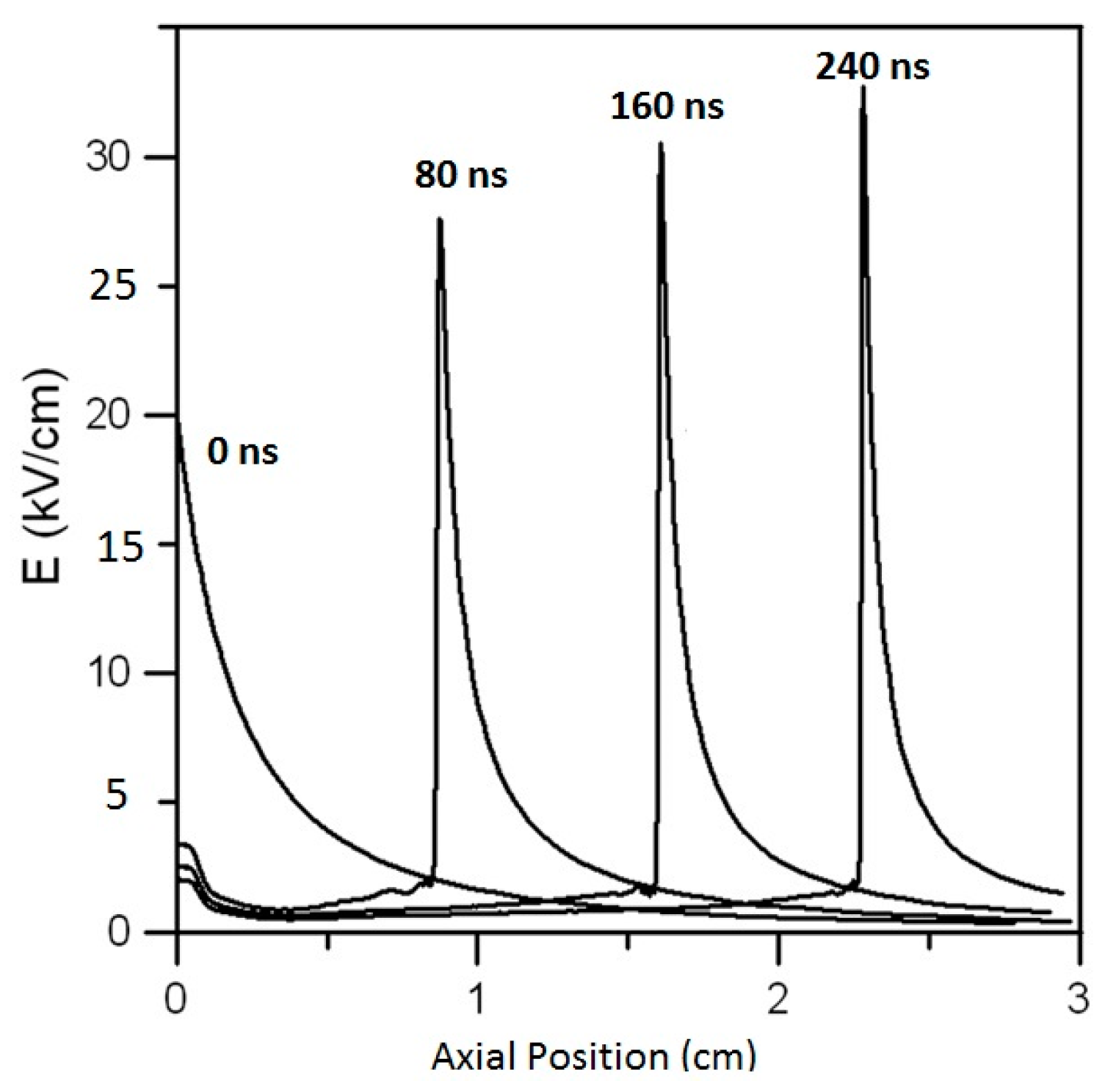
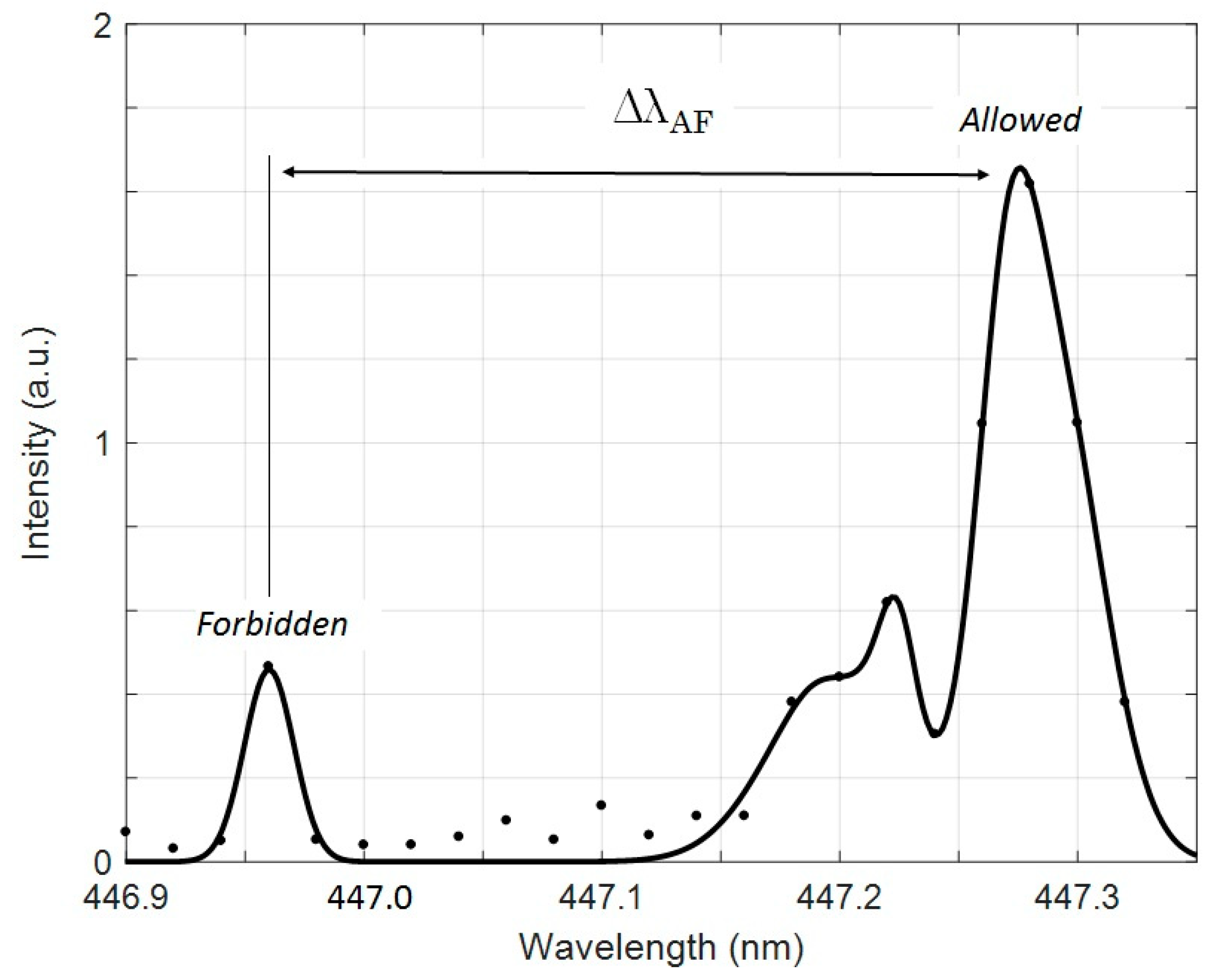
3.2. Measurement of the Transmitted Electric Field

The electric field was measured using the Stark splitting and shifting of the helium visible lines and their forbidden lines. The displacement of the Stark sublevels of He I 447.1 nm and its forbidden component was calculated. The wavelength separation (Δλallowed-forbidden) of the π components of allowed and forbidden lines (mupper = 0 to mlower = 0) was measured and its relationship to the electric field strength was used to calculate E using a polynomial relation [12,13] (see Equation (1)). Using this method, electric field strength up to 18 kV/cm was calculated [11]. Figure 6 shows the experimental setup while Figure 7 shows a result of such a measurement.
Δλallowed-forbidden = −1.6 × 10⁻⁵ × E3 + 5.95 × 10⁻⁴ × E2 + 2.5 × 10⁻⁴ × E + 0.15,
where E is expressed in kV/cm.

3.3. Measurement of the Electrons Density and Temperature

A Langmuir probe was used to measure the electrons density and temperature of the plasma discharge inside the chamber. It is important to note again that only time-averaged values were measured. The measurements presented here are preliminary and only meant to give an approximate idea on the order of magnitude of the density and temperature. The probe was made of a shielded 5 mm long metal needle with a surface area of 2.36 mm2. A variable DC power supply was used to bias the probe. For an air plasma at a pressure of 400 mTorr, the average electron density was found to be around 1.6 × 1010 cm−3 and the average electron temperature was 2.2 eV. For a helium plasma, with a small admixture of air, at a pressure of 300 mTorr, the electron density was around 6.4 × 1010 cm−3 and the average temperature was 2.7 eV.

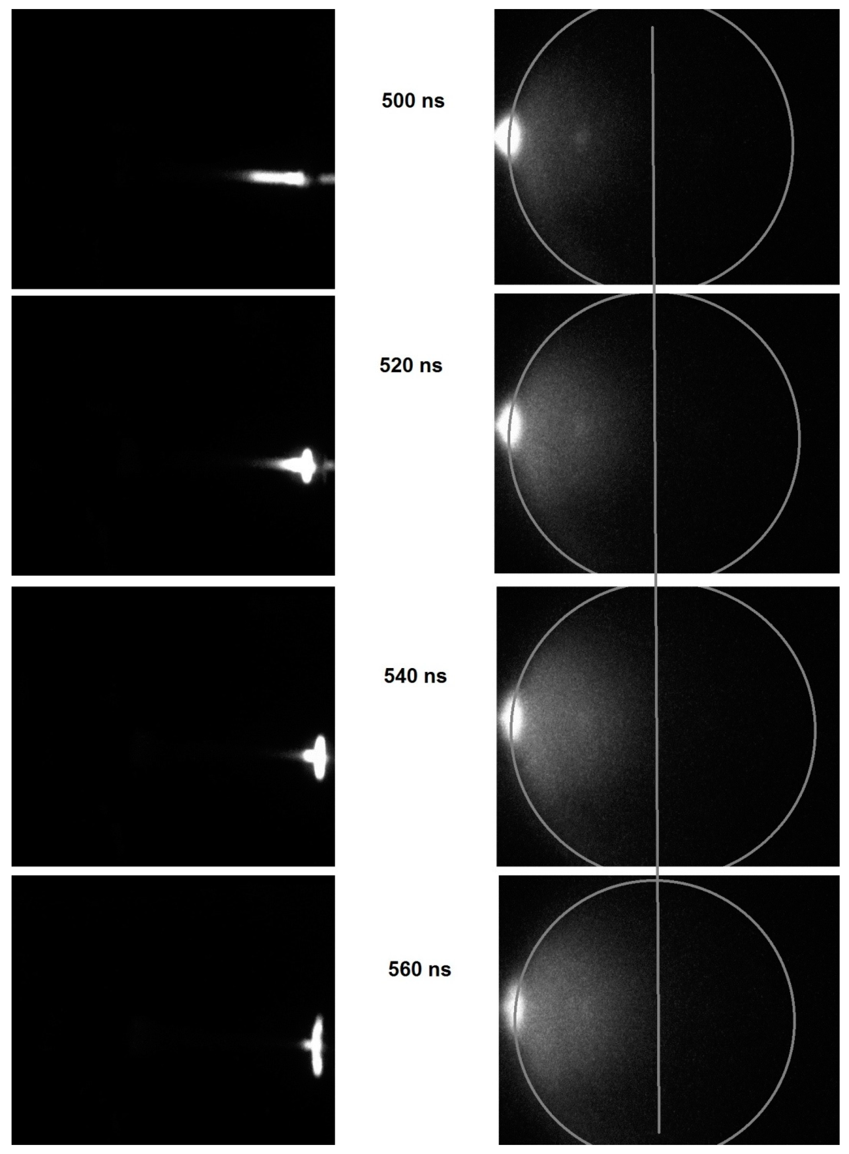
3.4. Dynamics of the Plasma Ignition Inside the Chamber

ICCD images of the expansion of the diffuse plasma inside the chamber, taken 20 nanoseconds apart, are shown in Figure 8 (using a Dicam Pro ICCD). The images show that, as the ionization wave front (i.e., plasma bullet) impinged on the outer surface of the chamber, a discharge was ignited behind the Pyrex glass wall. A glowing and expanding plasma advanced radially in all directions inside the chamber. The speed of expansion was estimated to be in the 106–107 cm/s range, consistent with that of an ionization wave in gases at low pressure.

4. Conclusions

Reduced pressure diffuse plasma can be generated inside a chamber having dielectric walls using an externally applied ionization wave emitted by a plasma jet. The chamber had no electrodes or any electrical connection. The dynamics of the diffuse plasma was elucidated using ICCD images, the electric field transmitted inside the chamber was measured using a spectroscopic technique, and the electron density and temperature were measured by a Langmuir probe. The advantage of the generation method discussed in this paper is that the plasma inside the chamber is free of metal contamination (since there are no electrodes). Such plasma can be very useful for material processing. Most low-pressure RF plasmas (capacitively or inductively coupled) require impedance matching when operated at high power. However, the new method described in this paper does not need an impedance matching module since the plasma jet is electrically independent of the reduced pressure plasma chamber. It only serves as the source of the ionization wave. Therefore, the plasma inside the chamber may be characterized as a ”remotely” generated plasma.

Conflicts of Interest

The author declares no conflict of interest.

References

  1. Begum, A.; Laroussi, M.; Pervez, M.R. Atmospheric pressure helium/air plasma jet: Breakdown processes and propagation phenomenon. AIP Adv. 2013, 3, 062117. [Google Scholar] [CrossRef]
  2. Sobota, A.; Guaitella, O.; Garcia-Caurel, E. Experimentally obtained values of electric field of an atmospheric pressure plasma jet impinging on a dielectric surface. J. Phys. D Appl. Phys. 2013, 46, 37. [Google Scholar] [CrossRef]
  3. Stretenovic, G.B.; Krstic, I.B.; Kovacevic, V.V.; Obradovic, A.M.; Kuraica, M.M. Spatio-temporally resolved electric field measurements in helium plasma jet. J. Phys. D Appl. Phys. 2014, 47, 10. [Google Scholar]
  4. Robert, E.; Darny, T.; Dozias, S.; Iseni, S.; Pouvesle, J.-M. New insights on the propagation of pulsed atmospheric plasma streams: From single jet to multi jet arrays. Phys. Plasmas 2015, 22, 122007. [Google Scholar] [CrossRef]
  5. Naidis, G.V. Modeling of Streamer Propagation in Atmospheric Pressure Helium Plasma Jets. J. Phys. D Appl. Phys. 2010, 43, 40. [Google Scholar] [CrossRef]
  6. Lu, X.; Xiong, Q.; Xiong, Z.; Hu, J.; Zhou, F.; Gong, W.; Xian, Y.; Zou, C.; Tang, Z.; Jiang, Z.; et al. Propagation of an atmospheric pressure plasma plume. J. Appl. Phys. 2009, 105, 043304. [Google Scholar] [CrossRef]
  7. Xiong, Z.; Robert, E.; Sarron, V.; Pouvesle, J.-M.; Kushner, M.J. Atmospheric-pressure plasma transfer across dielectric channels and tubes. J. Phys. D Appl. Phys. 2013, 46, 15. [Google Scholar] [CrossRef]
  8. Guaitella, O.; Sobota, A. The impingement of a kHz helium atmospheric pressure plasma jet on a dielectric surface. J. Phys. D Appl. Phys. 2015, 48, 25. [Google Scholar] [CrossRef]
  9. Laroussi, M.; Razavi, H. Indirect Generation of a Large Volume Diffuse Plasma by an Ionization Wave from a Plasma Jet. IEEE Trans. Plasma Sci. 2015, 43, 2226–2229. [Google Scholar] [CrossRef]
  10. Lu, X.; Naidis, G.V.; Laroussi, M.; Ostrikov, K. Guided Ionization Waves: Theory and Experiments. Phys. Rep. 2014, 540, 123–166. [Google Scholar] [CrossRef]
  11. Razavi, H.; Laroussi, M. Diagnostics of Diffuse Large Volume Plasma Generated by an External Ionization Waves. In Proceedings of the Gaseous Electronics Conference, Pittsburg, PA, USA, 6–10 November 2017; p. 42. [Google Scholar]
  12. Kuraica, M.M.; Konjevic, N. Electric field measurement in the cathode fall region of a glow discharge in helium. Appl. Phys. Lett. 1997, 70, 1521. [Google Scholar] [CrossRef]
  13. Lu, Y.; Wu, S.; Cheng, W.; Lu, X. Electric field measurements in an atmospheric-pressure microplasma jet using Stark polarization emission spectroscopy of helium atom. Eur. Phys. J. Spec. Top. 2017, 226, 2979–2989. [Google Scholar] [CrossRef]
Figure 1. Mean magnitude of the electric field along the axis for a plasma plume emitted by a pulsed plasma jet [1].
Plasma 02 00030 g001
Figure 2. Electric field axial profile at different times for a helium plasma jet emerging into surrounding air. The jet radius is 0.25 cm. Figure adapted from Figure 1 of [5].
Plasma 02 00030 g002
Figure 3. Schematic of the experimental setup (top) and photo of the large volume plasma inside the tubing/chamber (bottom). The plasma jet is applied externally on the far side of the chamber. The chamber is a Pyrex glass cross with an arm 18 inches long (inner diameter is 6 inches) and a second arm 16 inches long (inner diameter is 4 inches). For this photo, the pressure inside the chamber was 3 Torr and the gas was air.
Plasma 02 00030 g003aPlasma 02 00030 g003b
Figure 4. Circuit used to measure the amount of charge deposited on the surface of a dielectric. Copper plate was 1.5 inches × 1.5 inches thick. Dielectric plate was 2 inches × 2 inches and 0.6 inches thick. Resistance was 1 kΩ.
Plasma 02 00030 g004
Figure 5. Deposited charge as a function of time for pulse 1 µs wide, magnitude of 7 kV, pulse frequency of 7 kHz, and helium flow rate of 7 slm.
Plasma 02 00030 g005
Figure 6. Sketch of the experimental setup to measure the electric field in the chamber. The electric field in the bulk of the plasma is assumed to be weak so the radiation collected to measure the axial electric field in the chamber gives a measure of the field close to the chamber wall (opposite side to where the jet impinges on the wall), where the field is high. The spectrometer was a 0.5 m Spectra-Pro-500i imaging spectrometer (Acton Research). The grating was 3600 g/mm, the slit width was 300 µm, and the spectral resolution was set at 0.02 nm. ICCD was a Dicam-Pro. The pressure inside the chamber was 1.5 Torr and the gas was helium. For each wavelength, more than a million ICCD images were integrated over a collection time of 100 ms.
Plasma 02 00030 g006
Figure 7. Electric field (EF) measurement using Stark splitting. An EF average strength of about 18 kV/cm was measured.
Plasma 02 00030 g007
Figure 8. ICCD images of the plasma bullet (left panel) and of the expanding discharge inside the Pyrex tubing/chamber (right panel). The air pressure in the chamber was around 1 Torr. The contour of the chamber wall (grey circle) is added for illustrative purposes. The vertical line is added as a reference to better visualize the expansion of reduced pressure plasma. The images on the left panel show the plasma bullet arriving and spreading over the outer surface of the Pyrex glass wall.
Plasma 02 00030 g008

