Article

Design of a Chemical-Reaction Ceramic Paste, from Electric Arc Furnace Steel Slag and Potassium Hydrophosphate, for Applications in Monolithic Objects


by
Carlos Andres Cardenas Balaguera
1,
Andres Felipe Rubiano-Navarrete
2,*,
Pilar Astrid Ramos Casas
3 and
Lina Paola Espitia López
4
1
Grupo de Investigación INTERFAZ, Facultad de Ingenierias Fisicomecanicas, Universidad Industrial de Santander UIS, Carrera 27 #09 Ciudad Universitaria; Bucaramanga 680001, Colombia
2
Grupo de Investigación en Diseño, Innovación y Asistencia Técnica de Materiales Avanzados-DITMAV, Doctorado en Ingeniería y Ciencia de los Materiales, Universidad Pedagógica y Tecnológica de Colombia—UPTC, Tunja 150003, Colombia
3
Grupo de Investigación en Diseño, Innovación y Asistencia Técnica de Materiales Avanzados-DITMAV, Maestria en Metalurgia y Ciencia de los Materiales, Universidad Pedagógica y Tecnológica de Colombia UPTC, Tunja 150003, Colombia
4
Grupo de Investigación en Diseño, Innovación y Asistencia Técnica de Materiales Avanzados-DITMAV, Doctorado en Administración para la Sostenibilidad, Universidad Pedagógica y Tecnológica de Colombia UPTC, Tunja 150003, Colombia
*
Author to whom correspondence should be addressed.
Ceramics 2026, 9(4), 36; https://doi.org/10.3390/ceramics9040036
Submission received: 12 September 2025 / Revised: 1 March 2026 / Accepted: 3 March 2026 / Published: 24 March 2026

Abstract

The research focuses on the development of chemically bonded phosphate ceramics using potassium hydrophosphate and steel slag (EAF) as raw materials. The objective is to scale up the laboratory results to design a ceramic paste suitable for architectural monolithic products, promoting the recycling of EAF steel slag. The methodology includes field visits, grinding and sieving of raw materials, and the fabrication of specimens following ASTM standards. The laboratory results from existing studies on multiphase phosphate cements from steel slags indicate that exothermic reactions and the increase in reactants can affect process scaling. Furthermore, shaping methods such as casting and pressing are evaluated, where pressing proves to be the most suitable for this type of phosphate cement as it increases the material’s mechanical properties (compressive strength), reduces porosity, and generates a greater utilization of the EAF steel slag residue. Taking into account Colombian technical standards regarding the minimum compressive strength that a monolithic architectural object must withstand for structural and non-structural use, the results obtained in this research allow us to conclude that this material can indeed be used for architectural purposes.

1. Introduction

Globally, the amount of steel slag is approaching one billion tons annually. It is estimated that for every ton of steel produced, between 110–150 kg of EAF slag is obtained [1], which leads to the storage and accumulation of this residue in countries like ours with serious storage and disposal problems. Storage often causes the loss of agricultural land and the contamination of soil and groundwater due to the leaching of contaminants [2]. Based on this, the need arises to mitigate the negative impact on the environment by promoting the reuse of steel slags as a secondary raw material. To this end, slags are frequently recycled in road construction and, to a lesser extent, in the production of cement and concrete, asphalt, fertilizers, and soil amendments [2,3]. Electric arc furnace (EAF) slag has been proposed as an aggregate in concrete [3]. The product obtained showed similar or slightly better mechanical properties than traditional concrete. As a raw material for cement clinker, when added up to 10.5% by weight, it helps reduce production costs without negative effects on clinker quality [4]. It is worth noting that the EAF process dominates steel production [5], and this motivates the search for new routes for the reuse of EAF slag, especially in countries where there is no alternative solution to land disposal/storage [6,7]. The massive production of steel in the steel industry leads to the generation of enormous quantities of slag; in 2024, approximately between 188.5 and 245.05 million tons of black slag were generated globally [8]. This byproduct, far from being considered a mere waste, represents an environmental challenge and an opportunity for innovation in materials. In this context, the need arises to explore sustainable solutions that transform this byproduct into usable resources.
In recent years, electric arc furnace (EAF) slag has not only been explored as aggregate in concrete and as a component in clinker production [3,4,5], but also as a reactive precursor in alternative cementitious and ceramic systems. Studies have reported its incorporation into clay-based ceramics and geopolymeric matrices, where the presence of calcium silicates and iron oxides contributes to mechanical strength and densification processes [5,6,7]. More recently, the development of chemically bonded phosphate ceramics (CBPCs) has opened a new research avenue for valorizing metallurgical slags [9,10,11,12].
Unlike conventional sintered ceramics, CBPCs do not require high-temperature firing, which reduces energy consumption and allows for the fabrication of monolithic objects through casting or pressing. Previous research has demonstrated that slag-based phosphate cements can achieve compressive strengths above 20 MPa under laboratory-scale conditions [13,14,15]. However, challenges remain regarding process scalability, control of exothermic reactions, optimization of liquid/solid ratios, and shaping methods suitable for producing monolithic architectural elements with structural performance.
From a scientific perspective, understanding the interaction between slag mineralogy and phosphate chemistry is essential to control phase formation, microstructure development, porosity evolution, and long-term mechanical stability. In addition, the multiphase nature of EAF slag offers a complex reactive system that can be tailored to design high-performance ceramic matrices. Therefore, beyond the environmental motivation of waste valorization, this research is driven by the need to engineer a chemically reactive ceramic paste capable of being shaped into monolithic architectural objects with competitive mechanical properties and low water consumption.
The objective of this study is to design and optimize a chemically bonded phosphate ceramic paste based on electric arc furnace steel slag and potassium dihydrogen phosphate, suitable for the fabrication of monolithic architectural elements, by evaluating the influence of shaping method, liquid/solid ratio, compaction pressure, and granulometry on mechanical performance and microstructural development.

2. Materials and Methods

2.1. Raw Materials

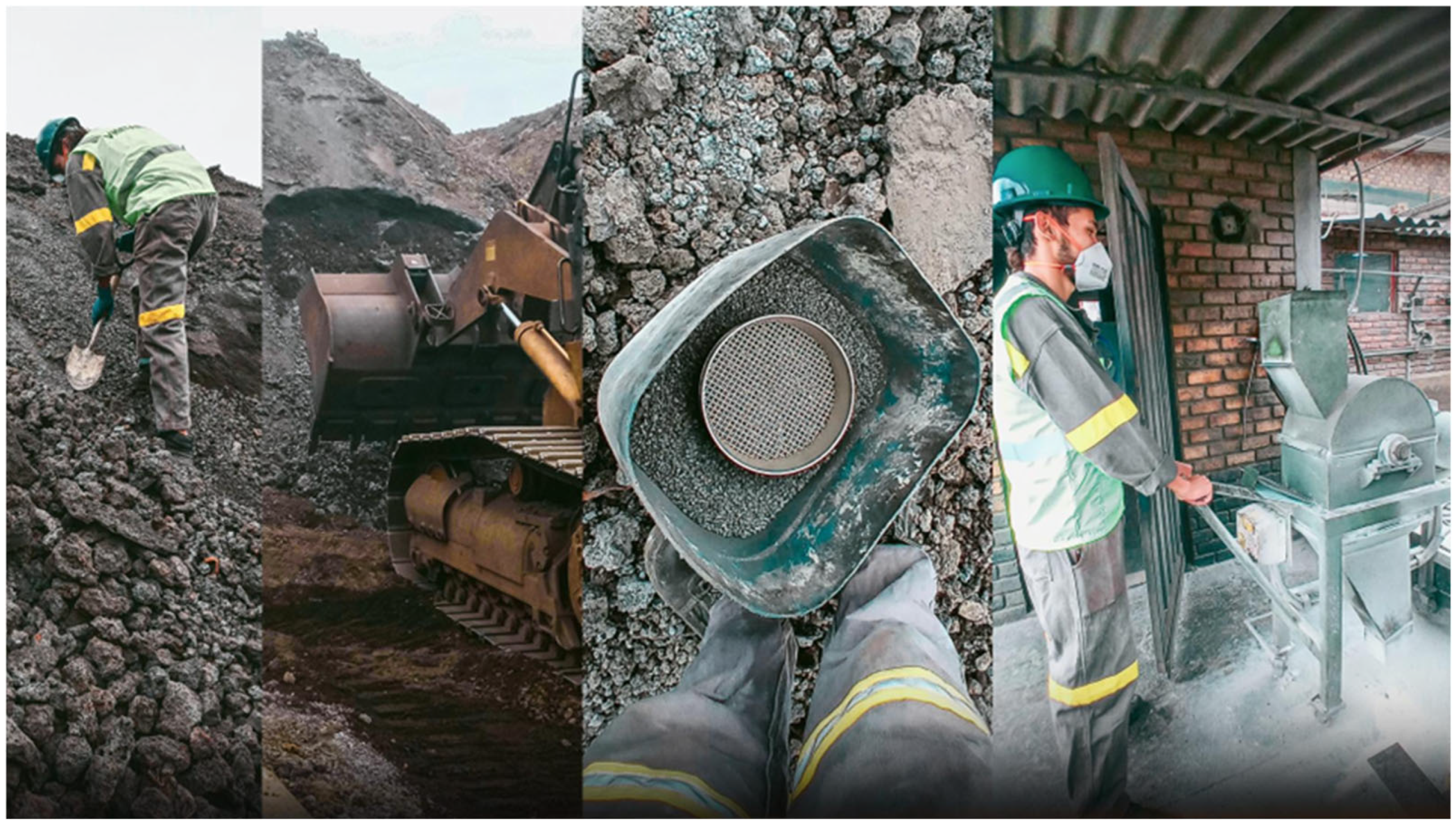
The raw materials used were pharmaceutical-grade potassium dihydrogen phosphate (KH2PO4; KDP) (ABC LABORATORIOS, Bogotá, Colombia) and electric arc furnace (EAF) steel slag from the Reyna steel group, SIDENAL, Sogamoso, Boyacá, Colombia. These raw materials were selected to form an acid–base reaction ceramic paste, where KH2PO4 acts as the acid component (providing phosphate anions) and the EAF slag as the basic component (providing metallic cations). As shown in Figure 1, this interaction allows for the formation of chemically bonded phosphate ceramics (CBPC), from the reaction between the metallic oxides present in the slag (MgO, CaO, ZnO, Al2O3, Fe2O3) and phosphoric acid.

2.2. Slag Sampling and Powder Preparation

A sampling of black EAF slag was carried out in accordance with ASTM D75/D75M-14; Standard Practice for Sampling Aggregates. ASTM International: West Conshohocken, PA, USA, 2019, [16] from the Reyna SIDENAL steel group. As seen in Figure 1, the sampling was performed from a pile of material stored for more than six months to ensure the lowest percentage of moisture and the lowest expansion capacity. A primary grinding was performed to reduce the particle size; 100 kg of slag was subjected to 10 grinding cycles in a hammer mill as shown in Figure 1. Subsequently, sieving was performed using a digital electric sieving machine manufactured by Pinzuar (Bogotá, Colombia), in accordance with NTC 32 (2002) [17], with an eccentric vertical movement and 10-min cycles, equipped with sieves No. 7, 30, 100, 140, and 170, normalized according to ASTM E11-24; Standard Specification for Woven Wire Test Sieve Cloth and Test Sieves. ASTM International: West Conshohocken, PA, USA, 2024 [18].
To obtain a finer granulometry, the slag was subjected to a secondary grinding in the sample preparation laboratory of UPTC Sogamoso, using a Holmes brand disc pulverizer, model LC-350 Preiser Scientific, St. Albans, WV, USA, with a capacity of 400 g per minute. The resulting material was sieved again using a W.S. Tyler Ro-Tap electric sieve shaker (W.S. Tyler, Mentor, OH, USA), in accordance with ASTM C136; Standard Test Method for Sieve Analysis of Fine and Coarse Aggregates. ASTM International: West Conshohocken, PA, USA, 2019 [19], with a speed of 150 pulses/min and a frequency of 278 osc/min with 10-min cycles, equipped with a No. 200 sieve, normalized according to ASTM E-11.
Sampling was performed in accordance with ASTM D75/D75M-14 from different zones of the slag pile to obtain a representative bulk sample of approximately 100 kg. This procedure ensured that the collected material reflected the overall heterogeneity of the slag deposit.
The collected slag was subjected to a multi-stage comminution process. First, primary crushing was carried out using a hammer mill to reduce the initial particle size. Subsequently, secondary grinding was performed with a Holmes disc pulverizer (Model LC-350, 110 V, Preiser Scientific, St. Albans, WV, USA to achieve a finer and more homogeneous powder.
After grinding, the material was sieved in accordance with ASTM E11 to classify the particle size fractions. The final powder fraction was obtained using a No. 200 sieve (75 µm), and the fraction smaller than 75 µm was selected for paste preparation unless otherwise specified.
The particle size distribution (PSD) was determined by sieve analysis and laser diffraction when available; otherwise, sieve-based PSD results were reported. The specific surface area was determined using the BET method when measurements were performed.

2.3. X-Ray Diffraction (XRD)

X-ray diffraction (XRD) analyses were carried out using an XRD 600 X-ray diffractometer (Shimadzu, Kyoto, Japan) equipped with a DECTRIS MYTHEN 1D detector (DECTRIS, Baden-Daettwil, Switzerland).The instrument was operated at 40 kV and 15 mA using Cu Kα radiation (λ = 1.540598 Å), filtered with Ni and a graphite monochromator. These conditions were selected to ensure adequate resolution and signal intensity for crystalline phase identification.
The scanning parameters included a 2θ range from 5° to 90°, with a step size of 0.02° and a counting time of 1 s per step. Data were collected in continuous scan mode to obtain representative diffraction patterns of the analyzed samples.
Phase identification was performed using the ICDD PDF-4 database, allowing the comparison of experimental diffraction peaks with standard reference patterns for accurate mineralogical characterization.

2.4. Preparation of Potassium Dihydrogen Phosphate (KDP)

Potassium dihydrogen phosphate (KDP) was ground using a disc mill and subsequently sieved in accordance with ASTM E11 to obtain controlled particle size fractions. This procedure ensured uniformity and reproducibility in the preparation of the reactive phosphate component.
Two particle size fractions were selected as experimental variables: 75 µm and 150 µm. These fractions were used to evaluate the influence of KDP particle size on the behavior and properties of the formulated pastes.

2.5. Preparation of Phosphate Ceramic Paste

The paste was prepared by mixing EAF slag powder and KH2PO4 in predetermined weight ratios in order to evaluate the effect of phosphate content on the reaction process and final properties. The proportions used were 1:7 (12.5 wt.% KDP), 1:4 (20 wt.% KDP), and 1:2 (33.33 wt.% KDP).
Different liquid-to-solid (L/S) ratios were also assessed to analyze their influence on workability and setting behavior. The evaluated L/S ratios were 1:15 (6.25 wt.% water) and 1:20 (4.76 wt.% water).
The mixing procedure consisted of an initial dry blending of the powders for 2 min to ensure uniform distribution of the components. Water was then added, followed by mechanical or manual mixing for 5–15 min until a homogeneous paste was obtained.
No thermal curing was applied. The samples were cured under ambient conditions at 23 ± 2 °C and a relative humidity of 50–60%. The curing times evaluated were 7, 15, 28, and 49 days to monitor the evolution of the material properties over time.

2.6. Specimen Fabrication by Pressing

Cylindrical specimens were fabricated by uniaxial pressing in order to obtain compact samples suitable for mechanical and microstructural evaluation. The specimens had a nominal diameter of 16 mm and a height of 32 ± 2 mm, ensuring a consistent geometry for comparative analysis.
Two different compaction pressures were applied, namely 1 MPa and 3 MPa, with a pressing time of 60 s for each specimen. These parameters were selected to evaluate the influence of forming pressure on densification and subsequent properties.
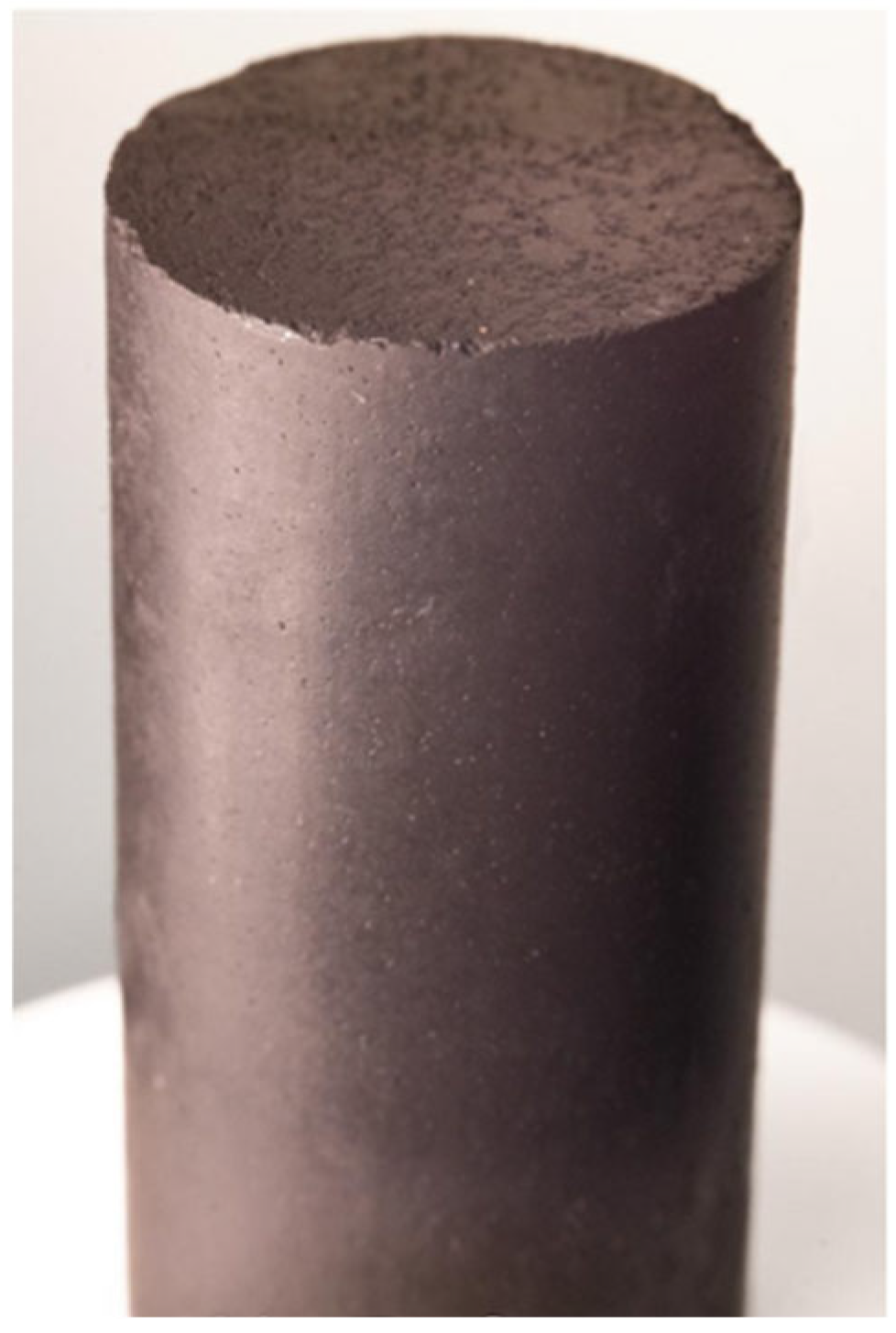
The green density (ρg) was calculated from the measured mass and the corresponding geometric volume immediately after pressing. The mold assembly used for specimen fabrication is shown in Figure 2.

2.7. Compressive Strength Testing

Compressive strength tests were conducted in accordance with ASTM C39/C39M-21; Standard Test Method for Compressive Strength of Cylindrical Concrete Specimens. ASTM International: West Conshohocken, PA, USA, 2021 [20], to evaluate the mechanical performance of the prepared specimens. The experiments were carried out using a WDW100 UTM universal testing machine (Jinan Hensgrand Instrument Co., Ltd., Shenzhen, China).
The tests were performed under uniaxial compression at a crosshead speed of 1 mm/min. For each experimental condition, a minimum of three specimens was tested to ensure the reliability and reproducibility of the results.

3. Results and Discussion

3.1. Material Shaping Method

As a result of the comparative analysis between the casting and pressing methods, it was identified that pressing is the most suitable for the elaboration of monolithic objects from the chemical-reaction ceramic mixture. By achieving pieces with greater density, cohesion, and mechanical strength, it optimizes both the structural behavior and the efficiency of the process. Unlike the casting method, which requires fluid mixtures and, therefore, a greater proportion of water (between 60% and 66%), the paste, when shaped by pressing, achieved strengths greater than 50 MPa using a much lower proportion (4.76%). This difference is fundamental, since in acid–base systems such as the one developed in this research, an excess of water stimulates unwanted hydration reactions in the calcium silicates present in the slag, generating CSH gel. This gel provides strength in Portland cements, but in this phosphate system, it forms weak structures that reduce compressive strength (Penn State University, s.f.). In addition, the excess water facilitates the formation of steam bubbles during the dissolution of CaO and the release of heat [10], which remain trapped as the mixture sets, causing internal porosity that negatively affects the structural integrity of the material [11]. The pressing method eliminates this dependence on fluidity, since the filling and adaptation of the mixture to the mold is achieved by applying external pressure, not by its viscosity. This allows for a significant reduction in the amount of water and an improvement in the quality of the material. Additionally, by applying pressure (3 MPa), the system is compacted, decreasing porosity and generating an increase in the effective contact area between particles. According to simple cubic packing models [16], this increase in contact is directly related to greater strength, since the load is distributed over a wider surface, meaning that with greater pressure, there is a greater real contact area (Ar). Furthermore, it is hypothesized that during pressing, as the particles are closer to each other, the formation of a greater amount of iron and calcium phosphates is favored, compounds responsible for the structure and bonding between particles, as evidenced by [15] in the chemical and morphological analysis of cements formed from steel slags. In a group, compression shaping proved to be the most suitable method for the production of monolithic objects, by improving mechanical strength, reducing porosity, and allowing for greater use of the recycled material (slag), consolidating its practical application in real manufacturing contexts.

3.2. Compressive Strength over Time of Specimen

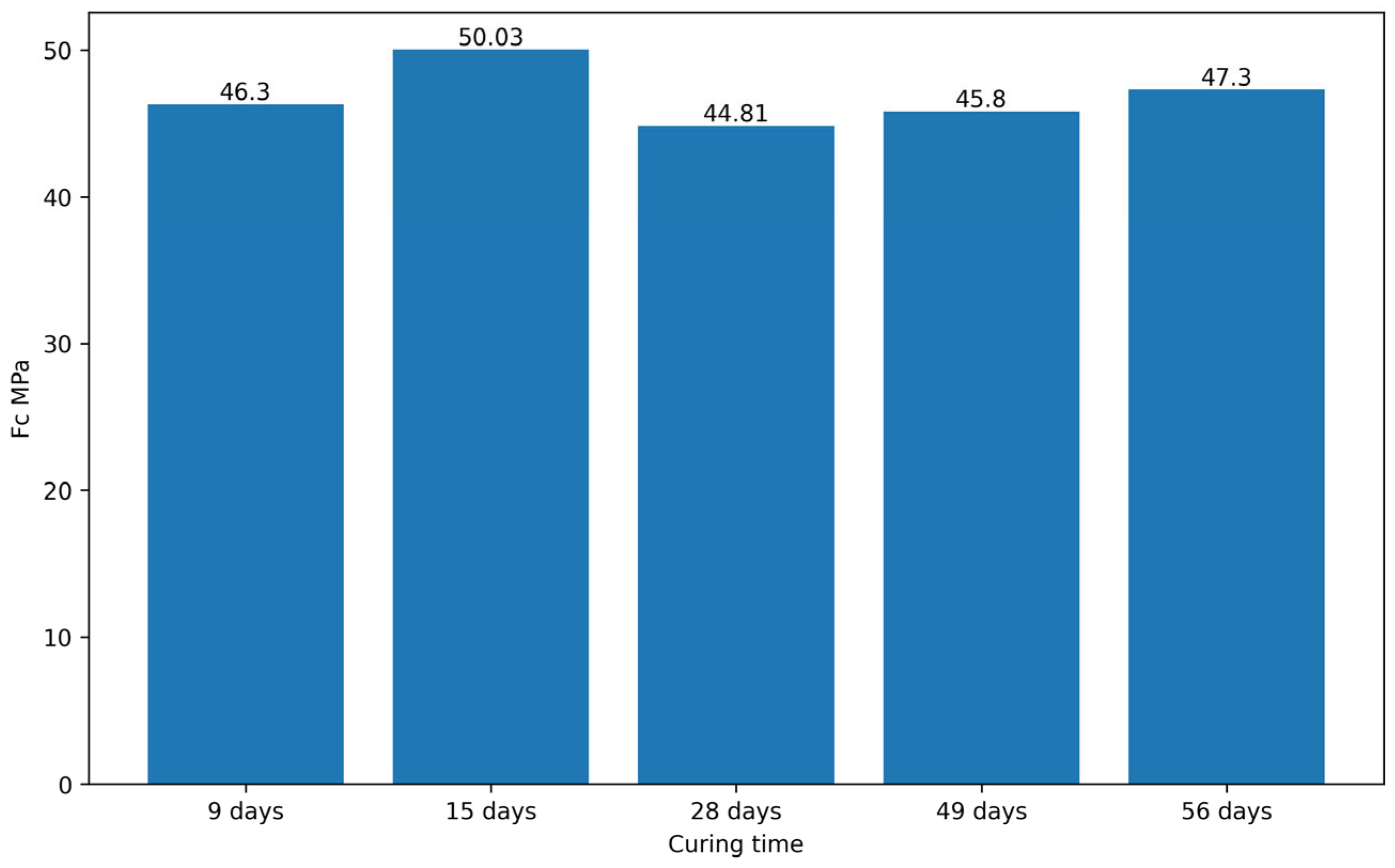
The slight decrease in strength observed between days 15 and 28, followed by an increase evident from day 49, is consistent with the non-linear behavior presented in similar studies on phosphate cements. In the research carried out by Hou et al. [21], they showed that by adding calcined coal gangue to a magnesium phosphate cement, the strength reaches an early peak, drops slightly after the first 24 h, then recovers and exceeds its initial values thanks to microstructural filling and late hydration reactions of the gangue. Similarly, in the research by Li et al. [2], it was found that in MPC (Magnesium Phosphate Cements) retarded with glacial acetic acid, there was a rapid increase in strength, a small intermediate drop, and a subsequent recovery by day 28, attributable to the crystallization and rearrangement of the struvite and acetate products in the cementitious matrix. And, in aluminum-rich cements designed for geothermal wells, Pyatina and Sugama [22] recorded an initial loss of strength during the first week, followed by a gradual rebound as hydrothermal curing was prolonged, due to phase transformations that stabilize the structure in the long term. Figure 3 presents the evolution of compressive strength as a function of curing time for specimens prepared under different processing conditions.
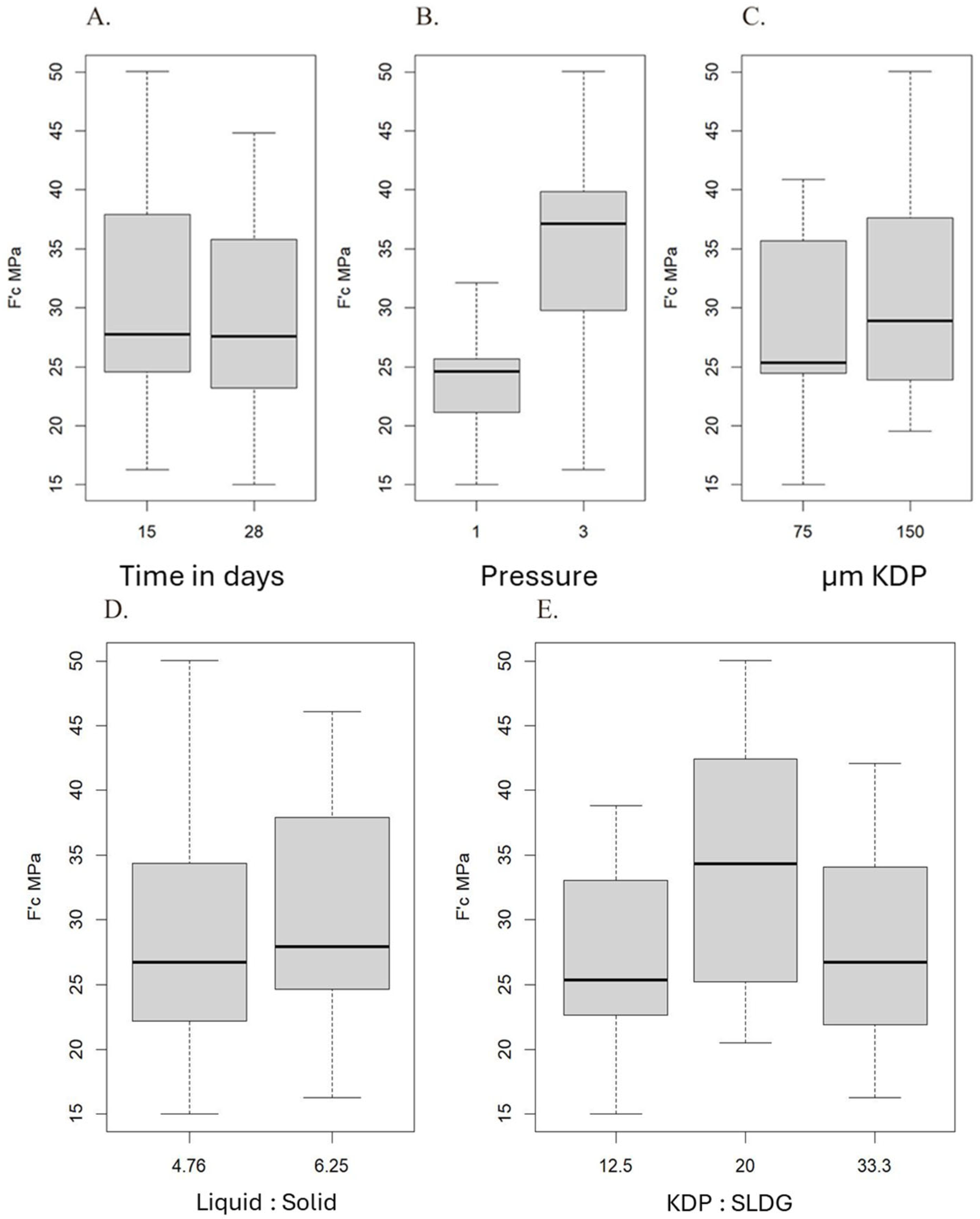
Due to the presence of crystalline phases of calcium phosphate (CaHPO4·2H2O, Ca(H2PO4)2·H2O) in phosphate cements made with EAF slags [15], what is typically expected is an initial decrease in strength before its subsequent stabilization [17]. This same trend was also reported by Cárdenas Balaguera and Gómez Botero [15], who observed a loss of up to 85% of the strength in phosphate cements made with steel slag after immersion in Na2SO4, followed by a partial recovery towards day 21, showing a similar oscillating behavior. Taken together, this evidence confirms that the pattern of early gain, slight intermediate decrease, and progressive recovery is a characteristic of the complex microstructuring of phosphate cements. On the other hand, in Figure 4, item B, the influence of pressure on the response variable can be observed, with a mean compressive strength of 24.2 MPa when the shaping pressure is 1 MPa and a mean of 35.5 MPa when the pressure is 3 MPa, showing that greater compaction pressure leads to greater strength. In Figure 4, item C, the influence of KDP granulometry on the response variable is observed. The compressive strength presents a mean of 28.2 MPa when the granulometry is 75 µm and a mean of 31.4 MPa for 150 µm, showing that with a larger particle size, there is greater strength. The analysis of the main effects, illustrated in Figure 4, reveals important trends in compressive strength (MPa). Item A shows that curing time has a non-significant influence, with a slight decrease in strength as it increases from 15 to 28 days. On the other hand, item B shows that compaction pressure has a notable impact, where a greater pressure of 3 MPa is associated with a greater compressive strength, this being the variable with the most pronounced effect. Finally, item C indicates that KDP granulometry also influences strength, favoring a particle size of 150 µm. The analysis of the main effects, illustrated in Figure 4, items D and E, shows that for the liquid/solid ratio, the 1:15 (6.25%) proportion is the proportion with the highest mean compressive strength (Q2). On the other hand, for the KDP/SLDG ratio, the 1:4 (20%) proportion demonstrates that it reached the highest mean compressive strength (Q2), with a mean centered between Q1 and Q3, even slightly closer to Q3, which suggests a balanced variable with a low tendency to high values. In fact, the highest strength observed in this category also corresponds to this proportion, which supports the hypothesis that a lower relative amount of KDP (keeping other variables constant) favors the development of a denser and structurally efficient matrix. In Figure 4, E we can see the non-linear behavior of KDP hydrophosphate with its respective concentrations of 12.5%, 20%, and 33.33%, KDP:SLDG ratios, 1:7, 1:4, and 1:2 respectively, and its influence on compressive strength (F’c MPa). At a concentration level of 12.5% KDP with respect to (SLDG), the compressive strength presents the lowest value among the three levels evaluated, with an approximate mean of 27.4 MPa. When the proportion is increased to 20%, a considerable increase in strength is observed, reaching the highest mean value of the experiment (34.39 MPa), which suggests that this is the optimal level within the analyzed range. However, when the concentration is increased even further to 33.33%, the strength decreases again, with a mean close to 27.79 MPa, which, although slightly higher than the 12.5% value, is still lower than the value reached with 20%.
The compressive strength values at 28 days showed a slight decrease compared to those measured at 7 days. This behavior may be associated with internal shrinkage phenomena and moisture redistribution occurring during prolonged curing at ambient conditions. As water progressively evaporates from the matrix, localized microstructural stresses may develop, potentially leading to microcrack formation and partial loss of mechanical integrity. Additionally, changes in internal porosity during extended curing could contribute to the observed reduction in compressive strength. Further microstructural analysis would be required to confirm these mechanisms.

3.3. Fracture Analysis

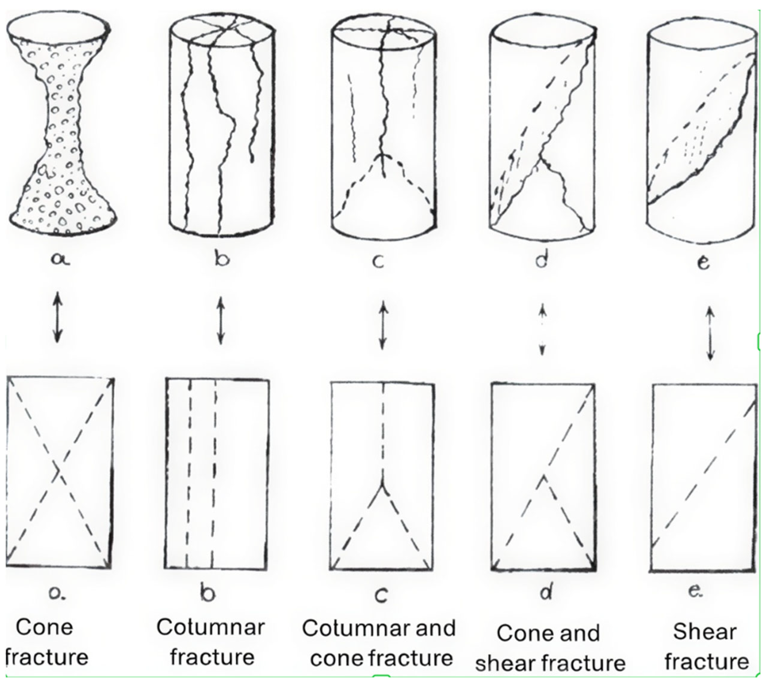
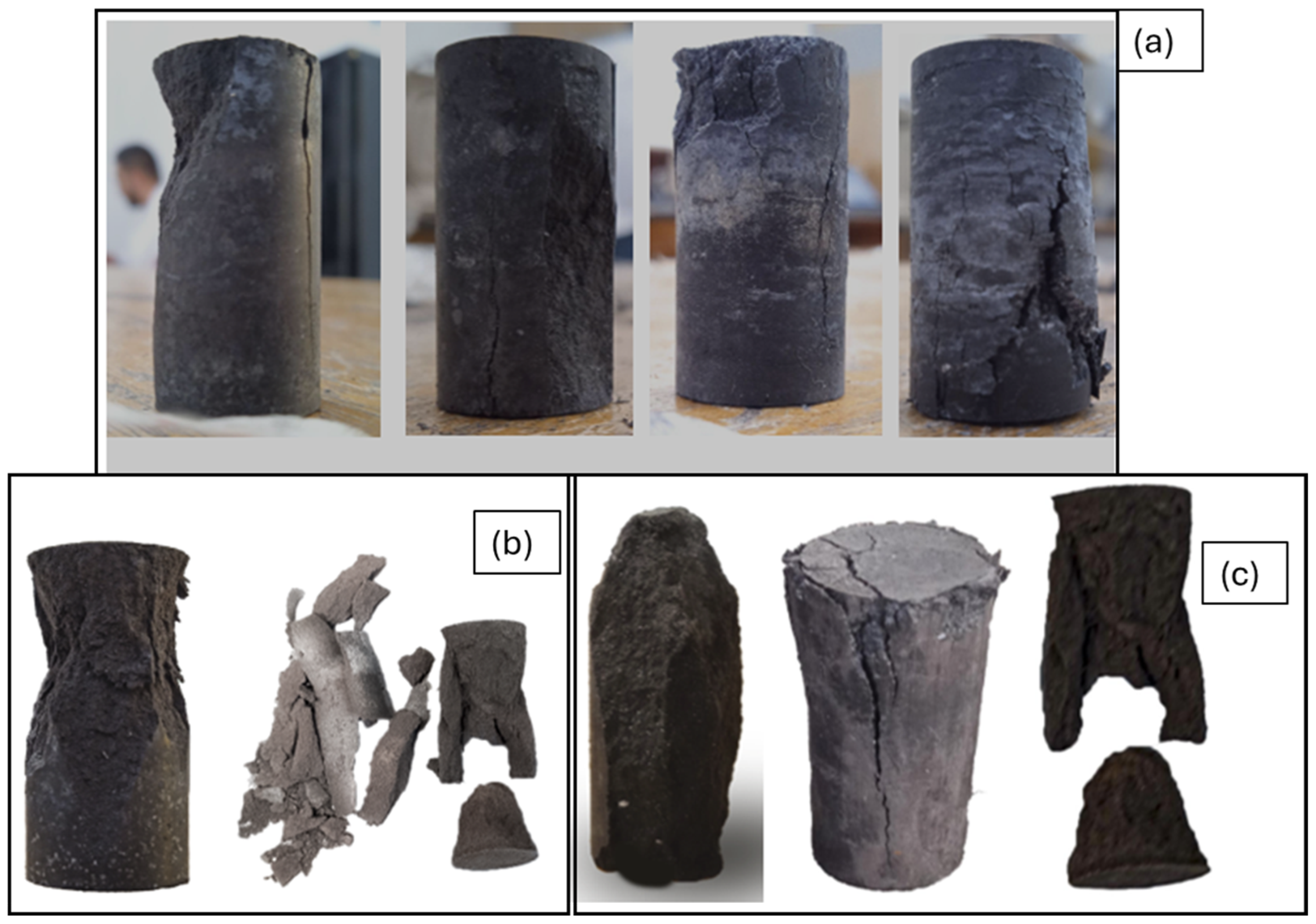
According to ASTM C 39 standards, the fractures observed in Figure 5—obtained after the compressive strength tests—allowed for a visual analysis of the behavior of the concrete specimens.
The compressive strength tests began with a batch of specimens from previous tests whose faces had not been prepared with the parallel finish required by ASTM C39. In Figure 6, it was observed that these specimens presented longitudinal or column-type fractures, which indicates an eccentric or non-uniform load. This failure pattern was interpreted as a direct consequence of the face preparation, since the applied load was not distributed properly along the central axis of the specimen. Given these results, it was decided to rectify the faces of the specimens from the experimental design group to ensure their parallelism. In this second set of tests, most of the specimens presented the cone failure pattern, and in some cases, cone and column, this is the expected behavior, since not always a single type of failure occurs. In some specimens, it is possible for several types of failures to occur at the same time. This result validated that the obtained compressive strength is the true capacity of the concrete, since the load was applied uniformly and without shape defects. The process of rectifying the faces of the specimens not only allowed for compliance with the standards of ASTM C39, but also demonstrated the importance of adequate sample preparation to obtain reliable and representative results of the material’s strength.

3.4. Liquid/Solid Ratio and Its Influence on the Paste

The relationship between liquid and solid in the paste directly influences mechanical strength. In the experimental design, two proportions were evaluated: 1:15 (6.25%) and 1:20 (4.76%), observing notable differences in compressive strength. Although the statistical analysis showed that, on average, the 1:15 ratio (31.55 MPa) produced a slightly higher strength than the 1:20 ratio (28.82 MPa), the maximum strength observed in the experiment was reached with a 1:20 mixture, under specific conditions: 3 MPa pressure, 150 µm KDP granulometry, and a KDP/SLDG ratio of 1:4. In this case, a strength of up to 50 MPa was obtained, indicating that a lower liquid content can enhance the densification and structural development of the material when combined with optimal parameters. It has been observed that mixtures with a lower liquid content tend to form more compact and less porous matrices, which improves mechanical strength. However, excessively low water levels can affect workability and cause failures due to poor compaction. As mentioned by Cárdenas Balaguera and Gómez Botero [15], “the prepared specimens showed rapid setting with strong exothermic reactions […]. Both phenomena could be associated with the amount of water present in the reaction,” highlighting that the proportion of liquid in the mixture directly affects the material’s behavior. Furthermore, the same study reports that lower liquid/solid ratios (such as 1.5:1 or 3:2) generated denser and stronger cements, while higher proportions (such as 2:1) resulted in less compact structures.

3.5. X-Ray Diffraction (XRD) Analysis

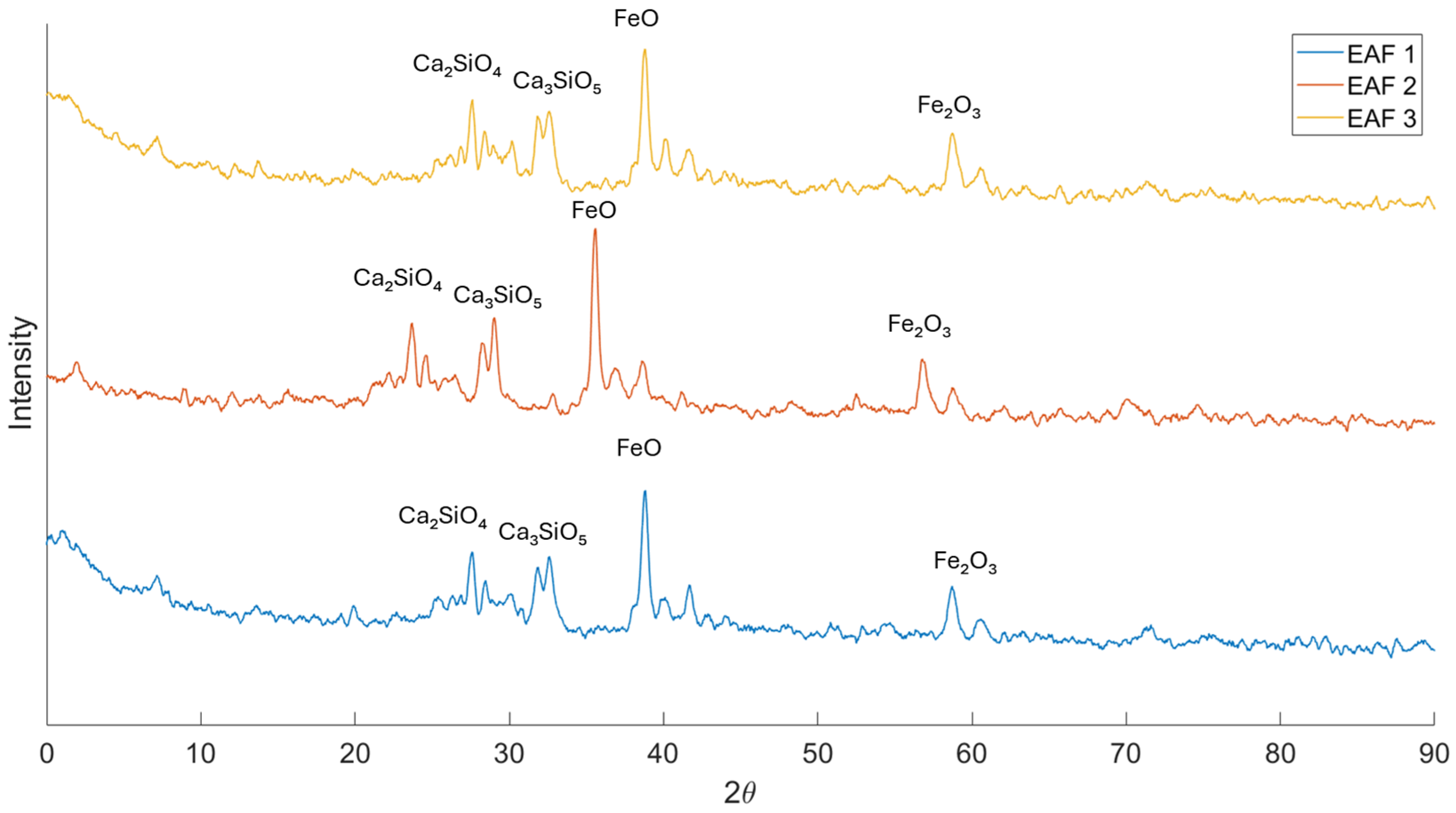
Figure 7 shows the X-ray diffraction (XRD) patterns corresponding to three electric arc furnace slag samples (EAF), recorded over a 2θ angular range from 0° to 90°. In all cases, a characteristic pattern of multiphase materials is observed, with the coexistence of well-defined diffraction peaks superimposed on a continuous background. This behavior indicates the simultaneous presence of crystalline phases and a partially amorphous fraction, which is typical of metallurgical slags.
The three diffractograms exhibit high-intensity peaks mainly concentrated between 30° and 45° (2θ), along with additional reflections at higher angles, particularly around 57–62°. This is consistent with the presence of calcium silicates and iron oxides, which are phases commonly reported in EAF slags. The intensity and position of these peaks are in good agreement with phases such as Ca2SiO4, Ca3SiO5, FeO, and Fe2O3, which have been widely described in the literature for this type of industrial residue.
Slight variations in the diffraction peak positions attributed to FeO were observed among the different samples. These minor shifts may be associated with lattice distortions, residual stresses induced during compaction, or partial ionic substitution within the crystal structure. Additionally, peak overlapping with neighboring phases cannot be ruled out. Since no Rietveld refinement was performed, these variations are interpreted cautiously and do not necessarily indicate the formation of new iron-based phases.
The overall similarity among the three patterns indicates that EAF 1, EAF 2, and EAF 3 samples possess a comparable mineralogical composition, which is consistent with their common industrial origin and similar cooling and solidification processes. Nevertheless, slight variations in the relative intensity of some peaks are observed, which may be attributed to differences in the proportion of crystalline phases, the degree of crystallinity, or minor heterogeneities inherent to the metallurgical slag formation process.
From a functional standpoint, the presence of these crystalline phases is particularly relevant for the development of the chemically bonded phosphate ceramics studied in this work. Calcium and iron silicates and oxides act as sources of divalent and trivalent cations (Ca2+, Fe2+/Fe3+) during the acid–base reaction with potassium dihydrogen phosphate (KDP). The interaction between the basic oxides present in the slag and KH2PO4 is expected to promote the formation of phosphate-based binding phases, as reported in similar chemically bonded phosphate systems [9,15]. However, the current XRD analysis does not provide direct evidence of well-crystallized calcium or iron phosphate phases in the reacted specimens. Further phase characterization is required to confirm the reaction products.
Overall, the XRD analysis confirms the multiphase and reactive nature of the EAF slag, supporting its suitability as a raw material for the fabrication of chemically bonded phosphate ceramics. Furthermore, from a mineralogical perspective, these results help explain the good mechanical performance observed in the samples consolidated by the pressing method.

4. Conclusions

This study assessed the feasibility of producing phosphate-based ceramic materials using electric arc furnace (EAF) slag and potassium dihydrogen phosphate (KH2PO4) through a uniaxial pressing route followed by ambient curing.
The experimental results indicate that compaction pressure plays a decisive role in mechanical performance. Specimens consolidated at 3 MPa consistently exhibited higher compressive strength values compared to those pressed at 1 MPa, confirming that improved particle rearrangement and densification contribute to enhanced mechanical behavior.
The particle size of KH2PO4 also influenced compressive strength. Under similar processing conditions, mixtures prepared with 150 µm KDP particles showed superior mechanical performance compared to those prepared with 75 µm particles. Bulk density measurements suggest that these differences are associated with packing efficiency and consolidation behavior rather than solely chemical effects.
The liquid-to-solid (L/S) ratio and the KDP-to-slag (KDP/SLDG) ratio were found to significantly affect strength development. Optimized combinations of these parameters resulted in improved compressive strength, indicating that both matrix formation and compaction contribute to final performance.
Compressive strength evolution over curing time demonstrated a non-linear trend, characteristic of phosphate-based systems. Strength development after one week of curing confirms that ambient temperature processing is sufficient to achieve structurally stable monolithic specimens within the evaluated conditions.
Within the experimental scope of this study, EAF slag proved to be a viable precursor for the production of phosphate ceramic materials using a low-pressure forming process. The results highlight the importance of processing parameter optimization to maximize mechanical performance.

Author Contributions

Investigation, P.A.R.C., L.P.E.L. and C.A.C.B.; Writing—original draft, P.A.R.C., L.P.E.L., A.F.R.-N. and C.A.C.B.; Writing—review & editing, A.F.R.-N., P.A.R.C., L.P.E.L. and C.A.C.B., contributed to all phases of the research from conception to experimental development, analysis of results, and writing of the article. All authors have read and agreed to the published version of the manuscript.

Funding

This research was supported by the Vice-Rectory for Research and Extension (VIE), Universidad Pedagógica y Tecnológica de Colombia, under Call No. 08 of 2026. Códice SGI 3712 in the UPTC.

Institutional Review Board Statement

Not applicable.

Informed Consent Statement

Not applicable.

Data Availability Statement

The data presented in this study are available on request from the corresponding author.

Acknowledgments

The authors would like to express their gratitude to Technological Development Research Institute-CIMADI from the Technological and Pedagogical University of Colombia (UPTC).

Conflicts of Interest

The authors declare no conflicts of interest.

References

  1. Hernandez, N.M.; Sánchez, J.A.V.; Manzano, M.A.R.; García, H.M.B.; Prado, D. Uso de la escoria de horno de arco eléctrico (ehae) como agregado fino para la producción de mortero estructural. In Proceedings of the Encuentro Internacional de Educación en Ingeniería, Virtual, 18–21 August 2020; EIEI ACOFI: Bogotá, Colombia, 2020; pp. 1–10. [Google Scholar] [CrossRef]
  2. Jun, L.; Yong-Sheng, J.; Guodong, H.; Cheng, J. Retardation and reaction mechanisms of magnesium phosphate cement mixed with glacial acetic acid. RSC Adv. 2017, 7, 46852–46857. [Google Scholar] [CrossRef]
  3. Jiang, Y.; Ling, T.C.; Shi, C.; Pan, S.Y. Characteristics of steel slags and their use in cement and concrete—A review. Resour. Conserv. Recycl. 2018, 136, 187–197. [Google Scholar] [CrossRef]
  4. Dvorkin, L.; Dvorkin, O.; Ribakov, Y.; Zhitkovsky, V. Using granite siftings for producing vibro-pressed fine-grained concrete. KSCE J. Civ. Eng. 2017, 21, 2252–2258. [Google Scholar] [CrossRef]
  5. Iacobescu, R.I.; Koumpouri, D.; Pontikes, Y.; Saban, R.; Angelopoulos, G.N. Valorisation of electric arc furnace steel slag as raw material for low energy belite cements. J. Hazard. Mater. 2011, 196, 287–294. [Google Scholar] [CrossRef] [PubMed]
  6. Piatak, N.M.; Parsons, M.B.; Seal, R.R. Characteristics and environmental aspects of slag: A review. Appl. Geochem. 2015, 57, 236–266. [Google Scholar] [CrossRef]
  7. Vieira, C.M.F.; Amaral, L.F.; Monteiro, S.N. Recycling of Steelmaking Plant Wastes in Clay Bricks. In Current Topics in the Utilization of Clay in Industrial and Medical Applications; IntechOpen: London, UK, 2018. [Google Scholar] [CrossRef]
  8. World Steel in Figures 2025—Worldsteel.org. Available online: https://worldsteel.org/data/world-steel-in-figures/world-steel-in-figures-2025/ (accessed on 10 September 2025).
  9. Cárdenas, C.; Mácová, P.; Gómez, M.; Zárybnická, L.; Ševčík, R.; Viani, A. Formation, Properties, and Microstructure of a New Steel Slag–Based Phosphate Cement. J. Mater. Civ. Eng. 2021, 33, 04021330. [Google Scholar] [CrossRef]
  10. An Overview of Lime Slaking and Factors—An Overview of Lime Slaking and Factors That Affect the—Studocu. Available online: https://www.studocu.com/pe/document/universidad-nacional-mayor-de-san-marcos/electrodinamica-clasica/an-overview-of-lime-slaking-and-factors/25905611 (accessed on 10 September 2025).
  11. Wagh, A.S.; Singh, D.; Jeong, S.Y. Method of Waste Stabilization via Chemically Bonded Phosphate Ceramics; Argonne National Laboratory: Lemont, IL, USA, 1998. [Google Scholar]
  12. De Guzmán, D.S. Tecnología del Concreto y del Mortero; Pontificia Universidad Javeriana: Santafé de Bogotá, Colombia, 2001; p. 349. [Google Scholar]
  13. Zhenyu, L.; Yang, H.; Xiaojie, F.; Zhongyuan, L.; Shuzhen, L. Preparation of Porous Materials by Magnesium Phosphate Cement with High Permeability. Adv. Mater. Sci. Eng. 2018, 2018, 5910560. [Google Scholar] [CrossRef]
  14. Meléndez Rodríguez, F.J. Desarrollo de una Barbotina Cerámica para Vaciado de Alta Presión Mediante el uso de la Determinación de la Permeabilidad en el Filtro Baroid; Universidad Autónoma de Nuevo León: Monterry, Mexico, 2002. [Google Scholar]
  15. Cárdenas-Balaguera, C.A.; Gómez-Botero, M.A. Engineering applications of chemically-bonded phosphate ceramics. Ing. Investig. 2019, 39, 10–19. [Google Scholar] [CrossRef]
  16. D75/D75M Standard Practice for Sampling Aggregates. Available online: https://store.astm.org/d0075_d0075m-14.html (accessed on 2 March 2026).
  17. Silva, S.J.H. Aplicación de la Norma NTC 32 Para la Elaboración Del Procedimiento de Calibración en Tamiz Estándar de Ensayo Para un Laboratorio de Metrología. 2020. Available online: https://repositorio.unal.edu.co/handle/unal/78675 (accessed on 2 March 2026).
  18. E11 Standard Specification for Woven Wire Test Sieve Cloth and Test Sieves. Available online: https://store.astm.org/e0011-24.html (accessed on 2 March 2026).
  19. C136/C136M Standard Test Method for Sieve Analysis of Fine and Coarse Aggregates. Available online: https://store.astm.org/c0136_c0136m-14.html (accessed on 2 March 2026).
  20. ASTM C39/C39M-20; Test Method for Compressive Strength of Cylindrical Concrete Specimens. ASTM International: West Conshohocken, PA, USA, 2020. [CrossRef]
  21. Hou, L.; Li, J.H.; Tong, L.X.; Qi, Z. Effect of calcined coal gangue on the mechanical property and microstructure of magnesium phosphate cement. Appl. Mech. Mater. 2012, 174–177, 943–946. [Google Scholar] [CrossRef]
  22. Pyatina, T.; Sugama, T. Aluminum-Rich Cements for High Temperature Geothermal Wells. In Proceedings of the 49th Workshop on Geothermal Reservoir Engineering Stanford University, Stanford, CA, USA, 12–14 February 2024. [Google Scholar]
Figure 1. Harvesting and milling process at SIDENAL.
Ceramics 09 00036 g001
Figure 2. Shaped material.
Ceramics 09 00036 g002
Figure 3. Compressive strength over time of the specimen.
Ceramics 09 00036 g003
Figure 4. Effect of Liquid/Solid and KDP/SLDG Ratios on Compressive Strength: (A) Compressive strength vs. curing time (days); (B) Compressive strength vs. compaction pressure; (C) Compressive strength vs. KDP particle size; (D) Compressive strength vs. liquid/solid ratio; (E) Compressive strength vs. KDP/SLDG ratio.
Ceramics 09 00036 g004
Figure 5. Fracture typology, according to ASTM C39.
Ceramics 09 00036 g005
Figure 6. Fractures observed in compression tests: (a) Progressive axial crack development with longitudinal splitting and localized surface damage; (b) Catastrophic brittle disintegration following compressive overload y; (c) Axial splitting failure accompanied by structural collapse and fragment detachment.
Ceramics 09 00036 g006
Figure 7. X-ray diffraction (XRD) patterns corresponding to three electric arc furnace slag samples (EAF 1, EAF 2, and EAF 3).
Ceramics 09 00036 g007
Disclaimer/Publisher’s Note: The statements, opinions and data contained in all publications are solely those of the individual author(s) and contributor(s) and not of MDPI and/or the editor(s). MDPI and/or the editor(s) disclaim responsibility for any injury to people or property resulting from any ideas, methods, instructions or products referred to in the content.