Article

Control of the SiC Polytypes in SiC Bonded Diamond Materials

Fraunhofer IKTS—Fraunhofer Institute for Ceramic Technologies and Systems, 01277 Dresden, Germany
*
Author to whom correspondence should be addressed.
Ceramics 2025, 8(3), 90; https://doi.org/10.3390/ceramics8030090
Submission received: 21 May 2025 / Revised: 1 July 2025 / Accepted: 15 July 2025 / Published: 18 July 2025
(This article belongs to the Special Issue Advances in Ceramics, 3rd Edition)

Abstract

Silicon carbide-bonded diamond materials produced by pressureless reaction infiltration of diamond preforms have high wear resistance and thermal conductivity, making them ideal for a range of industrial applications. During infiltration, the Si is typically converted to cubic β-SiC. The aim of the work was to investigate the extent to which the formation of hexagonal α-SiC can be achieved by adding α-SiC or AlN nuclei to the preform. Detailed microstructural investigations using XRD, high-resolution FE-SEM, and EBSD analyses show that both AlN and SiC serve as nuclei for α-SiC. Regardless of this, a large proportion of β-SiC forms on the surface of the diamonds. However, the added nuclei change the structure of the SiC framework that forms.

1. Introduction

In superhard SiC-bonded diamond materials, which can be produced by the pressureless reactive silicon infiltration of diamond preforms, cubic β-SiC forms around the diamond grains [1,2,3,4,5,6,7,8,9]. Typical sintered SiC materials or Si-infiltrated materials essentially exhibit the hexagonal SiC polytypes [10,11,12,13,14].
It is known that the different polytypes exhibit different electrical properties because β-SiC has a lower band gap than the hexagonal polytypes (Table 1) [11,12,13,14,15]. Little is known about differences in wear properties and hardness. The microhardness values are similar; however, the scatter of the values is larger than the differences between the polytypes [16,17]. This could also be caused by the anisotropy of the hardness values of the different crystallographic planes or the different doping [18,19]. The 3C-SiC exhibits a slightly lower Young’s modulus in comparison to 2H-SiC and the 6H-polytypes [16].
Nevertheless, the hexagonal polytypes are thought to be slightly harder and, based on this, more wear-resistant. Luo et al. [17] investigated the machinability of SiC polytypes. They state a slightly higher resistance of 3C-SiC against cutting in comparison to 6H- and 4H-SiC. The only difference in the crystal structure of the polytypes is the different stacking sequences of individual layers, which are arranged perpendicular to the c-axis of the hexagonal unit cell or the space diagonal of the cubic unit cell (3 layers). The Ramsdell notification is used to distinguish the polytypes from one another (Table 1). The different polytypes can also be considered as ordered stacking faults. At low synthesis temperatures, the primary phase is cubic 3C-SiC. The dominant method of SiC synthesis—the Acheson process—generates dominantly hexagonal polytypes (mostly 6H-SiC) due to the high process temperatures [10,13].
The phase stability study by S. Sugiyama [20] shows that 3C-SiC should be the thermodynamically stable modification up to approximately 1600 °C at ambient pressure. This indicates the stability of the polytypes at high temperatures. However, the differences in the thermodynamic functions are extremely small, so that this question has not been conclusively resolved. Even small amounts of impurities can lead to the formation of different polytypes, which can be caused by both kinetic and thermodynamic effects. For example, it is known that >0.2 wt.% metallic Al stabilizes the 4H-SiC polytype [10]. AlN addition leads to the formation of 2H-SiC because it forms a continuous solid solution at least at high temperatures, since both compounds have the wurtzite structure. [10] The addition of small amounts of Al, B, and N also changes the electrical properties of the SiC semiconductor [10,21]. G. Oleinik [15] points out the accelerating effect of defects (especially Al and N) during the transformation of polytypes.
Since the hexagonal polytypes may have a higher wear resistance, the question is whether the hexagonal polytypes can also be formed in the temperature range 1400–1600 °C during silicon infiltration. Kuang et al. [22] were able to synthesize α-SiC powder at 1200 °C by microwave heating of silicon and graphite using AlN as a seed. In this case, essentially 4H-SiC was produced when 5–10 wt.% AlN was added, and 2H-SiC was produced at higher levels. AlN serves as a seed because it has a similar structure.
During the carbothermic synthesis of SiC from carbon and SiO2 in the microwave, an increased α-SiC content could be achieved by adding α-SiC particles. [23].
The analysis of SiC-BN composite materials showed that BN has no direct influence on the stability of the SiC polytypes. However, when the BN decomposes in the manufacturing process and generates a nitrogen atmosphere, the 3C-SiC polytype is stabilized [24].
It is well known that B has a strong influence on the sintering of SiC and grain growth during solid phase sintering at high temperatures. Boron in silicon melts reduces grain growth by Ostwald ripening. This has been used to prevent fiber degradation in C/C-SiC or SiC/SiC composites. In the case of C/C-SiC composites, an amorphous B4C phase was detected at the C/SiC interface, which is likely to be a cause of the altered kinetics. In addition to the 3C-SiC growth, the growth of 6H-SiC needles from the B-containing Si melt was also observed [25]. Therefore, it can be assumed that B also influences the formation of SiC crystals in the case of reaction bonding of diamond. The influence of boron on the microstructure and electrical conductivity of SiC bonded diamond composites is described elsewhere [26].
The investigation of the microstructural evolution of Si-infiltrated silicon carbide reveals that the forming secondary SiC grows mainly on the existing SiC crystals. In this process, the polytype of the nucleus remains. Primary (existing in the preform) and secondary SiC (reactively formed during infiltration) could be easily distinguished using IN-LENS detectors [27]. Similar behavior is to be expected in the case of SiC-bonded diamond materials, since the infiltration processes are very similar.
Zhang et al. investigated a material produced by a reactive Si infiltration of SiC and diamond. However, they did not investigate the polytype formation in detail [28]. An opposite procedure was carried out in [29]. Small amounts of diamond were added to the SiC mixture as a carbon source in order to achieve a low residual silicon content in the silicon-infiltrated materials. The influence on polytypes formation was not investigated.
The addition of Al to the silicon melt did not result in an intensive formation of α-SiC crystals in previous investigations. In particular, Al4C3 was formed at the interfaces with the diamond, since an Al-rich eutectic melt phase forms at the beginning of infiltration, even at low Al contents in the alloy. This leads to the formation of Al4C3 [30]. Al4C3 is chemically unstable and therefore weakens the material. The aim of this work was therefore to try to control the polytype formation using two different approaches, adding α-SiC and AlN particles as seeds.

2. Materials and Methods

Diamond powders with overage grain sizes of 50 and 10 µm from VMB VDiamant (Vollstädt Diamant GmbH, Seddiner See, Germany) were used for the research. The diamond fractions were mixed in the ratio 70/30 by weight. Additionally, different SiC powder (Table 2) and AlN (grade H, Tokuyama, Japan) were admixed to the diamond using a turbula mixer. The mixed composition was transferred to an alcoholic solution of phenolic resin and dried in the rotavap. The resin content in the dried sample was 5 wt%. The resulting granules were crushed in the disk mill (Pulverisette 13, FRITSCH GmbH, Idar Oberstein, Germany). The samples were uniaxially pressed into pills with a diameter of 30 mm and a height of 3 mm.
The silicon carbide bonded diamond composites were prepared by silicon infiltration. The first set of samples was prepared using the H-HPD 25 (FCT Systeme GmbH, Frankenblick, Germany), which was equipped with a crucible tool instead of the normal uniaxial pressing tool. The upper punch served as a lid. This enables a fast, pressureless, and effective siliconization for individual samples. The crucible tool was coated with hexagonal-BN suspension, loaded with the green body, and coarse-grained silicon powder on top. The assembly was heated in a vacuum at a heating rate of 50 K/min. The isothermal dwell time at the infiltration temperature of 1575 °C was 20 min.
The other samples were infiltrated using the standard setup at 1600 °C, 60 min as described in the literature [1,3,31,32]. The density of the materials was determined by Archimedes’ method (DIN EN ISO 18754:2022-06 [33]). The X-ray phase analysis was carried out in the X-ray diffractometer D8 Advance (BRUKER AXS, Karlsruhe, Germany) with Cu Kα radiation and a LynxEye position sensitive detector (PSD) (Cu Kα radiation in the 10–100° 2θ range). The DIFFRAC.EVA 7 software from Bruker AXS and Powder Diffraction File (PDF) from 2021 were used for evaluation (cards: Si: 00-027-1402; β-SiC: 01-073-1665; diamond: 03-065-0537; 6H-SiC: 00-029-1128; 2H-SiC: 00-029-1130; 4H SiC: 00-029-1129; AlN: 01-073-7288; Al: 01-077-6849; Al(OH)3: 000-012-0457). Polished samples for the analysis of the microstructure were prepared by an Ar-ion beam cross-section preparation (EM TIC020, Leica Microsystems GmbH, Wetzlar, Germany) or ion beam polishing (BalTec RES 101, Leica Microsystems GmbH, Wetzlar, Germany) for the powder characterization. The microstructure was imaged in the field emission scanning electron microscope (FE-SEM; Crossbeam 550, Carl Zeiss Microscopy Deutschland GmbH, Oberkochen, Germany) with an attached energy dispersive X-ray analysis (Ultim® Max 170, Ultim Extreme, Oxford Instruments, Abington, UK). An EBSD (electron back scattered diffraction detector, Symmetry S2, Oxford Instruments, Abington, UK) was used for local phase analysis. The evaluation was carried out using AZtec® software Crystal v. 3.3 from Oxford. Quantitative Image analysis was carried out on at least 10 images with the software Stream v. 2.5 (Fa. Olympus, Hamburg, Germany).
For the determination of the thermal diffusivity at room temperature, the Laser-Flash-Apparatus with xenon lightning source LFA447 (NETZSCH, Selb, Germany) with alumina sample holder was used. The thermal conductivity was calculated using the Phase content, cp–values of the phases, and the density.

3. Results

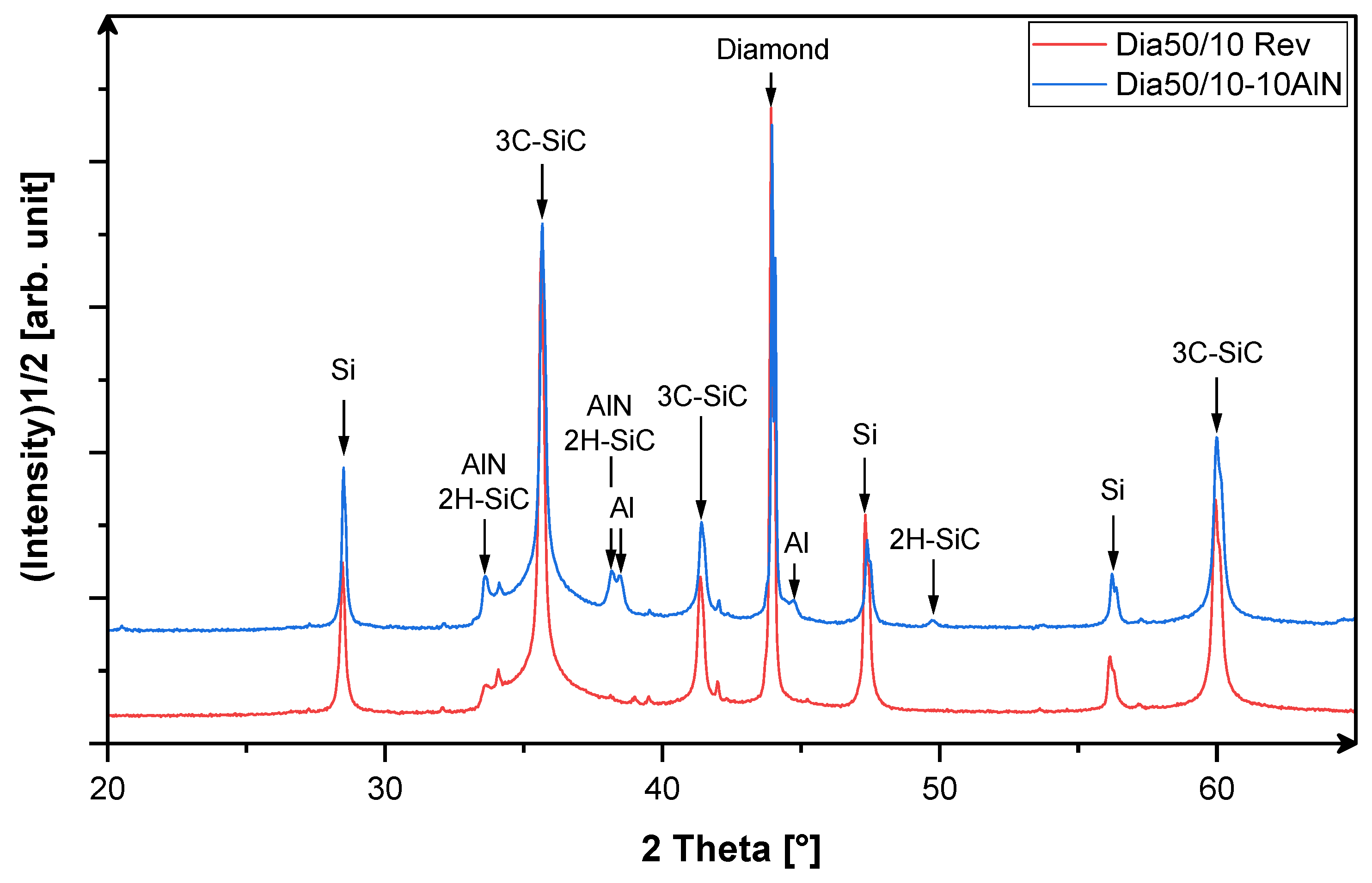
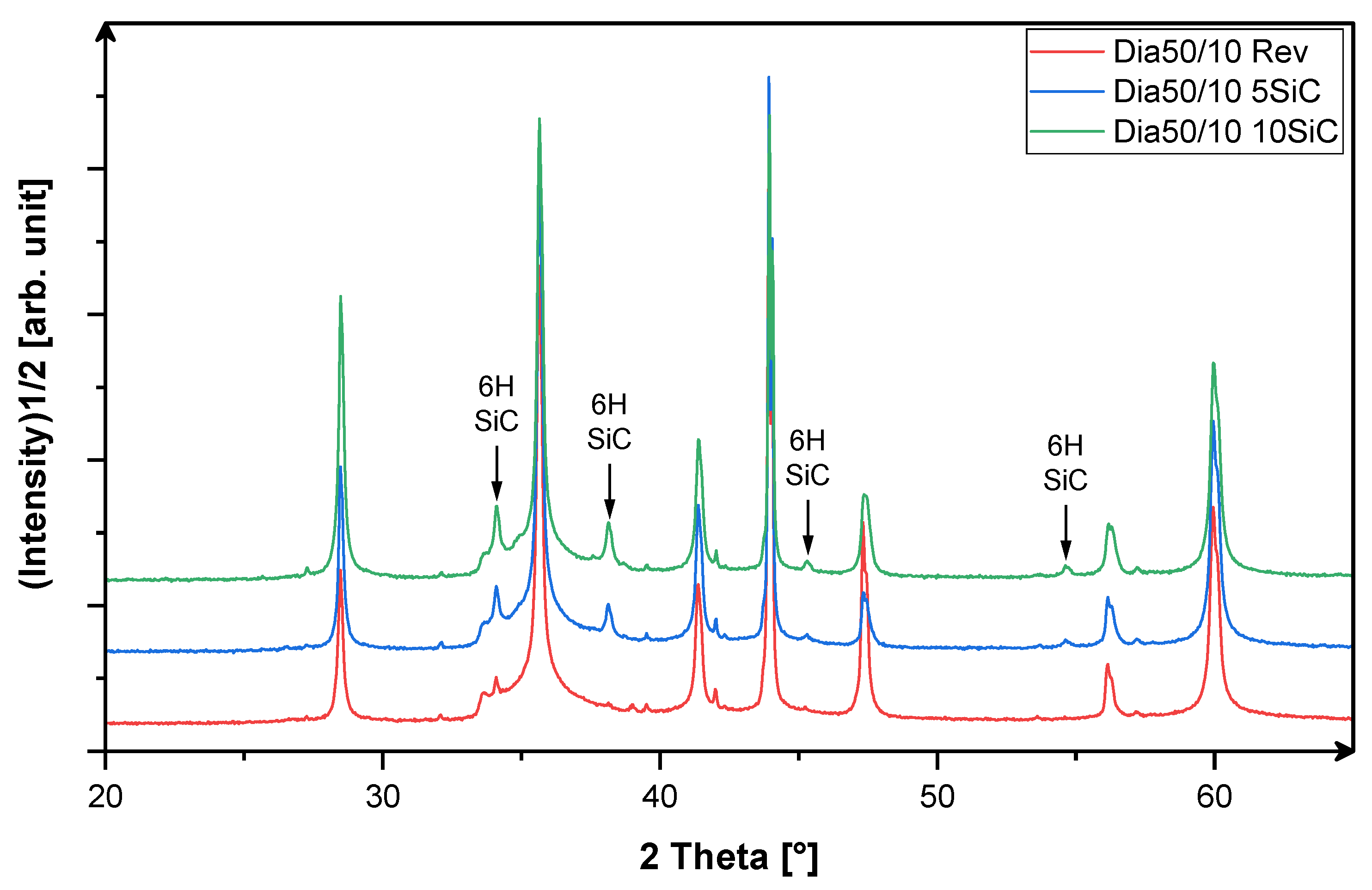
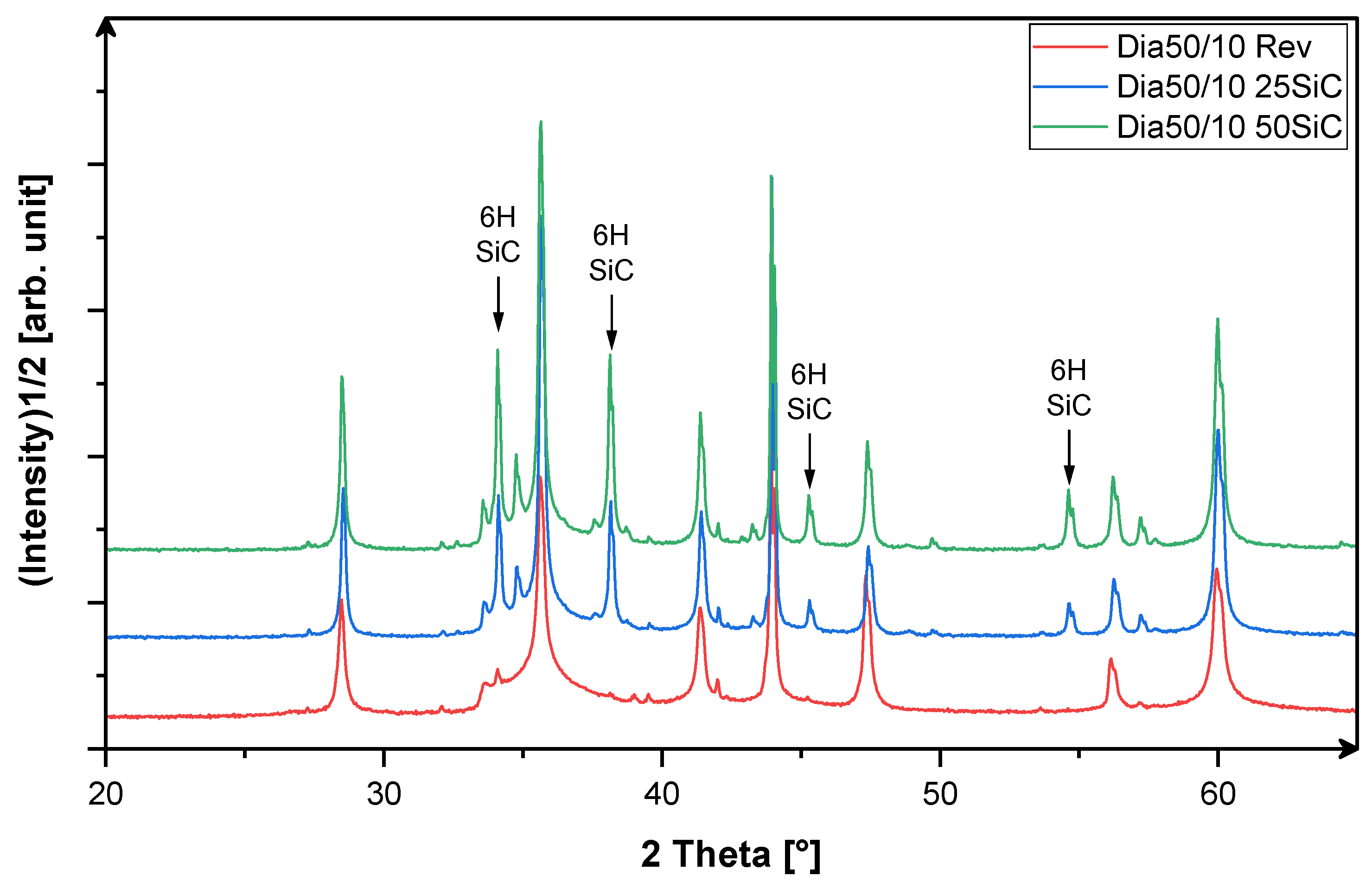
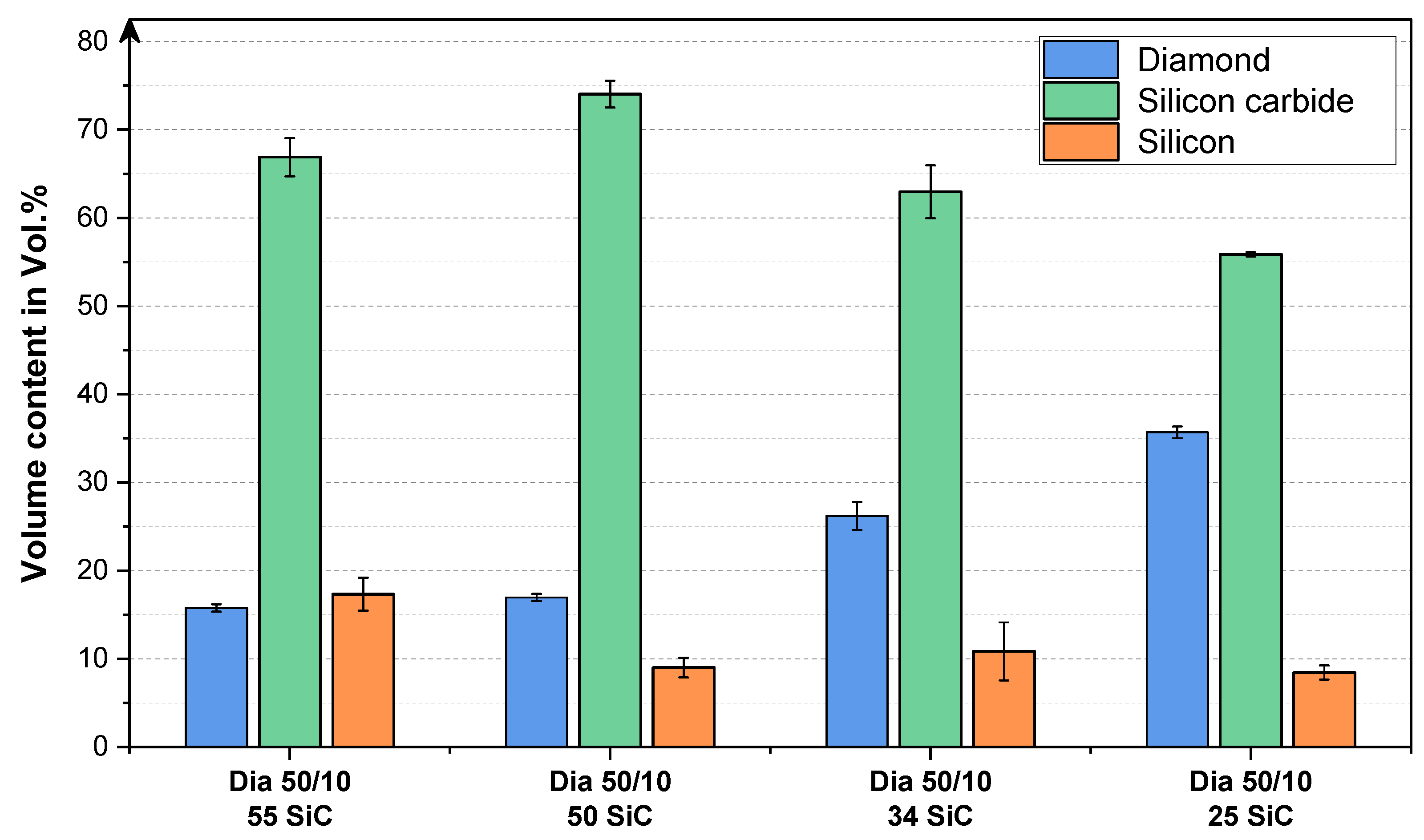
3.1. X-Ray-Phase Analysis

The density and phase composition of the materials are given in Table 2. The data reveal that there is no change in the infiltration due to the addition of SiC particles. In contrast, the material containing AlN has a lower density. This indicates that AlN hinders infiltration. The results of the x-ray phase analysis are summarized in Table 2 and in Figure 1, Figure 2 and Figure 3.
All materials contain diamond, 3C-SiC, and Si as main phases. In the materials with added SiC, a significantly higher proportion of hexagonal polytypes, in particular the 6H-polytype, was found. The quantification of the increase is only possible to a semi-qualitative extent using X-ray diffractometry, as there is a whole series of overlaps. In addition, the stacking faults in the 3C-SiC influence the exact determination [34,35]. Such stacking faults also form, in particular in the vicinity of the diamond-SiC interface [1,28]. Nevertheless, it can be clearly stated that the proportion of hexagonal SiC has increased with the addition of α-SiC powder; it cannot be said with confidence how much of these phases was newly formed during silicification. To understand this, additional investigations of the microstructure are necessary (see next chapter).
The determination of the secondary phases in the material Dia 50/10 10AlN is not fully conclusive, since the peaks of AlN and 2H-SiC overlap. Nevertheless, the small increase of the corresponding peaks indicates that besides 2H-SiC, mostly 3C-SiC must be formed during Si-infiltration.
However, small amounts of the alloy Al0.99Si0.01 were also detected in addition to these phases. This indicates that the AlN phase has at least partially decomposed. Al in the Si melt led to the formation of Al4C3 [28]. The formation of Al4C3 could not be detected here. However, two extremely small peaks at 19.8° and 20.3° 2 theta, which are only detectable in the logarithmic scale of intensity, could indicate the local formation of Al(OH)3 on the sample surface. The hydroxide is the product of the decomposition of Al carbide by atmospheric moisture. However, no changes in the microstructure during storage were observed. To verify the findings, a detailed investigation of the SEM-microstructures is necessary.

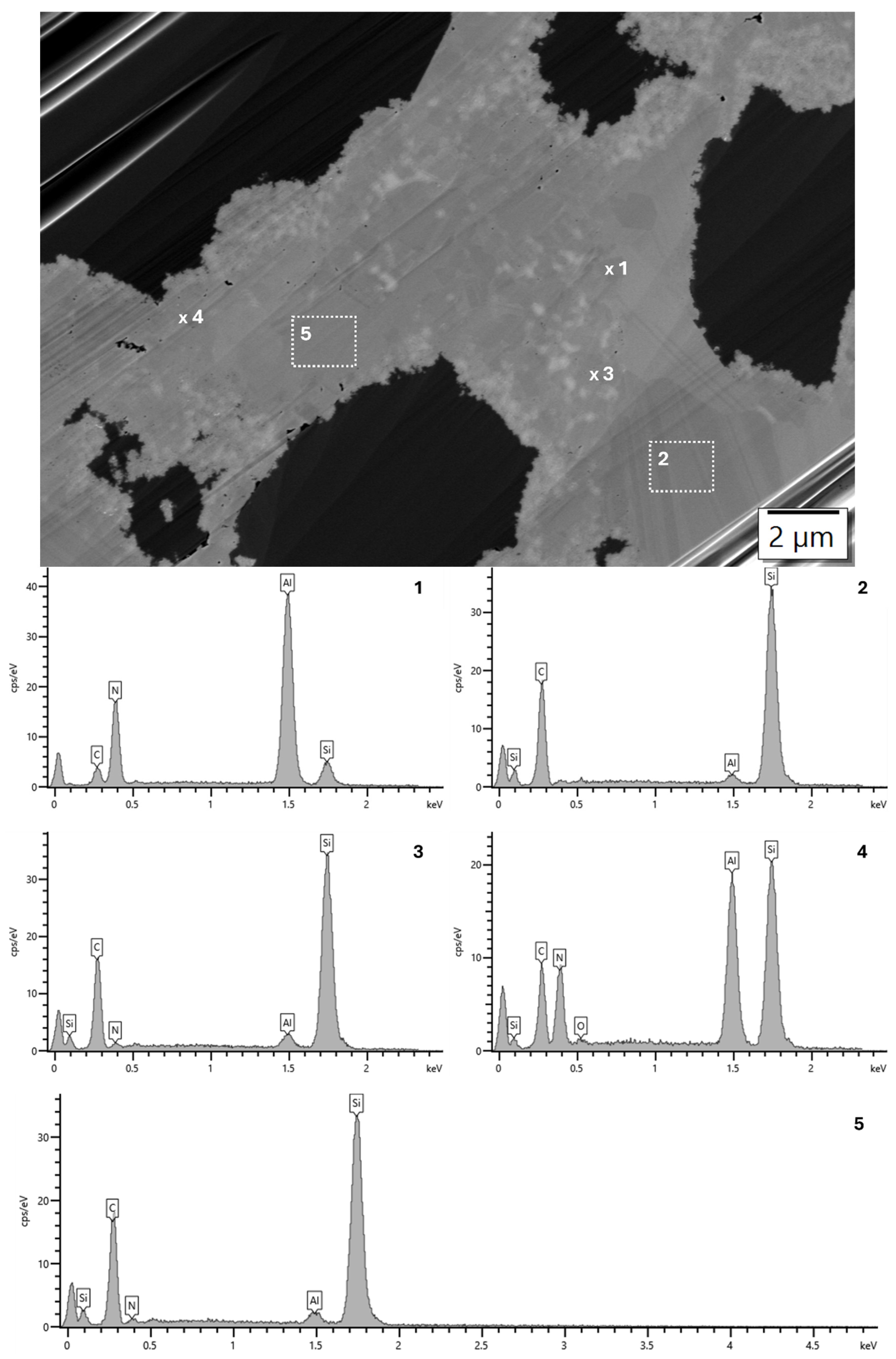
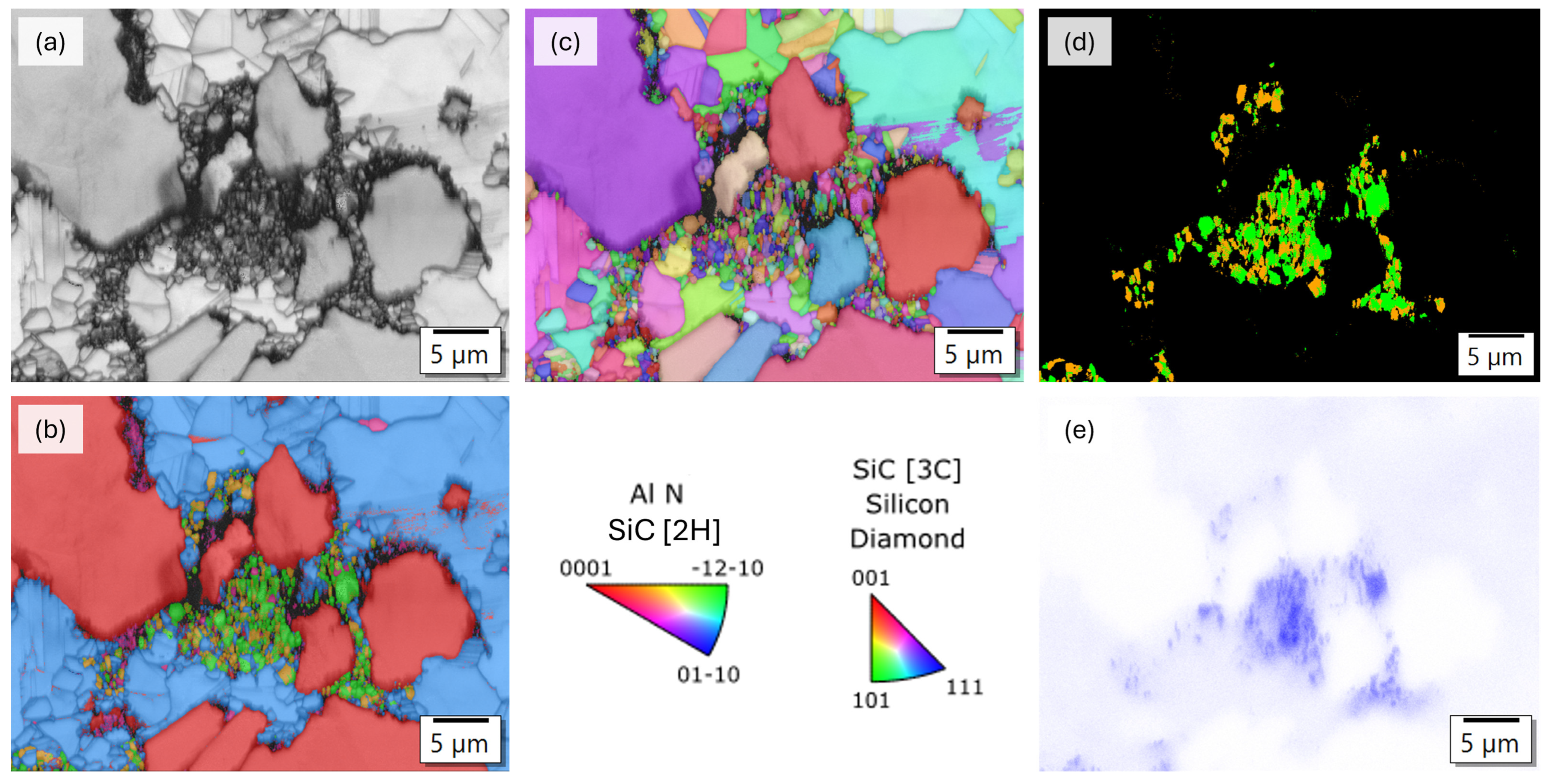
3.2. Analysis of the Microstructure of the AlN Containing Material Dia50/10 10AlN

The microstructure of the sample Dia50/10 10AlN is shown in Figure 4, Figure 5 and Figure 6. At low magnification, there are no abnormalities compared to the standard sample. Besides diamond and SiC, individual Si islands are visible. The higher magnification shows that in addition to the typical, well-faceted SiC particles, individual, rather round particles with diameters between 200 nm and 1 µm are visible. The EDX analysis shows that these particles are AlN grains or solid solutions of AlN with SiC. SiC grows around these AlN grains. Also, larger SiC-grains show a higher amount of stacking faults. The EDX measurement reveals that the larger grains also contain Al in a wide range from nearly 0 to several at.%. If the Al concentration is higher than 1–2 at.%, in addition to the Al signal, nitrogen was also observed. The Al distribution in the SiC-grains is not homogeneous. It looks like it is influenced by the local distribution of the AlN particles in the preform.
In the area where several AlN grains were observed, the grain growth of the SiC at the interfaces seems to be different in comparison to the standard material. The standard materials showed mostly platelet-like SiC crystals parallel to the diamond surface [1]. This is less the case in the sample with AlN. Even the 3C-SiC crystals appear to be more chaotically oriented Figure 4, Figure 5 and Figure 6. The detailed analysis at the interface Diamond-SiC in the area where the AlN was observed near the interface, partially, graphite seems to be formed. This agrees with the observations of Zhang [28], who detected graphite and Al4C3 in Al-contaminated samples at the diamond/SiC interface. This interface showed a low interfacial strength in comparison to Al-free interfaces [28,36,37].
An EBSD analysis was carried out in an area with several AlN grains (Figure 5). The results are shown in Figure 6. The data reveal that, around and in areas where Al (AlN) was found, 2H-SiC grains are formed. While 3C-SiC forms still dominantly at the boundary of the diamond grains. However, the Al concentration (EDX signal) showed in this area a gradient. Therefore, it can be assumed that part of the AlN grains detected in the EBSD are more likely an alumina-rich solid solution 2H-Si1−xAlxC1−xNx. The assignment to AlN and 2H-SiC is therefore probably rather arbitrary at medium Al contents.

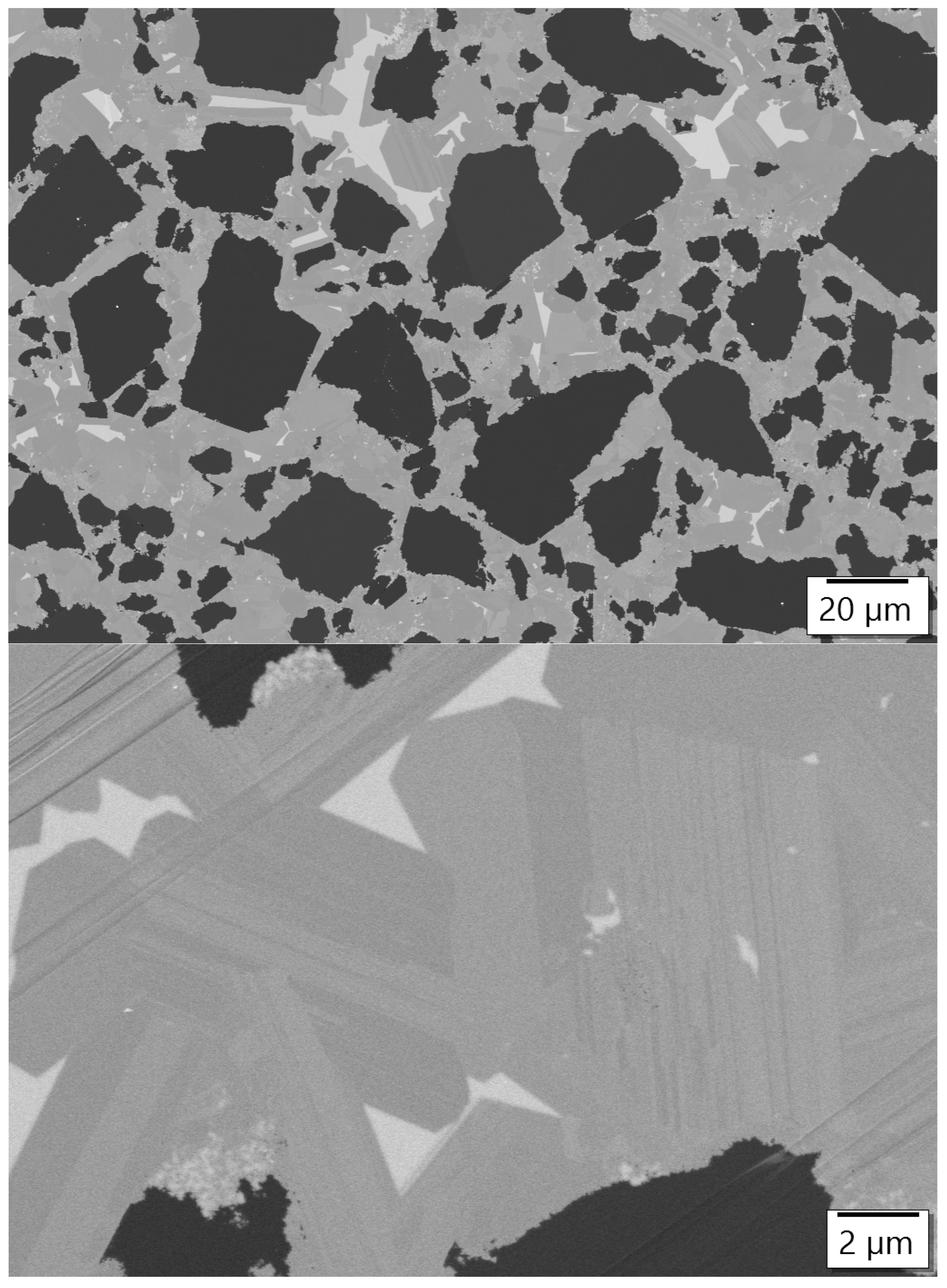
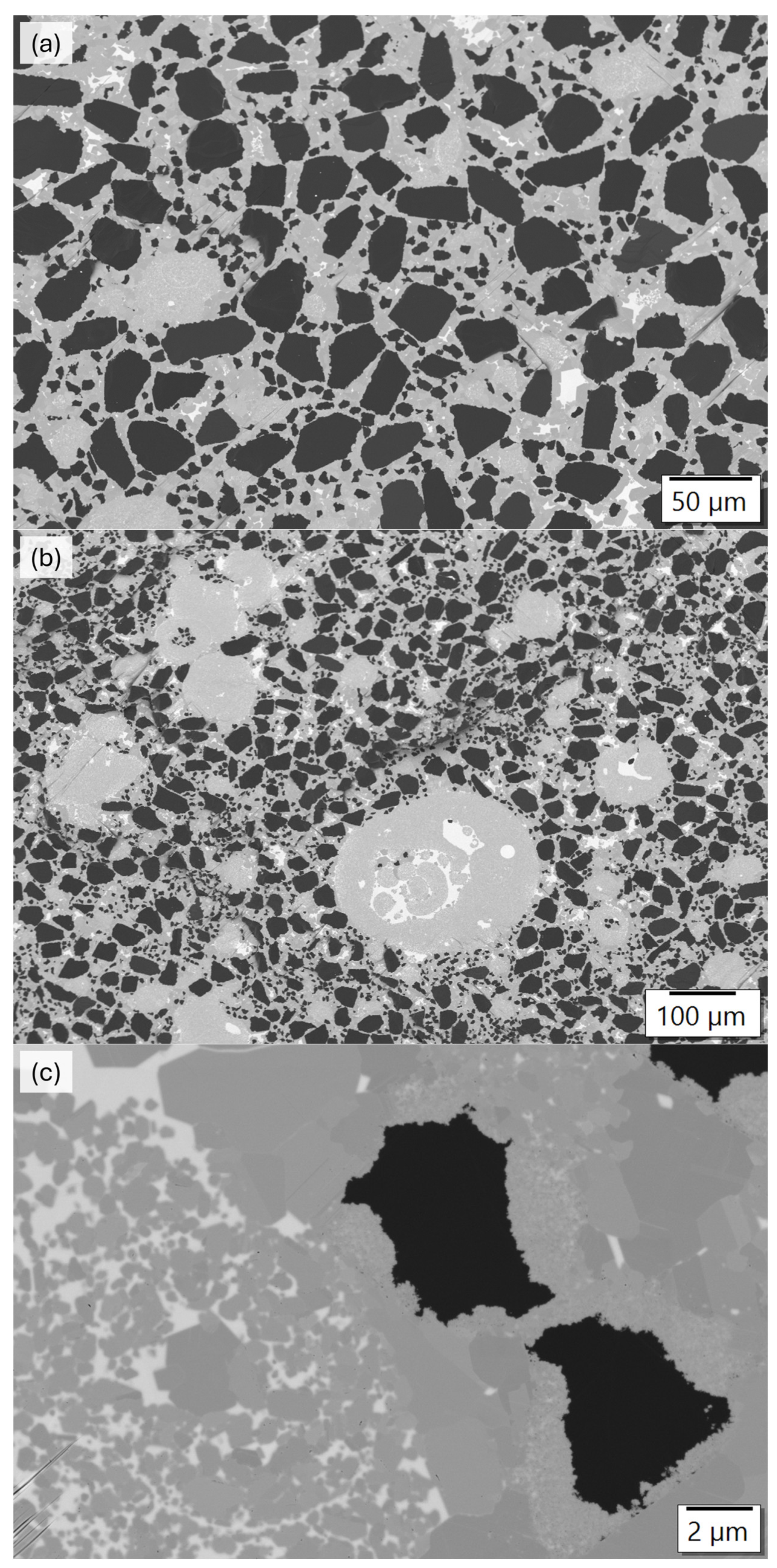
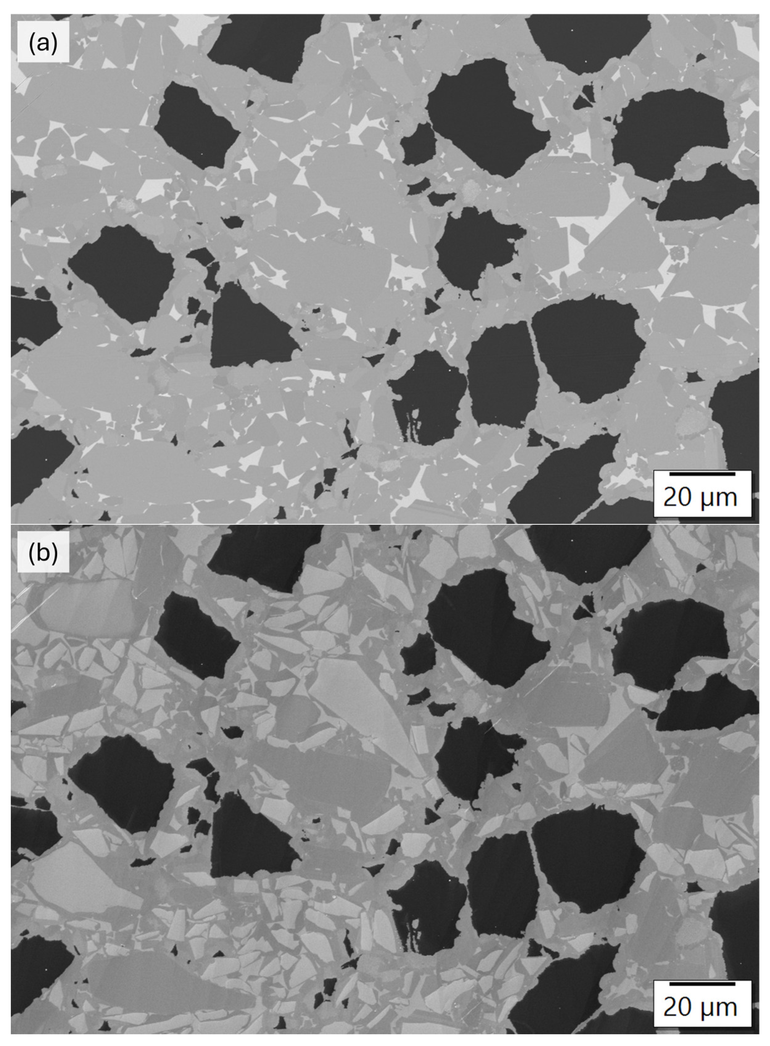
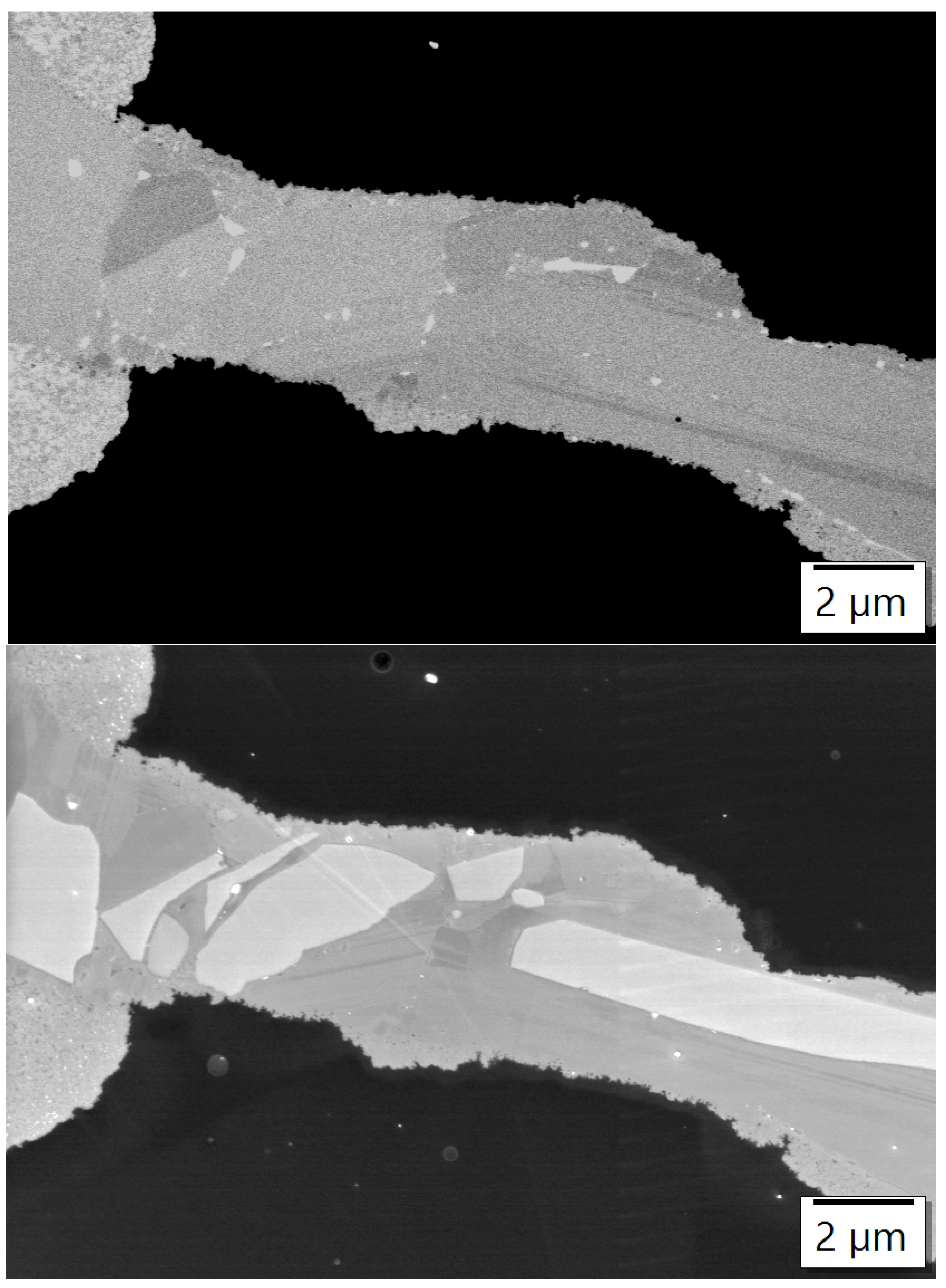
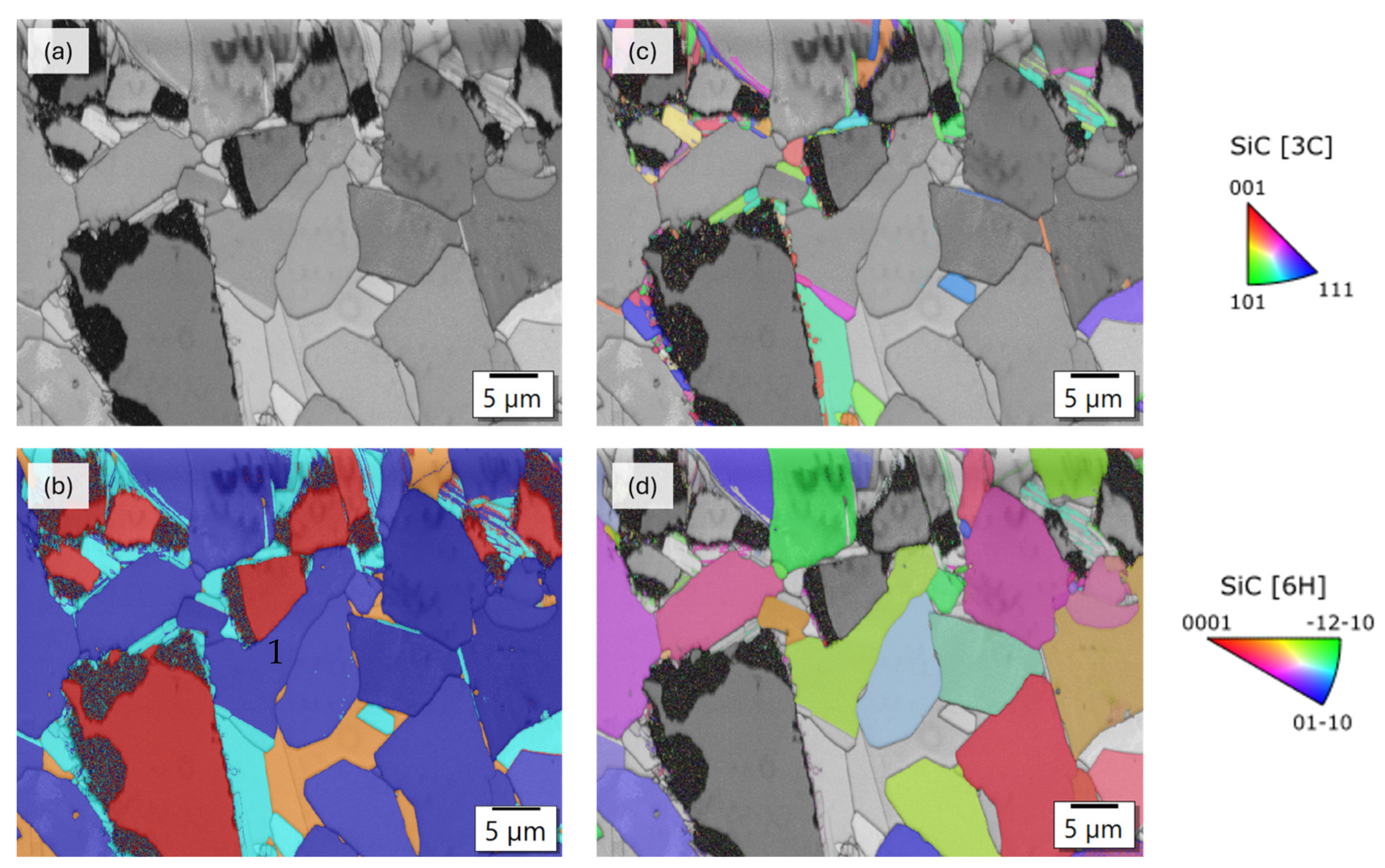
3.3. Analysis of the Microstructure of the SiC Containing Materials
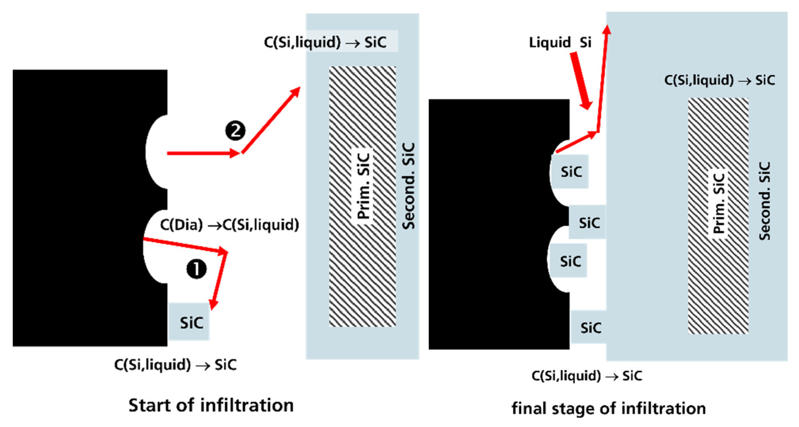
The micrographs of the material Dia 50/10 5SiC and Dia 50/10 10SiC, containing the fine-grained α-SiC, show that the chosen method of powder mixing did not succeed in homogeneously dispersing the fine SiC crystals between the diamonds. The images (Figure 7) show that agglomerates that were present in the raw material UF 15 were transferred to the preform. During silicification, the Si penetrates the pores of the agglomerates and separates the particles partially. It is not possible to determine whether there was any growth of the particles. These samples were therefore not analyzed in detail.
In order to analyze the effect of SiC additions, materials with larger SiC particles (similar grain sizes to diamond) were examined. The results are shown in Figure 8, Figure 9 and Figure 10. Figure 8 shows the images of the microstructure that were recorded with the BSD detector and the SESI detector (Secondary Electrons Secondary Ions Detector). At this magnification, clearly the different phases of diamond, SiC, and Si can be distinguished in the BSD image (Figure 8a). Comparing this image with the image taken with the SESI Detector (Figure 8b), a core-shell structure can be observed in the SiC-grains. This structure documents the primary SiC and secondary SiC. The SiC grains existing in the preform are the primary SiC, and the secondary SiC is the reactively formed SiC that grew on the seeds. Such structures were also found in SiC materials [27]. Figure 9 shows this very clearly at a higher magnification. Additionally, areas with nanocrystalline particles at the interface of diamond/SiC are visible. Such areas were also observed in the standard material; however, in these materials, they are much more pronounced. Figure 10 shows the situation where SiC crystals were pressed between two diamonds in the preform. The images show that the SiC crystals grow in the direction of the diamonds. Thin nanocrystalline boundary layers form at the boundary between the SiC crystal and diamond.
Figure 11 shows the result of the EBSD analysis. The distribution of the phases is clearly visible. Also, a clear distinction between 6H-SiC and 3C-SiC is possible. The 6H-SiC crystals do not show a core-shell structure in the EBSD images. This means that the reactively formed SiC grows in the same polytype and the same orientation as the primary SiC, i.e., the secondary SiC continues the structure of the nucleus. 3C-SiC is dominantly formed near the diamond. This indicates nucleation on the diamond surface or homogeneous nucleation.
The EBSD images also show relatively large areas of nanocrystalline SiC and Si. In these areas, no clear assignment of the phases is possible. These areas are much more pronounced in comparison to the standard material observed earlier [1]. The EBSD also indicates that the crystal orientation of the grown SiC layer around the diamond is less oriented than in the standard material. The addition of α-SiC powder increases the polytype content by growth of the added seeds; however, the volume content of diamond in the composite also reduces, as is shown in Figure 12.

4. Discussion

The added AlN will not decompose by the direct reaction with carbon during heating up to the infiltration temperature.
4AlN+ 3C ⇨ Al4C3 + 2N2 ΔG (1400 °C) = 429.3 kJ/mol
This can be concluded from the high positive value of ΔG (1400 °C) of the reaction [Factsage8.3]. The native Al2O3-surface layer on the AlN-grains is also quite stable and is only slowly removed by the following reaction:
Al2O3 + 2C ⇨ Al2O + 2CO
The resulting CO partial pressure at 1600 °C is only 8 × 10⁻³ atm. This could be a reason for the difficulties in the infiltration of the samples.
The solubility of Al in liquid silicon at 1500–1600 °C is relatively low. Thermodynamic calculations show that at a local nitrogen pressure of 10−3 atm, approx. 5 at.-% Al dissolves in equilibrium in the silicon melt at 1600 °C. At a pressure of 10−2 atm N2, only 1.6 at.-% Al is dissolved. It is not possible to clearly predict the exact pressure that will build up in the pore channels of the preform. However, the results show that AlN partially dissolves in the melt, and part of the N2 goes into the gas phase. This explains why Al was also found in larger SiC-grains. It was incorporated directly from the melt during the formation of the SiC-grains. It can therefore be assumed that the added AlN particles can serve as nuclei for 2H-SiC. It forms a solid solution 2H-Si1−xAlxC1−xNx and doped Si1−xAlXC1−3/4x with a lower Al concentration. The latter could also be the 3C-SiC phase. However, it looks like the number of stacking faults has increased. The 3C SiC is still predominantly formed in the material. This indicates that diamond is an equally good nucleus for 3C SiC and has many nucleating sites.
Using large AlN grains could at least partially change the situation, because they dissolve more slowly and may be more effective seeds. Regardless of this, the hindrance of silicification remains. Al2O3 exhibits a contact angle of 86–93°, and AlN has a wetting angle of 50–60° at Si-melting temperature. These values are much higher than for diamond and SiC and therefore strongly reduce the capillary forces [38,39].
In the investigated SiC material with the high SiC content, most of the newly formed SiC is precipitated on the existing α-SiC seeds. The formed SiC continues the structure of the α-SiC nucleus. Nevertheless, 3C-SiC is primarily formed near the diamond surface. This indicates nucleation on the diamond surface or homogeneous nucleation, in addition to the growth of the α-SiC seeds. The dissolution of the diamond into liquid Si takes place and generates the rough surface as shown earlier [1,39]. The local carbon concentration is higher than the equilibrium concentration.
Si (melt) + C (Si melt) ⇨ SiC(solid)
Therefore, the carbon will diffuse through the liquid and precipitate as SiC. There are two ways for precipitation. The first way (1 in Figure 13) is the path, which is dominant in pure diamond preforms: heteroepitaxial nucleation of SiC on the surface of diamond. There is an energy barrier for SiC-nucleation at the interface. Therefore, an initially high degree of supersaturation is necessary to enable nucleation. If the diffusion of carbon through the melt to the SiC-grains (path 2 in Figure 13) is fast, then the large α-SiC-crystals grow. The large α-SiC-crystals have a lower carbon equilibrium concentration in the melt than the nanocrystalline nuclei. Therefore, in the case of fast diffusion and slow dissolution of diamond, the concentration of carbon is below the critical value for nucleation and growth at the diamond surface. This means that pathway 2 is the dominant one. In the final phase of growth, the transport processes in the narrow gap between diamond and SiC are slower, and the formation of nanocrystalline SiC in the interface regions can occur. Path 1 is more pronounced. However, the reaction space is limited by diamond and large α-SiC grains, and the transport of Si into this space is restricted. Therefore, this reaction also stops before the complete conversion of the diamond. This change of the reaction path is probably favored by different growth rates of the basal and prismatic surfaces of the hexagonal SiC grains.
If a large grain is directly attached to the diamond surface during shaping the preform, only reaction path 2 can be active at this point. This seems to be the case for grain 1 in Figure 11. Regardless of this, 3C-SiC crystals can also be detected locally in the vicinity of diamond, which indicates that locally, diamond can indeed function as a nucleating agent for larger crystals. The ratio of the two reaction pathways depends on the local distribution of the diamond and SiC. Smaller, well-distributed SiC grains lead to shorter diffusion paths, which should strengthen reaction path 2, but they also have a slightly higher equilibrium concentration. Therefore, additional investigations based on materials with different contents and SiC grain sizes are necessary to better understand the mechanism of controlling the microstructures and their influence on the properties.
The consequence of the changed SiC growth is that the diamond is differently bonded to the SiC-matrix in comparison to the materials produced from the pure diamond preform. If this has an influence on the wear resistance or the thermal properties, it must be investigated. At least the thermal conductivity data of the materials with increasing SiC content reduces (Table 2). However, this could be mostly caused by the reduction of the diamond content.

5. Conclusions

The investigations on the doped diamond SiC materials show that both AlN and SiC act as a growth nucleus for hexagonal SiC. However, there is still nucleation and growth of 3C-SiC crystals on the diamond surface. The investigations have shown that AlN serves as a nucleus for 2H-SiC crystals. Additionally, it at least partially dissolves in the melt and dopes the SiC-grains. However, due to the poor wetting of the AlN and the Al2O3 surface layers of AlN by the Si, the infiltration is worsened. Therefore, AlN is not necessarily well suited as a seed for α-SiC in the reactively infiltrated materials.
SiC-crystals do not lead to a deterioration of the infiltration, which was to be expected. The added seeds continue to grow in the form of a hexagonal polytype of the seed. In the materials with the higher concentration of SiC seeds, the SiC was largely deposited on these nuclei. The heterogeneous epitaxial nucleation of the SiC on the diamond surface appears to be partially suppressed. This also leads to larger areas with nanocrystalline SiC at the diamond/SiC interface than in the materials made of pure diamond preforms.
Further investigations are necessary to understand the influence of SiC particle size and concentration on the microstructure and properties.

Author Contributions

Conceptualization, M.H. and B.M.; methodology, M.H., B.M. and S.H.; validation and methodology, M.H., B.M., J.A.Q.F. and S.H.; investigation, J.A.Q.F., S.H., B.M., S.K. and M.H.; writing—original draft preparation, M.H.; writing—reviewing and editing, J.A.Q.F. and S.H.; visualization, J.A.Q.F., M.H., B.M. and S.H.; supervision, M.H.; project administration, M.H.; funding acquisition, M.H. All authors have read and agreed to the published version of the manuscript.

Funding

This work was mostly sponsored by the Army Research Office and was accomplished under the Cooperative Agreement Number W911NF-20-2-0115. The views and conclusions contained in this document are those of the authors and should not be interpreted as representing the official policies, either expressed or implied, of the Army Research Office or the U.S. Government. The U.S. Government is authorized to reproduce and distribute reprints for Government purposes, notwithstanding any copyright notation herein.

Institutional Review Board Statement

Not applicable.

Informed Consent Statement

Not applicable.

Data Availability Statement

The original contributions presented in this study are included in the article. Further inquiries can be directed to the corresponding author.

Acknowledgments

During the preparation of this work, the authors used [https://www.deepl.com/de/translator] in order to improve the English language. After using this tool/service, the authors reviewed and edited the content as needed and take full responsibility for the content of the publication.

Conflicts of Interest

The work was mostly sponsored by the Army Research Office and was accomplished under the Cooperative Agreement Number W911NF-20-2-0115. The funders involved had no role in the design of this study; in the collection, analysis, or interpretation of data; in the writing of the manuscript; or in the decision to publish the results. The views and conclusions contained in this document are those of the authors and should not be interpreted as representing the official policies, either expressed or implied, of the Army Research Office or the U.S. Government. The U.S. Government is authorized to reproduce and distribute reprints for Government purposes, notwithstanding any copyright notation herein.

References

  1. Matthey, B. Siliciumcarbid Gebundene Diamantwerkstoffe—Herstellung. Mikrostruktur und Eigenschaften. Ph.D. Thesis, Technische Universität Dresden, Dresden, Germany, 2018. [Google Scholar]
  2. Gordeev, S.; Zhukov, S.; Danchukova, L.; Ekstrom, T. Low-Pressure Fabrication of Diamond–SiC–Si Composites. Inorg. Mater. 2001, 6, 579–583. [Google Scholar] [CrossRef]
  3. Matthey, B.; Kunze, S.; Hörner, M.; Blug, B.; van Geldern, M.; Michaelis, A.; Herrmann, M. SiC-bonded diamond materials produced by pressureless silicon infiltration. J. Mater. Res. 2017, 17, 3362–3371. [Google Scholar] [CrossRef]
  4. Yang, Z.; He, X.; Wu, M.; Zhang, L.; Ma, A.; Liu, R.; Hu, H.; Zhang, Y.; Qu, X. Infiltration mechanism of diamond/SiC composites fabricated by Si-vapor vacuum reactive infiltration process. J. Eur. Ceram. Soc. 2013, 4, 869–878. [Google Scholar] [CrossRef]
  5. Yang, Z.; He, X.; Wu, M.; Zhang, L.; Ma, A.; Liu, R.; Hu, H.; Zhang, Y.; Qu, X. Fabrication of diamond/SiC composites by Si-vapor vacuum reactive infiltration. Ceram. Int. 2013, 3, 3399–3403. [Google Scholar] [CrossRef]
  6. Shevchenko, V.Y.; Dolgin, A.; Sychov, M.M.A.; Perevislov, S. Ideal: A promising diamond-silicon carbide composite for enhanced amor. Ceram. Int. 2024, 50, 4264–4273. [Google Scholar] [CrossRef]
  7. Shevchenko, V.; Perevislov, S. Reaction–Diffusion Mechanism of Synthesis in the Diamond–Silicon Carbide System. Russ. J. Inorg. Chem. 2021, 66, 1107–1114. [Google Scholar] [CrossRef]
  8. Bogdanov, S.P.; Dolgin, A.S.; Perevislov, S.N.; Khristyuk, N.A.; Sychov, M.M. Effect of Diamond Phase Dispersion on the Properties of Diamond-SiC-Si Composites. Ceramics 2023, 6, 1632–1645. [Google Scholar] [CrossRef]
  9. Zhang, Z.; He, X.; Zhang, T.; Liu, P.; Qu, X. Preparation of bimodal-diamond/SiC composite with high thermal conductivity. J. Eur. Ceram. Soc. 2024, 44, 643–650. [Google Scholar] [CrossRef]
  10. Schmalzried, C.; Schwetz, K.A. Silicon-Carbide-and Boron Carbide-Based Hard Materials. In Ceramics Science and Technology; John Wiley & Sons: Hoboken, NJ, USA, 2010; pp. 131–227. [Google Scholar]
  11. Madelung, O.; Rössler, U.; Schulz, M. (Eds.) Landolt-Börnstein—Group III Condensed Matter: Numerical Data and Functional Relationships in Science and Technology; Springer: Berlin/Heidelberg, Germany, 2002. [Google Scholar] [CrossRef]
  12. Gmelin Handbook of Inorganic and Organometallic Chemistry, 8th ed.; Springer: Berlin/Heidelberg, Germany, 1984; Silicon Volume B2.
  13. Ruys, A.J. Silicon Carbide Ceramics: Structure, Properties and Manufacturing; Elsevier: Amsterdam, The Netherlands, 2023; p. 89. [Google Scholar]
  14. Grinchuk, P.S.; Abuhimd, H.M.; Kiyashko, M.V. Advanced reaction-bonded SiC ceramics for space mirror blanks. J. Manuf. Process. 2024, 113, 275–290. [Google Scholar] [CrossRef]
  15. Oleinik, G.S.; Danilenko, N.V. Polytype formation in nonmetallic substances. Russ. Chem. Rev. 1997, 66, 553. [Google Scholar] [CrossRef]
  16. Xu, W.-W.; Xia, F.; Chen, L.; Wu, M.; Gang, T.; Huang, Y. High-temperature mechanical and thermodynamic properties of silicon carbide polytypes. J. Alloys Compd. 2018, 768, 722–732. [Google Scholar] [CrossRef]
  17. Luo, X.; Goel, S.; Reuben, R.L. A quantitative assessment of nanometric machinability of major polytypes of single crystal silicon carbide. J. Eur. Ceram. Soc. 2012, 32, 3423–3434. [Google Scholar] [CrossRef]
  18. Prasad, K.E.; Ramesh, K.T. Hardness and mechanical anisotropy of hexagonal SiC single crystal polytypes. J. Alloys Compd. 2019, 770, 158–165. [Google Scholar] [CrossRef]
  19. Eddy, C.R.; Wu, P.; Zwieback, I.; VanMil, B.L.; Myers-Ward, R.L.; Tedesco, J.L. Microhardness of 6H-and 4H-SiC Substrates. Mater. Sci. Forum. 2009, 615–617, 323–326. [Google Scholar] [CrossRef]
  20. Sugiyama, S.; Togaya, M. Phase Relationship between 3C- and 6H-Silicon Carbide at High Pressure and High Temperature. J. Am. Ceram. Soc. 2001, 84, 3013–3016. [Google Scholar] [CrossRef]
  21. Atkinson, C.M.; Guziewski, M.C.; Coleman, S.P.; Nayak, S.K.; Alpay, S.P. First principles analysis of impurities in silicon carbide grain boundaries. Acta Mater. 2021, 221, 117421. [Google Scholar] [CrossRef]
  22. Kuang, J.; Cao, W. Elder Synthesis of α-SiC particles at 1200 °C by microwave heating. Powder Technol. 2013, 247, 106–111. [Google Scholar] [CrossRef]
  23. Wei, S.; Guan, L.; Song, B.; Fan, B.; Zhao, B.; Zhang, R. Seeds-induced synthesis of SiC by microwave heating. Ceram. Int. 2019, 45, 9771–9775. [Google Scholar] [CrossRef]
  24. Turan, S.; Knowles, K.M. Effect of Boron Nitride on the Phase Stability and Phase Transformations in Silicon Carbide. J. Am. Ceram. Soc. 1996, 79, 3325–3328. [Google Scholar] [CrossRef]
  25. Mainzer, B. How to Tame the Aggressiveness of Liquid Silicon in the LSI Process. Key Eng. Mater. 2017, 742, 238–245. [Google Scholar] [CrossRef]
  26. Quintana Freire, J.A.; Matthey, B.; Höhn, S.; Kunze, S.; Herrmann, M. Boron Containing SiC Bonded Diamond Composites. Fraunhofer Institute for Ceramic Technologies and Systems, Dresden, Germany. 2025; manuscript in preparation. [Google Scholar]
  27. Herrmann, M.; Sempf, K.; Kremmer, K.; Schneider, M.; Michaelis, A. Electrochemical corrosion of silicon-infiltrated silicon carbide ceramics in aqueous solutions. Ceram. Int. 2015, 41, 4422–4429. [Google Scholar] [CrossRef]
  28. Zhang, Y.; Hsu, C.-Y.; Karandikar, P.; Ni, C. Interfacial zone surrounding the diamond in reaction bonded diamond/SiC composites: Interphase structure and formation mechanism. J. Eur. Ceram. Soc. 2019, 39, 5190–5196. [Google Scholar] [CrossRef]
  29. Park, J.H.; Kim, D.J.; Kim, S.W.; Youm, M.R.; Nahm, S.; Park, S.W. Effects of diamond as a main carbon source on the fabrication and mechanical properties of reaction-bonded SiC. Ceram. Int. 2024, 50, 35169–35177. [Google Scholar] [CrossRef]
  30. Mlungwane, K. A Study on the Sintering of fine-Grained Diamond-SiC Composites. Ph.D. Thesis, University of Witwatersrand, Johannesburg, South Africa, 2014. [Google Scholar]
  31. Kunze, S.; Matthey, B.; Herrmann, M. SiC-bonded diamond material with excellent abrasive wear resistance. Open Ceram. 2024, 19, 100627. [Google Scholar] [CrossRef]
  32. Matthey, B.; Kunze, S.; Kaiser, A.; Herrmann, M. Thermal properties of SiC-bonded diamond materials produced by liquid silicon infiltration. Open Ceram. 2023, 15, 100386. [Google Scholar] [CrossRef]
  33. DIN EN ISO 18754:2022-06; Hochleistungskeramik- Bestimmung der Dichte und der scheinbaren Porosität. Deutsches Institut für Normung (German Institute for Standardization): Berlin, Germany, 2022.
  34. Pujar, V.V.; Cawley, J.D. Computer Simulations of Diffraction Effects due to Stacking Faults in β-SiC: I, Simulation Results. J. Am. Ceram. Soc. 1997, 80, 1653–1662. [Google Scholar] [CrossRef]
  35. Pujar, V.V.; Cawley, J.D. Computer Simulations of Diffraction Effects due to stacking faults in β-SiC: II, Experimental Verification. J. Am. Ceram. Soc. 2001, 84, 2645–2651. [Google Scholar] [CrossRef]
  36. Zhang, Y.; Hsu, C.; Wang, T.; Karandikar, P.; Ni, C. Mechanical and thermal characteristics of interfaces and defects in diamond/SiC composites (Invited). In Proceedings of the 44th ICACC, Daytona Beach, FL, USA, 29 January 2020. ICACC-S4-030-2020. [Google Scholar]
  37. Yousefi, P.; Matthey, B.; Fontanot, T.; Herre, P.; Höhn, S.; Christiansen, S.H.; Herrmann, M. Strength of diamond-silicon carbide interfaces in silicon carbide bonded diamond materials containing graphitic interlayers. Open Ceram. 2022, 11, 100296. [Google Scholar] [CrossRef]
  38. Drevet, B.; Eustathopoulos, N. Wetting of ceramics by molten silicon and silicon alloys: A review. J. Mater. Sci. 2012, 47, 8247–8260. [Google Scholar] [CrossRef]
  39. Mlungwane, K.; Sigalas, I.; Herrmann, M.; Rodrıguez, M. The wetting behaviour and reaction kinetics in diamond–silicon carbide systems. Ceram. Int. 2009, 35, 2435–2441. [Google Scholar] [CrossRef]
Figure 1. XRD-pattern of the material with AlN addition (Dia 50/10-10AlN) in comparison to the reference Dia50/10 Rev.
Ceramics 08 00090 g001
Figure 2. XRD pattern of the material with 5 and 10 wt.% addition of SiC (UF 15) in comparison to the reference Dia50/10 Rev.
Ceramics 08 00090 g002
Figure 3. XRD pattern of the material with 25 and 50 wt.% addition of SiC (UF 15) in comparison to the reference Dia50/10 Rev.
Ceramics 08 00090 g003
Figure 4. FE-SEM microstructure of the material Dia50/10 10AlN at different magnifications.
Ceramics 08 00090 g004
Figure 5. Results of EDX analysis of the material Dia50/10 10AlN.
Ceramics 08 00090 g005
Figure 6. Results of local EBSD analysis (a) band contrast, (b) phase mapping (diamond: red; 3C SiC: blue; AlN: green; 2HSiC: ocher), (c) orientation mapping, (IPF-z) (d) mapping of only AlN (green) and 2H-SiC (ocher), (e) EDX signal of Al.
Ceramics 08 00090 g006
Figure 7. (ac) FE-SEM microstructure of the material Dia50/10 10SiC at different magnifications.
Ceramics 08 00090 g007
Figure 8. FE-SEM microstructure of the material Dia50/10 50 SiC with BSD (a) and SESI detector (b).
Ceramics 08 00090 g008
Figure 9. FE-SEM microstructure of the material Dia50/10 50 SiC, clearly showing the core rim structure.
Ceramics 08 00090 g009
Figure 10. FE-SEM microstructure of the material Dia 50/10 50 SiC ESB and IN-LENS detector.
Ceramics 08 00090 g010
Figure 11. Results of the EBSD analysis of the material Dia50/10 50 SiC (a) Band contrast showing the nanocrystalline areas at the diamond interface (black area) (b) Phase mapping (diamond red; 3C SiC light blue; 6H SiC dark blue and Si (orange). The darker marks on the top are related to defects from the ion beam polishing. Orientation maps of the 6H and the 3C phase are color-coded separately as IPF-z Orientation (c,d).
Ceramics 08 00090 g011
Figure 12. Phase composition determined by quantitative image analysis.
Ceramics 08 00090 g012
Figure 13. Schematic representation of the growth process The red arrows schematically show transport routes.
Ceramics 08 00090 g013
Table 1. Properties of the different SiC polytypes [10,12,17] (Z is the number of molecules in the unit cell).
Polytype (Ramsdell
Notation)
Layer SequencySpace GroupZLattice ParameterBand Gap, eVE, GPaH (100) Plane, GPa
a, nmc, nm
3CABCF43m40.43590 2.331425–30
2HABP63mc20.307900.50553.3
4HABCBP63mc40.308001.00803.234726
6HABCACBP63mc60.308061.51173.034720–26
Table 2. Conditions of preparation and composition of the prepared materials.
Additives Density, g/cm3Open
Porosity, %
Phase ContentTemperature Conductivity,
mm2/s
Thermal Conductivity,
W/m∗K
Dia 50/10 Rev-1575 °C
20 min
3.290Diamond, Si, 3C-SiC218.4439
Dia 50/10 10AlN10 wt. % AlN1575 °C
20 min
3.124.5Diamond, 3C-SiC, 2H-SiC, AlN, Si, Al; Al(OH)396.0approx. 180
Dia 50/10 5SiC5 wt. % SiC UF151575 °C
20 min
3.320Diamond, Si3C-SiC, 6HSiC213.3433
Dia 50/10 10SiC10 wt. % SiC UF151575 °C 20 min3.300Diamond, Si, 3C-SiC 6HSiC184.0370
Dia 50/10 55 SiC55 SiC F900/F3601600 °C 60 min3.190Diamond, Si, 3C-SiC, 6H-SiC
Dia 50/10 50 SiC 50 SiC F900/F3601600 °C 60 min3.190Diamond, Si 3C-SiC, 6H-SiC
Dia 50/10 34SiC34 SiC F900/F3601600 °C 60 min3.260Diamond, Si 3C-SiC, 6H-SiC
Dia 50/10 25-SiC25 SiC F900/F3601600 °C 60 min3.260Diamond, Si 3C-SiC, 6H-SiC
Disclaimer/Publisher’s Note: The statements, opinions and data contained in all publications are solely those of the individual author(s) and contributor(s) and not of MDPI and/or the editor(s). MDPI and/or the editor(s) disclaim responsibility for any injury to people or property resulting from any ideas, methods, instructions or products referred to in the content.

