Article

Effect of Fe2O3 on Compressive Strength and Microstructure of Porous Acicular Mullite

1
Vinča Institute of Nuclear Sciences, National Institute of the Republic of Serbia, University of Belgrade, 11000 Belgrade, Serbia
2
State Key Lab of New Ceramic Materials, School of Materials Science and Engineering, Tsinghua University, Beijing 100084, China
*
Authors to whom correspondence should be addressed.
Ceramics 2025, 8(3), 111; https://doi.org/10.3390/ceramics8030111
Submission received: 9 August 2025 / Revised: 2 September 2025 / Accepted: 4 September 2025 / Published: 5 September 2025
(This article belongs to the Special Issue Ceramic Materials for Industrial Decarbonization)

Abstract

Porous acicular mullite was fabricated at 1300 °C starting from Al2O3 and mixture of SiO2 and MoO3 obtained by previous oxidation of waste MoSi2. It was found that the presence of MoO3 favors formation of acicular (prism-like) mullite grains with sharp edges. The effect of addition of Fe2O3 (4–12 wt.%) on phase composition, compressive strength, thermal conductivity and microstructure was studied. The addition of Fe2O3 improved the compressive strength from approximately 25 MPa in pure mullite to about 76 MPa in samples containing 12 wt.% Fe2O3, while the open porosity decreased from 55.4% to 51.8%. The presence of Fe2O3 caused a decrease in mullite formation temperature owing to the formation of liquid phase and accelerated diffusion. The solubility of iron oxide in mullite lattice was between 8 and 12 wt.% Fe2O3. The incorporated iron ions also promoted the rounding of sharp edges in prismatic mullite grains, leading to a reduced specific surface area of 0.55 m2/g in the sample with 12 wt.% Fe2O3. The thermal conductivity of mullite increased with addition of 12 wt.% Fe2O3 reaching value of 1.17 W/m·K.

1. Introduction

Porous acicular mullite (3Al2O3·2SiO2) is a promising material for hot gases filtration owing to its excellent combination of thermal properties, such as good thermal shock resistance, low thermal expansion coefficient and good stability at elevated temperature [1,2]. Although filter materials are usually not exposed to considerable mechanical load, a sufficiently good rigidity is essential to allow easy handling and machining. Acicular (needle-like) mullite consisting of elongated, interlocked grains typically possesses a much better rigidity/porosity ratio than material consisting of equiaxed grains [3,4]. In addition, acicular microstructure creates unusually low pressure drop across the filter which is especially important for filtration of diesel engine exhaust [5]. Therefore, it has been essential to fabricate acicular mullite using an inexpensive method and cheap starting material such as kaolinite [6], which mainly consists of Al2O3 and SiO2. Developing prism-like, elongate, mullite grains using conventional ceramic processing techniques has been found to be quite difficult. This unique grain morphology is normally developed using expensive techniques, which involve grain growth from either molten phase [7,8] or gaseous phase [9,10]. The Dow Chemical Company, Core R&D, Midland, USA developed acicular mullite in a reactor filled with SiF4 [10]. Kaolinite clay as a starting material was first transformed into fluorotopaz as an intermediate product, which was subsequently transformed into acicular mullite. The process was conducted under careful monitoring of the SiF4 gas flow. However, a similar microstructure was obtained in our previous study using a simple and inexpensive technique [11]. It was shown that waste MoSi2 can be used as both a source of SiO2 and a pore former. The oxidation (calcination) of crushed and pulverized waste MoSi2 heating elements is given by the following Equation (1) [12]:
2MoSi2 (s) + 7O2 (g) → 2MoO3 (s) + 4SiO2 (s)
Thus, MoO3 evaporates before the onset of the sintering process, creating additional porosity. The presence of a pore-forming agent is especially important for filter application, as required porosity is very high, typically between 50 and 80%. Such high porosity is normally accompanied by very low compressive strength, which sometimes can be too low to allow sample handling [13,14,15]. The required compressive strength varies with the application, but, in general, it should exceed 30 MPa. The compressive strength can be improved by simply increasing the sintering temperature and accelerating the sintering process. However, this is normally followed by an undesired decrease in porosity. Therefore, it would be of great importance to develop a method to improve strength without a considerable decrease in porosity. It is well known that the presence of metal cations in mullite precursors affects the temperature of mullite crystallization as well as the morphology of mullite grains [16,17]. Transition metal cations such as Fe3+, which preferably replace Al in mullite structure, show relatively high solubility, up to 12 wt.% [18,19]. Ye et al. [20] have shown that the addition of 9 wt.% of Fe2O3 can promote the formation of elongated mullite grains similar to those obtained in our study. Therefore, it would be interesting to study the effect of Fe2O3 addition on the properties of mullite having elongated grain morphology. This paper examines the effect of Fe2O3 addition on grain morphology, porosity, compressive strength, and thermal conductivity of acicular mullite. It will be shown that the addition of Fe2O3 promotes densification which leads to compressive strength improvement, followed by minimal porosity reduction.

2. Materials and Methods

2.1. Sample Preparation

The used MoSi2 heating element (Super Kanthal 1700 °C, made by Bulten–Kanthal AB, Hallstahammar, Sweden) was crushed and pulverized in a vibratory mill for 1 h. The obtained powder was subsequently calcined at 500 °C for 24 h in the air. The powder denoted as PHE500 (Pulverized Heating Element) consisted of MoO3, residual MoSi2, and amorphous SiO2, and was therefore used as a source of SiO2 for the mullite fabrication. X-ray diffraction (XRD) analysis conducted on Siemens D500 diffractometer (Siemens, Karlsruhe, Germany) showed that the crystalline fraction of PHE500 powder consisted of 13 wt.% of residual MoSi2 and 87 wt.% of MoO3 [11]. Bearing in mind that XRD cannot detect the amorphous SiO2 present in PHE500, it can be concluded that the fractions of MoO3 and residual MoSi2 in PHE500 are lower than those determined by XRD. Assuming that the oxidation of MoSi2 follows Equation (1) it was calculated that PHE500 powder should approximately contain 7.5 wt.% of the residual MoSi2, 50.4 wt.% of MoO3, and 42.1 wt.% of amorphous SiO2. The residual MoSi2 is expected to completely oxidize during sintering (>1000 °C) and yield an additional amount of SiO2 prior to the mullite formation. Simple calculation based on Equation (1) shows that 100 g of PHE500 will yield ~48 g of SiO2. Knowing that the Al2O3/SiO2 weight ratio in mullite (3Al2O3·2SiO2) is 72/28, it was estimated that the Al2O3/ PHE500 weight ratio in the starting mixture must be 55/45 in order to fabricate mullite. The amount of Fe2O3 was adjusted to 4, 8 and 12 wt.%. The calculated amounts of PHE500 and Al2O3 powder (Alcoa A-16 SG, Alcoa Corporation, Pittsburgh, PA, USA) and Fe2O3 (Sigma Aldrich Chemie GmbH, Schnelldorf, Germany) were homogenized by ball milling in a plastic jar using Al2O3 balls as milling media and methanol as a liquid vehicle. After milling for 12 h, the mix was dried at 90 °C followed by sieving. After sieving, the mixture was uniaxially cold pressed into cylindrical compacts (Ø = 8 mm, height ~10 mm) under a pressure of 60 MPa. The samples were sintered in a tube furnace (Elektron, Banja Koviljača, Serbia) at a temperature of 1300 °C for 4 h in air with a heating rate of 5 °C /min. A four-hour hold at 750 °C was applied to allow the majority of MoO3 to evaporate slowly. Continuous heating can often lead to sample disintegration due to the rapid evaporation of MoO3 near 800 °C. Although MoO3 is toxic if inhaled or in contact with skin, it should be noted that the described procedure poses no significant environmental risk. The MoO3 vapor condenses immediately upon leaving the heating zone, forming a network of long, interlocked fibers with diameters similar to those of human hair. Tube furnaces are particularly suitable for this sintering process, as the fibers collect along the tube walls near the outlet, making them easy to gather and safely store.
The sintered samples were machined in order to make the upper and lower planes perfectly parallel.

2.2. Sample Characterization

The phase composition of starting powders as well as the sintered samples was determined by X-ray diffraction (XRD) analysis on a Siemens D500 diffractometer (Siemens, Karlsruhe, Germany) using Cu Ka radiation with a Ni filter. Open porosity was determined by Archimedes’ method using xylene (Merck, Darmstadt, Germany). Compressive strength measurement was carried out on Instron M 1185 testing machine (Instron, Norwood, MA, USA). Six samples of each composition were tested. Microstructure and elemental composition were examined by Scanning electron microscopy (SEM) using a JEOL-JSM-5800LV (JEOL, Tokyo, Japan) microscope equipped with an Energy Dispersive Spectroscopy (EDS) detector. Thermal conductivity at 300 °C was measured on 5 mm × 5 mm × 3 mm machined specimens, using a Thermal Transport Option (TTO) of Physical Properties Measurement System (PPMS, Model 6000, Quantum Design, San Diego, CA, USA). Specific surface area and BJH (Barrett-Joyner-Halenda) pore size were measured by the Bruner-Emmett-Teller (BET) method on a high-speed gas sorption analyzer (NOVA4000, Quantachrome Instruments, Boynton Beach, FL, USA).

3. Results and Discussion

Phase Composition

The XRD pattern of the starting mixture containing 12 wt.% Fe2O3 is presented in Figure 1. The figure confirms the presence of MoO3, Al2O3 and Fe2O3 in the form of hematite. As expected, the amorphous SiO2 was not detected.
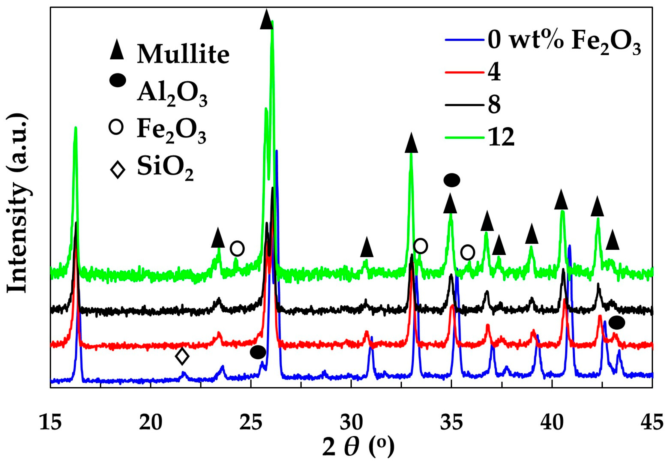
The XRD patterns of samples sintered at 1300 °C are given in Figure 2. It was shown that mullite is the main crystalline phase in all samples. It has an orthorhombic structure, consisting of octahedral chains of AlO6 interconnected by tetrahedral chains of aluminum-oxygen and/or silicon-oxygen (AlO4/SiO4). It is important to note the presence of small amounts of SiO2 (cristobalite) and Al2O3 (corundum) in the sample without Fe2O3, which indicates that amorphous SiO2 first crystallizes as quartz, then undergoes phase transformation into cristobalite, which subsequently reacts with Al2O3 to form mullite. The absence of SiO2 in samples containing Fe2O3 reveals that the reaction between SiO2 and Al2O3 and therefore mullite formation, might be accelerated by the Fe2O3 presence. The analysis of the XRD pattern of the sample containing 12 wt.% Fe2O3 shows the presence of hematite (Fe2O3), indicating that the solubility of Fe2O3 in mullite is between 8 wt.% and 12 wt.%.
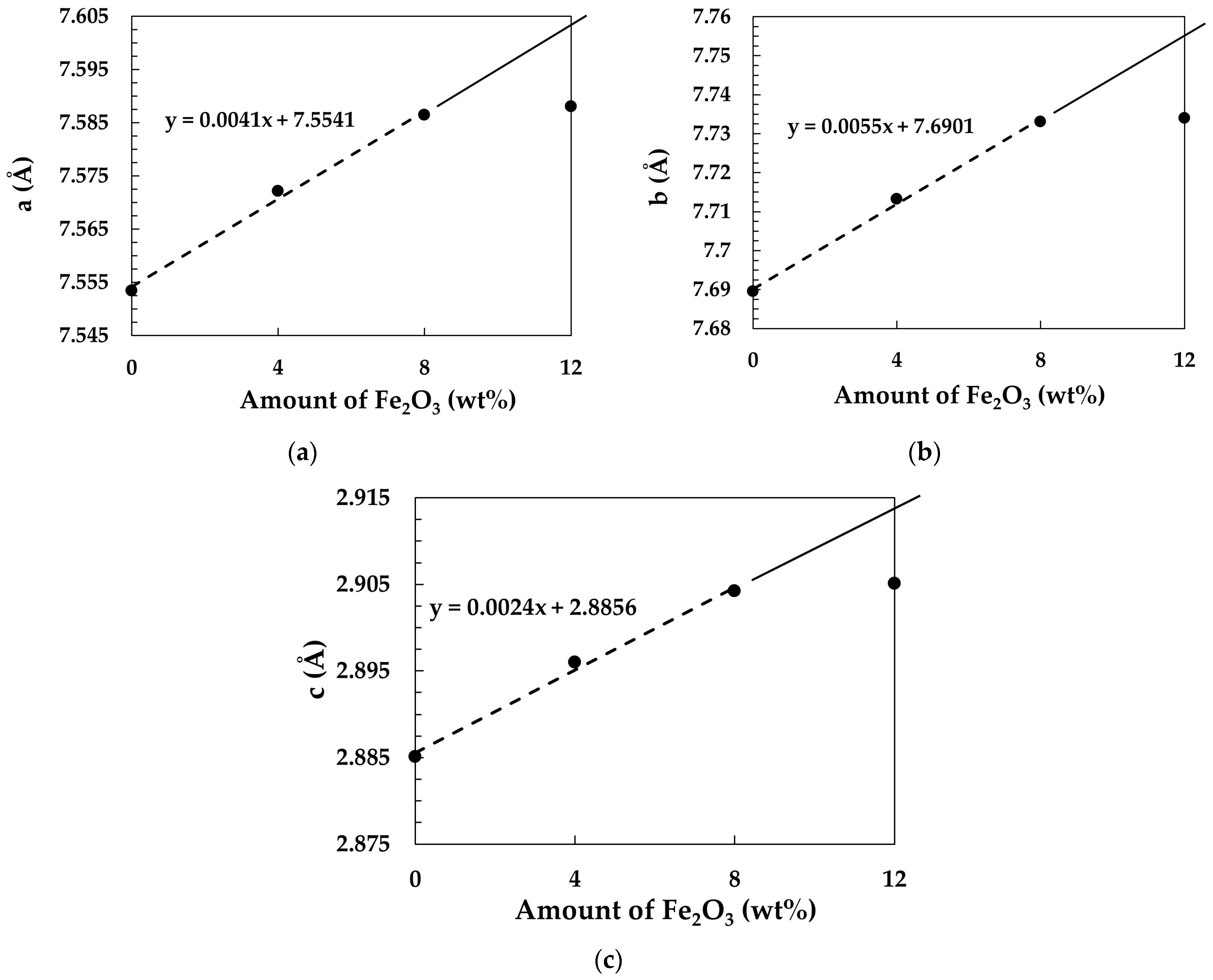
The comprehensive study on iron solubility in mullite solid solution conducted by Ye et al. confirmed that most iron ions in the mullite are in the form of Fe3+ due to a smaller atomic radius than that of Fe2+ [21]. The effective ionic radius of Fe2+ (six-fold coordination) is 0.061 nm, notably larger than that of Al3+ (six-fold coordination, 0.0535 nm), which introduces significant internal strain [22]. In contrast, the ionic radius of Fe3+ (six-fold coordination) is 0.055 nm, closely matching that of Al3+. This similarity enables Fe3+ ions to partially substitute for Al3+ ions within the mullite [AlO6] octahedra. The formation of a solid solution of Fe2O3 within the mullite structure, involving the substitution of Al3+ by Fe3+, leads to an expansion of the mullite lattice. This is evidenced by a shift in the characteristic mullite XRD peaks toward lower angles, corresponding to increased interplanar spacings (larger d-values). The shifting is especially pronounced at larger 2θ values. The addition of 4 and 8 wt.% Fe2O3 caused a continuous increase in the shifting of characteristic mullite peaks to the left. However, the shifting caused by the increase of Fe2O3 amount from 8 wt.% to 12 wt.% was much smaller and could be detected only at larger values of 2θ. This finding indicates that the maximum solubility of Fe2O3 is slightly higher than 8 wt.%. This is consistent with the results obtained in a study conducted by Ye et al., reporting that iron solubility is between 6 and 9 wt.% [21]. Zhan et al. [23] have also found that critical Fe2O3 doping threshold is 10 wt.%. The unit-cell parameters of the orthorhombic structure of mullite containing different amounts of Fe2O3 are listed in Table 1. The unit-cell parameters increase with increasing Fe2O3 content as the larger Fe3+ ions substitute for Al3+ ions.
The parameters given in Table 1 were plotted against Fe2O3 content to assess their linear relationship. As shown in Figure 3, the relationship between Fe2O3 content and unit-cell parameters is nearly linear for samples containing 0–8 wt.% Fe2O3. However, the unit-cell parameter of the sample with 12 wt.% Fe2O3 deviates from linearity, indicating that the maximum Fe ion solubility has been reached in this sample, leaving no scope for further increase in the unit-cell dimensions.
Since Fe2O3 was found to accelerate the mullite formation, a set of samples was sintered at 1200 °C in order to further examine the effect of Fe2O3 on mullite formation and grain morphology. The temperature lower than the sintering temperature was convenient due to a lower degree of reaction between SiO2 and Al2O3. These samples are not considered significant from the standpoint of mechanical properties, as they do not comprise pure mullite. The XRD patterns of samples containing a different amount of Fe2O3 sintered at 1200 °C are given in Figure 4. As observed, the sample without Fe2O3 contains a large amount of SiO2 and Al2O3. The amount continuously decreases with the increase of Fe2O3 content, whereas the amount of mullite increases. This result clearly demonstrates the capability of Fe2O3 to promote mullite formation.
The phase composition of samples sintered at 1200 °C was determined using the RIR (Reference Intensity Ratio) method within PDXL2 (version 2.0.3.0) software. Only three crystalline phases; SiO2, Al2O3 and mullite were selected in order to study the change in their content during mullite formation in sample containing different amount of Fe2O3. The results are given in Figure 5, showing the continuous decrease of SiO2 and Al2O3 content and increase in mullite content with the amount of Fe2O3, which confirms the ability of Fe2O3 to accelerate the mullite formation. The phase composition of samples sintered at 1200 °C with a particular emphasis on the presence of Al2(MoO4)3 will be discussed in detail following SEM analysis, which will be focused on the effect of Fe2O3 on microstructural development at 1200 °C.
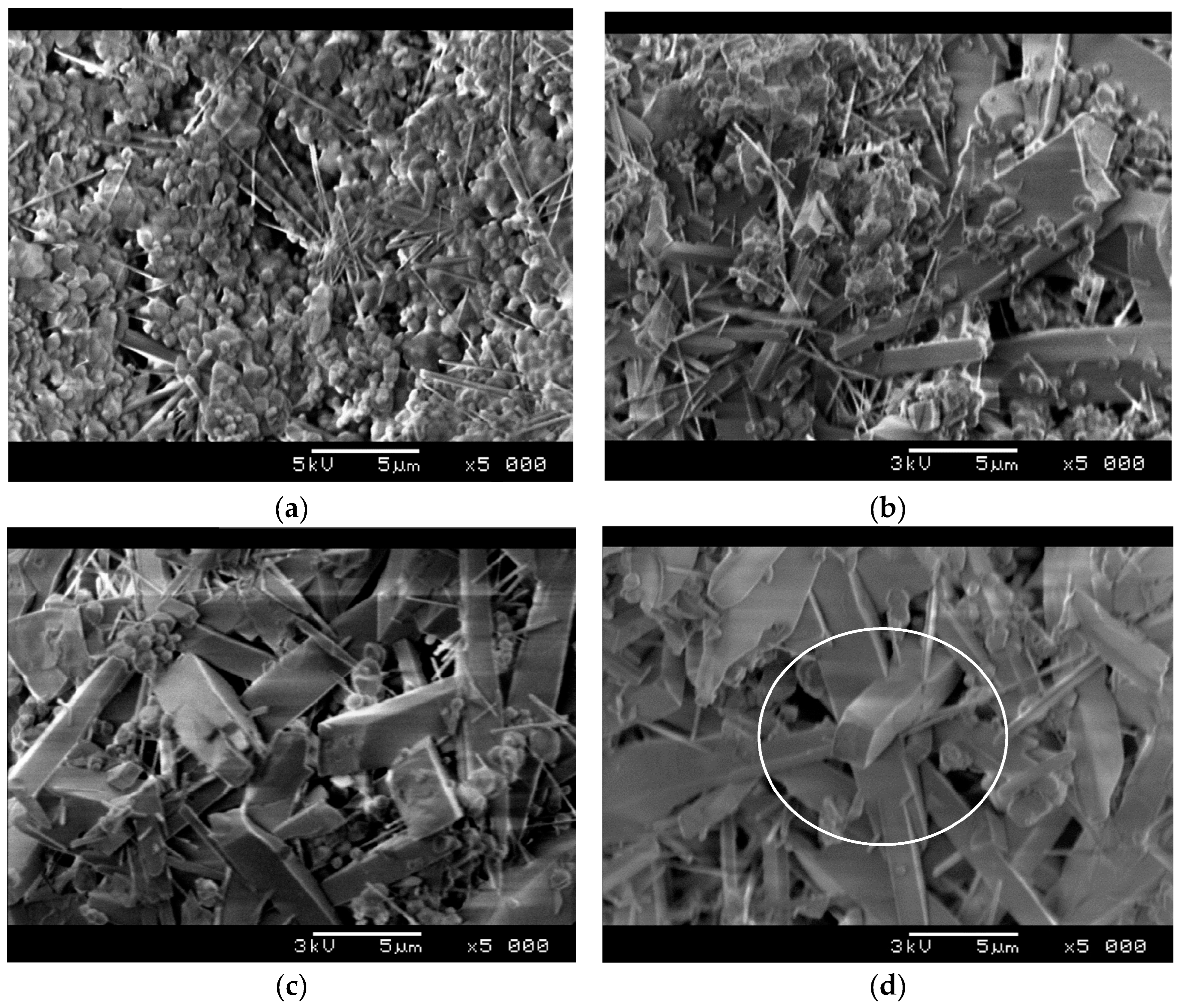
The effect of Fe2O3 on the microstructure of samples sintered at 1200 °C is presented in Figure 6. Figure 6a shows that the formation of prismatic mullite grains is preceded by the formation of mullite whiskers from the equiaxed particles of starting powder. As the figure evidences, a bunch of mullite whiskers start to grow at one point, and after that, they spread out. The above made conclusion that the presence of Fe2O3 promotes mullite formation is also confirmed by Figure 6b,c. Figure 6b shows the microstructure of a sample having 4 wt.% of Fe2O3. The comparison of the microstructure of the sample without Fe2O3 (Figure 6a) and the microstructure of the sample containing 4 wt.% Fe2O3 shows that the elongated mullite grains are much larger in the sample with 4 wt.% Fe2O3. To be more precise, the tine mullite whiskers grew into prismatic, rectangular grains. At the same time the amount of starting, equiaxed particles decreased due to the reaction between SiO2 and Al2O3. This effect is even more pronounced in samples containing 8 wt.% Fe2O3 (Figure 6c) and 12 wt.% Fe2O3 (Figure 6d). As Figure 6d shows, the microstructure of sample containing 12 wt.% Fe2O3 predominantly consists of mullite grains with small amount of unreacted starting powder located between them. It would be of great importance to point out the interlocking of acicular mullite grains that is denoted in Figure 6d. The strong bonding between interlocked grains provides a skeleton for a rigid structure that possesses high compressive strength and high porosity at the same time. This kind of microstructure normally causes a relatively small pressure drop when it comes to gas filtration, as the gas can flow along the elongated grains.
It is evident from Figure 6 that the presence of Fe2O3 accelerates mullite formation and promotes the grain growth in an elongated fashion, which is related to its crystal structure. Mullite has an orthorhombic structure, consisting of octahedral chains of AlO6 located at the vertices and in the center of the unit cell, with edges aligned in parallel along the “c” crystallographic axis. The AlO6 chains are interconnected by double tetrahedral chains of aluminum–oxygen and/or silicon–oxygen (AlO4/SiO4), also aligned in parallel with the c axis [24,25,26]. Ye et al. [20] made a calculation which showed that the presence of Fe2O3 causes a decrease in surface energy of the (001) mullite plane, which subsequently causes an increase in the growth tendency on the (001) plane and therefore preferential growth along the c-axis. A similar effect was observed in boron-dopped mullite [27]. The addition of ~6 wt.% of B2O3 caused a considerable increase in the aspect ratio of mullite grains as well as the reduction in mullite formation temperature. It was found that the presence of boron reduces the viscosity of the SiO2 containing amorphous phase and enhances atomic diffusion facilitating mullite nucleation and anisotropic grain growth. Similarly to boron, it was documented that iron also participates in the formation of the liquid phase, which promotes mullite formation. To be more precise, the presence of iron triggers the formation of an iron–silicate liquid phase which subsequently reacts with Al2O3 to form mullite. As previously mentioned, the presence of a liquid phase enhances diffusion, thereby facilitating nucleation of mullite grains, which is essential for reducing the mullite formation temperature and promoting the growth of elongated grains.
It can be concluded that the literature data ascribes the elongation of mullite grains and lowering of mullite formation temperature to the presence of dopants, i.e., iron. While this study confirms that iron can lower the temperature required for mullite formation, it does not verify iron’s critical role in the development of elongated mullite grains. Figure 7. shows samples with different amounts of Fe2O3 sintered at 1300 °C. The images were taken at two different magnifications in order to provide a comprehensive insight into the grain size and morphology.
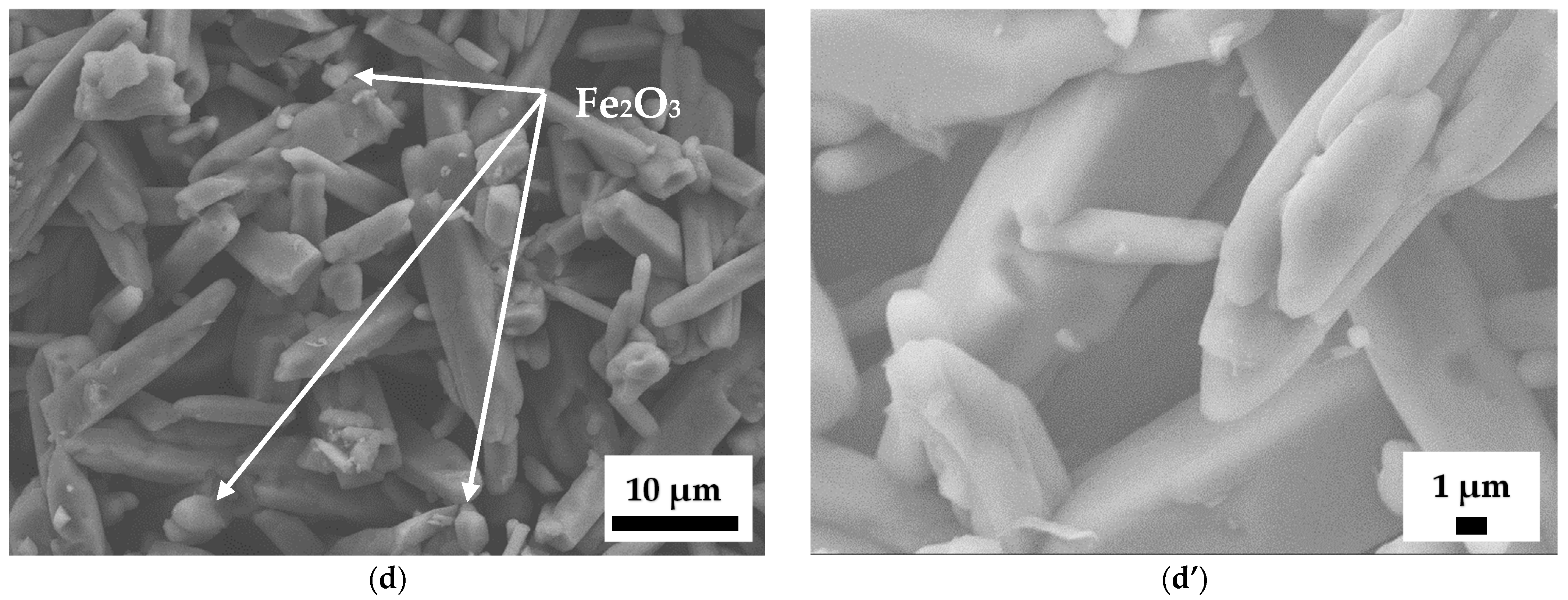
As illustrated in Figure 7a,a’, the sample without Fe2O3 contains elongated prism-like mullite grains, which means that the growth of acicular mullite grains was initiated without the presence of iron. The morphology of mullite grains in the sample with 12 wt.% Fe2O3 sintered at 1200 °C (Figure 6d) was quite similar to that of the sample without Fe2O3 sintered at 1300 °C. It would be important to point out the sharp edges of rectangular mullite prisms. As shown in Figure 7b,b’, these edges stay sharp in the sample containing 4 wt.% Fe2O3 sintered at 1300 °C. However, the edges become rounded in samples containing 8 wt.% (Figure 7c,c’) and 12 wt.% Fe2O3 (Figure 7d,d’) indicating that dissolved iron accelerates diffusion and therefore material transport. The FeO–SiO2–Al2O3 phase diagram [28] shows that the reaction between Fe ion and SiO2 can produce a liquid phase at temperatures as low as 1185 °C. The liquid phase then reacts with Al2O3 to form an iron-containing solid solution, which aligns well with the earlier conclusion that the presence of iron promotes mullite formation at 1200 °C (Figure 6). As shown in Figure 2, iron ions dissolve into the mullite structure, suggesting that their concentration in the liquid phase decreases during sintering as well as mullite grain growth. Consequently, it can be inferred that the edge rounding observed in samples with 8 and 12 wt.% Fe2O3 is primarily the result of rapid solid-state diffusion occurring at 1300 °C, facilitated by the significant amount of iron ions dissolved in mullite grains. A similar conclusion was reached by Tu et al., [29] who observed that substituting Al3+ with Gd3+ in MgAl2O4 markedly enhanced mass transport, resulting in an almost fully densified material.
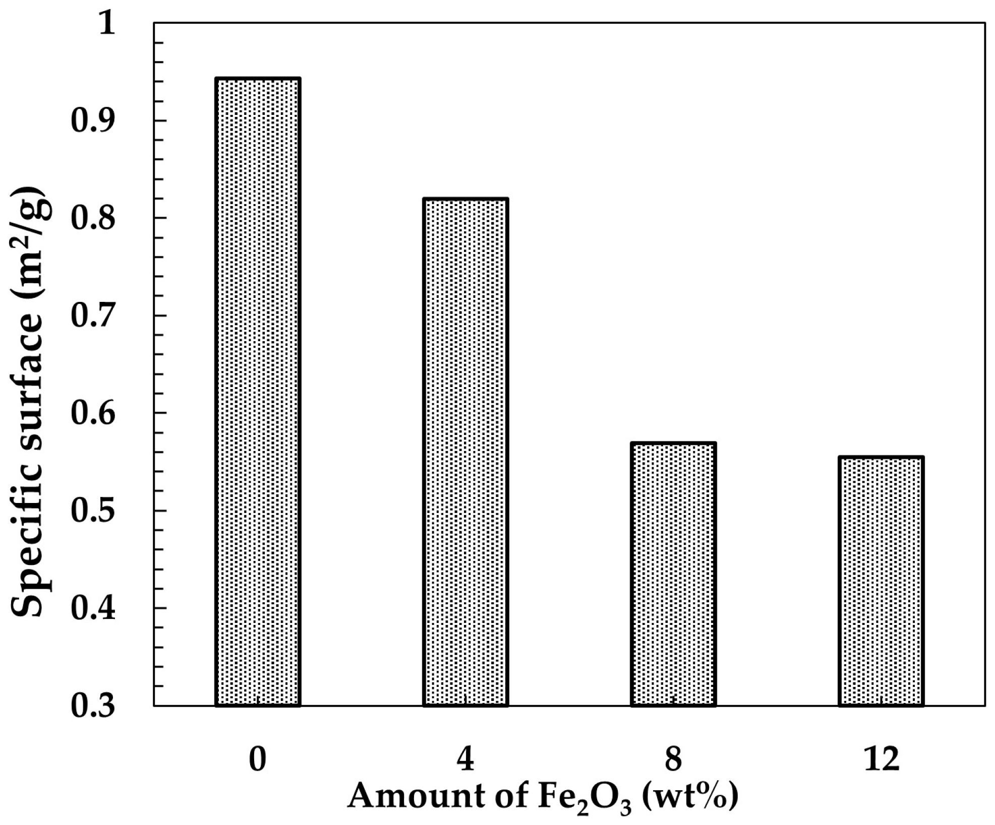
As a consequence, the grain edges become rounded as a result of material’s tendency to reduce its specific surface. This is confirmed by specific surface analysis results presented in Figure 8 showing that the specific surface continuously decreases from 0.95 m2/g in the sample without Fe2O3 to 0.55 m2/g in the sample containing 12 wt.% Fe2O3. As revealed in Figure 7d,d’, the grains in the sample containing 12 wt.% Fe2O3 predominantly exhibit rounded edges, making it difficult to identify grains with a rectangular cross-section. In addition, the Fe2O3 phase present in the samples containing 12 wt.% Fe2O3 was in the form of equiaxed grains embedded between elongated mullite grains, as marked in Figure 7d. Now the question arises: what causes the acicular grain growth? According to our previous research on mullite without an additive [11], the key component for acicular grain growth is MoO3 which reacts with Al2O3 above 500 °C to form Al2(MoO4)3 according to the following reaction [30]:
Al 2 O 3   +   3 MoO 3   500   ° C   Al 2 MoO 4 3
The newly created Al2(MoO4)3 is unstable above 800 °C and therefore it decomposed into Al2O3 and MoO3 during heating. The positive outcome of this transformation is grain refinement, which yields very fine, highly reactive MoO3 and Al2O3 particles. The melting point of MoO3 is 795 °C; however, it exhibits volatile behavior near the melting point, which was confirmed by thermogravimetric analysis conducted in our previous study [11]. A considerable weight loss due to MoO3 evaporation was measured in the temperature range from 800 to 900 °C. It was estimated that about 65 wt.% of the total amount of MoO3 evaporated during heating to 900 °C. The residual liquid MoO3 kept evaporating in the temperature interval from 900 °C to 1350 °C which was the highest temperature of thermogravimetric analysis. It is important to note that the evaporation rate significantly decreased at temperatures above 900 °C, suggesting that molten MoO3 forms a liquid mixture in which its partial pressure is reduced. The XRD analysis results, shown in Figure 4, confirm the presence of Al2(MoO4)3 in the samples sintered at 1200 °C. The characteristic peaks are located between 22 and 24°. Further increase in temperature to 1300 °C led to complete decomposition of Al2(MoO4)3. As Figure 2 evidences characteristic peaks of Al2(MoO4)3 phase were not detected in samples sintered at 1300 °C. It is believed that the presence of MoO3 favors the formation of silica-rich glassy phase, which promotes dissolution of Al2O3 and accelerates mullitization reaction [31]. EDS analysis of mullite grains in samples sintered at 1300 °C did not detect the presence of Mo, suggesting that Mo ions are not incorporated into the mullite lattice. The substitution of Al3+ by Mo6+ is unlikely due to differences in their charges and ionic radii [22]. The ionic radius of Mo6+ in six-fold coordination is 0.059 nm, which is larger than that of both Al3+ (0.0535 nm) and Fe3+ (0.055 nm). For this reason, the sintering process in samples without Fe2O3 is not as fast as that in samples containing Fe ions dissolved into the mullite lattice. Consequently, the sharp edges of elongated prismatic grains in samples without Fe2O3 are preserved even at temperatures as high as 1300 °C.
The total amount of MoO3 in the starting mixture was 23 wt.%. After intensive evaporation at temperatures between 800 and 900 °C, the residual amount of MoO3 was estimated at 8 wt.%. This is very close to the 7 wt.% identified by Chen et al. [30] as the optimal concentration for the longitudinal growth of mullite whiskers. The presence of MoO3 lowered the melting temperature of silica-rich glassy liquid and decreased the high-temperature viscosity of the liquid system which resulted in a decrease in activation energy for mullite whisker growth. To be more precise, the activation energy of longitudinal grain growth was reduced, suggesting a stronger catalytic effect on longitudinal than transverse grain growth.
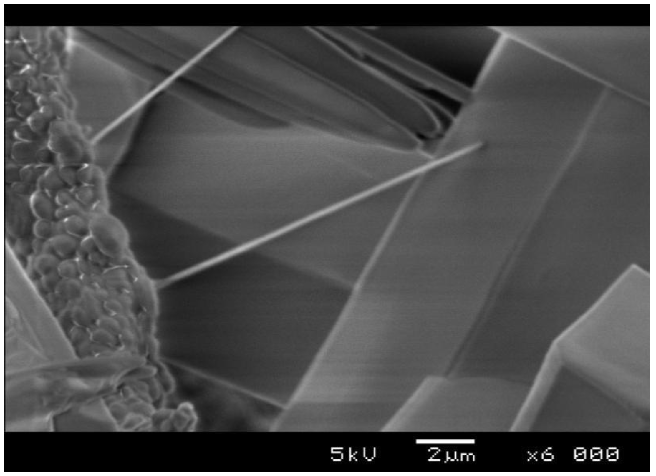
As mentioned, the source of SiO2 in this study was pulverized and calcined MoSi2, which consisted of amorphous SiO2 and MoO3. The starting mixture contained 23 wt.% of MoO3 in order to ensure the correct stoichiometric ratio of components for mullite formation. This is a relatively large amount when compared to other studies investigating the effect of MoO3 presence [30]. The advantage of a large amount of MoO3 is the empty space in samples that is formed in the temperature range 800–900 °C due to MoO3 evaporation. Since evaporation takes place prior to mullite formation, the resulting empty space allows for the unconstrained growth of elongated mullite grains. Figure 9 illustrates the formation of a mullite whisker, which is expected to develop further into a rectangular prism-like grain. It is evident that the length of the whisker is limited by the space available for its growth. The growth of the whisker is ultimately obstructed by the neighboring grains, suggesting that large pores in the green samples contribute to the high aspect ratio of mullite grains.
Figure 10 presents the effect of Fe2O3 amount on open porosity and compressive strength. The decrease in porosity is expected, knowing that iron dissolved in the mullite lattice enhances mass transport and therefore accelerates the sintering/densification process. It is important to note that the reduction in porosity is relatively minor from a filtration performance perspective. The addition of 12 wt.% of Fe2O3 caused a decrease in open porosity of only 3.6%, from 55.4% in pure mullite to 51.8% in the sample containing 12 wt.% Fe2O3. Despite the large amount of additives, the porosity of the sample containing 12 wt.% of Fe2O3, reaching a value of ~52%, is considered sufficiently high for filtering of diesel engine exhaust gases.
Unlike the relatively small change in porosity, the change in compressive strength was substantial. As shown in Figure 10, increasing the Fe2O3 content corresponded with a rise in strength, reaching 76 MPa in the sample containing 12 wt.% Fe2O3. This value was three times as high as that of mullite without Fe2O3. The improved compressive strength of samples containing Fe2O3 could be ascribed to the accelerated mass transport, which promotes sintering and therefore reinforces the contact between elongated mullite grains. As revealed in Figure 11, the two mullite grains in the sample containing 12 wt.% Fe2O3 are strongly bonded at the contact point, which reinforces the mullite skeleton and enhances its resistance to deformation under compression. However, this type of reinforcement does not significantly impact porosity because of the initially high porosity of the samples and the substantial gaps between grains formed during MoO3 evaporation before sintering and densification.
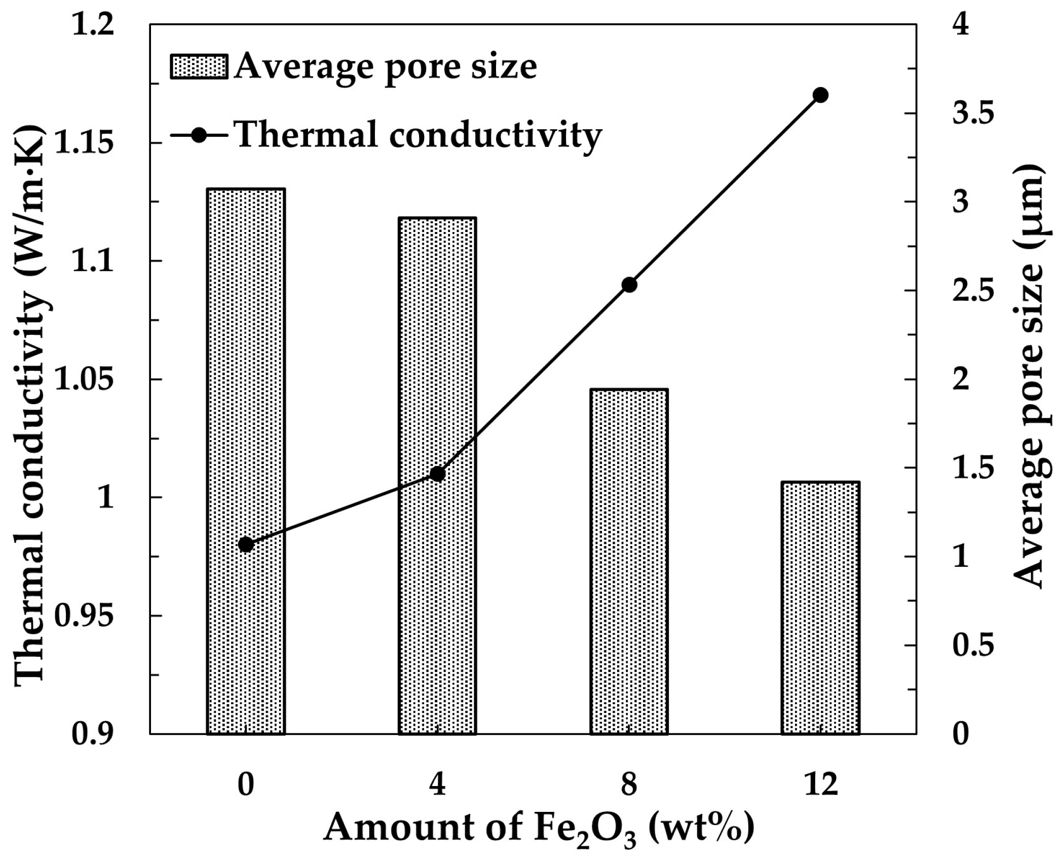
Another important characteristic of material for diesel engine exhaust filtration is thermal conductivity [32,33]. Since the captured soot will eventually clog the filter, it is essential to periodically burn off the accumulated soot. The soot burnout generates local overheating which commonly causes filter cracking due to thermal shock [34]. Therefore, it is important to design a porous filter material with adequate thermal conductivity (>0.5 W/m·K) to ensure more uniform heat distribution. As presented in Figure 11, the addition of 4 wt.% Fe2O3 does not change the thermal conductivity. It is the same as the conductivity of the sample without Fe2O3. The porosity (Figure 10), phase composition (Figure 2) and microstructure (Figure 7) of the samples with 0 wt.% and 4 wt.% Fe2O3 are very similar, as is the thermal conductivity. The increase in thermal conductivity was recorded for samples containing 8 and 12 wt.% Fe2O3. The coalescence of mullite grains in these samples provides paths for heat transfer, causing an increase in conductivity [35]. In addition, the thermal conductivity of Fe2O3 at 300 °C is about 6 W/m·K, which is higher than that of mullite. Therefore, the presence of Fe2O3 secondary phase in samples containing 12 wt.% Fe2O3 is likely responsible for the high thermal conductivity of these samples. The thermal conductivity is inversely proportional to the pore size. As shown in Figure 12, the average pore sizes in samples containing 0 wt.% and 4 wt.% Fe2O3 are nearly identical, which aligns well with the observation that their thermal conductivities are also similar. The increase in Fe2O3 content led to a reduction in pore size, which, as expected, resulted in an increase in thermal conductivity of samples containing 8 and 12 wt.% Fe2O3. Considering that diesel particulate sizes range from 10 to 200 nm, it is likely that the significant reduction in pore size observed in samples containing 12 wt.% Fe2O3 could increase the risk of particulate clogging [36].

4. Conclusions

Porous acicular mullite was fabricated at 1300 °C starting from Al2O3 and a mixture of SiO2 and MoO3 obtained by previous oxidation of waste MoSi2. The addition of Fe2O3 was an effective way to improve the compressive strength of acicular mullite with minimal decrease in porosity, primarily through densification and improved microstructural characteristics. The presence of 12 wt.% Fe2O3 improved compressive strength from ~25 MPa (pure mullite) to ~76 MPa, whereas the porosity decreased from 55.4% (pure mullite) to 51.8%. It was found that the presence of Fe2O3 reduces the mullite formation temperature, which was ascribed to the formation of a liquid phase and accelerated diffusion. The solubility limit of iron oxide in mullite was between 8 and 12 wt.%. This study demonstrated that the presence of Fe2O3 was not a prerequisite for the formation of mullite acicular (prismatic) grains. It was shown that the presence of MoO3 also initiates the formation of elongated mullite grains. Although mullite formation with MoO3 alone (without Fe2O3) occurs at a slightly higher temperature, the grains maintain their rectangular shape even at temperatures as high as 1300 °C, resulting in a higher specific surface area compared to samples containing Fe2O3. The presence of iron ions, along with enhanced mass transport, promoted the rounding of sharp edges in prismatic mullite grains. This led to a reduction in specific surface area to 0.55 m2/g in the sample with 12 wt.% Fe2O3, which is significantly lower than the 0.94 m2/g observed in pure mullite. Enhanced diffusion also contributed to the increased thermal conductivity, reaching a value of 1.17 W/m·K in the sample with 12 wt.% Fe2O3. The measured values of the three key properties; compressive strength, porosity, and thermal conductivity, are within the target ranges necessary for materials intended for diesel engine exhaust filtration.

Author Contributions

Conceptualization, M.O. and D.B.; methodology, M.O., D.B. and C.-A.W.; validation, M.O., C.-A.W. and D.B.; formal analysis, M.K., N.A. and C.-A.W.; investigation, M.O., M.K., N.A., C.-A.W. and D.B.; data curation, M.O.; writing—original draft preparation, M.O. and D.B.; writing—review and editing, M.O., C.-A.W. and D.B.; visualization, M.K.; supervision, C.-A.W. and D.B. All authors have read and agreed to the published version of the manuscript.

Funding

The research was supported by the Ministry of Science, Technological Development and Innovation of the Republic of Serbia (grant number: 451-03-136/2025-03/200017) and the Science Fund of the Republic of Serbia, #GRANT No 14883, “Porous Acicular Mullite Ceramics with Soot Oxidation Catalyst for Diesel Particulate Filters—PAMSOC-DPF”.

Data Availability Statement

The original contributions presented in this study are included in the article. Further inquiries can be directed to the corresponding author.

Conflicts of Interest

The authors declare no conflicts of interest.

References

  1. Schneider, H.; Schreuer, J.; Hildmann, B. Structure and Properties of Mullite—A Review. J. Eur. Ceram. Soc. 2008, 28, 329–344. [Google Scholar] [CrossRef]
  2. Hammel, E.C.; Ighodaro, O.L.R.; Okoli, O.I. Processing and Properties of Advanced Porous Ceramics: An Application Based Review. Ceram. Int. 2014, 40, 15351–15370. [Google Scholar] [CrossRef]
  3. Hsiung, C.H.H.; Pyzik, A.J.; De Carlo, F.; Xiao, X.; Stock, S.R.; Faber, K.T. Microstructure and Mechanical Properties of Acicular Mullite. J. Eur. Ceram. Soc. 2013, 33, 503–513. [Google Scholar] [CrossRef]
  4. Hou, Z.; Cui, B.; Liu, L.; Liu, Q. Effect of the Different Additives on the Fabrication of Porous Kaolin-Based Mullite Ceramics. Ceram. Int. 2016, 42, 17254–17258. [Google Scholar] [CrossRef]
  5. Swanson, J.; Watts, W.; Kittelson, D.; Newman, R.; Ziebarth, R. Filtration Efficiency and Pressure Drop of Miniature Diesel Particulate Filters. Aerosol Sci. Technol. 2013, 47, 452–461. [Google Scholar] [CrossRef]
  6. Luo, M.H.; Zhou, J.E.; Wang, Y.Q.; Wang, D.L.; Wang, S.L. Preparation and Characterization of Porous Acicular Mullite Ceramics. Adv. Mater. Res. 2011, 412, 65–68. [Google Scholar] [CrossRef]
  7. Hashimoto, S.; Yamaguchi, A. Synthesis of Needlelike Leucite Crystals Using Potassium Sulfate Flux. J. Ceram. Soc. Jpn. 2000, 108, 710–713. [Google Scholar] [CrossRef]
  8. Hashimoto, S.; Yamaguchi, A. Synthesis of Needlelike Mullite Particles Using Potassium Sulfate Flux. J. Eur. Ceram. Soc. 2000, 20, 397–402. [Google Scholar] [CrossRef]
  9. Choi, H.; Lee, J. Synthesis of Mullite Whiskers. J. Am. Ceram. Soc. 2002, 85, 481–483. [Google Scholar] [CrossRef]
  10. Pyzik, A.J.; Todd, C.S.; Han, C. Formation Mechanism and Microstructure Development in Acicular Mullite Ceramics Fabricated by Controlled Decomposition of Fluorotopaz. J. Eur. Ceram. Soc. 2008, 28, 383–391. [Google Scholar] [CrossRef]
  11. Bučevac, D.; Dapčević, A.; Maksimović, V. Porous Acicular Mullite Obtained by Controlled Oxidation of Waste Molybdenum Disilicide. Mater. Res. Bull. 2014, 50, 155–160. [Google Scholar] [CrossRef]
  12. Lohfeld, S.; Schütze, M.; Böhm, A.; Güther, V.; Rix, R.; Scholl, R. Oxidation Behaviour of Particle Reinforced MoSi2; Composites at Temperatures up to 1700 °C. Mater. Corros. 2005, 56, 250–258. [Google Scholar] [CrossRef]
  13. Jalaluddin, M.L.; Azlan, U.A.-A.; Rashid, M.W.A.; Tamin, N.; Masri, M.N. A Review of Pore-Forming Agents on the Structures, Porosities, and Mechanical Properties of Porous Ceramics. AIMS Mater. Sci. 2024, 11, 634–665. [Google Scholar] [CrossRef]
  14. Xu, G.; Ma, Y.; Cui, H.; Ruan, G.; Zhang, Z.; Zhao, H. Preparation of Porous Mullite–Corundum Ceramics with Controlled Pore Size Using Bioactive Yeast as Pore-Forming Agent. Mater. Lett. 2014, 116, 349–352. [Google Scholar] [CrossRef]
  15. Yang, Y.; Hu, Z.; Chang, Q.; Liu, H.; Yang, K.; Wang, Y. Effect of Type and Content of Pore-Forming Agents on Properties of Porous Alumina Membrane Support. IOP Conf. Ser. Mater. Sci. Eng. 2018, 452, 022047. [Google Scholar] [CrossRef]
  16. Kong, L.B.; Huang, H.; Zhang, T.S.; Gan, Y.B.; Ma, J.; Boey, F.; Zhang, R.F. Effect of Transition Metal Oxides on Mullite Whisker Formation from Mechanochemically Activated Powders. Mater. Sci. Eng. A 2003, 359, 75–81. [Google Scholar] [CrossRef]
  17. Ilić, S.; Ivanovski, V.N.; Radovanović, Ž.; Egelja, A.; Kokunešoski, M.; Šaponjić, A.; Matović, B. Structural, Microstructural and Mechanical Properties of Sintered Iron-Doped Mullite. Mater. Sci. Eng. B 2020, 256, 114543. [Google Scholar] [CrossRef]
  18. Schneider, H.; Rager, H. Iron Incorporation in Mullite. Ceram. Int. 1986, 12, 117–125. [Google Scholar] [CrossRef]
  19. Brownell, W.E. Subsolidus Relations Between Mullite and Iron Oxide. J. Am. Ceram. Soc. 1958, 41, 226–230. [Google Scholar] [CrossRef]
  20. Ye, H.; Li, Y.; Sun, J. Kinetic Study on the Anisotropic Grain Growth of Elongated Iron-Containing Mullite. Ceram. Int. 2019, 45, 12934–12941. [Google Scholar] [CrossRef]
  21. Ye, H.; Li, Y.; Sun, J.; Sun, Y.; Wu, X.; Yan, M. Novel Iron-Rich Mullite Solid Solution Synthesis Using Fused-Silica and α-Al2O3 Powders. Ceram. Int. 2019, 45, 4680–4684. [Google Scholar] [CrossRef]
  22. Shannon, R.D. Revised Effective Ionic Radii and Systematic Studies of Interatomic Distances in Halides and Chalcogenides. Acta Crystallogr. Sect. A 1976, 32, 751–767. [Google Scholar] [CrossRef]
  23. Zhan, H.; Wang, H.; Li, Y.; Li, S.; Cai, Z.; Qiao, Z. Iron Element Behavior and Microstructure Evolution of Mullite–Corundum Ceramics in High-Temperature CO Atmosphere. J. Am. Ceram. Soc. 2025, 108, e70027. [Google Scholar] [CrossRef]
  24. Schneider, H.; Fischer, R.X.; Schreuer, J. Mullite: Crystal Structure and Related Properties. J. Am. Ceram. Soc. 2015, 98, 2948–2967. [Google Scholar] [CrossRef]
  25. Romero, M.; Padilla, I.; Contreras, M.; López-Delgado, A. Mullite-Based Ceramics from Mining Waste: A Review. Minerals 2021, 11, 332. [Google Scholar] [CrossRef]
  26. Lima, L.K.S.; Silva, K.R.; Menezes, R.R.; Santana, L.N.L.; Lira, H.L. Microstructural Characteristics, Properties, Synthesis and Applications of Mullite: A Review. Ceramica 2022, 68, 126–142. [Google Scholar] [CrossRef]
  27. Zhang, G.; Fu, Z.; Wang, Y.; Wang, H.; Wang, W.; Zhang, J.; Lee, S.W.; Niihara, K. Boron-Doped Mullite Derived from Single-Phase Gels. J. Eur. Ceram. Soc. 2010, 30, 2435–2441. [Google Scholar] [CrossRef]
  28. Muan, A. Phase Equilibria at Liquidus Temperatures in the System Iron Oxide–Al2O3–SiO2 in Air Atmosphere. J. Am. Ceram. Soc. 1957, 40, 121–133. [Google Scholar] [CrossRef]
  29. Tu, G.; Wang, H.; Tu, B.; Xu, P.; Ren, L.; Huang, Q.; Yang, R.; Wang, W.; Fu, Z. Achieving Near-Theoretical Transmittance in MgAl2O4 Ceramic at Reduced Sintering Temperature via Solution Substitution. J. Eur. Ceram. Soc. 2025, 45, 117382. [Google Scholar] [CrossRef]
  30. Chen, W.; Gu, X.; Fan, A.; Li, H.; Su, Q. In-Situ Low-Temperature Synthesis of Mullite Whiskers from MoO3-Doped Industrial Silica-Alumina Waste and Growth Kinetics Study. Ceram. Int. 2025, 51, 39498–39510. [Google Scholar] [CrossRef]
  31. Zhu, L.; Dong, Y.; Hampshire, S.; Cerneaux, S.; Winnubst, L. Waste-to-Resource Preparation of a Porous Ceramic Membrane Support Featuring Elongated Mullite Whiskers with Enhanced Porosity and Permeance. J. Eur. Ceram. Soc. 2015, 35, 711–721. [Google Scholar] [CrossRef]
  32. Benaqqa, C.; Gomina, M.; Beurotte, A.; Boussuge, M.; Delattre, B.; Pajot, K.; Pawlak, E.; Rodrigues, F. Morphology, Physical, Thermal and Mechanical Properties of the Constitutive Materials of Diesel Particulate Filters. Appl. Therm. Eng. 2014, 62, 599–606. [Google Scholar] [CrossRef]
  33. Dong, R.; Zhang, Z.; Ye, Y.; Huang, H.; Cao, C. Review of Particle Filters for Internal Combustion Engines. Processes 2022, 10, 993. [Google Scholar] [CrossRef]
  34. Zhang, Z.; Dong, R.; Lan, G.; Yuan, T.; Tan, D. Diesel Particulate Filter Regeneration Mechanism of Modern Automobile Engines and Methods of Reducing PM Emissions: A Review. Environ. Sci. Pollut. Res. 2023, 30, 39338–39376. [Google Scholar] [CrossRef] [PubMed]
  35. Takeda, M.; Onishi, T.; Nakakubo, S.; Fujimoto, S. Physical Properties of Iron-Oxide Scales on Si-Containing Steels at High Temperature. Mater. Trans. 2009, 50, 2242–2246. [Google Scholar] [CrossRef]
  36. Fino, D. Diesel Emission Control: Catalytic Filters for Particulate Removal. Sci. Technol. Adv. Mater. 2007, 8, 93–100. [Google Scholar] [CrossRef]
Figure 1. XRD pattern of the starting composition containing 12 wt.% Fe2O3 (hematite).
Ceramics 08 00111 g001
Figure 2. XRD pattern of samples containing different amounts of Fe2O3 sintered at 1300 °C for 4 h.
Ceramics 08 00111 g002
Figure 3. Effect of Fe2O3 amount on unit-cell parameters of mullite samples sintered at 1300 °C for 4 h; (a) unit-cell parameter a, (b) unit-cell parameter b, and (c) unit-cell parameter c.
Ceramics 08 00111 g003
Figure 4. XRD pattern of samples containing different amount of Fe2O3 sintered at 1200 °C for 4 h.
Ceramics 08 00111 g004
Figure 5. Effect of Fe2O3 amount on phase composition of samples sintered at 1200 °C for 4 h.
Ceramics 08 00111 g005
Figure 6. SEM micrographs of samples sintered at 1200 °C for 4 h containing (a) 0 wt.%, (b) 4 wt.%, (c) 8 wt.% and (d) 12 wt.% Fe2O3. The white circle denotes an interlocking of mullite grains.
Ceramics 08 00111 g006
Figure 7. SEM micrographs of samples sintered at 1300 °C for 4 h containing (a,a’) 0 wt.%, (b,b’) 4 wt.%, (c,c’) 8 wt.%, and (d,d’) 12 wt.% Fe2O3 taken at two different magnifications, 2000× and 5000× (designated with ‘).
Ceramics 08 00111 g007aCeramics 08 00111 g007b
Figure 8. Specific surface area of samples containing different amount of Fe2O3 sintered at 1300 °C for 4 h.
Ceramics 08 00111 g008
Figure 9. SEM micrograph of sample containing no Fe2O3 sintered at 1300 °C for 4 h.
Ceramics 08 00111 g009
Figure 10. Effect of Fe2O3 amount on open porosity and compressive strength of samples sintered at 1300 °C for 4 h.
Ceramics 08 00111 g010
Figure 11. SEM micrograph of a sample containing 12 wt.% Fe2O3 sintered at 1300 °C for 4 h.
Ceramics 08 00111 g011
Figure 12. Thermal conductivity and average pore size of samples containing different amounts of Fe2O3 sintered at 1300 °C for 4 h.
Ceramics 08 00111 g012
Table 1. Unit-cell parameters of mullite with varying Fe2O3 content, determined from XRD patterns using Rietveld refinement in the FullProf (Version 5.60) software package. The estimated standard deviations are given in round brackets.
Fe2O3 Contenta (Å)b (Å)c (Å)
07.5534 (8)7.6895 (8)2.8851 (3)
47.5721 (9)7.7132 (9)2.8960 (4)
87.5864 (12)7.7331 (12)2.9042 (5)
127.5880 (11)7.7340 (11)2.9051 (4)
Disclaimer/Publisher’s Note: The statements, opinions and data contained in all publications are solely those of the individual author(s) and contributor(s) and not of MDPI and/or the editor(s). MDPI and/or the editor(s) disclaim responsibility for any injury to people or property resulting from any ideas, methods, instructions or products referred to in the content.