Article

Fabrication and Properties of ITTO Segments for Cylindrical Targets by Pressureless Oxygen Atmosphere Sintering Method

1
Engineering Research Center of Electronic Information Materials and Devices, Ministry of Education, Guangxi Key Laboratory of Information Materials, Guilin University of Electronic Technology, Guilin 541004, China
2
Luoyang Crystal Union Photoelectric Materials Co., Ltd., Luoyang 471100, China
*
Authors to whom correspondence should be addressed.
Ceramics 2025, 8(2), 75; https://doi.org/10.3390/ceramics8020075
Submission received: 23 April 2025 / Revised: 3 June 2025 / Accepted: 14 June 2025 / Published: 18 June 2025
(This article belongs to the Special Issue Advances in Electronic Ceramics, 2nd Edition)

Abstract

Cylindrical targets have a high utilization rate, but are difficult to manufacture. A large hollow ITTO segment with thin walls was prepared by cold isostatic pressure and two-stage sintering. The fabrication process yielded a segment with an outer diameter of 153 mm, an inner diameter of 135 mm, and a length of 700 mm, indicating a length to thickness ratio of up to 78. The dense and uniform green bodies ensure the achievement of high density and uniformity of the sintered body throughout its volume. The segment exhibited a high relative density of about 99.5% and a low resistivity of below 3.4 × 10⁻⁴ Ω·cm. The density and resistivity illustrate a minimal inhomogeneity along the length of the segment. The segment exhibits a cubic bixbyite phase and is characterized by densely packed fine grains with an average size of several microns. Therefore, these results establish a substantial foundation for the large-scale production of cylindrical ITTO segments.

1. Introduction

Sn-doped In2O3 (ITO) transparent conductive oxide (TCO) films are widely used in devices such as liquid crystal displays, organic light-emitting diodes, solar cells, touch screens, and e-paper [1,2,3,4,5]. Large-area ITO films with 10 wt% SnO2 doping content have typically been deposited on glass or flexible substrates by magnetron sputtering technology [6,7]. Therefore, suitable In2O3-based ceramic targets are crucial for the deposition of ITO films in large-area coating applications.
Planar ceramic targets have been extensively used in industrial production, and their utilization in conventional cathodes with moving magnet configurations can be increased to 40% [8]. However, low utilization is not conducive to reducing the cost of devices [9]. A notable milestone was the innovation of cylindrical (tube) targets in rotary cathodes, with their highest utilization rate reaching up to 90% [10]. Moreover, 360-degree rotation during the sputtering process contributes to inhibiting arcing, applying high power density, and depositing large-area uniform films [11,12]. Consequently, the deposition of ITO films by cylindrical targets has become a widely accepted industry standard [13].
Notwithstanding their significant advantages, cylindrical targets present several technical challenges. In the case of long cylindrical targets, such as those measuring 3 m and 4 m, multiple hollow cylindrical segments are aligned and bonded to a metal backing tube (stainless steel, Ti) [14]. The primary disadvantage associated with long cylindrical segments is their increased complexity and cost during manufacturing, a factor that is particularly salient in the context of ceramic targets [15]. The fabrication of ceramic segments is analogous to that of planar targets, and achieving high density and low resistivity is equally important to resist abnormal discharge during sputtering [16].
Nanopowders have been proposed as a means to enhance sintering activity and facilitate the preparation of green bodies. Hot isostatic pressing (HIP) and uniaxial hot pressing (UHP) can simultaneously provide high temperature and high pressure on the sintered material, which is attractive for sintering high-density oxide targets [17,18]. However, oxygen loss is their main disadvantage [19]. The uniaxial pressing of ZnO:Al powders into a tube shape and subsequent sintering resulted in a tapered product owing to the nonuniform green density. To suppress the taper, an initial heat treatment under external pressure was applied prior to the final sintering [20]. Presently, the predominant process for the fabrication of oxide targets involves the pressureless sintering of green bodies [21]. ZnO-based cylinder segments with an outer diameter of 72 mm, an inner diameter of 47 mm, and a height of 36 mm were fabricated by the spark plasma sintering method [22]. Planar ITO targets were fabricated on a large scale at approximately 1580 °C in an oxygen atmosphere [23]. The significant shrinkage that occurs during the sintering process results in a high probability of deformation of hollow, elongated, and thin-walled green bodies [24]. These negative phenomena have a significant impact on the density, resistivity, uniformity, and deformation of the resultant ITO targets. Furthermore, the dense and regular green bodies contribute to the fabrication of sintered bodies that are in close proximity to the required final dimensions, thereby minimizing subsequent machining processes. There have been several reports on the deposition of TCO films by cylindrical ITO targets [25,26,27,28]. Unfortunately, the focus on the fabrication and properties of cylindrical ITO targets has been inadequate.
In response to the demand for cylindrical targets in solar cells, a 2.5 wt% SnO2- and 0.5 wt% TiO2-doped In2O3 (ITTO) segment with a hollow, thin-walled structure was prepared by cold isostatic pressure and two-stage sintering. The phase structure, microstructure, density, resistivity, and uniformity were investigated.

2. Materials and Methods

The In2O3 (BET = 8.2 m2/g), SnO2 (BET = 7.8 m2/g), and TiO2 (BET = 15.8 m2/g) nano raw material powders were provided by Luoyang Crystal Union Photoelectric Materials Co., Ltd. (Luoyang, Henan province, China). The doping contents of SnO2 and TiO2 were 2.5 wt% and 0.5 wt%, respectively. The powders were dispersed by DI water with a solid content of 50% in a ball mill tank, and the weight ratio of the zirconia balls to the powders in the slurry was 5:1. The slurry was then subjected to a grinding process in a sand mill, operating at a speed of 1250 rpm for 6 h. Subsequently, the slurry containing 0.6% polyvinyl alcohol (PVA) was dried and granulated by means of centrifugal atomization (Ohkawara, SFOC-25, Shanghai, China). The green bodies of the cylindrical segment were fabricated by compacting granulated powders using the cold isostatic pressure technique (ChuanXi, CIP-800, Chengdu, China) and a polyurethane mold under 240 MPa. The green bodies exhibited cylindrical dimensions with an external diameter of 190 mm, an internal diameter of 162.5 mm, and a length of 749 mm. The green bodies with a relative density of about 57% were dewaxed at 600 °C for 5 h, and then sintered in an industrial production furnace (Alcera, RB-18, Suzhou, China) under an oxygen flow rate of 30 L/min. The two-stage sintering temperature was initially set at 1580 °C for 5 h, and subsequently reduced to 1550 °C for 24 h.
The phase structure was studied by X-ray diffraction (XRD, D8 Advance, Bruker, Billerica, MA, USA). Scanning electron microscopy (FE-SEM, Tecnai-450, FEI, Portland, OR, USA) was employed to observe the microstructure and the elemental distribution. Statistical analysis of the average grain size was conducted using Nano measure software (V1.2.5). The density was determined using the Archimedes method, and then the relative density was calculated by comparison with the theoretical density (7.16 g/cm3). The resistivity was measured by the four-point probe method (MCP-T700, Mitsubishi, Tokyo, Japan).

3. Results

The morphologies of the In2O3, SnO2, and TiO2 powders in Figure 1 illustrate that all the particles are nanometer-sized, and these powders are well dispersed, which contributes to even mixing of the powders. The morphology of the granulated powders in Figure 2a shows relatively round spherical particles with a smooth surface. The apparent density and tap density of the granulated powders are 1.56 g/cm3 and is 2.1 g/cm3, respectively, which contributes to pressing dense green bodies [29]. It can be seen from Figure 2b that the cross-sectional morphology of the green body has a dense microstructure, which can reduce the difficulty of sintering densification.
As illustrated in Figure 3, sampling was performed at five equidistant positions along a 700 mm-long segment to evaluate the structural and electrical property uniformity. These sampling positions were designated as a to e sequentially from right to left. The XRD patterns of the samples taken from the different positions along the ITTO targets are shown in Figure 3. It can be seen that the samples at different positions show only the diffraction peaks of the cubic bixbyite In2O3 phase, indicating that the TiO2 and SnO2 dopants fully reacted with In2O3 and formed a new solid solution [30]. The impurity phases are not visible because the total doping content was only 3 wt%. The doping content in this work is less than the solid solubility limit [31], so no second phase was generated. Therefore, the segment has a single-phase structure at different positions.
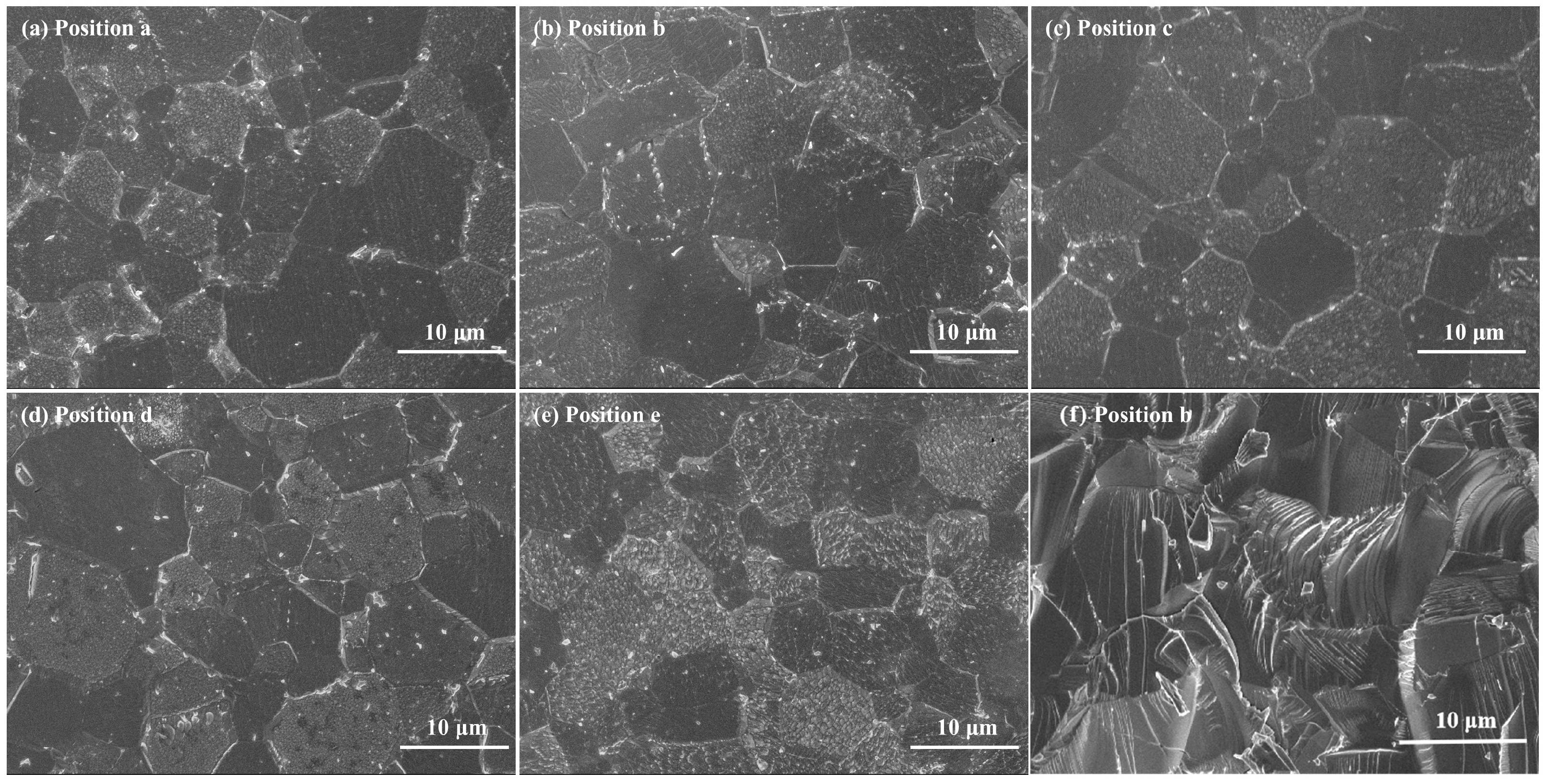
Figure 4a–e shows the polished and etched surface morphologies of the samples taken from the different positions along the ITTO segment. It can be seen that the microstructure illustrates clear grains and grain boundaries, and the grains are tightly bounded together. The cross-sectional morphologies shown in Figure 4f present the dense microstructure and transgranular fracture. As is well known, transgranular fracture indicates higher flexural strength [32], which contributes to resisting the stress generated during target bonding and plasma bombardment. As illustrated in Figure 4, the grain size of the samples at different positions is found to be relatively consistent. The grain size distribution of the samples taken from the different positions in Figure 5 shows that the segment has a wide range of grain size from 2 μm to 16 μm. The average grain size is about 5.5 μm. The difference in grain size between the two ends is related to the vertical placement of the segment during the sintering procedure. The pressure borne by the upper and lower ends of the segment is different because the segment has a high specific gravity (>7 g/cm3) and a longer length (>700 mm). For ITTO targets doped with low SnO2 content, it is difficult to control grain growth compared to 10 wt% SnO2-doped ITTO targets [32]. However, the ITTO segment still achieves fine grains and uniform grain distribution, which helps to deposit uniform thin films [33].
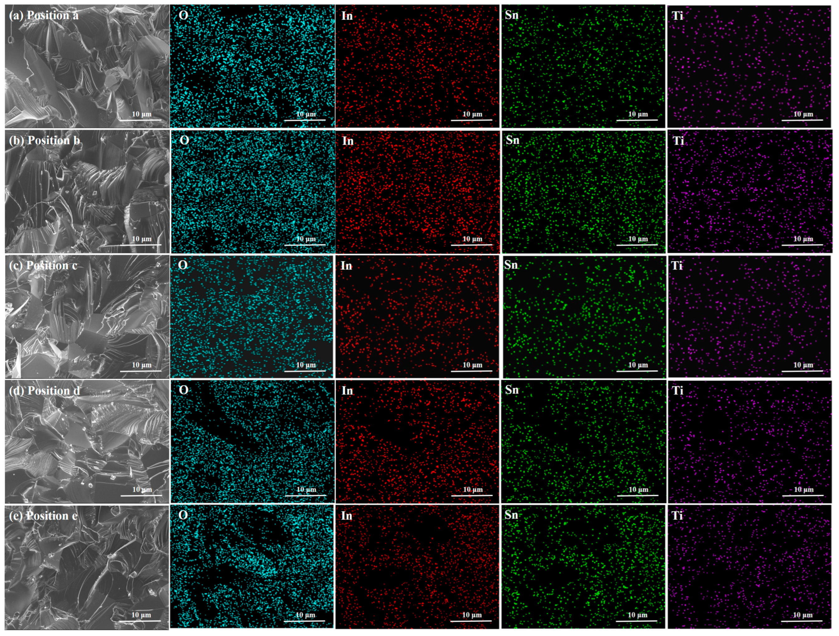
The occurrence of target poisoning is not only due to the low density of the target but also related to the distribution of doping elements. Sputtering targets with uneven element distribution are more prone to forming nodules on their surface [34]. Figure 6 shows the elemental distribution of the samples taken from the different positions along the ITTO segment. The mappings indicate that In, Sn, Ti, and O in the segment are uniformly distributed, and the unwanted segregation phenomenon of the Sn and Ti doping elements has not been observed. Therefore, the uniform element distribution at different positions is beneficial for inhibiting nodule formation during the magnetron sputtering process.
The above microstructural analysis indicates that the segment has a dense structure and fine grains, contributing to the achievement of high density and low resistivity. Figure 7 shows the relative density of the samples taken from the different positions along the ITTO segment. It can be seen that all the samples at different positions have a high relative density of about 99.5%, with the maximum density of 99.499% obtained at the middle position. The difference in density at different positions can be ignored, and the maximum difference is only 0.007%. Low SnO2 content makes it difficult to promote sintering densification of the ITO targets. Therefore, it can be concluded that the TiO2 dopants can also function as a sintering aid, thereby effectively promoting the sintering densification of closely packed ceramics [35].
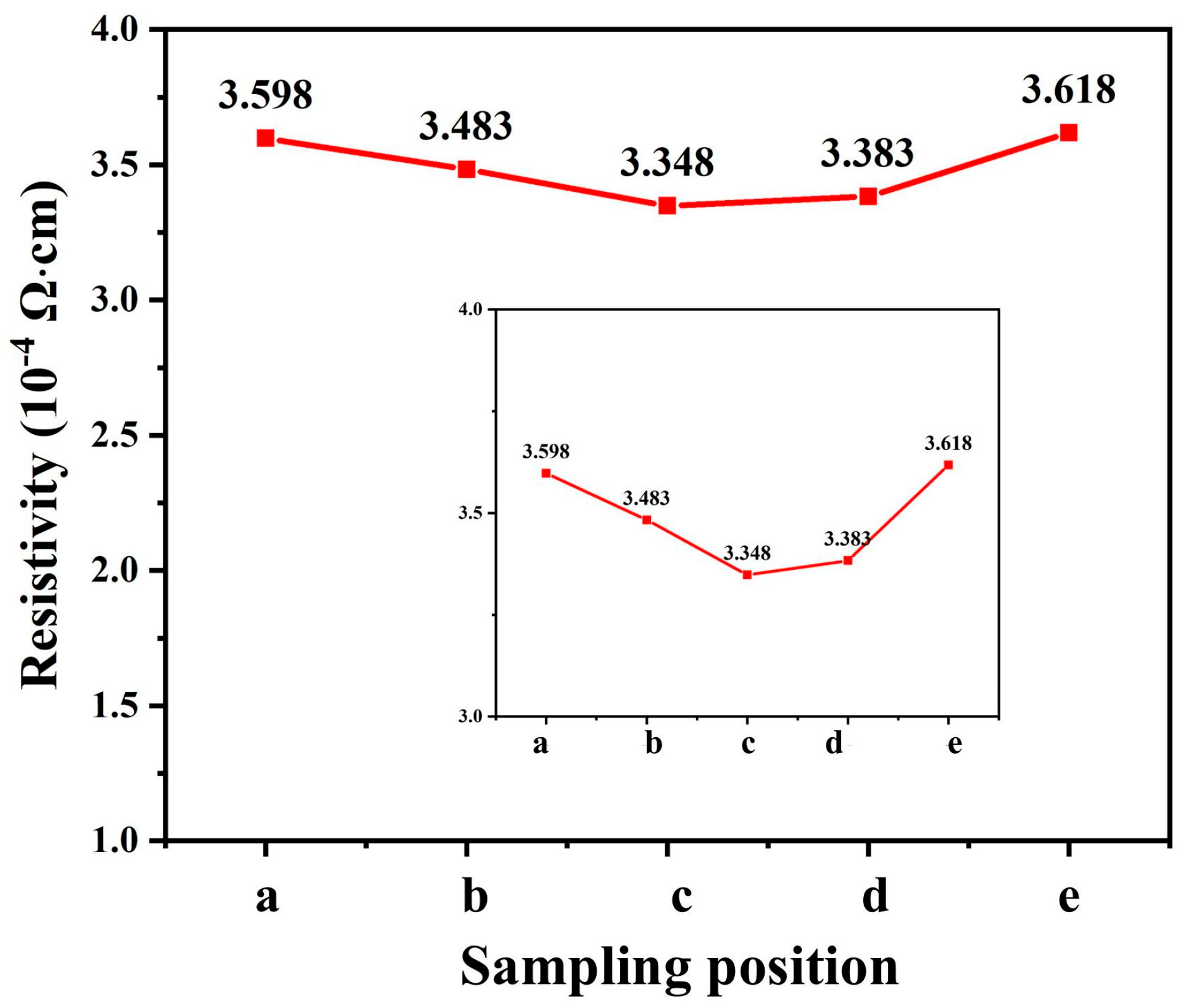
Figure 8 shows the resistivity of the samples taken from the different positions along the ITTO segment. It is evident that all the samples, irrespective of their position, exhibit low resistivity, with an average value of 3.486 × 10⁻⁴ Ω·cm. Notably, the minimum resistivity of 3.348 × 10⁻⁴ Ω·cm is observed at the middle position. The resistivity in this work is higher than that of the 10 wt% doped ITO target. This phenomenon can be attributed to the fact that the 3 wt% doping content generates fewer carriers than the 10 wt% doping content. The resistivity variation between different positions ranges from 0.03% to 3.9%. The high uniformity of resistivity is indicative of a uniform structure and composition. Consequently, the prepared segment with good conductivity is well suited for utilization in direct current sputtering model, facilitating the deposition of transparent conductive oxide films.
As reported in reference [32], the 3 wt% SnO2-doped ITO target sintered at 1590 °C via a conventional sintering method exhibits a large grain size of about 50 μm, a relative density of 99%, and a resistivity of 2.3 × 10⁻⁴ Ω·cm. Comparative analysis of these parameters between ITO and ITTO reveals that the ITTO segment can achieve high density, low resistivity, and fine grains at a lower sintering temperature. These advancements are particularly advantageous for the industrial-scale fabrication of sputtering targets and film deposition by magnetron sputtering.

4. Conclusions

In summary, aiming for sintering densification and the fabrication of cylindrical segments of In2O3-based sputtering targets with low doping levels, TiO2- and SnO2-doped In2O3-based segments with large size and hollow structure were investigated. The ITTO segment exhibited a single cubic bixbyite phase, and the sintering densification of the segment was promoted by the TiO2 sintering additive. The segment exhibited a dense microstructure, transcrystalline fracture, fine grains, and uniform element distribution. The experimental results demonstrate that low resistivity and high density were achieved, with the average resistivity and density measuring 99.49% and 3.486 × 10⁻⁴ Ω·cm, respectively. The samples collected from five distinct positions along the 700 mm length segment demonstrated high uniformity in resistivity and density for the ITTO segment. The results obtained in this work reveal the possibility of fabricating high-quality In2O3 segments for further assembly of long cylindrical targets.

Author Contributions

Conceptualization, H.X. and J.X.; methodology, J.X. and Y.Y.; formal analysis, G.Z. and L.Y.; investigation, F.W. and Y.Y.; resources, H.X.; data curation, F.W. and J.X.; writing—original draft preparation, J.X.; writing—review and editing, Y.Y. and H.X.; project administration, H.X.; funding acquisition, H.X. and J.X. All authors have read and agreed to the published version of the manuscript.

Funding

This work was financially supported by the Joint Fund of NSFC-Guangxi (U21A2065), the National Natural Science Foundation of China (62464004), and the Science and Technology Major Project of Guangxi (AA21077018).

Data Availability Statement

The original contributions presented in this study are included in the article. Further inquiries can be directed to the corresponding author(s).

Acknowledgments

The author acknowledges the support of the Engineering Research Center of Electronic Information Materials and Devices, Ministry of Education, Guangxi Key Laboratory of Information Materials, Guilin University of Electronic Technology, and Luoyang Crystal Union Photoelectric Materials Co., Ltd.

Conflicts of Interest

Author Yuan Yao was employed by the company Luoyang Crystal Union Photoelectric Materials Co., Ltd. The remaining authors declare that the research was conducted in the absence of any commercial or financial relationships that could be construed as a potential conflict of interest. The funding sponsors had no role in the design of the study; in the collection, analyses, or interpretation of data; in the writing of the manuscript, and in the decision to publish the results.

References

  1. Varshney, D.; Prakash, J.; Singh, G. Indium tin oxide nanoparticles induced tunable dual alignment in nematic liquid crystal. J. Mol. Liq. 2023, 374, 121264. [Google Scholar] [CrossRef]
  2. Koh, T.; Choi, J.; Lee, S.; Yoo, S. Optical outcoupling enhancement in organic light-emitting diodes: Highly conductive polymer as a low-index layer on microstructured ITO electrodes. Adv. Mater. 2010, 22, 1849–1853. [Google Scholar] [CrossRef]
  3. Li, W.; Liu, X.; Zhang, J.; Wang, H.; Yuan, C.; Lin, S.; Chen, C.; Shen, C.; Tang, J.; Li, J.; et al. Reactive plasma deposition of ITO as an efficient buffer layer for inverted perovskite solar cells. Adv. Mater. 2025, 37, 2417094. [Google Scholar] [CrossRef] [PubMed]
  4. Park, D.-P.; Park, W.-H.; Song, J.-K.; Kim, S.S. High-performance ITO thin films for on-cell touch sensor of foldable OLED displays. J. Inf. Disp. 2022, 23, 77–85. [Google Scholar] [CrossRef]
  5. Yamamoto, A.; Yokoyama, D.; Takahashi, M.; Fuke, T.; Shibayama, S.; Yamasaki, A.; Lin, C. Highly reliable dielectric interlayers for flexible displays and E-paper. Inf. Disp. 2022, 38, 19–23. [Google Scholar] [CrossRef]
  6. Robb, A.J.; Duca, Z.A.; White, N.; Woodell, P.; Ward, P.A. Influence of oxygen on the optical and electrical properties of magnetron-sputtered indium tin oxide thin films at ambient temperature. Thin Solid Film. 2024, 788, 140152. [Google Scholar] [CrossRef]
  7. Seok, H.J.; Lee, D.K.; Kim, H.K. Multicoated flexible indium tin oxide electrodes fabricated using magnetron sputtering and arc plasma ion plating for flexible perovskite solar cells. ACS Appl. Mater. Interfaces 2024, 16, 47961–47972. [Google Scholar] [CrossRef]
  8. Musschoot, J.; Depla, D.; Buyle, G.; Haemers, J.; De Gryse, R. Influence of the geometrical configuration on the plasma ionization distribution and erosion profile of a rotating cylindrical magnetron: A Monte Carlo simulation. J. Phys. D Appl. Phys. 2006, 39, 3989. [Google Scholar] [CrossRef]
  9. Garg, R.; Gonuguntla, S.; Sk, S.; Iqbal, M.S.; Dada, A.O.; Pal, U.; Ahmadipour, M. Sputtering thin films: Materials, applications, challenges and future directions. Adv. Colloid Interface Sci. 2024, 330, 103203. [Google Scholar] [CrossRef]
  10. Li, X.Y.; Depla, D.; Leroy, W.P.; Haemers, J.; De Gryse, R. Influence of deposition on the reactive sputter behaviour during rotating cylindrical magnetron sputtering. J. Phys. D Appl. Phys. 2008, 41, 035203. [Google Scholar] [CrossRef]
  11. Brodie, I.; Lamont, L.T., Jr.; Jepsen, R.L. Production of high-energy neutral atoms by scattering of ions at solid surfaces and its relation to sputtering. Phys. Rev. Lett. 1968, 21, 1224. [Google Scholar] [CrossRef]
  12. Depla, D.; Li, X.Y.; Mahieu, S.; Van Aeken, K.; Leroy, W.P.; Haemers, J.; De Gryse, R.; Bogaerts, A. Rotating cylindrical magnetron sputtering: Simulation of the reactive process. J. Appl. Phys. 2010, 107, 113307. [Google Scholar] [CrossRef]
  13. Carreri, F.; Sabelfeld, A.; Gerdes, H.; Bandorf, R.; Vergöhl, M.; Bräuer, G. HIPIMS ITO films from a rotating cylindrical cathode. Surf. Coat. Technol. 2016, 290, 65–72. [Google Scholar] [CrossRef]
  14. De Gryse, R.; Haemers, J.; Leroy, W.; Depla, D. Thirty years of rotatable magnetrons. Thin Solid Film. 2012, 520, 5833–5845. [Google Scholar] [CrossRef]
  15. Linss, V. Challenges in the industrial deposition of transparent conductive oxide materials by reactive magnetron sputtering from rotatable targets. Thin Solid Film. 2017, 634, 149–154. [Google Scholar] [CrossRef]
  16. Utsumi, K.; Iigusa, H.; Tokumaru, R.; Song, P.K.; Shigesato, Y. Study on In2O3-SnO2 transparent and conductive films prepared by dc sputtering using high density ceramic targets. Thin Solid Film. 2003, 445, 229–234. [Google Scholar] [CrossRef]
  17. Li, W.-B.; La, Z.-B.; Wu, W.-Q.; Li, Y.-Z.; Pe, X.-J.; Xu, G.-Q. Application progress of hot isostatic pressing technology in transparent ceramics. Adv. Ceram. 2023, 44, 117–128. [Google Scholar]
  18. Langer, J.; Hoffmann, M.J.; Guillon, O. Electric field-assisted sintering and hot pressing of semiconductive zinc oxide: A comparative study. J. Am. Ceram. Soc. 2011, 94, 2344–2353. [Google Scholar] [CrossRef]
  19. Bocanegra-Bernal, M.H. Hot isostatic pressing (HIP) technology and its applications to metals and ceramics. J. Mater. Sci. 2004, 39, 6399–6420. [Google Scholar] [CrossRef]
  20. Zheng, L.; Liu, M.; Zhang, H.; Zheng, Z.; Wang, Z.; Cheng, H.; Wang, P.; Liu, Y.; Huang, B. Fabrication of ZnO ceramics with defects by spark plasma sintering method and investigations of their photoelectrochemical properties. Nanomaterials 2021, 11, 2506. [Google Scholar] [CrossRef]
  21. Liang, F.; Liu, J. Sintering, microstructure and electricity properties of ITO targets with Bi2O3-Nb2O5 addition. Ceram. Int. 2017, 43, 5856–5861. [Google Scholar] [CrossRef]
  22. Akhmedov, A.K.; Asvarov, A.S.; Makhmudov, S.S.; Kanevsky, V.M. Fabrication of segments for ZnO-based tube ceramic targets by the spark plasma sintering method. Ceramics 2023, 6, 1302–1313. [Google Scholar] [CrossRef]
  23. Qin, K.; Mei, F.; Yuan, T.; Li, R.; Jiang, J.; Niu, P.; Chen, H. Effects of sintering processes on the element chemical states of In, Sn and O in ITO targets. J. Mater. Sci. Mater. Electron. 2018, 29, 7931–7940. [Google Scholar] [CrossRef]
  24. Mei, F.; Qin, K.; Mei, F.; Yuan, T.; Liu, W.; Li, R.; Chen, L. Microstructure, grain orientation, and properties of ITO ceramics sintered with various heating rates. Int. J. Appl. Ceram. Technol. 2019, 16, 654–665. [Google Scholar] [CrossRef]
  25. Kim, J.H.; Seong, T.Y.; Ahn, K.J.; Chung, K.B.; Seok, H.J.; Seo, H.J.; Kim, H.K. The effects of film thickness on the electrical, optical, and structural properties of cylindrical, rotating, magnetron-sputtered ITO films. Appl. Surf. Sci. 2018, 440, 1211–1218. [Google Scholar] [CrossRef]
  26. Lippens, P.; Büchel, M.; Chiu, D.; Szepesi, C. Indium-tin-oxide coatings for applications in photovoltaics and displays deposited using rotary ceramic targets: Recent insights regarding process stability and doping level. Thin Solid Film. 2013, 532, 94–97. [Google Scholar] [CrossRef]
  27. Medvedovski, E.; A Alvarez, N.; Szepesi, C.J.; Yankov, O.; Lippens, P. Advanced indium tin oxide ceramic sputtering targets (rotary and planar) for transparent conductive nanosized films. Adv. Appl. Ceram. 2013, 112, 243–256. [Google Scholar] [CrossRef]
  28. David, C.; Tinkham, B.; Prunici, P.; Panckow, A. Highly conductive and transparent ITO films deposited at low temperatures by pulsed DC magnetron sputtering from ceramic and metallic rotary targets. Surf. Coat. Technol. 2017, 314, 113–117. [Google Scholar] [CrossRef]
  29. Zhu, H.H.; Fuh, J.Y.H.; Lu, L. The influence of powder apparent density on the density in direct laser-sintered metallic parts. Int. J. Mach. Tools Manuf. 2007, 47, 294–298. [Google Scholar] [CrossRef]
  30. Wu, F.; Wang, T.; Xu, J.; Zhu, G.; Shang, F.; Xu, H. Microstructure and resistivity of ITO targets sintered by cold and microwave sintering for solar cell applications. Adv. Appl. Ceram. 2024, 123, 121–129. [Google Scholar] [CrossRef]
  31. Kim, S.M.; Seo, K.H.; Lee, J.H.; Kim, J.J.; Lee, H.Y.; Lee, J.S. Preparation and sintering of nanocrystalline ITO powders with different SnO2 content. J. Eur. Ceram. Soc. 2006, 26, 73–80. [Google Scholar] [CrossRef]
  32. Xu, J.W.; Yang, L.; Wang, H.; Zhu, G.; Xu, H.; Zhou, C.; Yuan, C.; Yang, Z. Sintering behavior and refining grains of high density tin doped indium oxide targets with low tin oxide content. J. Mater. Sci. Mater. Electron. 2016, 27, 3298–3304. [Google Scholar] [CrossRef]
  33. Yi, C.X.; Zhang, H.T.; Wang, S.K.; Han, G.S.; Liu, Z.L.; Tian, Y.F.; Bao, M.D. Comprehensive effect of grain size and original target morphology on sputtering behavior of magnetron sputtering target. Vacuum 2023, 210, 111866. [Google Scholar] [CrossRef]
  34. Wang, Y.; Chao, Y.; Li, S.; Ze, C.; Wen, M. Mechanisms of nodule formation on Ni-Pt targets during sputtering. Appl. Surf. Sci. 2025, 680, 161420. [Google Scholar] [CrossRef]
  35. Nadaud, N.; Bock, P. Influence of TiO2 additives on the microstructure of In2O3 ceramics. Ceram. Int. 1996, 22, 207–209. [Google Scholar] [CrossRef]
Figure 1. Microstructure of (a) In2O3, (b) SnO2, and (c) TiO2 raw powders.
Ceramics 08 00075 g001
Figure 2. Microstructure of (a) granulated powders and (b) green body.
Ceramics 08 00075 g002
Figure 3. XRD patterns of the samples taken from the different positions along the ITTO segment.
Ceramics 08 00075 g003
Figure 4. (ae) The polished and etched morphologies of the samples taken from the different positions along the ITTO segment; (f) the cross-sectional morphology at position b.
Ceramics 08 00075 g004
Figure 5. (ae) The grain size distribution of the samples taken from the different positions along the ITTO segment.
Ceramics 08 00075 g005
Figure 6. The cross-section morphologies and corresponding elemental distribution of the samples taken from the different positions along the ITTO segment.
Ceramics 08 00075 g006
Figure 7. The relative density of the samples collected from position a to e.
Ceramics 08 00075 g007
Figure 8. The resistivity of the samples collected from position a to e.
Ceramics 08 00075 g008
Disclaimer/Publisher’s Note: The statements, opinions and data contained in all publications are solely those of the individual author(s) and contributor(s) and not of MDPI and/or the editor(s). MDPI and/or the editor(s) disclaim responsibility for any injury to people or property resulting from any ideas, methods, instructions or products referred to in the content.