
Coextrusion of Clay-Based Composites: Using a Multi-Material Approach to Achieve Gradient Porosity in 3D-Printed Ceramics

 , ,
, ,
Abstract
:1. Introduction
2. Materials and Methods
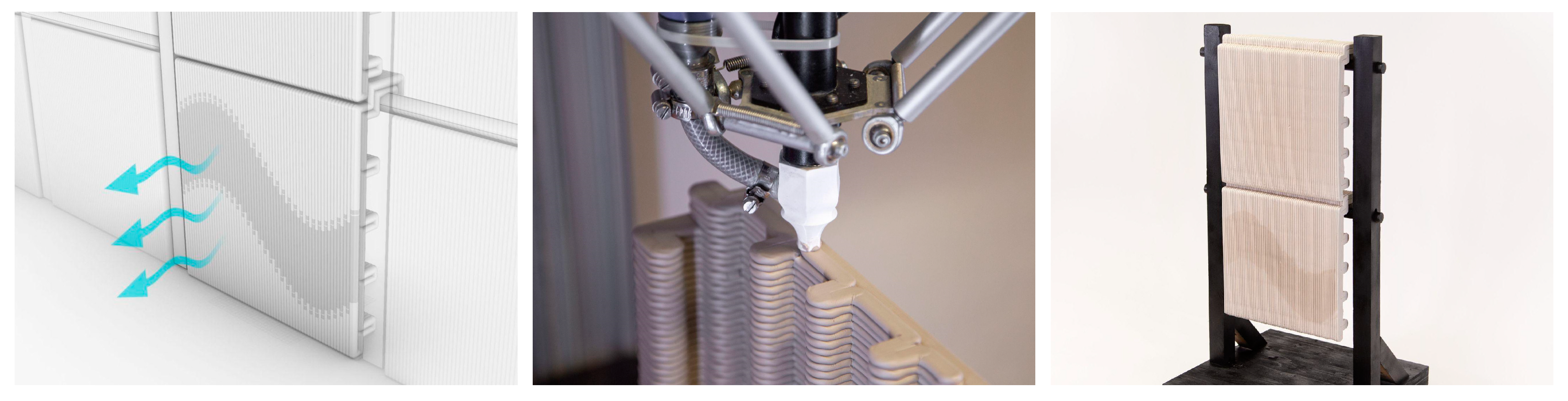
2.1. Hardware Setup
2.1.1. Material Mixtures
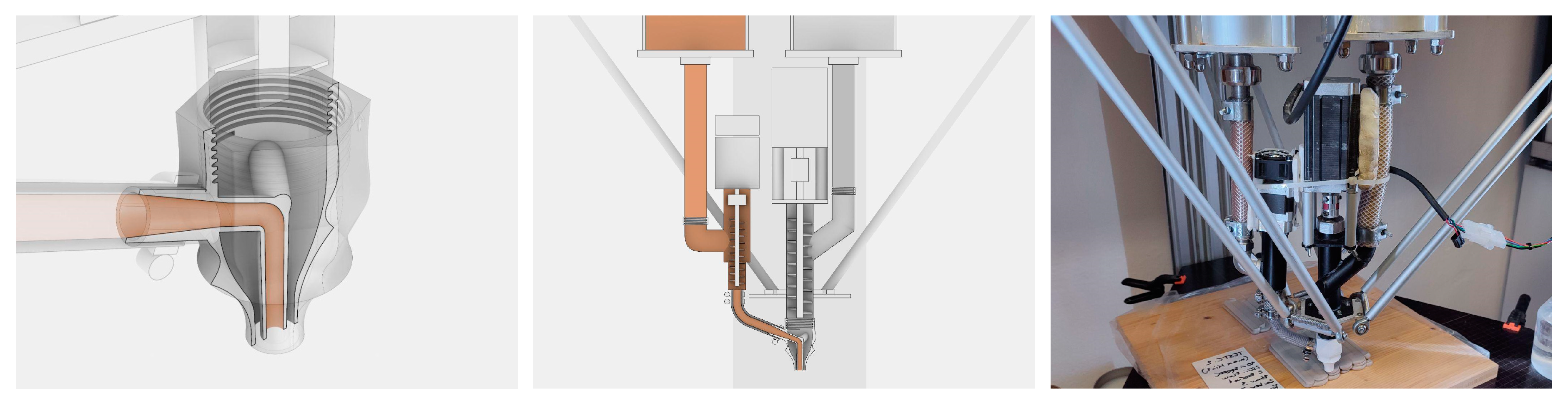
2.1.2. Coextrusion Nozzle
2.1.3. Dual Extruder Setup
2.2. Software
3. Material Experimentation and Results
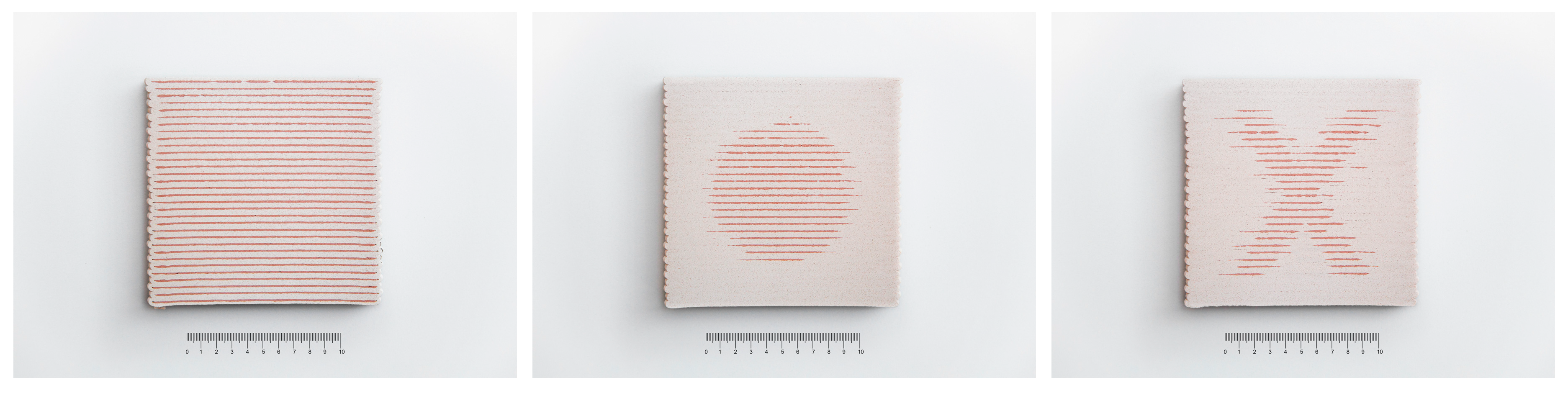
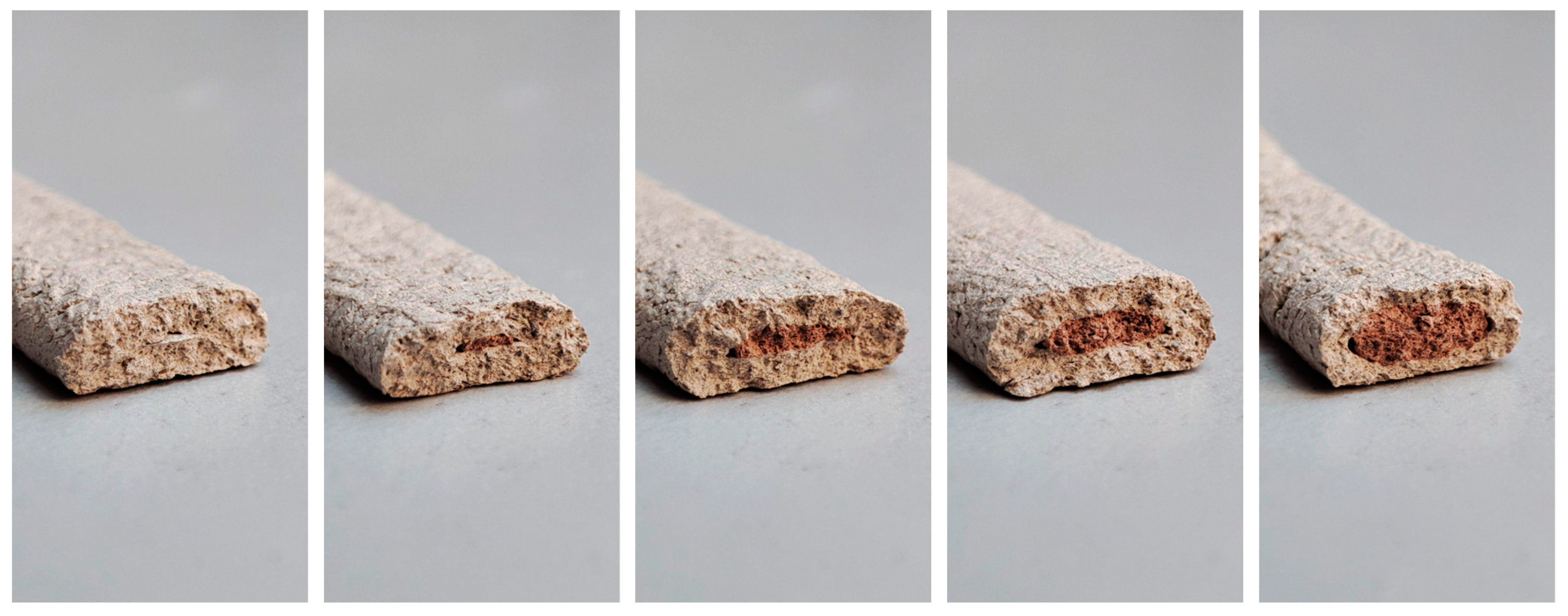
3.1. Experiment 1: On/Off Distribution
3.2. Experiment 2: Gradient Distribution
3.3. Experiment 3: Architectural Prototype
4. Discussion
5. Perspectives
Author Contributions
Funding
Institutional Review Board Statement
Informed Consent Statement
Data Availability Statement
Acknowledgments
Conflicts of Interest
References
- Rael, R.; San Fratello, V. Printing Architecture: Innovative Recipes for 3D Printing; Chronicle Books: New York, NY, USA, 2018. [Google Scholar]
- Chen, Z.; Li, Z.; Li, J.; Liu, C.; Lao, C.; Fu, Y.; Liu, C.; Li, Y.; Wang, P.; He, Y. 3D Printing of Ceramics: A Review. J. Eur. Ceram. Soc. 2019, 39, 661–687. [Google Scholar] [CrossRef]
- Sangiorgio, V.; Parisi, F.; Fieni, F.; Parisi, N. The New Boundaries of 3D-Printed Clay Bricks Design: Printability of Complex Internal Geometries. Sustainability 2022, 14, 598. [Google Scholar] [CrossRef]
- Witte, D. Clay Printing: The Fourth Generation Brickwork; Springer Vieweg: Wiesbaden, Germany, 2022; ISBN 978-3-658-37160-9. [Google Scholar]
- Knaack, U.; Witte, D.; Mohsen, A.; Bilow, M.; Tessmann, O. Imagine 10 Rapids 2.0; nai010 Publishers: Rotterdam, The Netherlands, 2016; ISBN 978-94-6208-293-9. [Google Scholar]
- Oxman, N.; Keating, S.; Tsai, E. Functionally Graded Rapid Prototyping. In Innovative Developments in Virtual and Physical Prototyping; CRC Press: Boca Raton, FL, USA, 2011; pp. 483–489. ISBN 978-0-415-68418-7. [Google Scholar]
- Al-Maharma, A.; Patil, S.; Markert, B. Effects of Porosity on the Mechanical Properties of Additively Manufactured Components: A Critical Review. Mater. Res. Express 2020, 7, 122001. [Google Scholar] [CrossRef]
- Liu, Z.; Zhang, Z.; Ritchie, R. Functional Gradients and Heterogeneities in Biological Materials: Design Principles, Functions, and Bioinspired Applications. Prog. Mater. Sci. 2017, 88, 467–498. [Google Scholar] [CrossRef]
- Siddique, S.; Hazell, P.; Wang, H.; Escobedo, J.; Ameri, A. Lessons from Nature: 3D Printed Bio-Inspired Porous Structures for Impact Energy Absorption—A Review. Addit. Manuf. 2022, 58, 103051. [Google Scholar] [CrossRef]
- Dorey, R.A.; Yeomans, J.A.; Smith, P.A. Effect of Pore Clustering on the Mechanical Properties of Ceramics. J. Eur. Ceram. Soc. 2002, 22, 403–409. [Google Scholar] [CrossRef]
- Smith, D.; Alzina, A.; Bourret, J.; Nait-Ali, B.; Pennec, F.; Tessier-Doyen, N.; Otsu, K.; Matsubara, H.; Elser, P.; Gonzenbach, U. Thermal Conductivity of Porous Materials. J. Mater. Res. 2013, 28, 2260–2272. [Google Scholar] [CrossRef]
- Bandyopadhyay, A.; Heer, B. Additive Manufacturing of Multi-Material Structures. Mater. Sci. Eng. R Rep. 2018, 129, 1–16. [Google Scholar] [CrossRef]
- Minas, C.; Carnelli, D.; Tervoort, E.; Studart, A. 3D Printing of Emulsions and Foams into Hierarchical Porous Ceramics. Adv. Mater. 2016, 28, 9993–9999. [Google Scholar] [CrossRef]
- Kieback, B.; Neubrand, A.; Riedel, H. Processing Techniques for Functionally Graded Materials. Mater. Sci. Eng. A 2003, 362, 81–106. [Google Scholar] [CrossRef]
- Kuipers, T.; Doubrovski, E.; Verlinden, J. 3D Hatching: Linear Halftoning for Dual Extrusion Fused Deposition Modeling. In Proceedings of the 1st Annual ACM Symposium on Computational Fabrication, Cambridge, MA, USA, 12–13 June 2017; Association for Computing Machinery: New York, NY, USA, 2017; pp. 23–32. [Google Scholar]
- Song, H.; Martínez, J.; Bedell, P.; Vennin, N.; Lefebvre, S. Colored Fused Filament Fabrication. ACM Trans. Graph. 2019, 38, 1–11. [Google Scholar] [CrossRef]
- Craveiro, F.; Bártolo, H.; Duarte, J.; Bártolo, P.J. A Multi-Material Extrusion Nozzle for Functionally Graded Concrete Printing. In Industry 4.0–Shaping The Future of The Digital World; CRC Press: Boca Raton, FL, USA, 2020; pp. 130–135. ISBN 978-0-367-82308-5. [Google Scholar]
- Cesarano, I. A Review of Robocasting Technology. MRS Proc. 1998, 542, 133–139. [Google Scholar] [CrossRef]
- Li, W.; Martin, A.; Kroehler, B.; Henderson, A.; Huang, T.; Watts, J.; Hilmas, G.; Leu, M. Fabricating Functionally Graded Materials by Ceramic On-Demand Extrusion with Dynamic Mixing. In Proceedings of the 2018 International Solid Freeform Fabrication Symposium, Austin, TX, USA, 13–15 August 2018; pp. 1087–1099. [Google Scholar]
- Seibold, Z.; Mhatre, S.; López, J.; Alhadidi, S.; Bechthold, M. Janus Printing: Co-Extrusion Based Multi-Material Additive Manufacturing for Ceramics. In Proceedings of the Annual Conference of the Association for Computer-Aided Design in Architecture (ACADIA), Austin, TX, USA, 24–26 October 2019; pp. 576–585. [Google Scholar]
- ELstudio Print&Burn 3D Printing with Clay & More. Available online: https://www.elstudio.nl/?p=1784 (accessed on 11 October 2023).
- Emerging Objects Bad Ombres v.2. Available online: https://emergingobjects.com/project/bad-ombres-v-2/ (accessed on 11 October 2023).
- van Herpt, O. Dunes. Available online: https://oliviervanherpt.com/dunes/ (accessed on 11 October 2023).
- Peters, B. Dyadic Series. Available online: https://www.brian-peters.com/collectibles (accessed on 11 October 2023).
- Vormvrij Dual Extruder for LUTUM 4. Available online: https://vormvrij.nl/brutum/products/brutum-web-store/#!/DUAL-extruder-upgrade-kit/p/177834339/category=47492119 (accessed on 11 October 2023).
- Menchavez, R.; Intong, L.-A. Red Clay-Based Porous Ceramic with Pores Created by Yeast-Based Foaming Technique. J. Mater. Sci. 2010, 45, 6511–6520. [Google Scholar] [CrossRef]
- Grigoriadis, K. Mixed Matters: The Problems of Designing with Multi-Materials. In Proceedings of the What’s the Matter? Materiality and Materialism at the Age of Computation, Barcelona, Spain, 4–6 September 2014; pp. 211–226. [Google Scholar]
- Michalatos, P.; Payne, A.O. Working with Multi-Scale Material Distributions. ACADIA Proc. 2013, 43–50. [Google Scholar] [CrossRef]
- Salmang, H.; Scholze, H.; Telle, R. Keramik; Springer: Berlin/Heidelberg, Germany; New York, NY, USA, 1982; Volume 7. [Google Scholar]
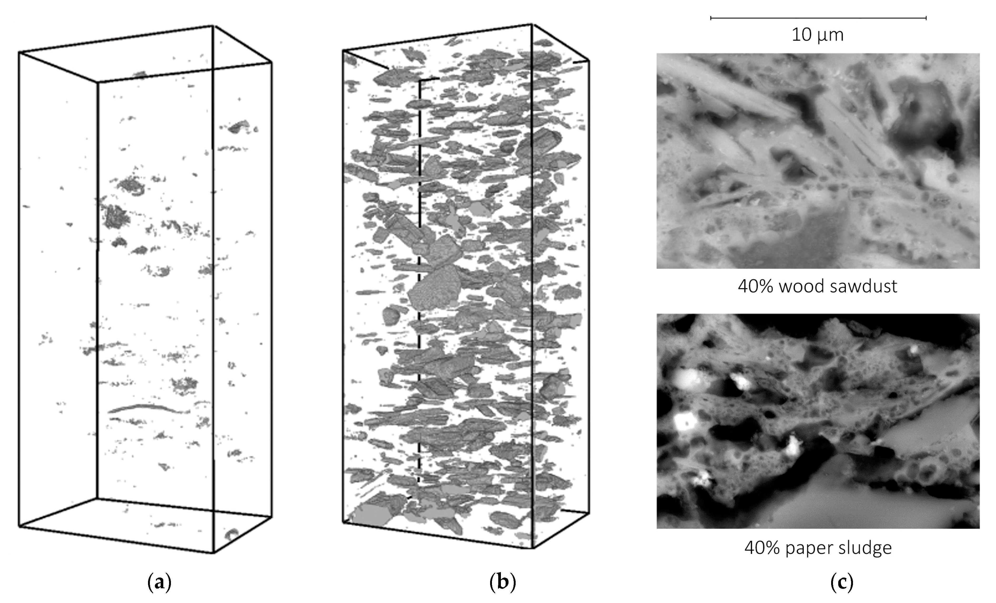
- Kariem, H.; Hellmich, C.; Kiefer, T.; Jäger, A.; Füssl, J. Micro-CT-Based Identification of Double Porosity in Fired Clay Ceramics. J. Mater. Sci. 2018, 53, 9411–9428. [Google Scholar] [CrossRef]
- Saosee, P.; Sajjakulnukit, B.; Gheewala, S.H. Environmental Externalities of Wood Pellets from Fast-Growing and Para-Rubber Trees for Sustainable Energy Production: A Case in Thailand. Energy Convers. Manag. X 2022, 14, 2–11. [Google Scholar] [CrossRef]
- Jauk, J. Termite. 2023. Available online: https://www.food4rhino.com/en/app/termite (accessed on 11 October 2023).
- Keating, S. From Bacteria to Buildings: Additive Manufacturing Outside the Box. Ph.D. Thesis, Massachusetts Institute of Technology, Cambridge, MA, USA, 2016. [Google Scholar]
- Jauk, J.; Gosch, L.; Vašatko, H.; Christian, I.; Klaus, A.; Stavric, M. MyCera. Application of Mycelial Growth within Digitally Manufactured Clay Structures. Int. J. Archit. Comput. 2022, 20, 31–40. [Google Scholar] [CrossRef]
- Yang, H.-Q.; Klug, C.; Schmitz, T. Fiber-Reinforced Clay: An Exploratory Study on Automated Thread Insertion for Enhanced Structural Integrity in LDM. Ceramics 2023, 6, 1365–1383. [Google Scholar] [CrossRef]
- Jauk, J.; Gosch, L.; Vašatko, H.; Königsberger, M.; Schlusche, J.; Stavric, M. Filament-Reinforced 3D Printing of Clay. Materials 2023, 16, 6253. [Google Scholar] [CrossRef]
- Rosenwasser, D.; Mantell, S.; Sabin, J. Clay Non-Wovens: Robotic Fabrication and Digital Ceramics. In Proceedings of the ACADIA 2017 DISCIPLINES & DISRUPTION: 37th Annual Conference of the Association for Computer Aided Design in Architecture, Cambridge, MA, USA, 2–4 November 2017; pp. 2–4. [Google Scholar]
- Alothman, S.; Im, H.C.; Jung, F.; Bechthold, M. Spatial Print Trajectory. In Robotic Fabrication in Architecture, Art and Design 2018; Willmann, J., Block, P., Hutter, M., Byrne, K., Schork, T., Eds.; Springer International Publishing: Cham, Switzerland, 2019; pp. 167–180. [Google Scholar]
- Martin, J.; Fiore, B.; Erb, R. Designing Bioinspired Composite Reinforcement Architectures via 3D Magnetic Printing. Nat. Commun. 2015, 6, 8641. [Google Scholar] [CrossRef]
- Scheder-Bieschin, L.; Margariti, G.; Körner, A.; Suzuki, S.; Knippers, J. Tailoring Self-Formation Fabrication and Simulation of Membrane-Actuated Stiffness Gradient Composites. In Proceedings of the IASS Annual Symposia, Boston, MA, USA, 16–20 July 2018; pp. 1–8. [Google Scholar]
- Hunt, E.; Arthur, H. Hexcrete Modular and Recyclable Paper Clay Formwork. In Proceedings of the eCAADe 41, Graz, Austria, 20–23 September 2023; Volume 1—Digital Design Reconsidered. pp. 429–438. [Google Scholar]
- Buchner, T.; Kiefer, T.; Königsberger, M.; Jäger, A.; Füssl, J. Continuum Micromechanics Model for Fired Clay Bricks: Upscaling of Experimentally Identified Microstructural Features to Macroscopic Elastic Stiffness and Thermal Conductivity. Mater. Des. 2021, 212, 110212. [Google Scholar] [CrossRef]
- Buchner, T.; Königsberger, M.; Jäger, A.; Füssl, J. A Validated Multiscale Model Linking Microstructural Features of Fired Clay Brick to Its Macroscopic Multiaxial Strength. Mech. Mater. 2022, 170, 104334. [Google Scholar] [CrossRef]
- Buchner, T.; Königsberger, M.; Gaggl, W.; Früh, G.; Kiefer, T.; Füssl, J. A Continuum Micromechanics Model Challenged to Predict Thermo-Mechanical Properties of 18 Different Clay Bricks and Sensitivity Analysis Revealing Effects of Compositional and Microstructural Features. Constr. Build. Mater. 2023, 403, 132601. [Google Scholar] [CrossRef]

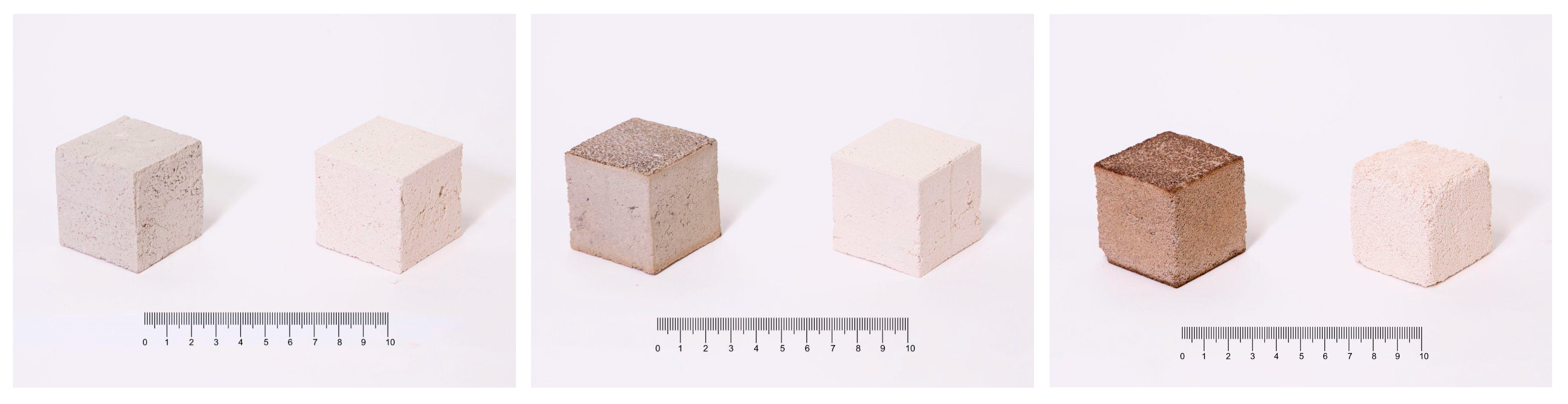
| Weight Ratio of Sawdust, Clay, and Water | Weight Dry | Weight Soaked | Absorption | Brittleness |
|---|---|---|---|---|
| 1:1:1 | 39 g | 111 g | 184.61% | high |
| 1:2:1.05 | 78 g | 130 g | 66.66% | medium |
| 1:3:1.4 | 96 g | 139 g | 44.79% | low |
| 1:3:2 * | 81 g | 118 g | 45.67% | low |
| 1:3:2 | 81 g | 119 g | 46.91% | low |
| 1:3:1.6 | 92 g | 132 g | 43.47% | low |
| 1:3:1.4 * | 94 g | 138 g | 46.80% | low |
| 1:4:1.75 | 104 g | 141 g | 35.57% | low |
| 1:5:2.1 * | 111 g | 145 g | 30.63% | low |
| 1:5:2.1 | 112 g | 143 g | 27.67% | low |
| 1:7:2.8 * | 123 g | 152 g | 23.57% | low |
| 1:7:2.8 | 123 g | 151 g | 22.76% | low |
| 0:1:0.3 | - | - | 10.00% | low |
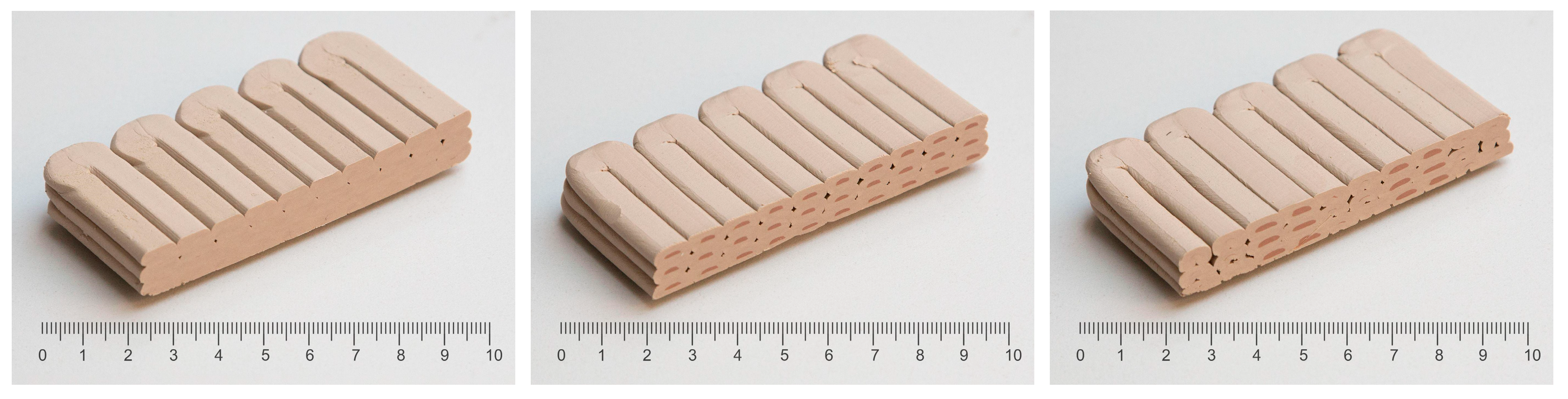
| Travel | Mixture 1 | Mixture 2 | Mixture 3 | Mixture 4 | Mixture 5 | |
|---|---|---|---|---|---|---|
| Tank Pressure | 3/6 [bar] | 3/6 [bar] | 3/6 [bar] | 3/6 [bar] | 3/6 [bar] | 3/8 [bar] |
| Printing Speed | 2000 mm/m | 300 mm/m | 300 mm/m | 300 mm/m | 300 mm/m | 200 mm/m |
| Flow Factor | 0 | 1.2 | 1.1 | 1.1 | 1.0 | 1.0 |
| Reduct Value | 100 | 100 | 60 | 20 | 10 | 0 |
| Material Ratio | 0/0 [%] | 100/0 [%] | 95/5 [%] | 86/14 [%] | 80/20 [%] | 57/43 [%] |
Disclaimer/Publisher’s Note: The statements, opinions and data contained in all publications are solely those of the individual author(s) and contributor(s) and not of MDPI and/or the editor(s). MDPI and/or the editor(s) disclaim responsibility for any injury to people or property resulting from any ideas, methods, instructions or products referred to in the content. |
© 2023 by the authors. Licensee MDPI, Basel, Switzerland. This article is an open access article distributed under the terms and conditions of the Creative Commons Attribution (CC BY) license (https://creativecommons.org/licenses/by/4.0/).
Share and Cite
Jauk, J.; Vašatko, H.; Gosch, L.; Ristoski, K.; Füssl, J.; Stavric, M. Coextrusion of Clay-Based Composites: Using a Multi-Material Approach to Achieve Gradient Porosity in 3D-Printed Ceramics. Ceramics 2023, 6, 2243-2255. https://doi.org/10.3390/ceramics6040136
Jauk J, Vašatko H, Gosch L, Ristoski K, Füssl J, Stavric M. Coextrusion of Clay-Based Composites: Using a Multi-Material Approach to Achieve Gradient Porosity in 3D-Printed Ceramics. Ceramics. 2023; 6(4):2243-2255. https://doi.org/10.3390/ceramics6040136
Chicago/Turabian StyleJauk, Julian, Hana Vašatko, Lukas Gosch, Kristijan Ristoski, Josef Füssl, and Milena Stavric. 2023. "Coextrusion of Clay-Based Composites: Using a Multi-Material Approach to Achieve Gradient Porosity in 3D-Printed Ceramics" Ceramics 6, no. 4: 2243-2255. https://doi.org/10.3390/ceramics6040136
APA StyleJauk, J., Vašatko, H., Gosch, L., Ristoski, K., Füssl, J., & Stavric, M. (2023). Coextrusion of Clay-Based Composites: Using a Multi-Material Approach to Achieve Gradient Porosity in 3D-Printed Ceramics. Ceramics, 6(4), 2243-2255. https://doi.org/10.3390/ceramics6040136