Abstract
The partial replacement of primary raw materials for the production of refractories with recycled ones gains in importance, as it contributes to the conservation of natural resources, energy saving, and reduction in greenhouse gas emissions. In this work, the use of a magnesia–carbon (MgO-C) recyclate in the fractions 3–6, 1–3, and 0–1 mm as a raw material for MgO-C refractories was investigated. The recyclate was examined via optical and scanning electron microscopy. Using mixtures with different recyclate contents up to 82 wt%, MgO-C specimens were prepared to study the influence of the recyclate on their chemical composition, structure, and properties. The substitution of primary raw materials with the recyclate did not cause a decrease in the MgO content analyzed after carbon burnout, but the contents of the individual impurities changed. A comparison of the MgO-C that contains 82 wt% recyclate with the recyclate-free material through computed tomography indicated a change in the size distribution of the MgO grains. The porosity increased, and the cold modulus of rupture decreased with increasing recyclate content, whereas the thermal shock resistance improved. At a recyclate content of 40 wt%, the refractoriness under load was only slightly lower than that of the recyclate-free material.
1. Introduction
Refractories are indispensable for industrial high-temperature processes and, therefore, of enormous economic importance, with around 70% of these materials being used in the steel industry [1]. After their useful life, they can serve as a valuable source of raw materials [2]. Their recycling for the purpose of partial replacement of primary raw materials in the production of refractories has the potential for higher economic and environmental benefits compared with the so-called open-loop recycling applications, such as roadbed aggregates or slag conditioners in steel production [1]. Thus far, only about 7% of the raw materials in the refractory industry come from recycling [1,3]. However, because of the rising costs of raw materials and energy prices, as well as environmental protection requirements, the recycling of refractories as secondary raw materials for refractory production is gaining importance. The benefits of recycling include reduced consumption of natural raw materials, energy savings, less dependence on raw material suppliers, reduced waste to be disposed of in landfills, and a reduction in CO2 emissions [1,2,4]. Disadvantages are the usually higher internal porosity of the recyclate aggregates, resulting in higher porosities of the refractory [1,5,6,7,8], and the often higher impurity contents than primary raw materials [1,4]. Thorough sorting of the used refractories, the proper removal of impurities, such as slag or iron, and appropriate quality assurance management are essential to avoid variations in the quality of the recycled material [1,2,7]. Sorting systems based on laser-induced breakdown spectroscopy (LIBS) have been developed to support sorting [1].
Owing to their high resistance to thermal shock and slags [9], magnesia–carbon (MgO-C) materials are among the most important refractories used in steel production. Their main applications are wear linings in basic oxygen furnaces (converters), electric arc furnaces, and steel treatment ladles [10]. The used refractories from converters are particularly suitable for recycling because they contain relatively few other types of material [7]. In [6], it was estimated that about 40% of the original converter lining is consumed by wear. About half of the remaining 60% is recyclable material, from which secondary raw materials for refractories can be obtained.
The suitability of recycled MgO-C for this purpose may be severely limited if the original MgO-C bricks contained reactive metal powders as antioxidants [6,7]. The most common antioxidant is aluminum (Al). At the operating temperatures during the use of the original MgO-C refractory, aluminum carbide is formed (along with other compounds), with the Al4C3 formation starting above the melting temperature of Al (660 °C) [9]. Aluminum carbide has high reactivity with moisture. As a result, during the manufacturing process of the recyclate-containing refractory, severe cracking may occur if no additional treatments are applied as a countermeasure [1,11,12].
In [11], used MgO-C with high Al content from the converter was subjected to a thermal treatment at 900 °C under oxidizing atmosphere after crushing, grinding, and screening, through which about 90% of the carbon was burned out. The authors did not provide information on the original Al content but reported that the Al2O3 content in the unfractionated recycled material after the aforementioned thermal treatment was 4.7 wt%. MgO-C bricks containing up to 53% of this recyclate were produced. They showed similar properties to standard bricks. Other authors investigated the use of a recyclate obtained from the MgO-C lining material of electric arc and ladle furnaces to produce magnesia bricks and magnesia ramming mixes [8]. The carbon was burned out at 1400 °C in their study. Only the 1–4 mm fraction of the recyclate was used, as impurities usually accumulate in the fine particle fraction. The recyclate content in the refractories was up to 30 wt%. The recyclate-containing specimens showed higher porosities than the reference samples but adequate strengths and slightly improved corrosion resistance. In [4], a MgO-C recyclate in two aggregate size fractions, 1–4 and 4–6 mm, was used without a carbon removal step for the production of MgO-C bricks. The investigated recyclate contents of up to 30 wt% did not worsen the properties of the refractory material.
In the present work, a commercially available MgO-C recyclate was initially examined using optical and scanning electron microscopy. Subsequently, MgO-C formulations with different contents of recycled material up to 82 wt% were developed. Unlike in [4], not only the coarse fractions of MgO-C recyclate were utilized but also a fine fraction (the 0–1 mm fraction). The influence of the recycled MgO-C material on the structure, chemical composition, and properties of MgO-C refractory samples was investigated.
2. Materials and Methods
The MgO-C recyclate R94A1 from Horn & Co. RHIM Minerals Recovery GmbH/Germany, supplied in the aggregate size fractions 3–6, 1–3, and 0–1 mm, was used for the experimental investigations. MgO-C from the converter is the main source of this recyclate, although, to a minor extent, MgO-C from the electric arc furnace is also utilized [13]. The chemical composition of the unfractionated material (without considering the carbon) according to the manufacturer’s specification can be found in Table 1. It is worth mentioning that the Al2O3 content of this MgO-C recyclate can be considered relatively low. Each production batch was carefully controlled, particularly by means of X-ray fluorescence (XRF) spectroscopy. The analysis data of the quality assurance over a period of 12 months are also given in Table 1.

Table 1.
Chemical composition of the recyclate R94A1 (0–6 mm) according to the manufacturer’s specification and data of the quality assurance over a period of 12 months (as of November 2022) [13].
The carbon content was analyzed separately for each recyclate fraction by means of a CS744 carbon–sulfur analyzer (Leco Instrumente GmbH, Mönchengladbach, Germany). It was about 4.9 wt% in the coarsest, 7.6 wt% in the 1–3 mm, and 11.0 wt% in the finest fraction [14].
Furthermore, two grades of Chinese fused magnesia were used: FM97 in three fractions (3–5, 1–3, and 0–1 mm) and FM96DIN. The latter showed a volume-weighted particle size distribution with the following percentile values, determined with a Better Sizer S3 Plus (3P Instruments GmbH, Odelzhausen, Germany): d10 = 15 µm, d50 = 71 µm, d90 = 151 µm [14]. The designation of the fused magnesia (FM) is related to its purity, i.e., 97 and 96 wt%, respectively. Natural flake graphite NFL90/92 (Quingdao Kropfmuehl Graphite Co., Ltd., Quingdao, China) served as a carbon source.
Figure 1 shows images of the recyclate and the primary raw materials taken by means of a digital microscope VHX-2000 (Keyence GmbH, Neu-Isenburg, Germany).

Figure 1.
Raw materials used.
Bakelite® Resin PF9950FL (Hexion GmbH, Iserlohn, Germany), which is a phenolic novolak solved in ethylene glycol, hexamethylenetetramine (Hexion GmbH, Iserlohn, Germany) as curing agent for the novolak, and the modified coal tar pitch powder Carbores® P (Rain Carbon Germany GmbH, Castrop-Rauxel, Germany) served as a binder combination.
For the qualitative analysis of the impurities via energy-dispersive X-ray spectroscopy (EDS), samples of the 0–1 mm fraction of the recyclate and FM97 magnesia were prepared in small graphite tubes and examined under a scanning electron microscope XL-30 ESEM FEG (FEI/Philips, Eindhoven, The Netherlands).
Recyclate aggregates of all three fractions were embedded in epoxy resin, and polished sections were prepared. Optical micrographs were taken using the above-mentioned digital microscope VHX-2000. In addition, the polished sections of the aggregates were investigated under a scanning electron microscope Amber FIB-SEM (Tescan, Brno, Czech Republic) including spot analysis via EDS (Bruker Nano GmbH, Berlin, Germany).
Samples of the 0–1 mm recyclate fraction and the graphite NFL90/92 prepared on conductive carbon pads were also examined in the Amber FIB-SEM. The purpose of the latter investigation was to compare the graphite flakes contained in the recyclate with those of the NFL90/92 graphite.
The formulations for the preparation of MgO-C specimens were based on a mixture of exclusively primary raw materials used in [12]. This mixture is given in Table 2 in the column “R94A1:FM97 = 0:100”. Compared with the base formulation used in our previous work [14], this mixture contained a lower percentage of the 0–1 mm and a higher percentage of the 3–5 mm FM97 fraction. If the graphite was not considered, the base mixture was composed of 23.0 wt% FM97/3–5 mm, 37.0 wt% FM97/1–3 mm, 25.0 wt% FM97/0–1 mm, and 15 wt% FM96DIN. The weight ratio between the R94A1 recyclate and the FM97 magnesia was gradually increased to 50:50, 80:20, and finally 100:0. The percentage of the fine-grained FM96DIN magnesia was left at 15% of the total weight without the graphite. The graphite content in the recyclate-containing mixtures was determined on the basis of the measured carbon contents of the recyclate fractions so that the total carbon content remained approximately constant. The resulting formulations are shown in Table 2. The added amounts of Bakelite PF9950FL, hexamethylenetetramine, and Carbores® P were kept constant for all mixtures and can be found in the same table.
Table 2.
Mixture formulations.
The mixtures were homogenized in a laboratory mortar mixer ToniMIX (Toni Technik Baustoffprüfsysteme GmbH, Berlin, Germany). By uniaxial pressing using a KV270 press (Rucks Maschinenbau GmbH, Glauchau, Germany), sample bars with dimensions of 150 mm × 25 mm × 25 mm and cylindrical specimens with a height and a diameter of 50 mm were produced at a pressure of 150 MPa. By means of thermal treatment with a maximum temperature of 180 °C in air, the novolak contained in the samples was cured. Subsequently, the samples were subjected to heat treatment in a retort filled with coke grit at 1000 °C and with a holding time of 5 h at this temperature to pyrolyze (coke) the binders.
The bulk density and the open porosity after coking were determined from the mass of the dried sample, the apparent mass of the liquid-soaked sample immersed in liquid, and the mass of the soaked sample in air. Toluene was used as the immersion liquid. The measurement was carried out according to DIN EN 993-1, except for the sample dimensions, which were approximately 75 mm × 25 mm × 25 mm.
The coked specimen bars were examined in a computer tomograph CT-ALPHA (ProCon X-Ray GmbH, Sarstedt, Germany) equipped with a 160 kV X-ray transmission tube (Feinfocus Röntgen-Systeme GmbH, Garbsen, Germany) and a Dexela CMOS flat panel X-ray detector 1207 (PerkinElmer Technologies GmbH & Co. KG, Walluf, Germany).
To investigate the chemical composition of the produced MgO-C materials, the samples were ground in a vibrating disk mill using a tungsten carbide grinding set and analyzed by XRF using an XRF spectrometer Bruker S8 Tiger II (Bruker AXS GmbH, Karlsruhe, Germany) after burning out the carbon at 1000 °C.
To evaluate the thermal shock behavior, the coked sample bars to be tested were preheated at 250 °C and then transferred to a furnace preheated to 950 °C, which contained a bed of coke grit to minimize the oxidation of the refractory specimens. After 30 min, the specimens were removed from the furnace, placed on a steel plate, and quenched for 5 min using compressed air (0.1 MPa). The procedure was based on DIN EN 993-11 and modified by using the coke bed. Each sample was subjected to five thermal shocks. The cold modulus of rupture (CMOR) of the specimens after five thermal shocks and that of the sample bars not subjected to thermal shocks was determined based on DIN EN 993-6 using a TIRAtest materials testing machine (TIRA GmbH, Schalkau, Germany). The percentage strength loss caused by the thermal shocks was calculated.
The refractoriness under load (RUL) was determined by means of an RUL/CIC 421 apparatus (Netzsch GmbH, Selb, Germany) on drilled samples with a reduced diameter of 40 mm and a height of 50 mm in order to be able to encase them in coke grit to suppress oxidation during the measurement. The samples were heated under a constant compressive load of 0.2 MPa at a rate of 5 K/min up to a temperature of 1600 °C, and their height change was recorded by means of an inductive displacement transducer.
3. Results and Discussion
3.1. Recyclate Characterization
Figure 2 shows the results of the qualitative elemental analysis of the 0–1 mm MgO-C recyclate fraction compared with the same fraction of the fused magnesia FM97. This fraction was selected because impurities usually accumulate in the finest fraction of raw materials. In both cases, the entire area shown in the corresponding BSE image was included in the analysis. In the EDS spectra of both materials, calcium, silicon, and iron peaks can be seen alongside those of the main constituents. It is worth noting that the impurity peaks of the FM97 spectrum are partially hidden below those of the R94A1 spectrum in the comparison plot. The spectrum of the recyclate suggests an increased aluminum content compared with the fused magnesia. In addition, sulfur was found in the recyclate, resulting from the use of the MgO-C refractory, from which the recyclate was obtained, in the steel industry.

Figure 2.
Results of EDS analysis of the 0–1 mm fraction of fused magnesia FM97 and MgO-C recyclate R94A1. The corresponding BSE micrographs of the analyzed samples can be seen on the right.
Since the recyclate is, expressed simply, a crushed MgO-C refractory, the individual aggregates show a great diversity in terms of their structure and composition. This is illustrated by the optical micrographs in Figure 3. They show polished sections of recyclate aggregates from all three fractions. While some aggregates of the 3–6 mm and the 1–3 mm fraction consisted of magnesia grains less than 1 mm in size that were embedded in a carbonaceous matrix (Figure 3a,b), others also contained fragments of larger magnesia grains (Figure 3d) or consisted mainly of magnesia (Figure 3c,e). Similar diversity is evident in the 0–1 mm fraction (Figure 3f).
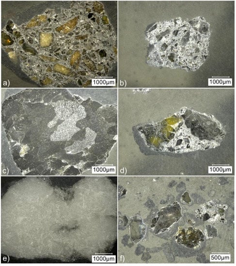
Figure 3.
Optical micrographs of polished sections of recyclate aggregates from the size fractions (a,c,e) 3–6 mm, (b,d) 1–3 mm, and (f) 0–1 mm.
A detail of the microstructure of the recyclate aggregate shown in Figure 3b, which is from the 1–3 mm fraction, can be seen in the scanning electron micrographs in Figure 4. The microstructure of this aggregate is very similar to that of one of the MgO-C recyclate aggregate grades studied in [5]. Graphite flakes and fine-grained magnesia are visible in both the secondary electron (SE) and backscattered electron (BSE) images (Figure 4a,b, respectively), with the BSE image (also called material contrast image) allowing a clearer visual distinction of the phases. In addition to the two main components, the material contained various impurity phases. The results of exemplary EDS spot analyses are presented in Figure 4c,d; the position of the analyzed spots is marked in Figure 4b. Silicon, aluminum, sulfur, and phosphorus were detected as impurities in spot 1. The phase in spot 2 contained silicon, aluminum, potassium, sodium, and barium. Presumably, it is an aluminosilicate. In spot 3, calcium was the impurity element detected along with silicon and aluminum. The impurity phase within the magnesia grain in the lower right corner of the images (spot 4) can be interpreted as calcium magnesium silicate. The determined molar ratio of the components suggested that in this case, it was specifically monticellite (CaO·MgO·SiO2), but at other spots, probably deviating molar ratios would be detected. In addition, evidence of small amounts of phosphorus and aluminum was found in spot 4. Calcium magnesium silicates are the main impurity phases of magnesia-based refractories. Often, merwinite (3CaO·MgO·2SiO2), which was the dominant impurity phase in the MgO-C recyclate aggregates studied in [5], monticellite, and other silicate phases, such as dicalcium silicate (2CaO·SiO2), coexist in these materials [4,5].
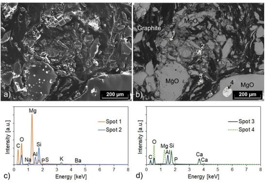
Figure 4.
(a) Secondary electron and (b) backscattered electron micrograph of an aggregate from the recyclate fraction 1–3 mm, and (c,d) related results of EDS spot analyses (with the positions of the spots being marked in (b)). The micrographs show a detail of the polished section seen in Figure 3b.
While the graphite flakes within the recyclate aggregates were of comparable size to those of the NFL90/92 graphite, much smaller graphite flakes were observed at the surface of the aggregates, as shown in our previous publication [14]. Furthermore, fine carbon particles accumulated in the 0–1 mm fraction. Figure 5 shows one of the graphite flakes contained in this fraction compared with the far larger NFL90/92 flakes.
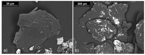
Figure 5.
Backscattered electron micrographs showing (a) a graphite flake contained in the 0–1 mm fraction of the recyclate and (b) graphite NFL90/92.
3.2. Recyclate-Containing MgO-C Refractory Samples
MgO-C refractory samples were prepared and analyzed from the mixtures with the following weight ratio between the recyclate R94A1 and the fused magnesia FM97: 0:100, 50:50, 80:20, and 100:0. This corresponds to the recyclate contents of 0, 39.6, 64.6, and 82.0 wt%, respectively, based on the weight of the total mixture.
In Figure 6, the dependence of the bulk density and the open porosity of the coked MgO-C specimens on the used composition is shown. With the increasing recyclate content, the porosity increased, and the bulk density decreased. Despite the aforementioned differences between the aggregate size distribution of the raw material mixture used here and that used in our previous work [14] (see Section 2), the observed trends were similar. The main cause of these trends can be seen in the structure of the aggregates. In Section 3.1, the diversity in the structure of the recyclate aggregates was shown. Some consisted mainly of magnesia, but the recyclate also contained a large number of aggregates with a high proportion of matrix material. On average, a higher internal porosity of the recyclate aggregates compared with the fused magnesia can be assumed. The higher internal porosity of the recyclate aggregates and the resulting higher porosity of the recyclate-containing refractories is a well-known and common drawback of recycled materials [1,5,6,7,8], as mentioned in Section 1. In addition, another cause (already mentioned in our previous publication [14]) may have contributed to the observed porosity increase. The total carbon content of the mixtures was kept approximately constant by reducing the addition of graphite NFL90/92 with the increasing recyclate content because the recyclate already contained carbon. However, the graphite flakes in the recyclate were enclosed either in the aggregates or, as shown in Section 3.1, were much smaller than those of the graphite NFL90/92. The morphology and the size of the graphite particles have a direct influence on the consistency of the raw materials mixture at a given liquid binder content, on the packing density, and thus on the processability of the mixture, both during mixing and pressing. Furthermore, the graphite particles that are bound in the aggregates cannot act as a lubricant. In [15], it was assumed that increasing graphite contents lead to lower porosities as a result of the lubricating effect of graphite. Investigations in [12] by varying the graphite content of MgO-C samples in the range of 0–16 wt% confirmed this trend, and it was found that this decrease in porosity was primarily due to higher compaction during pressing.
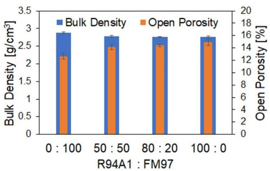
Figure 6.
Bulk density and open porosity of coked MgO-C specimens depending on the used weight ratio of recyclate R94A1 to fused magnesia FM97.
The recyclate content also affects the size distribution of the magnesia grains in the MgO-C refractories, as can be seen from the computed tomographic (CT) images in Figure 7. While the cross-section of the reference sample from exclusively primary raw materials (Figure 7a) shows a rather continuous size distribution, the sample with the composition “R94A1:FM97 = 100:0”, which corresponds to the highest recyclate content used, contains some very large magnesia grains, as well as a higher proportion of small ones (see Figure 7b). The size distribution appears less continuous. Again, the main cause can be seen in the structure of the recyclate aggregates (Figure 3). Many of the aggregates are composed of magnesia grains in a carbonaceous matrix, which increases the proportion of smaller magnesia grains in the refractory. A metallic impurity, presumably steel, is also visible in the CT image of the recyclate-containing sample. The reference sample, on the other hand, seems to contain more broken magnesia coarse grain.
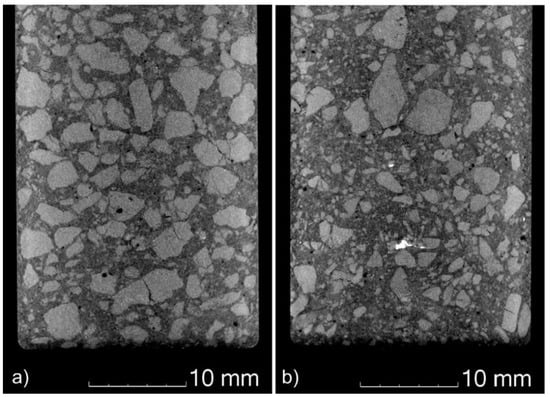
Figure 7.
Computed tomography images showing cross-sectional areas of MgO-C bars of composition (a) R94A1:FM97 = 0:100 and (b) R94A1:FM97 = 100:0.
In addition to the usually higher internal porosity of recyclate aggregates, another frequently occurring disadvantage of recycled materials discussed in the literature is their often lower chemical purity than primary raw materials. Therefore, the chemical composition of the produced materials depending on the recyclate content was analyzed using XRF, with the analysis being performed after carbon burnout. The determined contents of magnesia and the main impurities (CaO, SiO2, Fe2O3, and Al2O3) are listed in Table 3. As can be seen from the MgO contents, no decrease in the purity of the refractories with the increasing recyclate content was observed in the case of the raw materials and formulations used here. However, minor changes occurred in the contents of the individual impurities: That of Al2O3 increased with the recyclate content, whereas those of CaO, SiO2, and Fe2O3 decreased. The analysis results do not indicate a clear dependence of the CaO/SiO2 ratio, which influences the nature and consequently the melting temperature of the silicate impurities, on the recyclate content. For the compositions of R94A1:FM97 = 0:100, 50:50, 80:20, and 100:0, CaO/SiO2 molar ratios of 1.62, 1.46, 1.58, and 1.54, respectively, were calculated from the CaO and SiO2 contents.
Table 3.
Content of magnesia and the main impurities in the produced refractory materials analyzed after carbon burnout.
The results of the strength measurements and the thermal shock tests are given in Figure 8. Thermal shock resistance is a very important property of refractory materials with regard to their application. The CMOR decreased with the increasing recyclate content, but the percentage loss in CMOR as a result of five thermal shocks also decreased, consistent with our previous results [14]. The main reason for the reduced strength can be seen in the higher porosity. Lower strength leads to an increase in the thermal shock parameter R’’’’ [16] and thus to improved thermal shock resistance, which is indicated by the observed reduced strength loss.
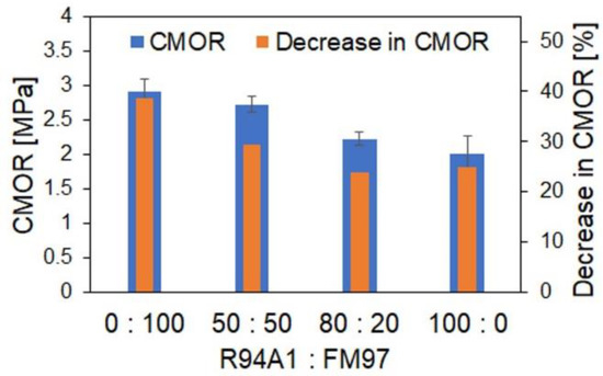
Figure 8.
Cold modulus of rupture (CMOR) of coked MgO-C specimens depending on the used weight ratio of recyclate R94A1 to fused magnesia FM97 and decrease in CMOR as a result of five thermal shocks.
The measurements of the refractoriness under load are a further characteristic test method for refractories. The change in the height of a cylindrical sample is measured under constant load as a function of increasing temperature. The softening behavior is influenced by the mineralogical structure of the material, the amount and viscosity of the melt phases formed with the impurities at high temperatures, and the porosity and pore structure [17]. In Figure 9, the RUL of a sample produced with a recyclate content of 39.6 wt% (R94A1:FM97 = 50:50) and 82.0 wt% (R94A1:FM97 = 100:0) is compared with that of a sample from only primary raw materials (R94A1:FM97 = 0:100). Due to thermal expansion, the height of the specimens initially increased over a wide temperature range. Sample “R94A1:FM97 = 50:50” reached its maximum expansion (dH/H0 = 1.23%) at a temperature of 1569 °C (TdHmax). Up to the upper limit of the measuring range, 1600 °C, no noticeable decrease in the height was recorded (dH/H0 = 1.22%). The reference sample (R94A1:FM97 = 0:100) showed no decrease in sample height up to the measuring range limit. Apart from that, the curves of both samples were very similar. Obviously, at the low recyclate content, the melt phases and structure of the refractory did not yet differ from the recyclate-free sample to such a degree that it would have had a noticeable effect on the RUL. Reduced refractoriness was observed at an increased recycled content. Sample “R94A1:FM97 = 100:0” reached its maximum expansion of dH/H0 = 1.07% at a temperature of 1433 °C. In addition to the influencing factors already mentioned, it can be assumed that the reduced proportion of coarser magnesia grains visible in the CT image in Figure 7b contributed to the reduced RUL. However, the decrease in height from TdHmax up to the measurement range limit of 1600 °C was small. The difference between dH/H0 at TdHmax and dH/H0 at 1600 °C was only 0.04%.
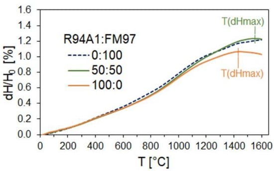
Figure 9.
Refractoriness under load (RUL) of recyclate-containing MgO-C samples of composition R94A1:FM97 = 50:50 and 100:0 in comparison with the reference from only primary raw materials (R94A1:FM97 = 0:100).
4. Conclusions
The partial substitution of primary raw materials for the production of MgO-C refractories by the MgO-C recyclate R94A1, which has a relatively low Al2O3 level, was investigated up to high recyclate contents of 82 wt%.
Through a comparative qualitative EDS elemental analysis of this recyclate and the fused magnesia FM97 using the finest fraction (0–1 mm), where impurities are generally enriched, calcium, silicon, and iron were found in both materials. The EDS spectrum of the recyclate additionally indicated an increased aluminum content. Consequently, the Al2O3 content of the produced MgO-C materials increased with the increasing recyclate content, whereas those of CaO, SiO2, and Fe2O3 decreased. Even though the finest recyclate fraction, which usually contains the highest amount of impurities, was also used for the production of the MgO-C samples, there was no decrease in the MgO content of the refractory material analyzed with XRF after carbon burnout. Minor impurity elements in the recyclate, determined with EDS, were sulfur, phosphorus, potassium, sodium, and traces of barium.
The optical microscopy of the polished sections revealed a wide variety in the structure and composition of the recyclate aggregates. Some were predominantly composed of MgO, but many consisted of MgO grains of different sizes embedded in the carbonaceous matrix. As a result, the size distribution of the MgO grains in the MgO-C refractories was changed, which was evident from comparing a sample that contained 82 wt% of the recyclate with a recyclate-free specimen using computed tomography studies. Furthermore, an increase in the porosity of the MgO-C samples with increasing recyclate content was observed, which could be mainly attributed to the higher on-average internal porosity of the recyclate aggregates. On the one hand, the use of the recyclate resulted in a reduction in the CMOR, but on the other hand, it led to increased thermal shock resistance. Higher recyclate contents caused RUL impairment. At a recyclate content of about 40 wt%, this effect was still minor.
In summary, it can be concluded that the recyclate used is suitable as a raw material for MgO-C refractories. However, some properties deteriorate with increasing recyclate content. In terms of porosity, CMOR, and RUL, the lowest of the recyclate contents used, 40 wt%, is preferable. The highest possible recyclate content depends on the field of application. Therefore, the recyclate content has to be adapted to the specific application requirements. In addition, the achievable properties after up-scaling have to be investigated, since the industrial production of refractories usually leads to lower porosities than the laboratory-scale production of small samples. The highest recyclate content investigated within this study, 82 wt%, will nevertheless only be suitable for applications with comparatively low refractory requirements. In any case, the suitability of the refractories with recyclate content must be verified under operating conditions in the particular device, e.g., in different zones of the ladle.
Author Contributions
Conceptualization, K.M. and C.G.A.; validation, K.M.; investigation, K.M., N.B., J.H. and G.S.; writing—original draft preparation, K.M.; writing—review and editing, K.M., N.B., J.H., G.S. and C.G.A.; visualization, K.M.; supervision, C.G.A.; project administration, C.G.A.; funding acquisition, C.G.A. All authors have read and agreed to the published version of the manuscript.
Funding
This research was funded by Deutsche Forschungsgemeinschaft, grant number 437121912.
Institutional Review Board Statement
Not applicable.
Informed Consent Statement
Not applicable.
Data Availability Statement
Data are available upon request from the corresponding author.
Acknowledgments
We would like to thank the company Horn & Co. RHIM Minerals Recovery GmbH for providing the recyclate and fused magnesia. We especially thank Sinan Sayim, head of quality assurance, and Frank Richter for the information on the recyclate. Furthermore, our thanks go to Marcus Schreiner and Anja Guhl from the Institute of Energy Process Engineering and Chemical Engineering at the TU Bergakademie Freiberg for the XRF analyses.
Conflicts of Interest
The authors declare no conflict of interest. The funders had no role in the design of the study; in the collection, analyses, or interpretation of data; in the writing of the manuscript; or in the decision to publish the results.
References
- Horckmans, L.; Nielsen, P.; Dierickx, P.; Ducastel, A. Recycling of refractory bricks used in basic steelmaking. Resour. Conserv. Recycl. 2019, 140, 297–304. [Google Scholar] [CrossRef]
- Richter, F.; Seifert, H. Refractory raw materials from the steel industry. Refract. Worldforum 2013, 5, 83–86. [Google Scholar]
- McDonald, L. Fostering sustainability in the refractories industry. Am. Ceram. Soc. Bull. 2022, 101, 36–37. [Google Scholar]
- Ludwig, M.; Śnieżek, E.; Jastrzębska, I.; Prorok, R.; Sułkowski, M.; Goławski, C.; Fischer, C.; Wojteczko, K.; Szczerba, J. Recycled magnesia-carbon aggregate as the component of new type of MgO-C refractories. Constr. Build. Mater. 2021, 272, 121912. [Google Scholar] [CrossRef]
- Ludwig, M.; Jastrzębska, I.; Prorok, R.; Sułkowski, M.; Goławski, C.; Szczerba, J. Investigation of recycled magnesia-carbon aggregate obtained with omitting carbon-removal step. In Proceedings of the Unified International Technical Conference on Refractories (UNITECR 2022)—17th Biennial Worldwide Congress on Refractories, Chicago, IL, USA, 15–18 March 2022. [Google Scholar]
- Klages, G.; Naefe, H.; Solmecke, R.; Thiemann, E. Environmental aspects in the application of refractories for converter linings in Germany. In Proceedings of the 1. European Oxygen Steelmaking Congress, Düsseldorf/Neuss, Germany, 21–23 June 1993; pp. 254–259. [Google Scholar]
- Grabner, B.; Kloss, G. Einsatz von recycliertem Magnesia-Kohlenstoffmaterial in pech- und harzgebundenen Steinen. In Proceedings of the XXXVIIth International Colloquium on Refractories, Düsseldorf, Germany, 6–7 October 1994; pp. 146–149. (In German). [Google Scholar]
- Arianpour, F.; Kazemi, F.; Fard, F.G. Characterization, microstructure and corrosion behavior of magnesia refractories produced from recycled refractory aggregates. Min. Eng. 2010, 23, 273–276. [Google Scholar] [CrossRef]
- Ewais, E.M.M. Carbon based refractories. J. Ceram. Soc. Jpn. 2004, 112, 515–532. [Google Scholar] [CrossRef]
- Buchebner, G.; Barthel, H. Magnesia-carbon bricks. In Pocket Manual Refractory Materials: Design, Properties, Testing; Routschka, G., Wuthnow, H., Eds.; Vulkan-Verlag: Essen, Germany, 2008; pp. 183–193. [Google Scholar]
- Fonseca de Lima, D.; de Oliveira Figuereido Junior, A.; Coelho Novais, C.; Lutkenhaus, M.G. Recycling of MgO-C scrap from BOF with high Al content. In Proceedings of the Unified International Technical Conference on Refractories (UNITECR 2011)–12th Biennial Worldwide Conference on Refractories, Kyoto, Japan, 30 October–2 November 2011. paper 1-A-11. [Google Scholar]
- Hampel, M. Beitrag zur Eigenschaftsbewertung von feuerfesten Magnesiakohlenstofferzeugnissen. Ph.D. Thesis, Technische Universität Bergakademie Freiberg, Freiberg, Germany, 2010. (In German). [Google Scholar]
- Sayim, S.; Richter, F.; (Horn & Co. RHIM Minerals Recovery GmbH, Siegen, Germany). Personal Communication, 2022.
- Moritz, K.; Dudczig, S.; Endres, H.G.; Herzog, D.; Schwarz, M.; Schöttler, L.; Veres, D.; Aneziris, C.G. Magnesia-carbon refractories from recycled materials. Int. J. Ceramic Eng. Sci. 2022, 4, 53–58. [Google Scholar] [CrossRef]
- Hayashi, S.; Takahashi, H.; Watanabe, A.; Osaka, A.; Miura, Y. Dependence of mechanical properties of MgO-C bricks on graphite content. J. Tech. Assoc. Refract. Jpn. (TARJ) 1994, 102, 24–29. [Google Scholar] [CrossRef]
- Brochen, E.; Pötschke, J.; Aneziris, C.G. Improved thermal stress resistance parameters considering temperature gradients for bricks in refractory linings. Int. J. Appl. Ceram. Technol. 2014, 11, 371–383. [Google Scholar] [CrossRef]
- Routschka, G.; Granitzki, K.-E. Refractory Ceramics. In Ullmann’s Encyclopedia of Industrial Chemistry; Wiley-VCH: Weinheim, Germany, 2012; Volume 31, pp. 375–376. [Google Scholar]


Disclaimer/Publisher’s Note: The statements, opinions and data contained in all publications are solely those of the individual author(s) and contributor(s) and not of MDPI and/or the editor(s). MDPI and/or the editor(s) disclaim responsibility for any injury to people or property resulting from any ideas, methods, instructions or products referred to in the content. |
© 2023 by the authors. Licensee MDPI, Basel, Switzerland. This article is an open access article distributed under the terms and conditions of the Creative Commons Attribution (CC BY) license (https://creativecommons.org/licenses/by/4.0/).