Article

Sol–Gel Synthesis of Iron-Doped Sepiolite as a Novel Humidity-Sensing Material

by
Ahmed Sabry Afify
1,
Mehran Dadkhah
2 and
Jean-Marc Tulliani
2,*
1
Department of Basic Sciences, The Higher Institute for Engineering, Automotive Technology and Energy, New Heliopolis 11829, Cairo, Egypt
2
Department of Applied Science and Technology, INSTM R.U. Lince Laboratory, Politecnico di Torino, Corso Duca degli Abruzzi 24, 10129 Torino, Italy
*
Author to whom correspondence should be addressed.
Ceramics 2022, 5(3), 575-592; https://doi.org/10.3390/ceramics5030043
Submission received: 21 August 2022 / Revised: 8 September 2022 / Accepted: 10 September 2022 / Published: 15 September 2022
(This article belongs to the Special Issue Advances in Ceramics)

Abstract

:
Nowadays, humidity sensors are attracting a great deal of attention, and there are many studies focusing on enhancing their performances. Nevertheless, their fabrication through facile methods at reasonable cost is a significant factor. In this article, a new magnesium silicate nanopowder was successfully synthesized using a simple and low-cost sol–gel method. Subsequently, modified sepiolite was achieved by the substitution of iron ions in the synthesized nanopowders. The specimens were then characterized by X-ray diffraction, field emission–scanning electron microscopy, X-ray photoelectron spectroscopy, thermogravimetric–differential thermal analysis, infrared spectroscopy, and nitrogen adsorption. Furthermore, humidity sensors were manufactured by screen printing the prepared powders on alumina substrates with interdigitated Pt electrodes. The results showed that the fabricated sensors with modified sepiolite exhibited interesting characteristics for humidity detection.

1. Introduction

In recent decades, due to the importance of relative humidity (RH) control in many industrial processes, as well as for the end-user market, an increasing demand for humidity sensors has been generated for drug preparation, fabrication of paper, the electronics industry, medical equipment, agricultural systems, air conditioners, microwave ovens, and home dehumidifiers [1,2,3,4]. Commercial humidity sensors are mostly based on metal oxides, porous silicon, and polymers, onto which water vapor molecules are adsorbed, changing the electrical properties of the device, such as resistivity and capacity [5]. Many sensing materials have been evaluated for the development of high-performance humidity sensors, such as, for example, metal oxides (Al2O3, Fe2O3, TiO2, SiO2, WO3, ZnO, CuO, ZrO2), perovskites (ZrTiO4, LaFeO3, BaTiO3, LiNbO3, SmCrO3, etc.) and spinels (ZnWoO4, MnWO4, NiWO4, CoWO4, MgCr2O4, ZnCr2O4, MgAl2O4, Fe3O4, etc.) [5,6], as well as carbon-based materials [7,8,9,10,11,12,13,14].
Clay minerals with layered structures can be used in various applications as a result of their high specific surface area, their ion exchange capacity, and their hydration process [15,16,17]. Recently, a considerable body of literature has grown up around the development of new materials that act as natural clay with the aim of controlling their intrinsic features and impurities in order for them to be used as adsorbents, catalysts, and sensors [18,19,20]. Sepiolite, as a natural clay mineral material, attracts a lot of attention in agriculture, construction, and industry due to its unique morphology of nanofibrous specific functional groups, low cost, and environmentally friendly properties [21,22,23,24]. It is commonly found in limestone and calcite marls presumed to be of marine origin, in the absence of aqueous aluminum species. The factors favoring sepiolite genesis include moderately high silica concentrations and low a M g 2 + a H + 2 or moderately low silica concentrations and high a M g 2 + a H + 2 [25]. In addition, if the pH of the environment is in the range from slightly acidic to acidic, sepiolite will not precipitate [25]. Sepiolite is a micro-fibrous clay (it is a hydrous magnesium silicate with the chemical formula Mg8Si12O30(OH)4(H2O)4·8H2O). Its structural units are made of two tetrahedral silica sheets and a discontinuous central layer of octahedral magnesium oxide. This structure leads to the formation of open channels with apertures of 0.36 × 1.06 nm2 that can hold zeolitic water and other small molecules [26]. In addition, sepiolite has a high external specific surface area (SSA) outside the channels (ca. 320 m2/g), like zeolite and silica gels [27], and a low cation exchange capacity. It has been reported that, by leaching the magnesium cations (≥0.33) from sepiolite, an amorphous silica-based phase forms due to the collapse of the sepiolite crystalline structure, in such a way that various cations can be substituted along its octahedral sites to make metal–sepiolite [2]. Several studies have been undertaken on the precipitation of metal ions on minerals of clay [20], owing to the presence of metal ions and clays in nature. Furthermore, modified clay can be a suitable candidate for a variety of applications, including highly sensitive humidity and gas sensors [28]. From an economic point of view, due to the large deposits of clay minerals, it can be used as a support for metal ions. Finally, it was first synthesized by Mizutani et al. using hydrothermal synthesis at 150–200 °C in the presence of natural sepiolite seeds [29].
Thus, the aim of this study was to synthesize an amorphous magnesium silicate nanopowder by means of a simple sol–gel method. The modified sepiolite was also obtained by substitution of Mg2+ ions with iron ions in the sepiolite channels. The prepared powders were characterized by mean of thermogravimetric–differential thermal analysis (TG–DTA), X-ray diffraction, X-ray photoelectron spectroscopy (XPS), field emission–scanning electron microscopy (FE-SEM), and nitrogen adsorption (BET at −196 °C). In addition, the humidity sensors were fabricated by screen printing the modified sepiolite (iron-sepiolite) on alumina substrate in combination with interdigitated Pt electrodes, and their humidity-sensing features were evaluated at ambient temperature (25 °C).

2. Materials

Following the recipe of Narasimharao et al. [30], a magnesium silicate nanopowder was synthesized using a sol–gel method. In brief, 32.4 mL tetraethyl orthosilicate (Si(OC2H5)4, TEOS, Sigma Aldrich, Milan, Italy, reagent grade) was firstly mixed with ethanol at 75 °C for one hour. The pH of the solution was adjusted by the addition of HNO3 (Sigma Aldrich, Milan, Italy, ACS grade). In the meantime, 24.79 g magnesium nitrate hexahydrate (Mg(NO3)2·6H2O, Sigma Aldrich, Milan, Italy, ACS grade) was dissolved in 50 mL distilled water. Subsequently, the prepared solution was added dropwise to the first solution and mixed for 60–90 min. The obtained gel will hereafter be referred to as S1. After washing the gel with pure ethanol (Sigma Aldrich, Milan, Italy, ACS grade), it was dried in an oven overnight and calcinated for 5 h at 120 °C and 500 °C, respectively.
In the second step, with respect to the stoichiometric composition of sepiolite, 10% magnesium ions were substituted by iron ions (Fe3+) using 0.01 mole of Fe(NO3)3·9H2O (Sigma Aldrich, Milan, Italy, ACS grade). In this step, the gelation time was 7 h. In contrast to specimen S1, 20 wt% of obtained gel was washed several times by various ratios of ethanol to distilled water (1:1, 1.5:1 and 3:1), whereas for the last washing, pure ethanol was used. It should be mentioned that, after each step of washing, the separation of formed gel from the liquid was carried out by centrifugation at 3800 rpm for 20 min before re-dispersing it into the new solution. The obtained gel will hereafter be referred to as S1FeSUB. Sonication of the S1FeSUB specimen was carried out by means of an ultrasonic bath for 15 min, while the solution was kept under magnetic stirring for 1 h. To avoid the loss of iron ions after the first step of washing, an ammonia solution was used for the precipitation of iron (and probably magnesium) hydroxide at pH 10. To peptize the washed gel, 2 g of the washed sample was added to a 19.5 mL solution of NH4OH (0.3M; Sigma Aldrich, Milan, Italy, anhydrous) in a sealed container, and it was kept in the oven at 80 °C for 48 h. In this way, it was possible to obtain nanoparticles in solution after transformation into a sol. Subsequently, the obtained sol was dried in the oven and then calcined at 500 °C for two hours.
The third group of specimens was prepared by the addition of 10 wt% Fe3+ ions to the stoichiometric synthetic sepiolite (S1) with the same preparation process of S1FeSUB sample. The obtained sample will hereafter be referred to as S1FeXS.
Then, a screen-printing ink was prepared by dissolving 0.4 g Fe(NO3)3·9H2O (Sigma Aldrich, Milan, Italy, ACS reagent) in 0.625 mL ethanol. Subsequently, 0.066 mL monoethanolamine (Sigma Aldrich, Milan, Italy, ACS reagent) and 0.625 mL terpinol (Emflow, Emca Remex, Linton, UK) were added to the solution under continuous stirring. Finally, 0.68 g of S1 powder was progressively added to the solution. The produced ink was screen printed with a 270-mesh screen onto an alumina substrate with interdigitated Pt electrodes (IDEs; Ferro/ESL 5545, King of Prussia, PA, USA) (400 μm in width and with a gap of 450 μm between each “finger”). The film was dried at room temperature overnight, followed by calcination at 550 °C for one hour (Figure 1).
The powders S1FeSUB and S1FeXS were directly mixed with the Emflow after drying to prepare the ink. Subsequently, the inks were screen printed onto interdigitated Pt electrodes, followed by drying and firing as same as for the sample S1.
It should be noted that, due to the high shrinkage of sensor film prepared with sample S1, it showed poor adhesion onto the alumina substrate (as clearly confirmed by FESEM observations). Whereas the prepared films with powders S1FeSUB and S1FeXS exhibited a better adhesion onto the substrate.

3. Methods

The Particle Size Distribution (PSD) of the calcined powder was determined using laser granulometry (Malvern 3600D, Malvern, UK). For this test, the calcined powder was dispersed in ethanol and sonicated for 10 min in an ultrasonic bath.
X-ray diffraction patterns were recorded employing an X’Pert High Score (Philips, Eindhoven, the Netherlands) analytical diffractometer using Cu Kα radiation at a rate of 0.02°/s in the range of 5° ≤ 2θ ≤ 70°.
X-ray Photoelectron Spectroscopy (XPS) was performed on the prepared powders using a Kα 1063 spectrometer (ThermoFisher, Waltham, MA, USA). The peaks were deconvoluted with a Gauss–Lorenz function by means of the software LabSpec version 5.58.25 (Horiba, Kyoto, Japan).
To evaluate the structural changes and weight loss of the specimens during thermal decomposition, Thermogravimetric–Differential Thermal Analysis (TG–DTA) was performed (Neztsch STA 409, Selb, Germany). To this end, about 50 mg of the obtained powders were placed in an open platinum crucible and heated up to 850 °C with a 10 °C/min rate under static air.
Then, samples were uniaxially pressed in the form of thin, self-supporting wafers (optical density of about 20 mg·cm−2) and studied in a standard vacuum frame (residual pressure below 10−3 mbar) in a home-made IR cell equipped with KBr windows. Spectra were recorded at a resolution of 2 cm−1 on an Equinox 55 spectrophotometer equipped with a mercury cadmium telluride cryodetector (Bruker, Karlsruhe, Germany).
The microstructure of the samples was evaluated by FESEM (Field Emission Scanning Electron Microscopy, Zeiss Merlin, Jena, Germany) after sputtering the surfaces of the samples with chromium.
The BET (Brunauer–Emmet–Teller) specific surface area and average pore diameter of specimens were measured using N2 physisorption at −196 °C (Micrometrics ASAP 2020, Norcross, GA, USA). Specific surface area (SSA) and pore diameters were calculated using the BET method and the Barrett–Joyner–Halenda (BJH) algorithm for isotherm desorption branch, respectively.
Most of the previously described characterization techniques were also used to analyze a natural commercial sepiolite (Tolsa, Pangel S9, Madrid, Spain) for the sake of comparison with the prepared materials.
The humidity sensors were tested in a laboratory apparatus consisting of a thermostated chamber, operating at 25 °C, in such a way that RH could be changed between 0 and 96% in steps of 3 min each [31]. The calibration of the apparatus was carried out with the aim of ensuring a constant airflow during electrical measurement (0.05 L/s). The resistance of the sensor was evaluated by means of an LCR meter (Hioki 3533-01, Tokyo, Japan). During the measurements, the sensors were alimented by an AC tension of 1 V at 1 kHz.
The sensor response (SR%) was expressed as the relative variation of the starting resistance, compared with the resistance measured under gas exposure according to the following equation (Equation (1)):
S R ( % ) = 100   ( R 0 R g ) R 0
where R0 and Rg are the measured resistances of the starting sensors (i.e., under air) and those exposed to gas, respectively.

4. Results and Discussion

4.1. Particle Size Distribution

The D10, D50 and D90 values corresponding to 10, 50 and 90% of the cumulative volume distribution are collected in Table 1. It can be seen that there is a remarkable difference in the particles’ agglomeration: the powders S1FeSUB and S1FeXS have a lower particle size distribution compared to sample S1 following calcination at 500 °C. This can be attributed to the peptization process, which resulted in the powders being less agglomerated in samples S1FeSUB and S1FeXS, while the S1 powder derives from a dried gel.

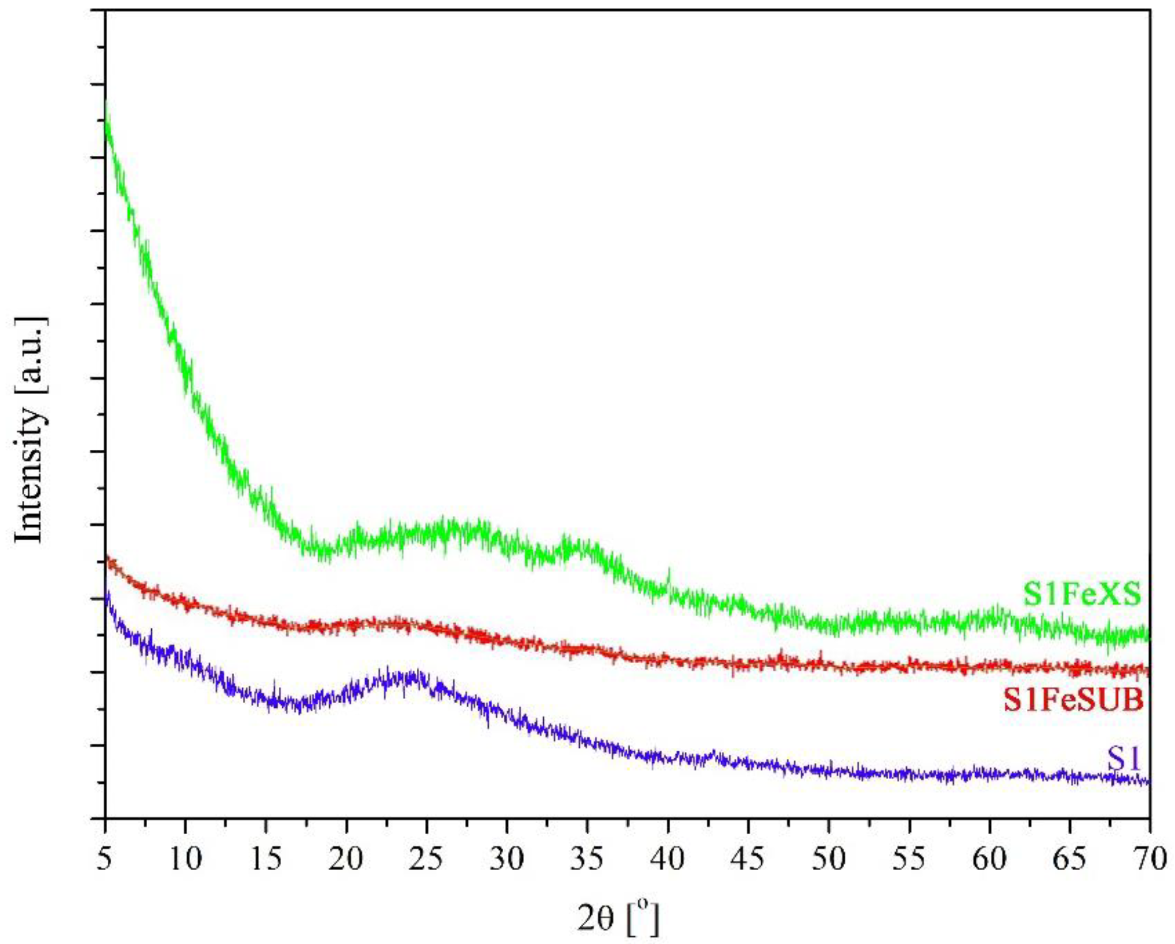
4.2. XRD Measurements

The XRD patterns of the S1, S1FeSUB and S1FeXS samples are presented in Figure 2. Each pattern presents a very broad peak at 2θ ranging from about 19° to 32°, which corresponds to amorphous silicates, and there are no obvious peaks of any crystalline phase. The second hump centered at 2θ~35° in the S1FeXS sample is probably due to iron oxide. In fact, according to the JCPDF card #33-0664, hematite (Fe2O3) presents the most intense peak at 2θ = 33.153° and the second most intense one at 2θ = 35.612° (70% of relative intensity). On the contrary, magnetite (Fe3O4, JCPDF card #19-0629) presents its most intense peak at 2θ = 35.423°, while the second most intense one can be seen at 2θ = 62.516 (with a relative intensity of 40%). Thus, the presence of hematite particles on the surface of the synthetic sepiolite grains is expected. In addition, it seems that during the precipitation of iron and magnesium species at pH 10 in the S1FeSUB and S1FeXS samples, ammonium nitrate was not formed.
The XRD pattern of the commercial sepiolite (not shown here) can be indexed on sepiolite JCPDS card #13-0595 [20,28].

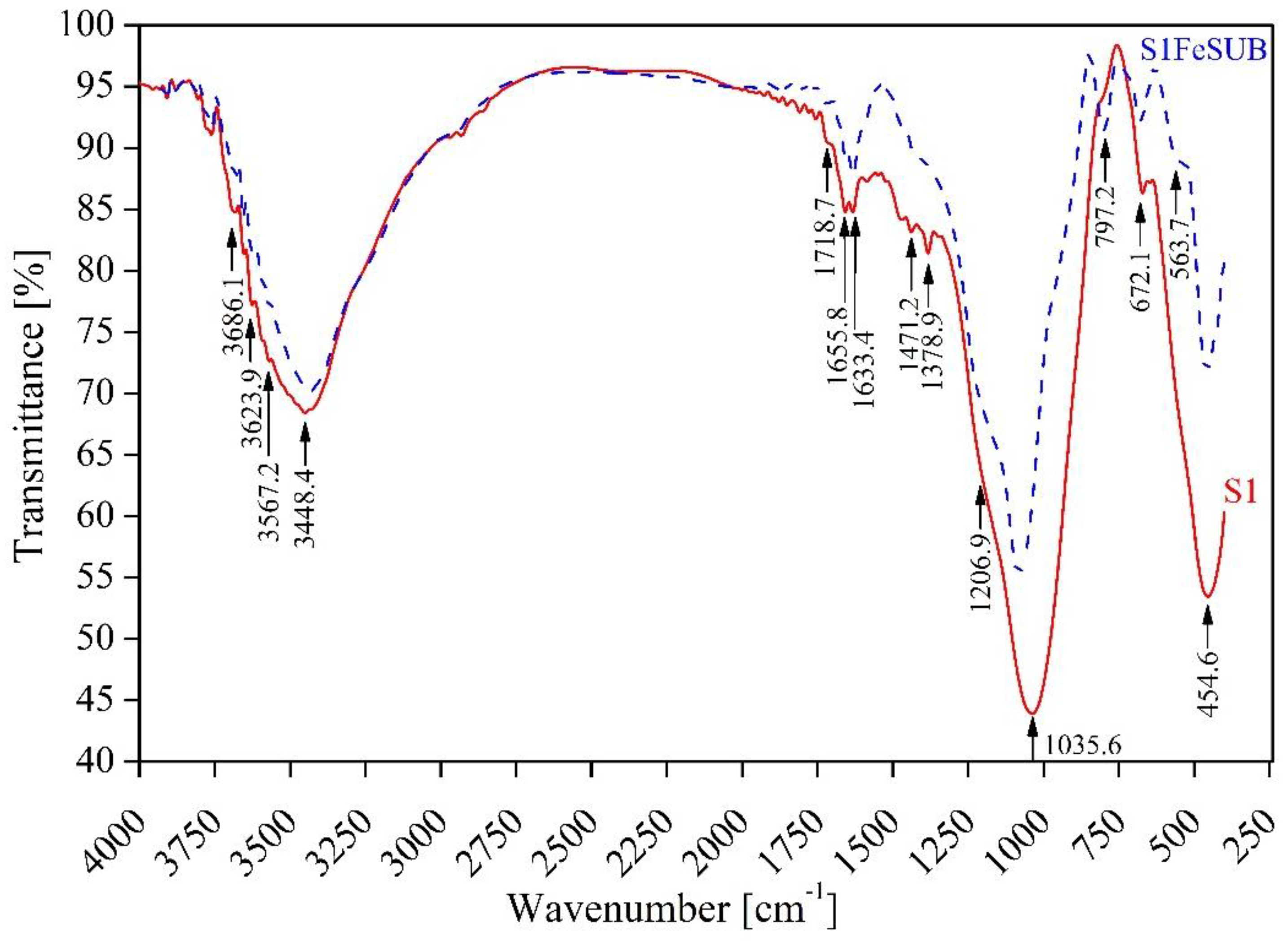
4.3. FTIR Measurements

The FTIR spectra of the S1 and S1FeSUB powders are presented in Figure 3. The peaks located in the range of 3300 to 3600 cm−1 and 3686 cm−1 correspond to O–H stretching vibration and the triple bridge group Mg–OH, respectively (Table 2). Moreover, the presence of a broad band at 3448 cm−1 can be attributed to the stretching vibrations of hydroxyl groups from iron oxide and water. Bands in the range of 800–1200 cm−1 and 1633 cm−1 are associated with the silicate and hydrogen bonds of water molecules in the structure, respectively [32]. The presence of sharp absorption peaks at 1035 cm−1 corresponds to the stretching vibration of the Si–O bond [32]. In fact, the Si–O stretching bands at 1080, 1019 and 980 cm−1 in the FTIR spectrum of natural sepiolite are evident even after thermal treatment at 300 °C [33]. However, if the temperature rises further, the initial sharp peaks are substituted by a single broad absorption band at about 1015 cm−1, indicating that the symmetry of the tetrahedral sheets is distorted [33]. In acid-treated sepiolite, the band at 1000–1200 cm−1, which is due to Si–O–Si vibrations, changes in shape from the natural sepiolite to leached powder with free silica [34]. In addition, bands at 795 and 470 cm−1, which are not present in natural sepiolite, are characteristic of free silica [34].
The peak at 454 cm−1 can be attributed to the deformation mode of MgO6 octahedral units [32]. In the prepared samples, the shoulders observed at 1206.9 cm−1, as well as the band at 797.2 cm−1, can probably be attributed to some free silica. The band at 470 cm−1 may be hindered by the deformation mode of MgO6 octahedral units.
Finally, the bands at 1471.2 and 1378.9 cm−1 could be due to Fe–OH vibration [35]. Interestingly, the data in this figure show that the samples present characteristic vibrations of magnesium silicates, whether iron atoms are present or not [30]. The FTIR spectrum of the S1FeXS sample (not shown here) was very similar to that of the S1FeSUB sample.

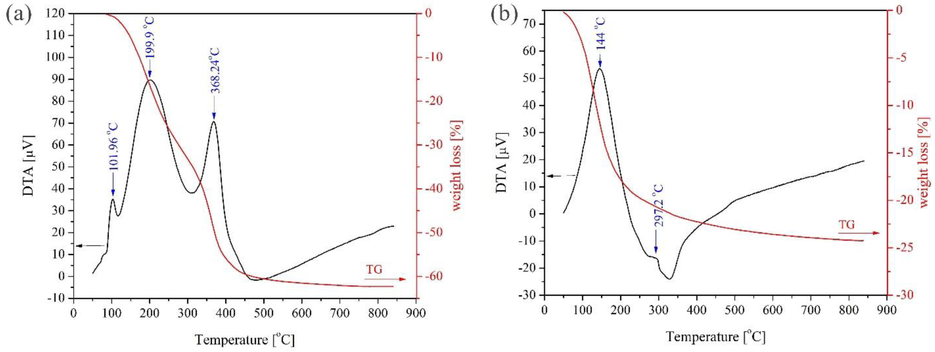
4.4. TG–DTA Measurements

Figure 4a,b show an overall mass loss of 62.2% and 24.2% for the S1 and S1FeSUB samples, respectively. In fact, the washing steps for the S1FeSUB sample led to a loss of by-products in the dried powder.
The thermal behavior of natural sepiolite has been studied in detail in the literature [28,36,37,38,39,40,41,42]. First, superficially adsorbed and zeolitic water molecules are lost at temperatures of up to 170 °C, while, in the temperature range from 300 to 350 °C, half of the coordination water molecules are removed, and the structure folds, entrapping the second half of the coordination water in the collapsed channels. Then, these entrapped water molecules are vaporized at temperatures between 350 and 650 °C, resulting in the formation of anhydride sepiolite [41]. In the case of the S1FeSUB sample in Figure 4b, adsorbing and zeolitic water loss probably occurred at temperatures of up to 200 °C, as was the case for pure sepiolite. Conversely, the weight loss above 350 °C is rather limited. The obtained structures are amorphous magnesium silicates, as reported in [30].
Finally, no exothermic crystallization peak is visible in Figure 4. In [43], iron silicate powders with the composition (in mass%) xFe2O3(100−x)SiO2, where x = 10, 30 and 40, were prepared from TEOS, iron nitrate nonahydrate, and concentrated HNO3, under conditions close to those used in this work. Crystallization of ε-Fe2O3 and of α-Fe2O3 was evidenced on XRD patterns only in the samples heat-treated at 1000 °C. The TG–DTA curve of the S1FeXS sample (not shown here) was very similar to that of the S1FeSUB sample. Finally, these results are in agreement with those derived from the XRD patterns (Figure 2).

4.5. SSA Measurements

It can be seen from Table 3 that the specific surface area of the S1 sample is higher than that of the S1FeSUB sample. The formation of iron species in the S1FeSUB sample with partial clogging of open channels compared to S1 can probably explain the decrease in SSA value.

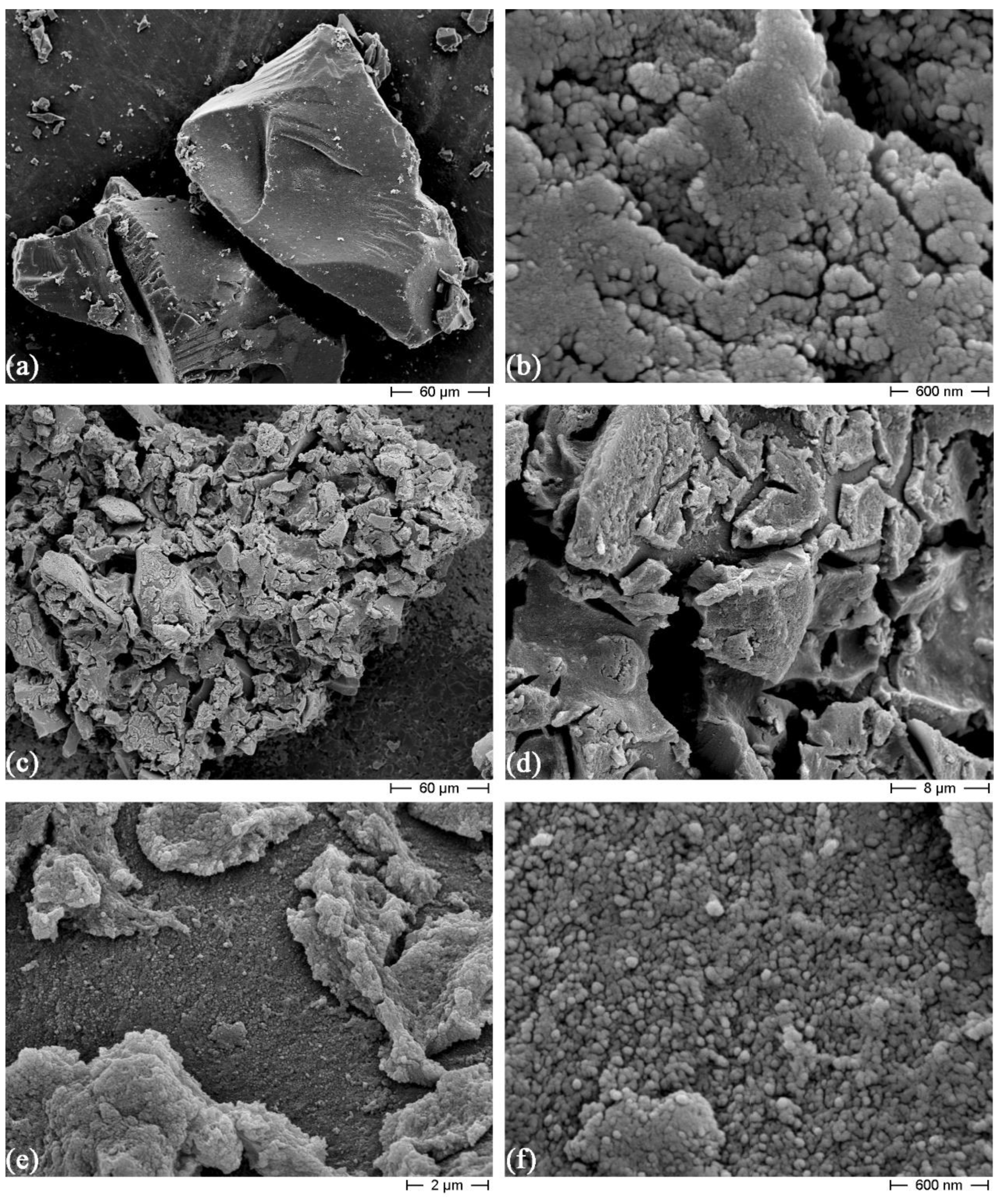
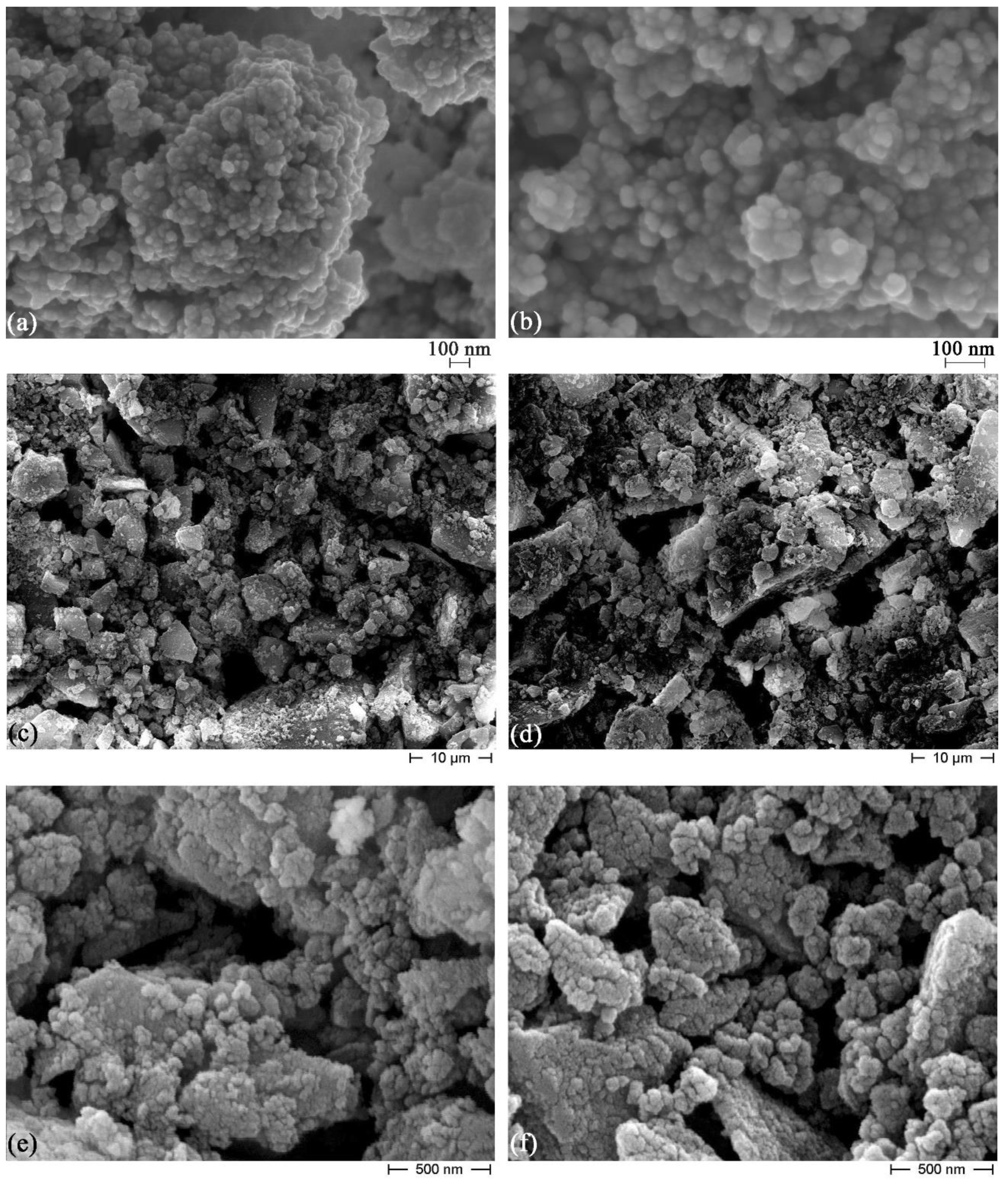
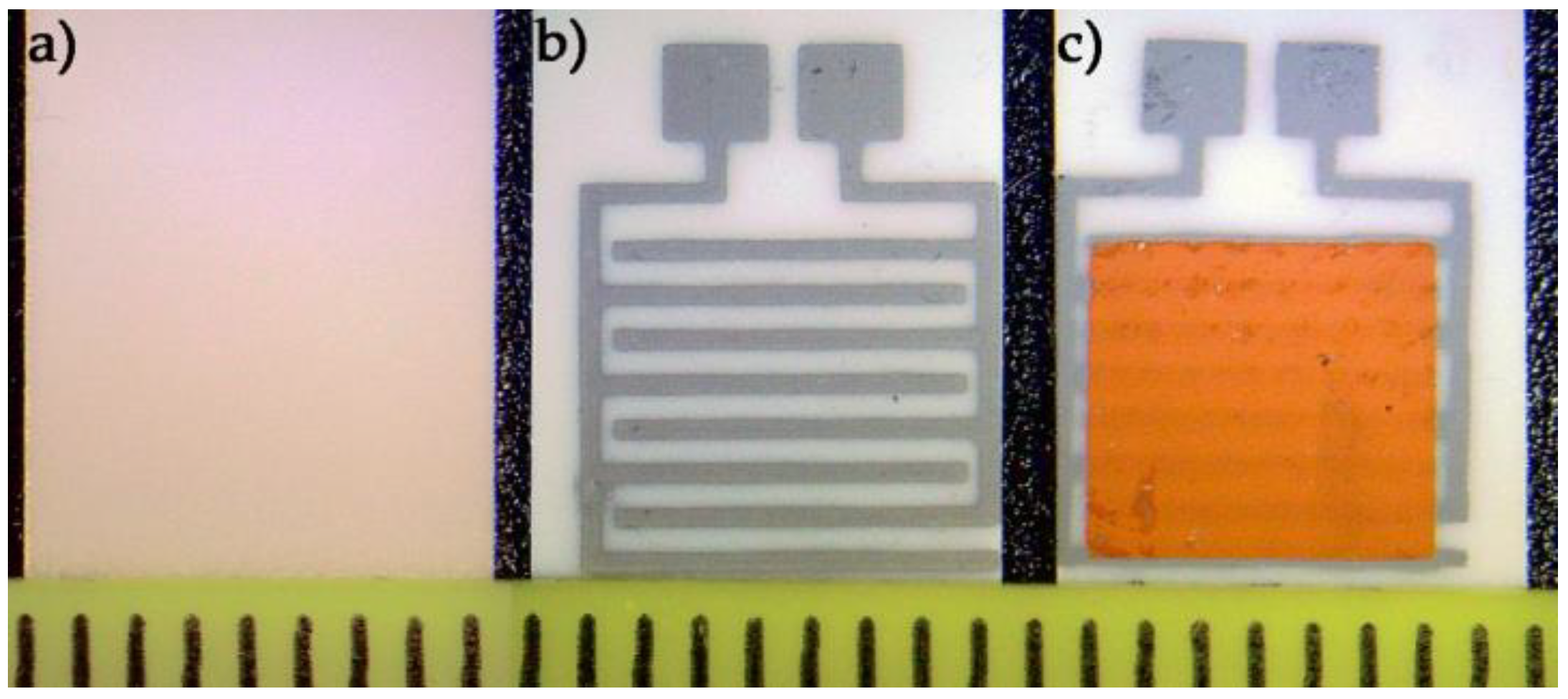
4.6. Microstructural Observations

Figure 5a,b depict FESEM micrographs of the S1 powder after calcination at 500 °C for 5 h. As can be seen, the S1 powder was strongly agglomerated after calcination, which is in line with the laser granulometry measurements.
Figure 5c–f present further microstructural analyses of the screen-printed sensor based on the S1 powder at higher magnifications. As can be clearly seen from these micrographs, the S1 powder prepared by the sol–gel method exhibited limited adhesion onto the alumina substrate due to a high degree of shrinkage, leading to many visible cracks. The high rate of shrinkage is probably due to the loss of by-products in the dried S1 powder, as shown by TG–DTA results (Figure 4a).
Furthermore, the microstructure of the peptized S1FeSUB powder was investigated after drying in the oven (Figure 6a,b). The sol formation during peptization was confirmed on the basis of fine grains being obtained.
Finally, Figure 6c–f compare the FESEM micrographs of screen-printed S1FeSUB and S1FeXS sensors at various magnifications. Both films are porous, which is beneficial for humidity detection.

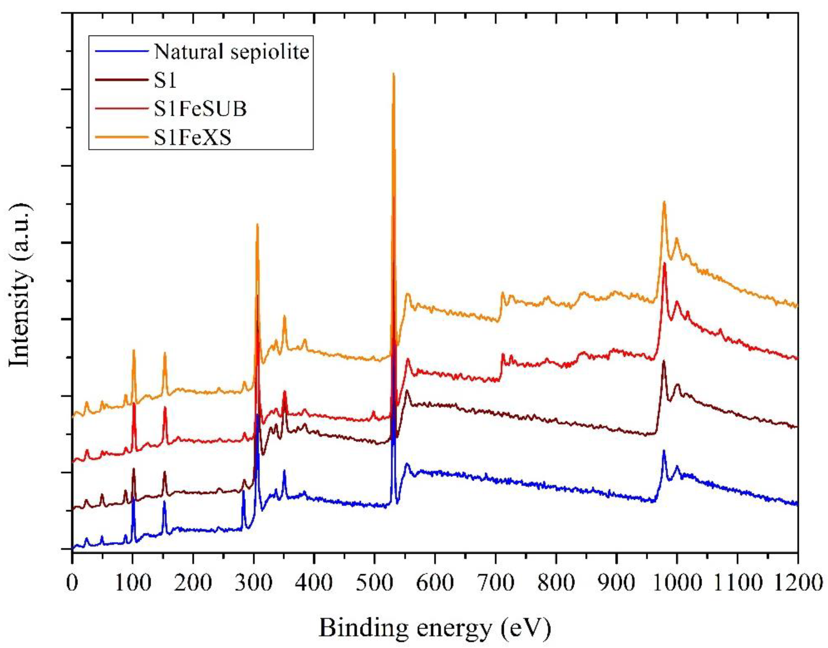
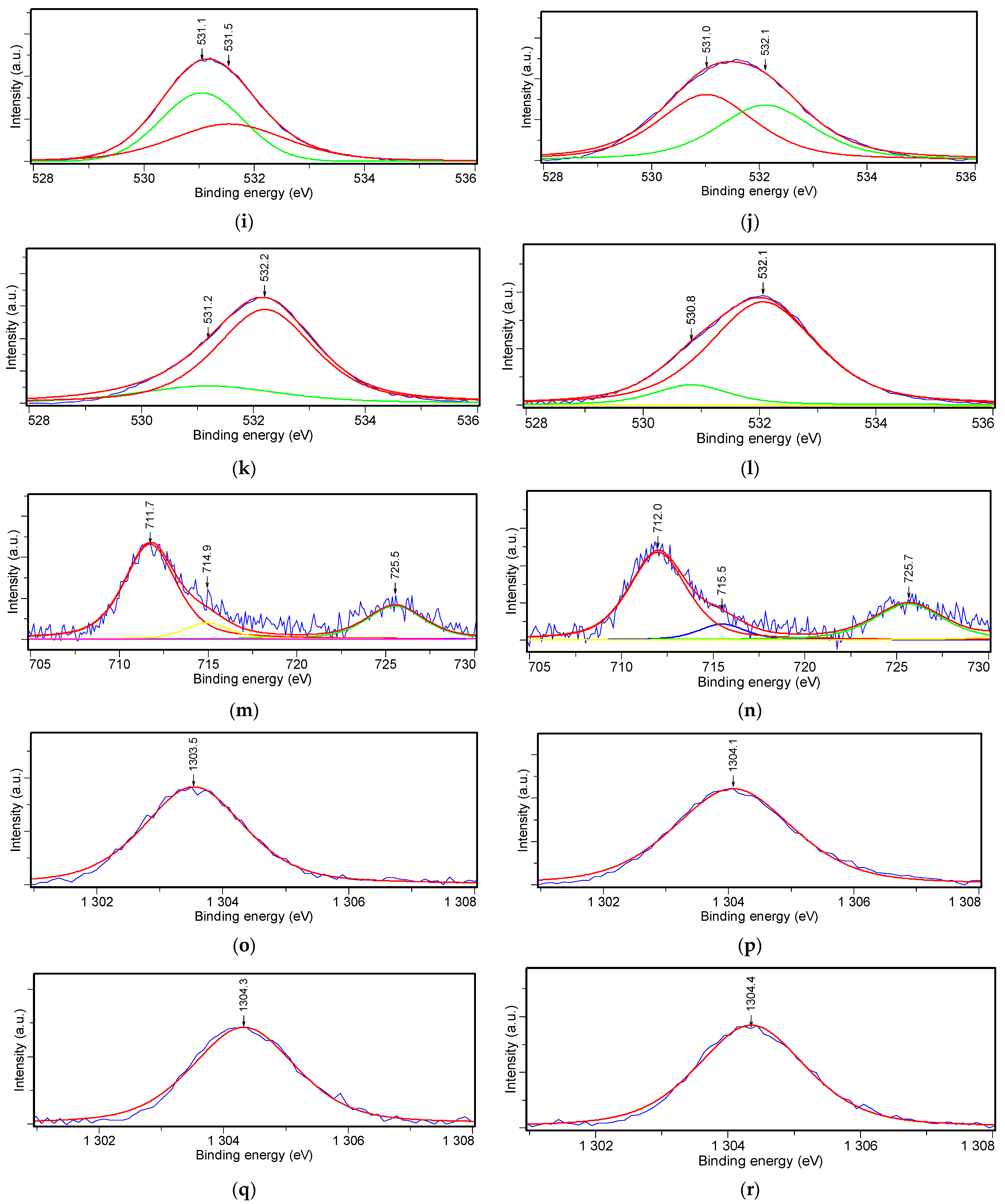
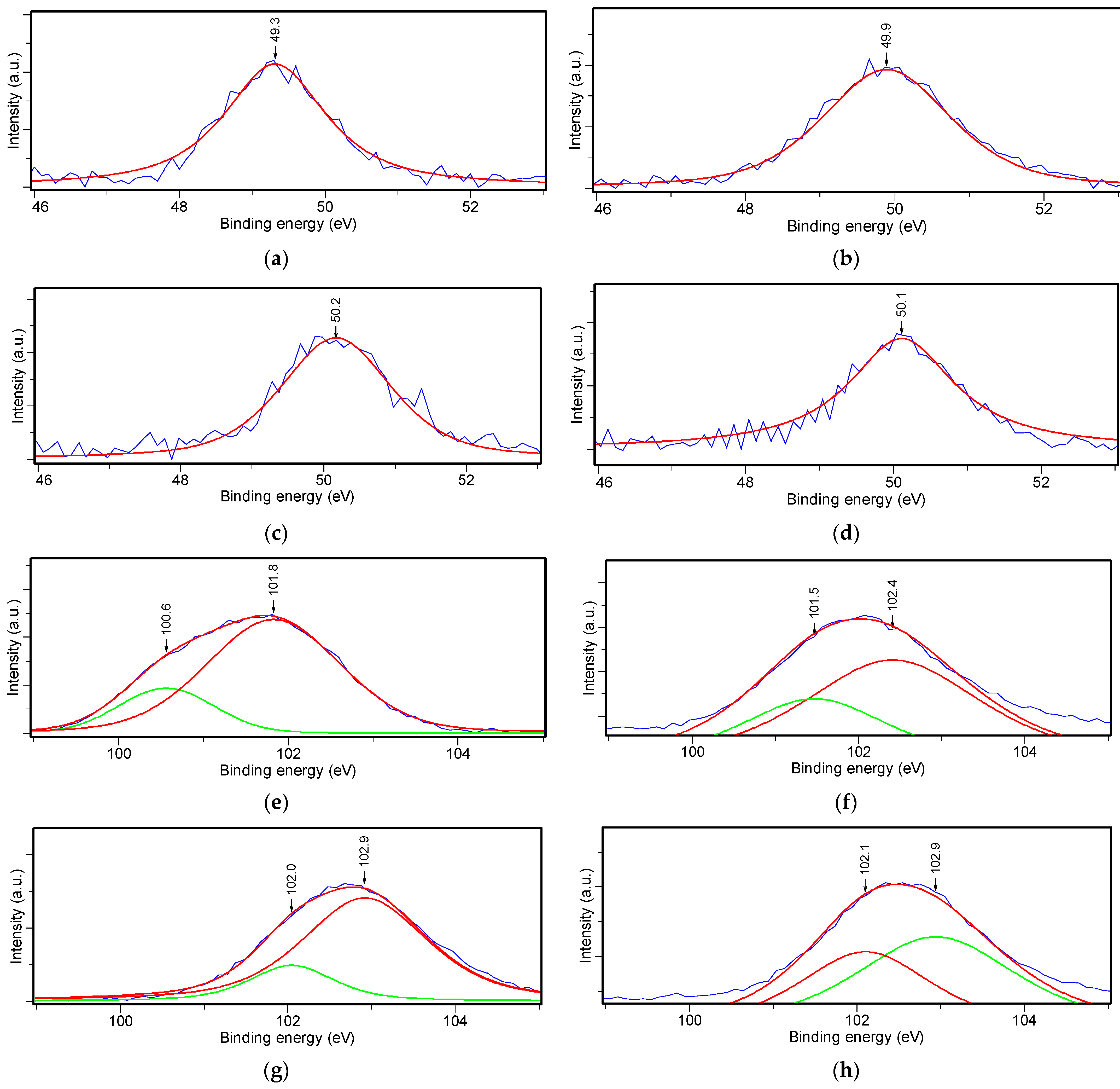
4.7. XPS Measurements

To assess the surface composition and chemical state of the specimens, XPS analysis was performed on the powders S1, S1FeSUB and S1FeXS. The outcomes were compared with a pure commercial sepiolite (Tolsa Pangel S9) (Figure 7). The photoelectron lines at a binding energy (BE) of 50.1, 102, 152.7, 531.7, 711.6 and 1304 eV correspond to Mg 2p, Si 2p, Si 2s, O 1s, Fe 2p and Mg 1s, respectively [44]. Table 4 shows the Mg 2p, Si 2p, Si 2s, O 1s, Fe 2p and Mg 1s BE values of the investigated powders.
It is well known that the chemical environment has an important effect on the binding energy value for a given core level measured by XPS. Any change in this chemical environment produces a shift in the core-level binding energy due to a spatial rearrangement of the valence charges and the creation of a different potential because of the nuclear and electronic charges on all of the other atoms in the compound. These shifts in binding energy are considered a fingerprint of the atom binding state, facilitating the detection of various compounds.
The deconvolution of the Mg 2p spectra (Figure 8a–d) was performed with a single component in the range 49–50 eV, attributed to Mg in the sepiolite structure [32]. The Si 2p spectra (Figure 8e–h) was deconvoluted with peaks at ≈101–102 eV and 102–103 eV. In the case of natural sepiolite, these peaks are due to Si in the Mg silicate framework, while these peaks can be attributed to silicates, as opposed to silica (binding energy of 103.6 eV) [32,44], in the synthetic sepiolite samples. The higher values of binding energies in synthetic sepiolite compared to the natural one could be an indication of the formation of a structure close to a molecular sieve [44]. The XPS O 1s spectra (Figure 8j–l)) were fitted with two components at binding energies of about 531 eV (lattice oxygen, O2−) and ca. 532.0 eV (hydroxyl groups, OH) [44,45]. The presence of hydrophilic groups (OH) is beneficial for the absorption of water molecules. The integration of the area under the deconvoluted peaks at about 532 eV indicated an increase in the number of hydroxyls in the S1 (1356.1 eV), S1FeSUB (2886.9 eV), and S1FeXS samples (3639.8 eV). In general, the Fe 2p spectrum consists of Fe 2p3/2 and 2p1/2 doublet peaks interspaced by 13.6 eV. The Fe 2p3/2 bands of the S1FeSUB and S1FeXS samples were fitted with three peaks at ≈712.0 eV, which is typical of Fe2+, at ≈715.0 eV, and finally at ≈725.5–725.7 eV (Figure 8m,n) [44,45,46]. The peak at 715 eV is a plasmon or satellite peak due to the main Fe 2p3/2 peak at 712 eV, and it is an indication of the presence of Fe2O3 [46]. Finally, the Mg 1s spectra (Figure 8o–r) were deconvoluted into a single component in the range from 1303.5−1304.4 eV. In synthetic powders, energy shifts to higher binding energy of ≈1 eV were observed for the peaks of Mg 1s, as well as for Mg 2p and Si 2p, compared to natural sepiolite, acting as further probable confirmation of the formation of magnesium silicate phases.

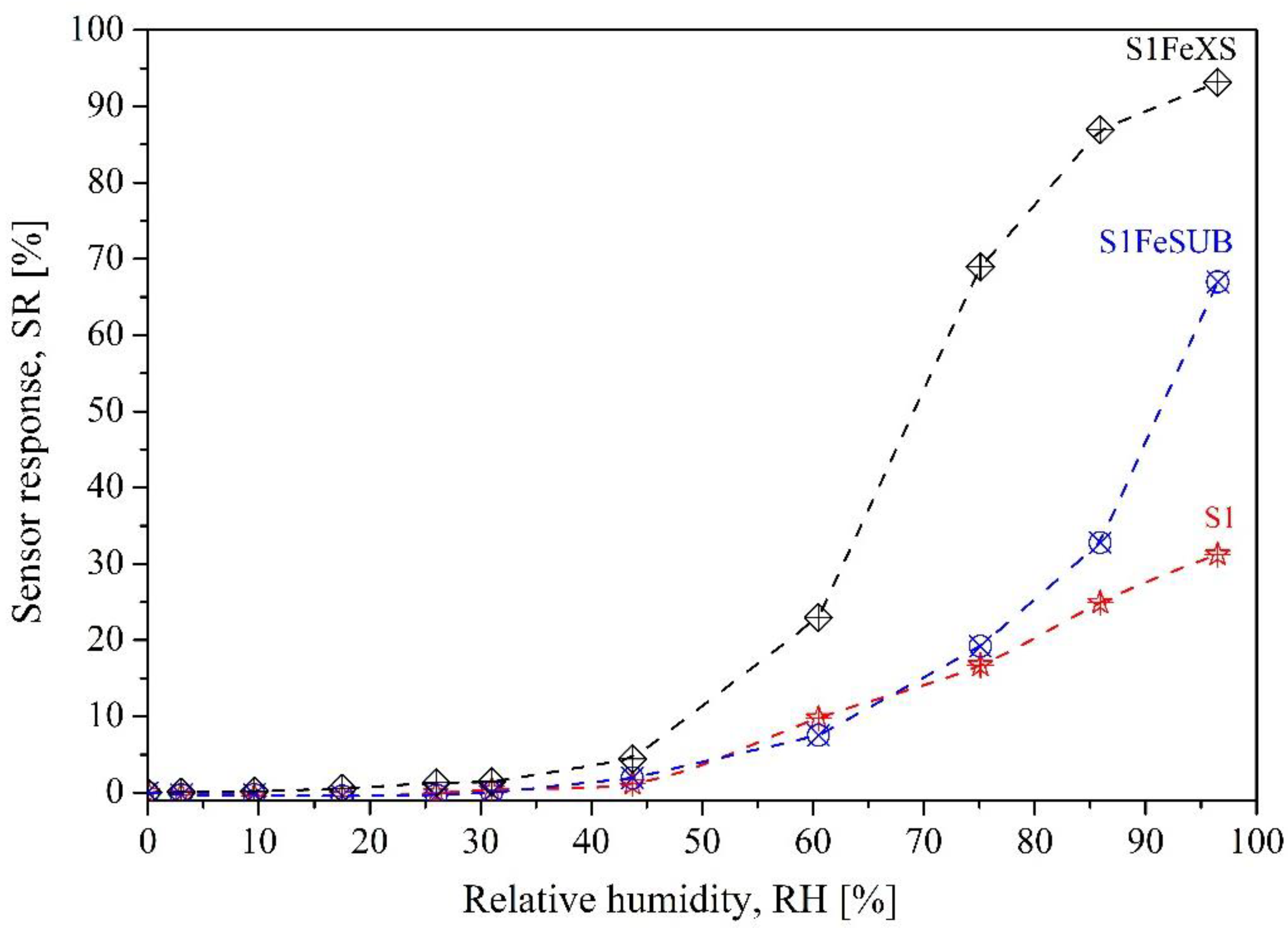
4.8. Sensitivity towards Humidity

The results obtained for the response of sensors to humidity are shown in Figure 9. According to these data, all investigated compositions presented a certain sensitivity to humidity from 30% RH. A slight response to humidity from about 18% RH was observed in the S1FeSUB and S1FeXS samples because of the presence of Fe2O3, as can be seen in the XRD patterns as well as the XPS and FTIR spectra. Fired sepiolite becomes hydrophobic because of the loss of the four water molecules coordinated to magnesium ions, as well as structure folding [28,36,37,38,39,40,41,42]. However, the presence of iron or tungsten ions restores its hydrophilicity [2,28].
In a previous work [2], the humidity sensing behavior of pure sepiolite heat treated at 520 °C for 15 min was investigated, and the resistance of the pellet decreased beyond 60% RH. The response of the S1 sensor was lower than that of the pellet based on natural sepiolite in [2] but started from 45% RH.
The higher response of the F1FeXS sensor compared to the S1 and S1FeSUB sensors is probably due to the higher amount of hydroxyl groups on its surface, as determined by integrating the area under the XPS peaks at about 532 eV.
The resistance value under air was around 4 MΩ, which is an important result, because values above 10 MΩ limit the practical use of resistive sensors [47].
Table 5 illustrates the response and recovery times of the sensors. It can be seen from these data that the response times reported for the S1FeXS sensor are shorter than those for the S1FeSUB sensor, which can be attributed to the easier accessibility of the hematite to water molecules. In addition, fast recovery times for both sensors show that physisorption is mostly involved when water molecules bind with the sensing materials. The possible reason for these results is that although sepiolite is a hydrophilic material, its ability to desorb water molecules is greater than its ability to adsorb them [48].
The Si–O bond is 50% ionic, because of the difference in the electronegativity value between oxygen and silicon atoms. Thus, silica is able to adsorb polar molecules like water [49]. In addition, α-Fe2O3 is a known n-type semiconductor. The presence of pores favors a conduction mechanism based on the chemical and physical adsorption of water molecules on the surface, as well as from the capillary condensation of water inside the pores of the materials [50]. The conduction mechanism occurs in several different consecutive steps. First, water molecules are ionized in OH and H+. Then, the hydroxyl ions are chemisorbed on lattice iron, while H+ ions form hydroxyl groups with double ionized oxygens displaced from the lattice [51]. This chemisorbed water layer then adsorbs other water molecules thanks to hydrogen bonding. At low RH values, a discontinuous film of water molecules is formed on this chemisorbed layer. At this stage of water vapor adsorption, protons cannot hop, because there is no continuous path. However, above 30% RH, physisorbed layers begin to be formed [47]. With increasing relative humidity, in addition to adsorption processes, the capillary condensation of water vapor occurs in porous materials, which is in agreement with the Kelvin’s equation [5]. Water condensation produces a strong drop in the sensors’ impedance values. Finally, when multi-layer continuous water molecules are formed, a high charge density is present at the surface of the sensing film, which dissociates the physisorbed water molecules, producing hydronium ions (H3O+) [5]. Proton hopping transport takes place when an electrostatic field is applied to the sensor and is responsible for conduction at up to 70% RH [47]. All these factors can explain the sudden decrease in resistance observed with increasing RH.
Table 6 compares the performances of the proposed sensor with literature data. These are in any case interesting, considering that the sensor is a planar one and not a pellet one, as is the case of many of the cited works; its resistance under air is not too high for practical use (about 4 MΩ); and there is reasonable adhesion of the sensing film to the substrate due to the thermal treatment.
Finally, the sensors S1FeSUB and S1FeXS were also investigated with respect to gases that can create possible interference, such as CO2 (500 ppm), NH3 (500 ppm) and CH4 (1000 ppm). Their responses (not shown here) were below 1.5%, and thus these sensors can be considered insensitive to these gases and selective with respect to water vapor.

5. Conclusions

In summary, an iron-doped magnesium silicate nanopowder was successfully synthesized using a simple and low-cost sol–gel method. The sensing material employing 10 wt% Fe3+ ions exhibited better results than those obtained for the stoichiometric synthetic sepiolite: the sensor S1FeXS was able to detect water vapor from about 18% RH with reasonable response and recovery times (some minutes). In addition, its resistance value under air was not too high for practical use (about 4 MΩ).
Finally, no response was observed in the presence of interfering gases such as CO2 (500 ppm), NH3 (500 ppm) and CH4 (1000 ppm). Nevertheless, the composition of specimens should be optimized to detect lower humidity values (below 18% RH).

Author Contributions

Conceptualization, A.S.A. and J.-M.T.; methodology, A.S.A. and J.-M.T.; validation, A.S.A. and J.-M.T.; formal analysis, A.S.A. and J.-M.T.; investigation, A.S.A. and J.-M.T.; resources, J.-M.T.; data curation, A.S.A., M.D. and J.-M.T.; writing—original draft preparation, A.S.A., M.D. and J.-M.T.; writing—review and editing, A.S.A., M.D. and J.-M.T.; supervision, J.-M.T. All authors have read and agreed to the published version of the manuscript.

Funding

This research received no external funding.

Institutional Review Board Statement

Not applicable.

Informed Consent Statement

Not applicable.

Data Availability Statement

Not applicable.

Conflicts of Interest

The authors declare no conflict of interest.

References

  1. Barmpakos, D.; Kaltsas, G. A Review on Humidity, Temperature and Strain Printed Sensors—Current Trends and Future Perspectives. Sensors 2021, 21, 739. [Google Scholar] [CrossRef]
  2. Esteban-Cubillo, A.; Tulliani, J.-M.; Pecharromán, C.; Moya, J.S. Iron-oxide nanoparticles supported on sepiolite as a novel humidity sensor. J. Eur. Ceram. Soc. 2007, 27, 1983–1989. [Google Scholar] [CrossRef]
  3. Céline Laville, C.P.; Deletage, J.-Y. Humidity sensors for a pulmonary function diagnostic microsystem. Sens. Actuators B Chem. 2001, 76, 304–309. [Google Scholar] [CrossRef]
  4. Tulliani, J.-M.; Baroni, C.; Zavattaro, L.; Grignani, C. Strontium-Doped Hematite as a Possible Humidity Sensing Material for Soil Water Content Determination. Sensors 2013, 13, 12070–12092. [Google Scholar] [CrossRef] [PubMed]
  5. Traversa, E. Ceramic sensors for humidity detection: The state-of-the-art and future developments. Sens. Actuators B Chem. 1995, 23, 135–156. [Google Scholar] [CrossRef]
  6. Chen, Z.; Lu, C. Humidity Sensors: A Review of Materials and Mechanisms. Sens. Lett. 2005, 3, 274–295. [Google Scholar] [CrossRef]
  7. Lukaszewicz, J.P. Carbon-film-based humidity sensor containing sodium or potassium. Recovery effect. Sens. Actuators B Chem. 1999, 60, 184–190. [Google Scholar] [CrossRef]
  8. Varghese, O.K.; Kichambre, P.D.; Gong, D.; Ong, K.G.; Dickey, E.C.; Grimes, C.A. Gas sensing characteristics of multi-wall carbon nanotubes. Sens Actuators B Chem. 2001, 81, 32–41. [Google Scholar] [CrossRef]
  9. Yao, Y.; Chen, X.; Guo, H.; Wu, Z. Graphene oxide thin film coated quartz crystal microbalance for humidity detection. Appl. Surf. Sci. 2011, 257, 7778–7782. [Google Scholar] [CrossRef]
  10. Chu, J.; Peng, X.; Feng, P.; Sheng, V.; Zhang, J. Study of humidity sensors based on nanostructured carbon films produced by physical vapor deposition. Sens. Actuators B Chem. 2013, 178, 508–513. [Google Scholar] [CrossRef]
  11. Phan, D.-T.; Chung, G.-S. Effects of rapid thermal annealing on humidity sensor based on graphene oxide thin films. Sens. Actuators B Chem. 2015, 220, 1050–1055. [Google Scholar] [CrossRef]
  12. Tulliani, J.-M.; Inserra, B.; Ziegler, D. Carbon-Based Materials for Humidity Sensing: A Short Review. Micromachines 2019, 10, 232. [Google Scholar] [CrossRef] [PubMed]
  13. Afify, A.S.; Ahmad, S.; Khushnood, R.A.; Jagdale, P.; Tulliani, J.-M. Elaboration and characterization of novel humidity sensor based on micro-carbonized bamboo particles. Sens. Actuators B Chem. 2017, 239, 1251–1256. [Google Scholar] [CrossRef]
  14. Ziegler, D.; Palmero, P.; Giorcelli, M.; Tagliaferro, A.; Tulliani, J.-M. Biochars as Innovative Humidity Sensing Materials. Chemosensors 2017, 5, 35. [Google Scholar] [CrossRef]
  15. Konta, J. Clay and man: Clay raw materials in the service of man. Appl. Clay Sci. 1995, 4, 269–335. [Google Scholar] [CrossRef]
  16. Murray, H.H. Traditional and new applications for kaolin, smectite, and palygorskite: A general overview. Appl. Clay Sci. 2000, 17, 207–221. [Google Scholar] [CrossRef]
  17. Choy, J.-H.; Choi, S.-J.; Oh, J.-M.; Park, T. Clay minerals and layered double hydroxides for novel biological applications. Appl. Clay Sci. 2007, 36, 122–132. [Google Scholar] [CrossRef]
  18. Zhou, C.; Li, X.; Ge, Z.; Li, Q. Synthesis and acid catalysis of nanoporous silica/alumina-clay composites. Catal. Today 2004, 93, 607–613. [Google Scholar] [CrossRef]
  19. Adoor, S.G.; Sairam, M.; Manjeshwar, L.S.; Raju, K.V.S.N.; Aminabhavi, T.M. Sodium montmorillonite clay loaded novel mixed matrix membranes of poly (vinyl alcohol) for pervaporation dehydration of aqueous mixtures of isopropanol and 1,4-dioxane. J. Memb. Sci. 2006, 285, 182–195. [Google Scholar] [CrossRef]
  20. Afify, A.S.; Hassan, M.; Piumetti, M.; Peter, I.; Bonelli, B.; Tulliani, J.-M. Elaboration and characterization of modified sepiolites and their humidity sensing features for environmental monitoring. Appl. Clay Sci. 2015, 115, 165–173. [Google Scholar] [CrossRef]
  21. Mar González del Campo, M.; Darder, M.; Aranda, P.; Akkari, M.; Huttel, Y.; Mayoral, A.; Bettini, J.; Ruiz-Hitzky, E. Functional Hybrid Nanopaper by Assembling Nanofibers of Cellulose and Sepiolite. Adv. Funct. Mater. 2018, 28, 1703048. [Google Scholar] [CrossRef]
  22. Ma, Y.; Zhang, G. Sepiolite nanofiber-supported platinum nanoparticle catalysts toward the catalytic oxidation of formaldehyde at ambient temperature: Efficient and stable performance and mechanism. Chem. Eng. J. 2016, 288, 70–78. [Google Scholar] [CrossRef]
  23. Deng, C.; Jiang, Y.; Fan, Z.; Zhao, S.; Ouyang, D.; Tan, J.; Zhang, P.; Ding, Y. Sepiolite-based separator for advanced Li-ion batteries. Appl. Surf. Sci. 2019, 484, 446–452. [Google Scholar] [CrossRef]
  24. Zhang, J.; Yan, Z.; Ouyang, J.; Yang, H.; Chen, D. Highly dispersed sepiolite-based organic modified nanofibers for enhanced adsorption of Congo red. Appl. Clay Sci. 2018, 157, 76–85. [Google Scholar] [CrossRef]
  25. Wollast, R.; Mackenzie, F.T.; Bricker, O.P. Experimental precipitation and genesis of sepiolite at Earth-surface conditions. Am. Mineral. 1968, 53, 1645–1662. [Google Scholar]
  26. del Río, M.S.; García-Romero, E.; Suárez, M.; da Silva, I.; Fuentes-Montero, L.; Martínez-Criado, G. Variability in sepiolite: Diffraction studies. Am. Mineral. 2011, 96, 1443–1454. [Google Scholar] [CrossRef]
  27. Hibino, T.; Tsunashima, A.; Yamazaki, A.; Otsuka, R. Model Calculation of Sepiolite Surface Areas. Clay Clay Miner. 1995, 43, 391–396. [Google Scholar] [CrossRef]
  28. Hassan, M.; Afify, A.S.; Tulliani, J.-M. Synthesis of ZnO Nanoparticles onto Sepiolite Needles and Determination of Their Sensitivity toward Humidity, NO2 and H2. J. Mater. Sci. Technol. 2016, 32, 573–582. [Google Scholar] [CrossRef]
  29. Mizutani, T.; Fukushima, Y.; Okada, A.; Kamigaito, O.; Kobayashi, T. Synthesis of 1:1 and 2:1 iron phyllosilicates and characterization of their iron state by mössbauer spectroscopy. Clay Min. 1991, 39, 381–386. [Google Scholar] [CrossRef]
  30. Narasimharao, K.; Mokhtar, M.; Basahel, S.N.; Al-Thabaiti, S.A. Synthesis, characterization, and catalytic activity of nitridated magnesium silicate catalyst. J. Mater. Sci. 2013, 48, 4274–4283. [Google Scholar] [CrossRef]
  31. Tulliani, J.-M.; Bonville, P. Influence of the dopants on the electrical resistance of hematite-based humidity sensors. Ceram. Int. 2005, 31, 507–514. [Google Scholar] [CrossRef]
  32. Walczyka, A.; Michalik, A.; Napruszewska, B.D.; Kryściak-Czerwenka, J.; Karcza, R.; Duraczyńska, D.; Socha, R.P.; Olejniczak, Z.; Gaweł, A.; Klimek, A.; et al. New insight into the phase transformation of sepiolite upon alkali activation: Impact on composition, structure, texture, and catalytic/sorptive properties. Appl. Clay Sci. 2020, 195, 105740. [Google Scholar] [CrossRef]
  33. Shuali, U.; Bram, L.; Steinberg, M.; Yariv, S. Infrared study of the thermal treatment of sepiolite and palygorskite saturated with organic amines. Thermochim. Acta 1989, 148, 445–456. [Google Scholar] [CrossRef]
  34. Vicente Rodríguez, M.A.; López-González, J.D.D.; Bañares-Muñoz, M.A. Influence of the free silica generated during acid activation of a sepiolite on the adsorbent and textural properties of the resulting solids. J. Mater. Chem. 1995, 5, 127–132. [Google Scholar] [CrossRef]
  35. Dutt, M.; Suhasini, K.; Ratan, A.; Shah, J.; Kotnala, R.K.; Singh, V. Mesoporous silica mediated synthesis of α-Fe2O3 porous structures and their application as humidity sensors. J. Mater. Sci. Mater. El. 2018, 29, 20506–20516. [Google Scholar] [CrossRef]
  36. Miura, A.; Nakazawa, K.; Takei, T.; Kumada, N.; Kinomura, N.; Ohki, R.; Koshiyama, H. Acid-, base-, and heat-induced degradation behavior of Chinese sepiolite. Ceram. Int. 2012, 38, 4677–4684. [Google Scholar] [CrossRef]
  37. Nagata, H.; Shimoda, S.; Sudo, T. On Dehydration of Bound Water of Sepiolite. Clay Clay Miner. 1974, 22, 285–293. [Google Scholar] [CrossRef]
  38. Serna, C.; Ahrlichs, J.L.; Serratosa, J.M. Folding in Sepiolite Crystals. Clay Cla. Miner. 1975, 23, 452–457. [Google Scholar] [CrossRef]
  39. Torró-Palau, A.; Fernández-García, J.C.; Orgilés-Barceló, A.C. Structural modification of sepiolite (natural magnesium silicate) by thermal treatment: Effect on the properties of polyurethane adhesives. Int. J. Adhes. Adhes. 1997, 17, 111–119. [Google Scholar] [CrossRef]
  40. Molina-Sabio, M.; Caturla, F.; Rodríguez-Reinoso, F.; Kharitonova, G.V. Porous structure of a sepiolite as deduced from the adsorption of N2, CO2, NH3 and H2O. Microporous Mesoporous Mater. 2001, 47, 389–396. [Google Scholar] [CrossRef]
  41. Kok, M.V. Thermal Characterization of Sepiolite Samples. Energy Sources Part A 2013, 35, 173–183. [Google Scholar] [CrossRef]
  42. Valentin, J.L.; López-Manchado, M.A.; Rodríguez, A.; Posadas, P.; Ibarra, L. Novel anhydrous unfolded structure by heating of acid-pretreated sepiolite. Appl. Clay Sci. 2007, 36, 245–255. [Google Scholar] [CrossRef]
  43. Khan, I.; Morishita, S.; Higashinaka, R.; Matsuda, T.D.; Aoki, Y.; Kuzmann, E.; Homonnay, Z.; Katalin, S.; Pavić, L.; Kubuki, S. Synthesis, characterization and magnetic properties of ε-Fe2O3 nanoparticles prepared by sol-gel method. J. Magn. Magn. Mater. 2021, 538, 168264. [Google Scholar] [CrossRef]
  44. Moulder, J.F.; Stickle, W.F.; Sobol, P.E.; Bomben, K.D. Handbook of X-ray Photoelectron Spectroscopy; Perkin Elmer Corporation Publisher: Waltham, MA, USA, 1992. [Google Scholar]
  45. Habish, A.M.; Lazarević, S.; Janković-Častvan, I.; Jokić, B.; Kovač, J.; Rogan, J.; Janaćković, Đ.; Petrović, R. Nanoscale zerovalent iron (nZVI) supported by natural and acid-activated sepiolites: The effect of the nZVI/support ratio on the composite properties and Cd2+ adsorption. Environ. Sci. Pollut. Res. 2017, 24, 628–643. [Google Scholar] [CrossRef]
  46. Yamashita, T.; Hayes, P. Analysis of XPS spectra of Fe2+ and Fe3+ ions in oxide material. Appl. Surf. Sci. 2008, 254, 2441–2449. [Google Scholar] [CrossRef]
  47. Neri, G.; Bonavita, A.; Galvagno, S.; Pace, C.; Patanè, S.; Arena, A. Humidity sensing properties of Li–iron oxide based thin films. Sens. Actuators B Chem. 2001, 73, 89–94. [Google Scholar] [CrossRef]
  48. Duan, Z.; Jiang, Y.; Zhao, Q.; Wang, S.; Yuan, Z.; Zhang, Y.; Liu, B.; Tai, H. Facile and low-cost fabrication of a humidity sensor using naturally available sepiolite nanofibers. Nanotechnology 2020, 31, 355501. [Google Scholar] [CrossRef]
  49. Ahmaruzzaman, M.; Gupta, V. Rice husk and its ash as low-cost adsorbents in water and wastewater treatment. Ind. Eng. Chem. Res. 2011, 50, 13589–13613. [Google Scholar] [CrossRef]
  50. Seiyama, T.; Yamazoe, N.; Arai, H. Ceramic humidity sensors. Sens. Actuators 1983, 4, 86–96. [Google Scholar] [CrossRef]
  51. Yuan, Q.; Li, N.; Geng, W.; Chi, Y.; Tu, J.; Li, X.; Shao, C. Humidity sensing properties of mesoporous iron oxide/silica composite prepared via hydrothermal process. Sens. Actuators B Chem. 2011, 160, 334–340. [Google Scholar] [CrossRef]
  52. Pelino, M.; Colella, C.; Cantalini, C.; Faccio, M.; Ferri, G.; D’Amico, A. Microstructure and electrical properties of an a-hematite ceramic humidity sensor. Sens. Actuators B Chem. 1992, 7, 464–469. [Google Scholar] [CrossRef]
  53. Cantalini, C.; Faccio, M.; Ferri, G.; Pelino, M. Microstructure and electrical properties of Si-doped α-Fe2O3 humidity sensor. Sens. Actuators B Chem. 1993, 15, 293–298. [Google Scholar] [CrossRef]
  54. Chauhan, P.; Annapoorni, S.; Trikha, S.K. Humidity-sensing properties of nanocrystalline haematite thin films prepared by sol-gel processing. Thin Solid Films 1999, 346, 266–268. [Google Scholar] [CrossRef]
  55. Tandon, R.P.; Tripathy, M.R.; Arora, A.K.; Hotchandani, S. Gas and humidity response of iron oxide—Polypyrrole nanocomposites. Sens. Actuators B Chem. 2006, 114, 768–773. [Google Scholar] [CrossRef]
  56. Khalil, K.M.S.; Makhlouf, S.A. Humidity sensing properties of porous iron oxide/silica nanocomposite prepared via a formamide modified sol–gel process. Sens. Actuators A Phys. 2008, 148, 39–43. [Google Scholar] [CrossRef]
  57. Nica, S.-L.; Nica, V.; Grigoras, V.C.; Varganici, C.-D.; Popovici, D.; Hulubei, C.; Ioan, S. Influence of two structural phases of Fe3O4 and γ-Fe2O3 on the properties of polyimide/iron oxide composites. Polym. Int. 2015, 64, 1172–1181. [Google Scholar] [CrossRef]
  58. Songkeaw, P.; Onlaor, K.; Tunhoo, B. A humidity sensor based on iron oxide films prepared by spin coating process. Mater. Today Proc. 2017, 4, 6512–6518. [Google Scholar] [CrossRef]
  59. Yadav, B.C.; Chauhan, K.S.; Singh, S.; Sonker, R.K.; Sikarwar, S.; Kumar, R. Growth and characterization of sol–gel processed rectangular shaped nanostructured ferric oxide thin film followed by humidity and gas sensing. J. Mater. Sci. Mater. Electron. 2017, 28, 5270–5280. [Google Scholar] [CrossRef]
  60. Hashim, A.; Agool, I.R.; Kadhim, K.J. Novel of (polymer blend-Fe3O4) magnetic nanocomposites: Preparation and characterization for thermal energy storage and release, gamma ray shielding, antibacterial activity and humidity sensors applications. J. Mater. Sci. Mater. Electron. 2018, 29, 10369–10394. [Google Scholar] [CrossRef]
  61. Ahmad, W.R.W.; Mamat, M.H.; Zoolfakar, A.S.; Khusaimi, Z.; Yusoff, M.M.; Ismail, A.S.; Roslan, S.S.; Rusop, M. The performance of humidity sensors using iron oxide as the sensor element. In Proceedings of the 8th IEEE International Conference on Control System, Computing and Engineering (ICCSCE 2018), Penang, Malaysia, 23–25 November 2018; pp. 217–222. [Google Scholar]
  62. Khorsand Zak, A.; Shirmahd, H.; Mohammadi, S.; Banishemian, S.M. Solvothermal synthesis of porous Fe3O4 nanoparticles for humidity sensor application. Mater. Res. Express 2020, 7, 025001. [Google Scholar] [CrossRef]
  63. Umair Khan, M.; Hassan, G.; Awais, M.; Bae, J. All printed full range humidity sensor based on Fe2O3. Sens. Actuators A Phys. 2020, 311, 112072. [Google Scholar] [CrossRef]
  64. Manikandan, V.; Mirzaei, A.; Petrila, I.; Kavita, S.; Mane, R.S.; Denardin, J.C.; Lundgaard, S.; Juodkazis, S.; Chandrasekaran, J.; Vigneselvan, S. Effect of neodymium stimulation on the dielectric, magnetic and humidity sensing properties of iron oxide nanoparticles. Mater. Chem. Phys. 2020, 254, 123572. [Google Scholar] [CrossRef]
  65. Tippo, P.; Singjai, P.; Sroila, W.; Jaisamer, T.; Suttanon, N.; Panthawan, A.; Kantarak, E.; Sroila, W.; Thongsuwan, W.; Kumpika, T.; et al. Improving the properties of Fe2O3 by a sparking method under a uniform magnetic field for a high-performance humidity sensor. RSC Adv. 2022, 12, 1527–1533. [Google Scholar] [CrossRef]
Figure 1. Preparation steps of sensing film, (a) Al2O3 substrate, (b) Al2O3 substrate with IDEs, (c) sensing film over screen-printed IDEs (scale bar in mm; sensing material printed area: ca. 31 mm2).
Ceramics 05 00043 g001
Figure 2. XRD patterns of the S1, S1FeSUB and S1FeXS powders after calcination at 500 °C for 2 h.
Ceramics 05 00043 g002
Figure 3. FTIR spectra of powders S1 and S1FeSUB after calcination at 500 °C.
Ceramics 05 00043 g003
Figure 4. TG–DTA curves of powder: S1 (a) and S1FeSUB (b) (endothermic peaks are upward).
Ceramics 05 00043 g004
Figure 5. FESEM micrographs of: S1 powder after calcination at 500 °C for 5 h (a,b); screen-printed S1 sensor at various magnifications, after calcination at 550 °C for 1 h (cf).
Ceramics 05 00043 g005
Figure 6. FESEM micrographs of: sol S1FESUB after drying in the oven (a,b); screen-printed films S1FeSUB (c,e) and S1FeXS (d,f), at various magnifications, after calcination at 550 °C for 1 h.
Ceramics 05 00043 g006
Figure 7. XPS survey spectra of natural sepiolite (Tolsa Pangel S9), S1, S1FeSUB and S1FeXS powders.
Ceramics 05 00043 g007
Figure 8. XPS high-resolution spectra of powders: natural sepiolite (a), S1 (b), S1FeSUB (c) and S1FeXS (d) (Mg 2p lines); natural sepiolite (e), S1 (f), S1FeSUB (g) and S1FeXS (h) (Si 2p lines); natural sepiolite (i), S1 (j), S1FeSUB (k) and S1FeXS (l) (O 1s lines); S1FeSUB (m) and S1FeXS (n) (Fe 2p lines); natural sepiolite (o), S1 (p), S1FeSUB (q) and S1FeXS (r) (Mg 1s lines) (the blue line is the experimental curve, while the different colored lines are due to the deconvolution of the different peaks; the top red line is the sum of the overall deconvoluted peaks).
Ceramics 05 00043 g008aCeramics 05 00043 g008b
Figure 9. Sensors’ response to humidity at ambient temperature.
Ceramics 05 00043 g009
Table 1. Particle size distribution of S1, S1FeSUB and S1FeXS powders after calcination at 500 °C.
Cumulative vol%S1 SampleS1FeSUB SampleS1FeXS Sample
108.55.13.9
5088.526.418.5
90140.0111.498.5
Table 2. Detail of FTIR band assignment for the S1 and S1FeSUB samples.
AssignmentWavenumber (cm−1)
S1S1FeSUB
Mg3OH unit stretching and
hydroxyl translation and bending mode
3686.1, 672.13686.1, 675.6
OH stretching vibrations in H2O molecules
coordinated to Mg at the ribbon edges
3623.9, 3567.23623.9, 3567.2
H2Ozeolitic3448.43442.8, 1718.7, 1655.8
C–H-O-CH32930.32930.3
H2Ocoordinated1633.41633.4
Fe–OH vibration---1471.2, 1378.9
Si–O–Si asymmetric stretching1206.91206.9
Si–O in-plane stretching1035.61035.6
O–Si–O and/or Si–O–Si bending797.2797.2
Perpendicular Mg–OH vibration563.7---
Deformation mode of MgO6 octahedral units454.6453.9
Table 3. Specific surface area of the S1 and S1FeSUB sample powders after calcination for 5 h at 500 °C.
SampleSSA (m2/g)Porosity (cm3/g)Pore Size (nm)
S1151.30.318.1
S1FeSUB81.30.209.4
Table 4. Binding energy (in eV) of electrons in the internal levels for natural sepiolite and the prepared synthetic samples.
SampleMg 2pSi 2pO 1sFe 2pMg 1s
Natural sepiolite49.3100.6, 101.8531.1, 531.5---1303.5
S149.9101.5, 102.4531.0, 532.1---1304.1
S1FeSUB50.2102.0, 102.9531.2, 532.2711.7, 714.9, 725.51304.3
S1FeXS50.1102.1, 102.9530.8, 532.1712.0, 715.5, 725.71304.4
Table 5. Response time and recovery time for the S1FeSUB and S1FeXS sensors.
SampleResponse Time (min)Recovery Time (min)
From 0% to 60% RHFrom 0% to 90% RHFrom 60% to 0% RHFrom 90% RH to 0% RH
S1FeSUB5.15.31.61.5
S1FeXS2.84.90.82
Table 6. Comparison of the synthetic sepiolite sensor’s performance with literature data regarding sensors based on sepiolite and iron oxide operating at room temperature (unless specified).
Sensing Material Sensor Response
(Rair/Rhumid Unless Specified)
Response TimeRecovery TimeReference
Pressed α-Fe2O3/sepiolite prepared by a wet chemical route36.2 under 80% RH3 min when RH changed from 0% to 80%n.d.[2]
Pressed W4+-doped sepiolite prepared by a wet chemical route≈98% relative change of resistance under 90% RH18.1 min when RH changed from 0% to 90%1.5 min when RH changed from 0% to 90%[13]
Pure sepiolite painted on alumina substrate with IDEs528 under 91.5% RH26 s when RH changed from 10.9% to 91.5%17 s when RH changed from 91.5% to 10.9%[48]
Pressed α-Fe2O3≈660 under 95% RHn.d.n.d.[52]
Pressed 2% Si-doped α-Fe2O3≈1300 under 95% RH≈6 min when RH changed from 0% to 60%≈3 min when RH changed from 60% to 0%[53]
α-Fe2O3 thin film made by spin casting≈300 under 85% RHn.d.n.d.[54]
20 mol% Li-doped α-Fe2O3 thin film made by drop coating≈830 under 90% RH
(Ratio of the capacitance value under humidity by the capacitance under 10% RH)
n.d.n.d.[47]
Screen-printed 5%SrO-doped Fe2O3 filmAbout 3 orders of magnitude change in resistance in the range 0%–100% RHn.d.n.d.[31]
Pressed 27% polypyrrole–Fe3O4 synthesized by an emulsion polymerization in water980 under 80% RHn.d.n.d.[55]
Pressed Fe2O3/SiO2 nanocomposites made by sol–gelAbout 3 orders of magnitude change in conductivity in the range 15%–100% RHn.d.n.d.[56]
Screen-printed 1:1 Fe2O3/SiO2 composites via hydrothermal route10,000 under 95% RH20 s when RH changed from 11% to 95%40 s when RH changed from 95% to 11%[51]
Cast films of polyimide/20% Fe2O3 or Fe3O4 composites≈90% relative change of resistance under 100% RHn.d.n.d.[57]
Spin-coated Fe2O3 films≈260 under 93% RH<50 s when RH changed from 23% to 93%<50 s when RH changed from 93% to 23%[58]
Spin-coated sol–gel Fe2O3 filmsAbout 2 orders of magnitude change in resistance in the range 10%–90% RHn.d.n.d.[59]
Polyvinyl alcohol-polyethylene glycol- Polyvinylpyrrolidone-Fe3O4 filmsAbout 2 orders of magnitude change in resistance in the range 40%–90% RHn.d.n.d.[60]
Mesoporous α-Fe2O3 on silica gel≈1000 under 93% RH60 s when RH changed from 11% to 93%140 s when RH changed from 93% to 11%[35]
Solution synthesis of α-Fe2O3 films30.68 under 90% RHn.d.n.d.[61]
Spin coating of solvothermal synthesized Fe3O4-polyvinylpyrrolidone≈35% relative change of resistance under 70% RHn.d.n.d.[62]
Spin-coated Fe2O3 films≈18.8 under 96.5% RH1.79 s when RH changed from 0% to 100%4.97 s when RH changed from 100% to 0%[63]
Pressed co-precipitated Nd–Fe2O3 85% relative change of resistance under 100% RH5 s when RH changed from 0% to 80%88 s when RH changed from 80% to 0%[64]
Fe2O3 thin film deposited under magnetic fieldAbout 6 orders of magnitude change in resistance in the range 10%–100% RH at 95 °C0.33 s when RH changed from 0% to 100% at 95 °C2.57 s when RH changed from 100% to 0% at 95 °C[65]
Screen-printed sol–gel-synthesized Fe2O3-doped synthetic sepiolite≈14.7 under 96.5% RH4.9 min, when RH changed from 0% to 90%2 min, when RH changed from 90% to 0%This work
n.d.: not determined.
Publisher’s Note: MDPI stays neutral with regard to jurisdictional claims in published maps and institutional affiliations.

