Article

Manufacturing and Thermal Shock Characterization of Porous Yttria Stabilized Zirconia for Hydrogen Energy Systems

by
M. Faisal Riyad
,
Mohammadreza Mahmoudi
and
Majid Minary-Jolandan
*
Mechanical and Aerospace Engineering, School for Engineering of Matter, Transport and Energy, Arizona State University, Tempe, AZ 85287, USA
*
Author to whom correspondence should be addressed.
Ceramics 2022, 5(3), 472-483; https://doi.org/10.3390/ceramics5030036
Submission received: 25 July 2022 / Revised: 17 August 2022 / Accepted: 18 August 2022 / Published: 22 August 2022
(This article belongs to the Special Issue Ceramics for Decarbonization of the Global Industry)

Abstract

:
Porous yttriastabilized zirconia (YSZ), in a composite with NiO, is widely used as a cermet electrode in solid oxide fuel cells (SOFCs) and solid oxide electrolysis cells (SOECs). Given cycles of high temperature in these energy devices, mechanical integrity of the porous YSZ is critical. Pore morphology, as well as properties of the ceramic, ultimately affect the mechanical properties of the cermet electrode. Here, we fabricated porous YSZ sheets via freezing of an aqueous slurry on a cold thermoelectric plate and quantified their flexural properties, both for as-fabricated samples and samples subjected to thermal shock at 200 °C to 500 °C. Results of this work have implications for the hydrogen economy and global decarbonization efforts, in particular for the manufacturing of SOFCs and SOECs.

1. Introduction

Porous ceramics are used in energy and environment applications for energy storage and conversion devices (batteries, fuel cells, and concentrated solar power), catalyst support (for environmental remediation, hydrogenation processes and carbon capture), filters (such as hot-gas filters, diesel particulate filters, and water filtration systems), insulators, energy harvesting devices (piezoelectric ceramics), and electromagnetic wave shielding [1,2,3]. They are also attractive for bio-scaffolds for tissue engineering. In terms of structural applications, they are desirable as infiltration preforms for manufacturing of composites [4]. Low density, large specific surface area, high toughness, thermal shock resistance, good thermal insulation capability, excellent high temperature stability, and a low dielectric constant are among the attractive properties of porous ceramics [1]. In porous ceramics, the pore structure (size, configuration, and geometry) is largely determined by processing and manufacturing. The pore structure, in turn, affects their properties (both structural and functional).
Crack-pore interaction in porous ceramics may enhance their damage tolerance and thermal shock resistance compared to their dense counterparts. These advantages combined with improvement in thermal insultation make porous ceramics ideal materials for harsh environment applications [1]. However, the introduction of pores into ceramics is known to be detrimental to their mechanical strength. Addition of a second phase to form a composite is one method of overcoming this limitation [5].
The main methods to fabricate porous ceramics include partial sintering, replica template (such as polyurethane foam, and melamine foam), sacrificial template (such as pore formers, and freeze-casting), and direct foaming, each of which is applicable to different ceramic materials, and results in a range of porosity, pore size, pore connectivity, and pore distribution.
Partial sintering is cost-effective and simple, and hot pressing and spark plasma sintering (SPS) can provide better control of microstructure for the partial sintering route. In the replica template method, the original template controls the pore geometry and pore size, while the rheological properties of the ceramic slurry govern the defects and cracking of the porous geometry after template decomposition. In the sacrificial template method, porosity volume, size, shape, and morphology of the pore structure can be controlled to a great extent. Freeze-casting is considered as a sub-category of the sacrificial template method, in which the template is liquid/ice-based, where the solvent type, solid loading, and freezing additives control the pore structure [6]. Mechanical frothing or chemical blowing of a surfactant-containing ceramic slurry is the basis of direct foaming, which is considered a fast, low-cost, and industrially scalable template-free approach for production of porous ceramics [1].
Additive manufacturing (AM) is considered an emerging method for production of porous ceramics [7], however, for now it has high cost and a limited compatible material palette. The pore size in 3D-printed porous ceramics is on the larger side (>100–300 µm) [3]. 3D printing is capable of manufacturing both periodic pores and hierarchical pores, however, production of hierarchical pores is still a challenge, with only a few printing techniques being able to fabricate such structures when combined with traditional methods such as direct foaming, freeze-casting, and addition of pore-formers [8]. Direct ink writing (DIW) is the most common method to print porous ceramics, however, it suffers from low resolution for many critical applications. Lithography-based ceramic printing has the highest resolution among all ceramic 3D printing methods, however, control of the hierarchical pores left behind from resin burn-out (debinding) is nontrivial.
In combination with NiO, porous YSZ is used as the preform for electrodes in SOFCs and SOECs. The porosity is required for fuel supply or exit of electrochemical reaction byproducts. Often, the porosity is established by adding pore-formers. For this purpose, various types of pore-formers are used including flour, rice or corn starch, graphite, carbon black, synthetic polymers, and zirconium hydride [9], which are burnt out during the sintering process. Pores formed by pore-formers are often randomly distributed and may also contain a significant number of closed and isolated pores, which may impede gas diffusion in SOFCs and SOECs, while compromising mechanical properties [10,11,12,13,14,15]. Freeze-casting can be also used to obtain desirable pore morphology for gas diffusion in these devices [16,17,18].
In SOECs and SOFCs, the operating temperature can be as high as 800 °C. In these devices, Ni/YSZ cermet is often the support structure on which thin layers of YSZ electrolyte and the air electrode are added. Hence, mechanical integrity of the porous YSZ and Ni/YSZ cermet is critical, given cycles of high temperature operation and mismatch in the coefficients of thermal expansion with the electrolyte and air electrode.
In this work, we fabricated porous YSZ sheets via freezing an aqueous slurry over a cold thermoelectric plate and quantified their flexural properties by a three-point bending test, both for as-fabricated samples and samples subjected to thermal shock at temperatures ranging from 200 °C to 500 °C. The microstructure and pore morphology were also investigated using SEM micrography. Our results have implications for the hydrogen economy and global decarbonization efforts, in particular for manufacturing of SOFCs and SOECs.

2. Materials and Methods

2.1. Materials

To prepare the porous YSZ, commercially available as-received 8YSZ powder was used (FuelCell materials, spray dried grade). The powder had a median size (d50) of ~650 nm and a specific surface area of 13–19 m2/g. An aqueous slurry was prepared by mixing 20 vol% 8YSZ powder with 3 wt.% Alginate (PROTANAL LF10/60FT, FMC Corporation (Philadelphia, PA, USA)), which was used as the binder and 0.4 wt.% Ammonium citrate tribasic (Sigma Aldrich (St. Louis, MO, USA)), which was added as the dispersant. The slurry was ball-milled in a planetary ball-mill for 24 h at 400 rpm to obtain a well-dispersed aqueous ceramic slurry for freeze-casting. After that, the slurry was degassed for 24 h inside a vacuum chamber to remove all the air bubbles.

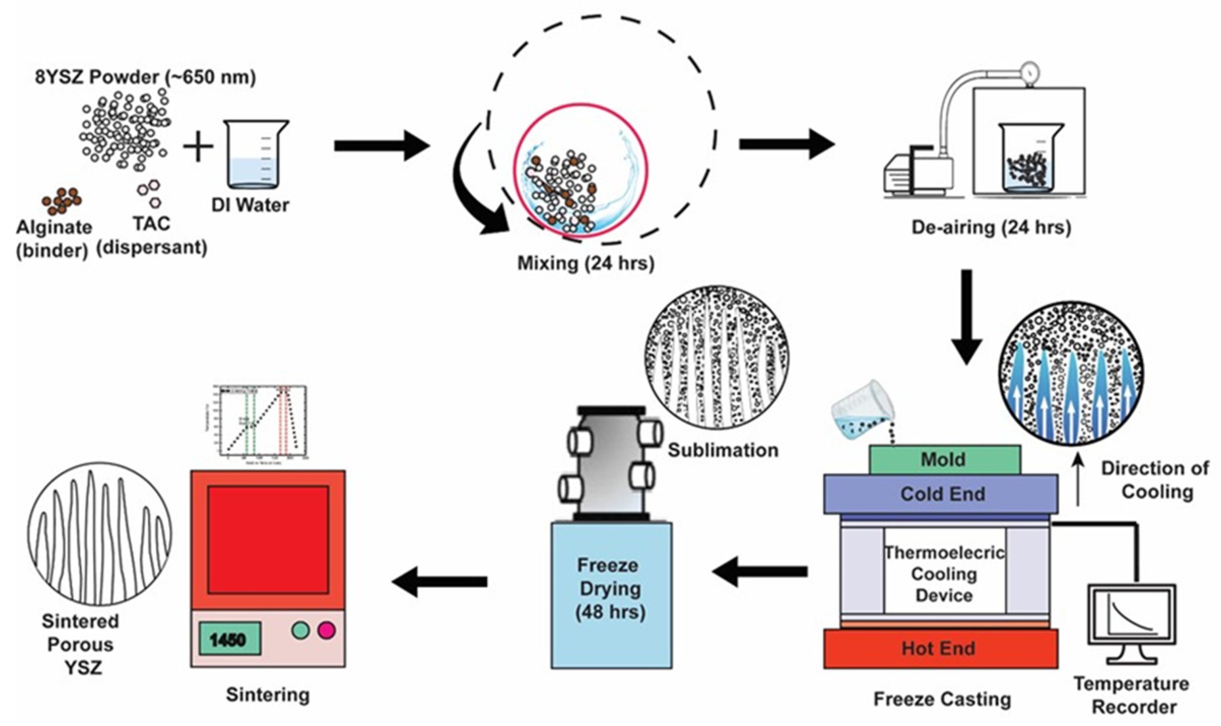
2.2. Preparation of YSZ Sheets

Freezing using a thermoelectric cold plate was employed to freeze-cast the slurry. At first, the cold plate and a 3D printed mold were cleaned with 70% isopropyl alcohol (IPA). Molds were then placed on the surface of the cold plate and the slurry was poured into the molds. A very thin fluorinated ethylene propylene (FEP) film was used in between the mold and the cold plate to ease the removal process of the frozen YSZ sheet after freeze-casting. After pouring the ceramic slurry into the mold, the thermoelectric plate was turned on, and the freeze-casting of the ceramic slurry was carried out from room temperature (23 °C) to −16 °C. The freeze-cast samples were then freeze-dried in a Labconco FreeZone2.5 freeze-dryer for 48 h at −50 °C and 300 Pa to sublimate the ice. Following freeze-drying, the green bodies were sintered at 1450 °C for 4 h in a ST-1700 C-445 (Sentro Tech(Strongsville, OH, USA)) high temperature box furnace in air environment.

2.3. Bulk Density

The bulk density of the YSZ sheets was measured using the Archimedes method. Three samples were prepared for density measurement. The density was measured to be 2.82 ± 0.04 g/cm3 and the porosity was calculated to be 45.50 ± 0.48%.

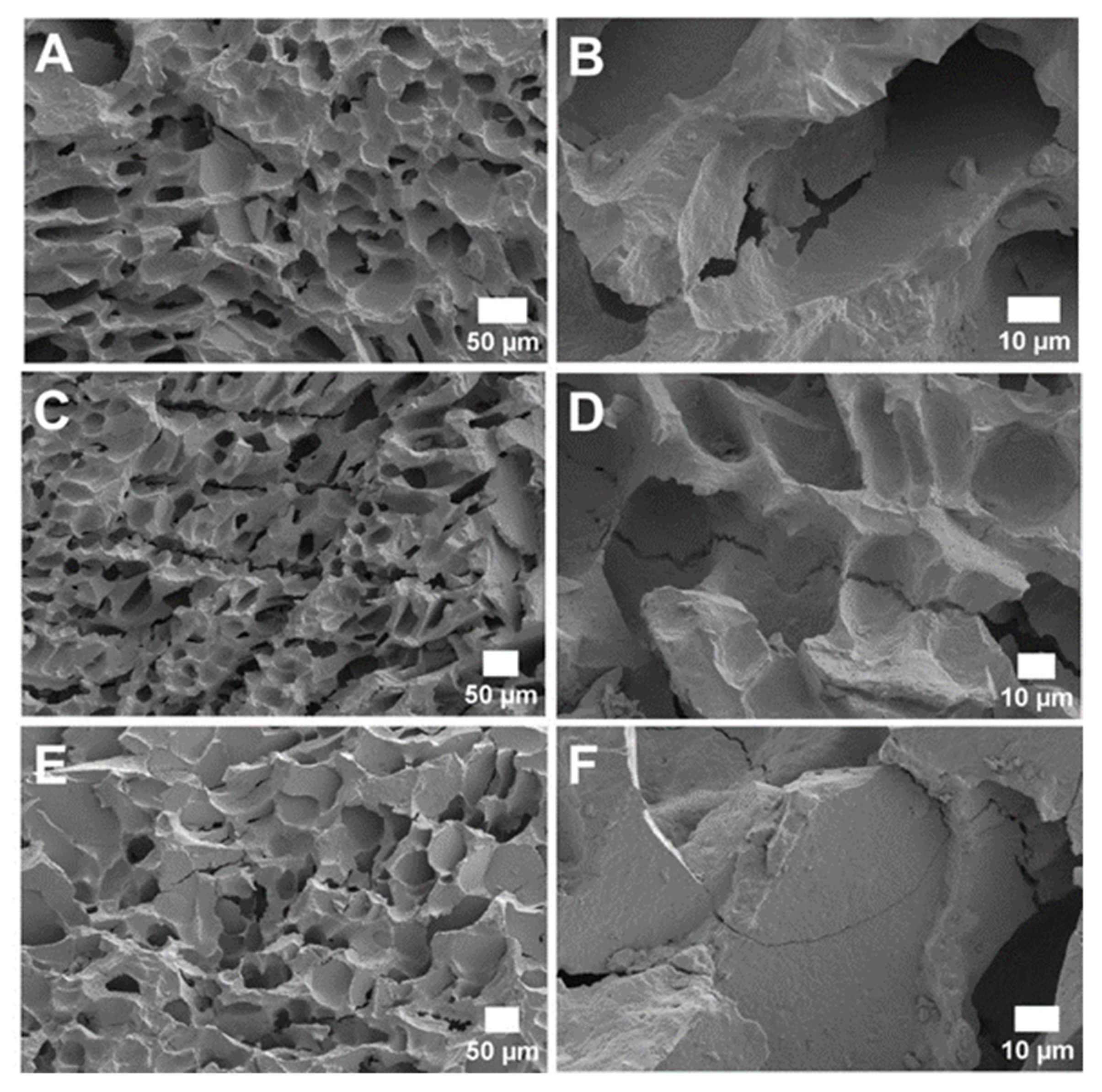
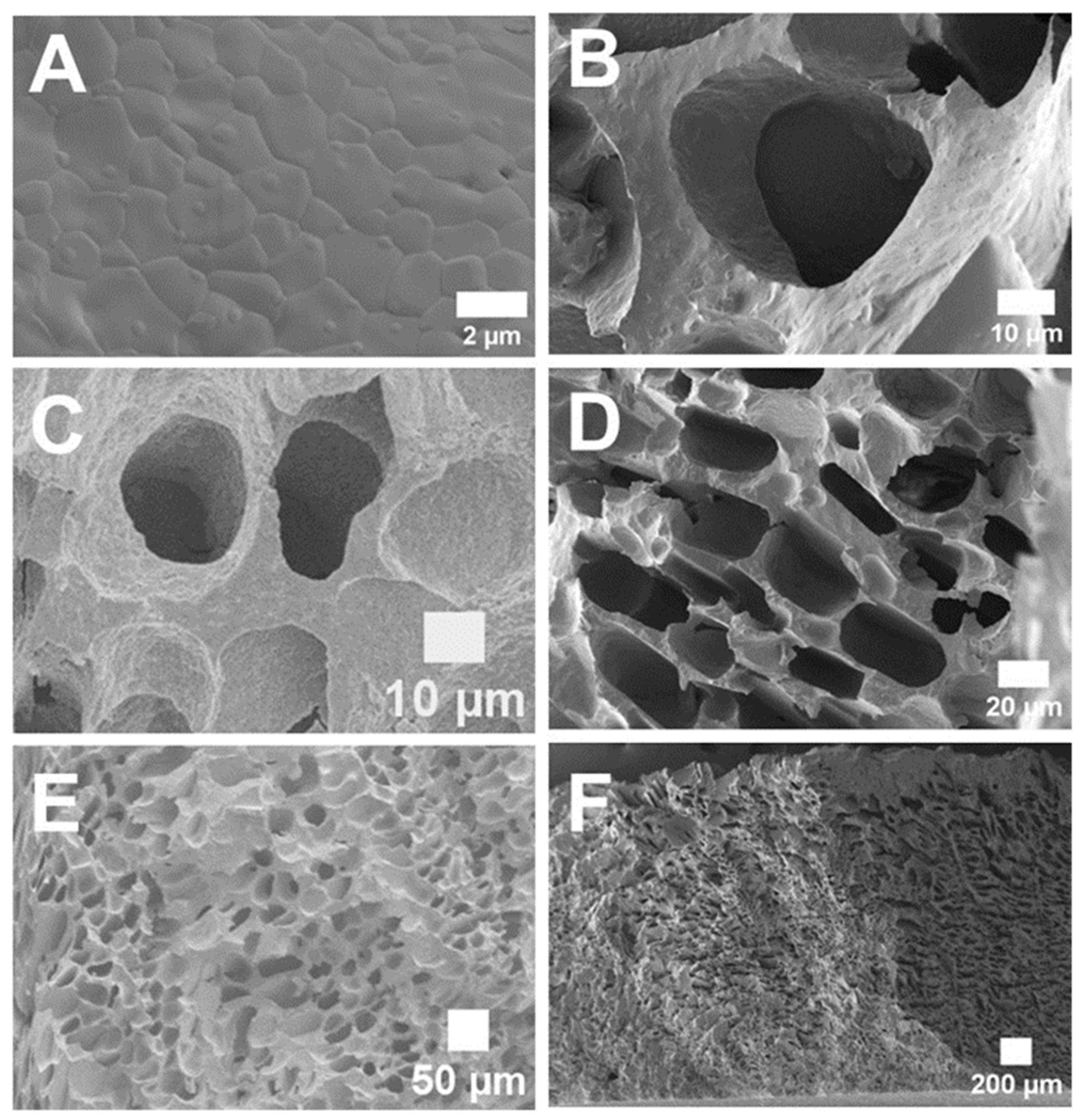
2.4. Electron Microscopy

A Zeiss Auriga SEM was used to observe pore morphology of the sintered porous YSZ samples.

2.5. Grain and Pore Size Measurement

The grain size of sintered YSZ was estimated by the standard intercept count method of ASTM E112-13 standard [19,20]. Here, 10 vertical and 10 horizontal lines were drawn randomly on one scanning electron microscopy (SEM) image using ImageJ software to measure the intercept lengths. The drawing of 20 lines yielded a total of 162 boundary intersections, which was sufficient for a reliable analysis. Subsequently, the mean linear intercept length, l ¯ , was calculated from l ¯ = P L , where P L refers to the number of grain boundary intersection points along the drawn lines per unit length [21].

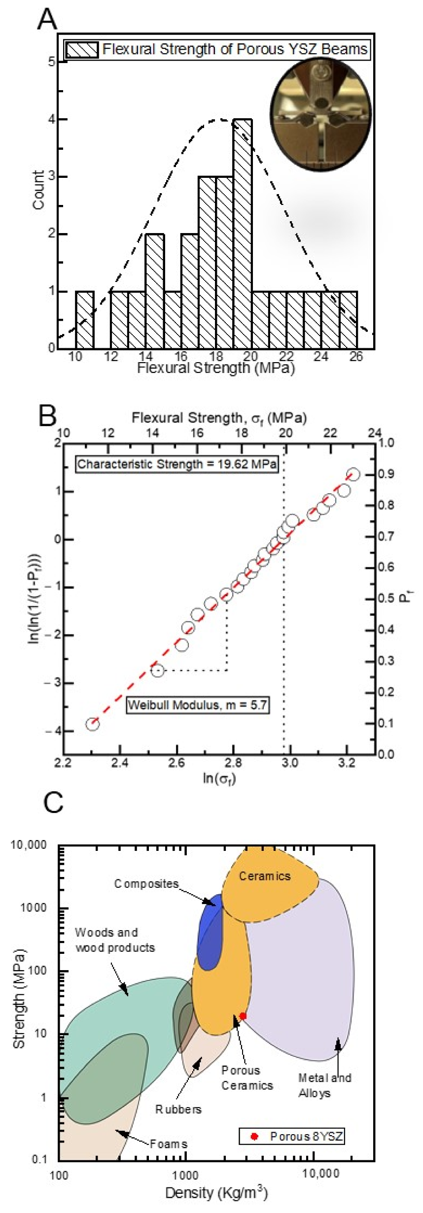
2.6. Characterization of Flexural Properties

The flexural strength of porous YSZ was measured using a SHIMADZU (AGS-X) universal testing machine. A total of 24 beams was prepared from fine polished YSZ sheets according to the ASTM standard (C1161-18) [22] for the three-point bending test. The dimensions of each beam were ~30 mm in length, ~2.2 mm in width and ~1.8 mm in height. The image of the polished YSZ sheet and beams are provided in Figure S3, in the supplementary materials. The three-point bending test was performed on the beams using a displacement rate of 0.05 mm/min and the span length was fixed to be 10 mm.

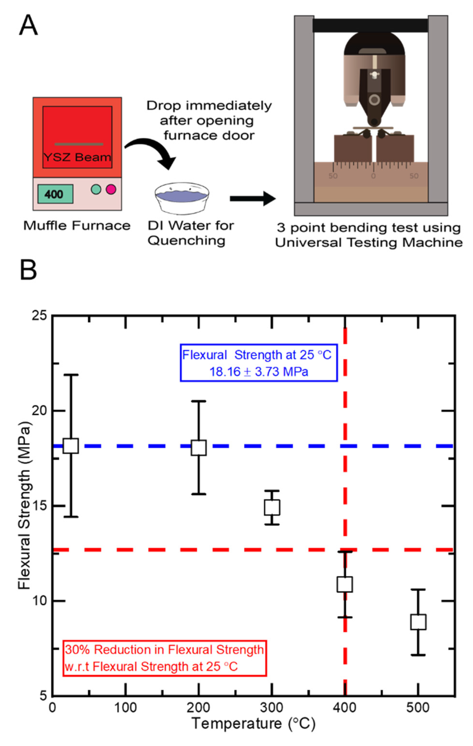
2.7. Characterization of Thermal Shock Behavior

The thermal shock resistance of porous YSZ beams was evaluated at temperatures of 200 °C, 300 °C, 400 °C and 500 °C. A batch of 30 beams was prepared from the polished YSZ sheets according to the ASTM standard [22] and six beams were randomly selected for each test condition. For each test condition, six beams were placed in a rectangular alumina crucible and put inside a box furnace. Then, the beams were slowly heated to the desired exposure temperature within 30 min and equilibrated at that temperature for 15 min. After equilibration, the door of the box furnace was opened and the alumina crucible containing the beams was immediately taken out with a high-temperature tong and promptly dropped in a room temperature DI water bath to induce thermal shock. Water volume was sufficient to prevent a temperature rise of more than 5 °C after test specimen quenching. The beams were then dried in a vacuum oven at 110 °C for 2 h. The flexural properties of five beams were measured by three-point bending test, following a similar protocol as mentioned in Section 2.6. For each test condition, one beam that went through thermal shock was kept intact for SEM imaging. The untested beams were further analyzed using SEM.

3. Results and Discussion

Figure 1 shows a schematic of the manufacturing process of porous YSZ. Briefly, the YSZ sheets were fabricated using freeze-casting on a thermoelectric cold plate from an aqueous slurry. The process involves slurry preparation by ball milling, freeze-casting, freeze-drying, and sintering. Details of the process are provided in the Section 2. The freeze-casting temperature profile and the image of the cast ceramic slurry into the mold is provided in Figures S1 and S2 in the supplementary material. During the freeze-casting process, the temperature profile was recorded until the process was completed.
Sintering of the green body includes two steps: (i) binder burnout to remove the alginate at 600 °C, and (ii) sintering at 1450 °C for transforming the binder-free green body into sintered ceramics. The heating profile for the two-stage sintering is as follows: increasing up to 600 °C at a heating rate of 1 °C/min and holding at 600 °C for 4 h; ramping up from 600 °C to 1450 °C at 1 °C/min heating rate, and after 4 h of sintering the temperature was reduced to room temperature at 5 °C/min cooling rate.
To attain acceptable mechanical properties, it is recommended to sinter the highly porous freeze-cast YSZ at 1450 °C or higher temperature [18]. Therefore, we selected the minimum recommended temperature of 1450 °C as the sintering temperature and selected 4 h of sintering period to ensure the conversion of porous green body into sintered body. Figure 2A represents the microstructure of the sintered surface of the porous YSZ. The average grain size was estimated to be ~1.30 ± 0.13 µm using the line intercepting method according to the ASTM standard E112-13. Most of the grains are hexagonal. A similar grain morphology has been reported in literature for 8YSZ sintered at 1400 °C [23].
Figure 2B,C represent the magnified image of open pores at transversely and longitudinally fractured planes, respectively. Based on SEM image micrographs, we observe a combination of spherical and tubular pore morphology, Figure 2D. The pore size varies from ~20 µm to 40 µm. In this work, we have used a cold thermoelectric plate at a temperature of −16 °C and thin sheets (0.18 mm) compared to traditional freeze-casting, in which several-centimeter molds are used for freeze-casting at a much lower temperature using liquid nitrogen [4,24]. It is known that the pore morphology in freeze-casting depends on the freezing temperature and temperature gradient, slurry viscosity, binder and solvent chemistry, particle size and volume fraction, among others. Depending on various parameters, different morphologies including lamellar, spherical, dendritic, among others can be obtained [6,18,25]. One of the advantages of using a thermoelectric cold plate for freeze-casting is that the process is potentially scalable (using larger thermoelectric plates). Essentially, the process provides a means to manufacture porous ceramics with open pores without using pore-formers. Oftentimes, large volume fraction of pore-formers is required to create open pore networks [26].
The anticipated applications of porous YSZ are for electrodes in SOFCs and SOECs, among others. In both devices mechanical properties of the electrodes play a significant role in reliable operations since the electrodes often function as the support structure and must withstand high thermal stresses during the operational cycles and endure various internal and external mechanical loads. The porosity is required to enable gas transport within the electrodes; however, the porosity can also significantly affect the mechanical properties of ceramics [7]. To quantify mechanical properties of the porous YSZ, we conducted flexural tests at room temperature as well as after a thermal shock test.
The flexural testing results of YSZ beams are summarized in Figure 3A. The porous beams exhibit a wide distribution of flexural strength from 10 MPa to 26 MPa, with an average flexural strength of 18.15 ± 3.7 MPa. For brittle ceramics, the presence of flaws affects mechanical strength. However, the flaws might not be consistent and not evenly distributed within the samples, and in some samples, flaws may be clustered inconsistently, which might initiate crack growth during mechanical testing. This should be considered while reporting mechanical strength data, and, accordingly, the ASTM standard C1161-13 requires reporting statistical data based on the Weibull distribution parameters.
We report the flexural strength of porous YSZ beams based on two parameter Weibull distribution analysis. The probability of beam failure can be written as P f = 1 e x p ( σ σ 0 ) m , where m is the Weibull modulus, and σ 0 is the characteristic strength. The Weibull modulus is a shape parameter that translates a specimen’s failure probability over a range of strength levels. The flexural strength of the specimens was ranked in an ascending order and assigned a corresponding probability of failure using P f = ( i 0.5 ) / N , where P f is the rank of the i t h specimen and N is the total number of tested specimens. Probabilities of flexural strengths are reported in terms of ln ( ln ( 1 ( 1 P f ) ) ) and ln ( σ ) . The characteristics strength of the porous YSZ beams were found to be ~19.62 MPa. The Weibull modulus, m, is then estimated to be 5.7 by fitting a straight line as the slope of the Weibull plot of ln ( ln ( 1 ( 1 P f ) ) ) against ln ( σ ) with an adjusted R2 value of 0.99.
For engineered ceramics, the Weibull modulus is reported to be in a range from 5 to 10. For 3D printed polymer-derived ceramics m = 3.7 was recently reported [27]. It is suggested that the random spatial distribution of pores dictates the range of the Weibull modulus of brittle porous materials [28]. Fan et al. [29] reported that for porous brittle ceramics the value of Weibull modulus lies in the range from 4 to 11.
Generally, m can have any value between 0 and , however, the higher the value of m, the less is the material’s variability in strength. In this work, we have found that the porous YSZ beams exhibited a high variability in the flexural strength, which yielded a lower Weibull modulus. From Figure 2 we observe that the pore structure exhibits a uniform distribution. However, it is possible that multiple pores may clump together and form large voids, and thus yield high defect density, which will induce variability in the results of three-point bending test. In addition, during the three-point bending test, the formation and propagation of cracks might vary in different samples, which will induce variability in the flexural strength. Apart from that, the grinding and polishing of YSZ sheets might induce stresses that affected mechanical properties as well. Figure 3C represents the characteristic strength of the porous 8YSZ beams, which is superimposed on the Ashby plot. As expected, the mechanical strength of the porous 8YSZ falls in the porous ceramic region.
The electrodes in SOFC and SOEC are subjected to thermal stress due to the high temperature ramps during operational cycles. In general, these devices operate at high temperatures, in a range from 600 to 1000 °C. Additionally, the non-uniform distribution of temperature generated during the operational cycle also leads to significant thermal stress at the cell level [30]. To quantify the thermal shock behavior of the manufactured YSZ, we followed the ASTM standard (C1525-18) [31]. Thermal shock resistance was analyzed in terms of the reduction of flexural strength at different temperatures with respect to the room temperature condition. The schematic of the thermal shock testing is shown in Figure 4A. Briefly, each beam was subjected to a high temperature for a duration of time, and subsequently was quenched inside a room-temperature water container, followed by testing its flexural strength (Figure S4). To systematically investigate the effect of high temperature on the mechanical strength of the porous YSZ, the initial testing temperature was selected to be 400 °C. The beams were held at the desired temperature for 15 min to obtain thermal equilibrium.
Our results showed that the porous YSZ beams exhibited a lower flexural strength of 10.87 ± 1.73 MPa, which was ~30.6–49.7% lower than the average flexural strength of the beams tested at 25 °C. The reduction of flexural strength with respect to the average flexural strength at 25 °C was calculated using the upper bound and lower bound values of the flexural strength obtained for the individual test conditions. According to the ASTM standard (C1525-18) [31], the critical temperature difference for thermal shock resistance is determined at such temperature difference between the exposure temperature and the water quenching temperature that induces a 30% reduction in flexural strength compared to the average flexural strength of the specimens tested at room temperature conditions. Hence, thermal shock resistance of porous YSZ beams were measured at 200 °C, 300 °C and 500 °C to map the reduction of the flexural strength, which is summarized in Figure 4B.
The reduced flexural strength of porous YSZ beams, tested at higher temperature, with respect to the flexural strength are summarized in Table 1. The flexural strength reduction of the porous YSZ beams was less than 30% up to the temperature of 300 °C. The maximum temperature for the thermal shock resistance measurement was 500 °C, where the flexural strength was reduced by 63.5%. From these results, we can determine the critical temperature for the thermal shock resistivity of porous YSZ beams to be 400 °C. We did not observe any visible cracks with the naked eye on the surfaces of the beams after quenching for any of the temperatures tested.
To observe the effects of thermal shock on the porous YSZ, we acquired SEM images of the surface of the beams that were only thermally shocked. We did not observe noticeable cracks on the surface of the beams that were thermally shocked at 200 °C. However, we observed significant number of cracks on the surfaces of the beams that were thermally shocked at temperatures of 300 °C to 500 °C. Representative SEM images are shown in Figure 5.
From Figure 5, we observe that cracks have been developed and propagated along the pore distribution channels for all the samples. In addition, from the SEM image of the beam thermally shocked at 500 °C, we found that the pore structures were exploded and did not retain their original shape. More SEM images are provided in the supplementary Figure S5. Thus, the development of cracks has compromised thermal shock resistance of the porous YSZ beams.
In general, the strength of ceramics is associated with the microstructure, pore size, shape and distribution, and contact (neck area) between particles [32]. For example, the flexural strength of spark-plasma-sintered YSZ evolved from 342.8 MPa to 43.1 MPa for a porosity in the range of 8 to 40.1% [33]. Nakamura, Keisuke, et al. [34] reported that for an increment in grain size of fully dense (6.06 gm/cm3) sintered 3% YSZ specimens from 0.30 µm to 0.63 µm, the flexural strength decreased from 1167 ± 144 MPa to 1068 ± 176 MPa, which is an 8.48% reduction in the flexural strength. This indicates that the sintered YSZ with larger grains exhibits a tendency to be lower in flexural strength. Therefore, the high porosity and larger grain size in the fabricated YSZ beams yielded lower flexural strength.
Hu et al. investigated the effect of freezing temperature during freeze-casting of porous YSZ ceramic, for samples as thick as 30 mm, and found out that the pore channel size decreased significantly with decreasing freezing temperature (−30 °C to −196 °C). Similarly, the porosity also decreased as freezing temperature decreased. In addition, they found that samples had remarkably low thermal conductivities (between 0.06 and 0.36 W/m K), which makes them suitable for thermal insulation applications [35]. Birchall et al. [36] proposed that larger pores degrade the tensile and flexural strength of brittle materials, such as hydraulic cements. Janssen et al. [37] also reported that pores act as nucleation sites for microcracks for brittle materials.
Generally, in highly porous ceramics, a relatively large number of cracks may initiate and propagate for a given thermal shock resistivity. It is suggested that the effect of porosity can be investigated from the point of view of both nucleation of fracture and degree of damage. In the literature it has been reported that porosity lowered the thermal shock fracture resistance but increased the thermal shock damage resistance for porcelain-based ceramics. The pores in ceramics can also function as crack arresters [38]. Cracks might be deflected or become arrested by the pores as the pores can consume some of the thermal shock stress [39]. Shen et al. [40] reported that the critical temperature difference for porous Al2O3/ZrO2 ceramics exhibits the higher critical temperature difference (ΔTc) for higher porosity than that of lower porosity ceramics. For example, Al2O3/ZrO2 ceramics with 6% porosity exhibited a rapid drop of flexural strength for a critical ΔTc of less than 200 °C, whereas the critical ΔTc improved to 300 °C and 400 °C when the porosity was increased to 31% and 43%, respectively. In this work, we have found that the porous 8YSZ beams exhibits more than a 30% drop of flexural strength when it is exposed to 400 °C. The critical temperature for ~98% dense 8YSZ has been reported to be 127 °C [41], and 3% mole yttria-doped tetragonal zirconia polycrystals (3Y-TZP, ~99% dense) exhibited a critical temperature of 325 °C [42].
This comparison of thermal shock resistivity is summarized in Figure S6, in the supplementary section. Compared to low-porosity or dense ceramics, highly porous ceramics have a higher penetrability, thus allowing the low-temperature medium (DI water of a quenching bath) to penetrate the whole ceramic scaffolds more easily and rapidly during the encounter of thermal shock. As a result, the thermal stress induced by the temperature difference between the surface and the interior of the ceramics becomes lower, and ceramics become capable of resisting higher thermal shock resistance. For this reason, the critical temperature of porous 8YSZ is higher than dense 8YSZ ceramics. In terms of the morphology of the porosity that may result in higher thermal shock resistance it can be said that pores that are perpendicular to the crack growth direction may better deflect and arrest cracks than pores that are aligned with the crack growth direction. Additionally, smaller, and better-distributed pores may be able to impart more fracture toughness than large or clustered pores.

4. Conclusions

Overall, our results show that freezing a thin sheet of YSZ slurry on a cold thermoelectric plate results in a porous ceramic with an open pore network (pore sizes of 20–40 µm), which is ideal for SOFC and SOEC applications. For long term stable operation in these devices, the critical temperature for the thermal shock resistivity of porous YSZ needs to be improved from the current 400 °C to well above 800 °C. Future studies may focus on engineering the grain size, powder particle size, optimization of the sintering temperature profile, as well as pore morphology (size, distribution, and shape) to achieve higher-performance porous YSZ with better thermal shock resistance properties.

Supplementary Materials

The following supporting information can be downloaded at: https://www.mdpi.com/article/10.3390/ceramics5030036/s1, Figure S1. The temperature profile of the thermoelectric plate during freeze casting of YSZ slurry; Figure S2. Freeze casting of YSZ slurry into molds on the surface of the thermoelectric cold plate; Figure S3. (A) Images of representative sintered YSZ sheets after polishing. (B) YSZ beams prepared from polished YSZ sheets for flexural test; Figure S4. Thermal shock test. (A) Taking the beams from the furnace after thermal equilibrium at a desired temperature. (B) Quenching the heated beams in DI water. (C) Quenched beams in DI water; Figure S5. SEM micrograph of the surface of thermally shocked beams tested at temperatures (A) and (B) 200 °C (C) and (D) 300 °C (E) and (F) 400 °C and (G–J) 500 °C; Figure S6. Comparison of flexural strength of (A) porous 8YSZ (this study), (B) dense 8YSZ and (C) 3Y-TZP at different temperatures. B and C are reproduced from [41,42].

Author Contributions

M.M.-J. and M.F.R. designed the research. M.F.R. carried most of the experimental work. M.M. did the SEM imaging and assisted in thermal shock experiment. M.M.-J. and M.F.R. contributed to the writing and editing of the manuscript. All authors have read and agreed to the published version of the manuscript.

Funding

This research is supported by the US National Science Foundation (CMMI award number 2152732) and AESF foundation under the AESF Foundation Research Program.

Institutional Review Board Statement

Not applicable.

Informed Consent Statement

Not applicable.

Data Availability Statement

Data are available upon request from the corresponding author.

Acknowledgments

This research is supported by the US National Science Foundation (CMMI award number 2152732) and AESF foundation under the AESF Foundation Research Program.

Conflicts of Interest

The authors declare no conflict of interest.

References

  1. Chen, Y.; Wang, N.; Ola, O.; Xia, Y.; Zhu, Y. Porous ceramics: Light in weight but heavy in energy and environment technologies. Mater. Sci. Eng. R Rep. 2021, 143, 100589. [Google Scholar] [CrossRef]
  2. Hammel, E.; Ighodaro, O.-R.; Okoli, O. Processing and properties of advanced porous ceramics: An application based review. Ceram. Int. 2014, 40, 15351–15370. [Google Scholar] [CrossRef]
  3. Zhang, F.; Li, Z.; Xu, M.; Wang, S.; Li, N.; Yang, J. A review of 3D printed porous ceramics. J. Eur. Ceram. Soc. 2022, 42, 3351–3373. [Google Scholar] [CrossRef]
  4. Huang, J.; Daryadel, S.; Minary-Jolandan, M. Low-Cost Manufacturing of Metal–Ceramic Composites through Electrodeposition of Metal into Ceramic Scaffold. ACS Appl. Mater. Interfaces 2019, 11, 4364–4372. [Google Scholar] [CrossRef] [PubMed]
  5. Hossain Bhuiyan, M.E.; Minary-Jolandan, M. Computational analysis of copper electrodeposition into a porous preform. AIP Adv. 2022, 12, 055020. [Google Scholar] [CrossRef]
  6. Deville, S. Freeze-Casting of Porous Ceramics: A Review of Current Achievements and Issues. Adv. Eng. Mater. 2008, 10, 155–169. [Google Scholar] [CrossRef]
  7. Cramer, C.L.; Ionescu, E.; Graczyk-Zajac, M.; Nelson, A.T.; Katoh, Y.; Haslam, J.J.; Wondraczek, L.; Aguirre, T.G.; LeBlanc, S.; Wang, H.; et al. Additive manufacturing of ceramic materials for energy applications: Road map and opportunities. J. Eur. Ceram. Soc. 2022, 42, 3049–3088. [Google Scholar] [CrossRef]
  8. Man, Y.; Ding, G.; Xudong, L.; Xue, K.; Qu, D.; Xie, Z. A review on porous ceramics with hierarchical pore structure by 3D printing-based combined route. J. Asian Ceram. Soc. 2021, 9, 1377–1389. [Google Scholar] [CrossRef]
  9. Polishko, I.O.; Brodnikovskyi, Y.M.; Brodnikovskyi, D.M.; Vasyliv, B.D.; Podhurska, V.Y.; Shevchenko, S.M.; Chedryk, V.I.; Andrzejczuk, M.; Vasylyev, O.D. Effect of Porosity on Strength and Electrical Conductivity of NiO–3.5YSZ Composite and Its Ni–3.5YSZ Cermet. Powder Metall. Met. Ceram. 2017, 56, 293–304. [Google Scholar] [CrossRef]
  10. Schafbauer, W.; Menzler, N.H.; Buchkremer, H.P. Tape Casting of Anode Supports for Solid Oxide Fuel Cells at Forschungszentrum Jülich. Int. J. Appl. Ceram. Technol. 2012, 11, 125–135. [Google Scholar] [CrossRef]
  11. Letilly, M.; Joubert, O.; Caldes, M.-T.; Salle, A.L.G.L. Tape casting fabrication, co-sintering and optimisation of anode/electrolyte assemblies for SOFC based on BIT07-Ni/BIT07. Int. J. Hydrog. Energy 2012, 37, 4346–4355. [Google Scholar] [CrossRef]
  12. Modjtahedi, A.; Hedayat, N.; Chuang, S.S.C. Diffusion-limited electrochemical oxidation of H2/CO on Ni-anode catalyst in a CH4/CO2-solid oxide fuel cell. Catal. Today 2016, 278, 227–236. [Google Scholar] [CrossRef] [Green Version]
  13. Marina, O.A.; Mogensen, M. High-temperature conversion of methane on a composite gadolinia-doped ceria–gold electrode. Appl. Catal. A Gen. 1999, 189, 117–126. [Google Scholar] [CrossRef]
  14. Yoon, K.J.; Lee, S.-I.; An, H.; Kim, J.; Son, J.-W.; Lee, J.-H.; Je, H.-J.; Lee, H.-W.; Kim, B.-K. Gas transport in hydrogen electrode of solid oxide regenerative fuel cells for power generation and hydrogen production. Int. J. Hydrog. Energy 2014, 39, 3868–3878. [Google Scholar] [CrossRef]
  15. Kong, W.; Zhang, Q.; Gao, X.; Zhang, J.; Chen, D.; Su, S. A method for predicting the tortuosity of pore phase in solid oxide fuel cells electrode. Int. J. Electrochem. Sci. 2015, 10, 5800–5811. [Google Scholar]
  16. Gaudillere, C.; Serra, J.M. Freeze-casting: Fabrication of highly porous and hierarchical ceramic supports for energy applications. Boletín Soc. Española Cerámica Vidr. 2016, 55, 45–54. [Google Scholar] [CrossRef] [Green Version]
  17. Liu, R.; Xu, T.; Wang, C.-A. A review of fabrication strategies and applications of porous ceramics prepared by freeze-casting method. Ceram. Int. 2016, 42, 2907–2925. [Google Scholar] [CrossRef]
  18. Du, Y.; Hedayat, N.; Panthi, D.; Ilkhani, H.; Emley, B.J.; Woodson, T. Freeze-casting for the fabrication of solid oxide fuel cells: A review. Materialia 2018, 1, 198–210. [Google Scholar] [CrossRef]
  19. ASTM. ASTM Standard Test Methods for Determining Average Grain Size; ASTM: West Conshohocken, PA, USA, 2021; p. E0112-13R21. [Google Scholar]
  20. Srinivasan, S.; Russ, J.C.; Scattergood, R.O. Grain size measurements using the point-sampled intercept technique. Scr. Metall. Mater. 1991, 25, 931–934. [Google Scholar] [CrossRef]
  21. Baddeley, A.; Jensen, E.B.V. Stereology for Statisticians, 1st ed; Chapman and Hall/CRC: Boca Raton, FL, USA, 2004. [Google Scholar] [CrossRef]
  22. ASTM. ASTM C1161-18, Standard Test Method for Flexural Strength of Advanced Ceramics at Ambient Temperature; ASTM: West Conshohocken, PA, USA, 2019. [Google Scholar]
  23. Zhang, J.; Huang, X.; Zhang, H.; Xue, Q.; Xu, H.; Wang, L.; Feng, Z. The effect of powder grain size on the microstructure and electrical properties of 8 mol% Y2O3-stabilized ZrO2. RSC Adv. 2017, 7, 39153–39159. [Google Scholar] [CrossRef] [Green Version]
  24. Huang, J.; Rubink, W.S.; Lide, H.; Scharf, T.W.; Banerjee, R.; Minary-Jolandan, M. Alumina–Nickel Composite Processed via Co-Assembly Using Freeze-Casting and Spark Plasma Sintering. Adv. Eng. Mater. 2019, 21, 1801103. [Google Scholar] [CrossRef]
  25. Scotti, K.L.; Dunand, D.C. Freeze casting—A review of processing, microstructure and properties via the open data repository, FreezeCasting.net. Prog. Mater. Sci. 2018, 94, 243–305. [Google Scholar] [CrossRef] [Green Version]
  26. Haugen, A.B.; Gurauskis, J.; Kaiser, A.; Søgaard, M. Graphite and PMMA as pore formers for thermoplastic extrusion of porous 3Y-TZP oxygen transport membrane supports. J. Eur. Ceram. Soc. 2017, 37, 1039–1047. [Google Scholar] [CrossRef] [Green Version]
  27. Mahmoudi, M.; Wang, C.; Moreno, S.; Burlison, S.R.; Alatalo, D.; Hassanipour, F.; Smith, S.E.; Naraghi, M.; Minary-Jolandan, M. Three-Dimensional Printing of Ceramics through “Carving” a Gel and “Filling in” the Precursor Polymer. ACS Appl. Mater. Interfaces 2020, 12, 31984–31991. [Google Scholar] [CrossRef] [PubMed]
  28. Keleş, Ö.; García, R.E.; Bowman, K.J. Stochastic failure of isotropic, brittle materials with uniform porosity. Acta Mater. 2013, 61, 2853–2862. [Google Scholar] [CrossRef]
  29. Fan, X.; Case, E.; Ren, F.; Shu, Y.; Baumann, M. Part I: Porosity dependence of the Weibull modulus for hydroxyapatite and other brittle materials. J. Mech. Behav. Biomed. Mater. 2012, 8, 21–36. [Google Scholar] [CrossRef]
  30. Wang, Y.; Shi, Y.; Yu, X.; Cai, N. Thermal shock resistance and failure probability analysis on solid oxide electrolyte direct flame fuel cells. J. Power Sources 2014, 255, 377–386. [Google Scholar] [CrossRef]
  31. ASTM. ASTM C1525-18 Standard Test Method for Determination of Thermal Shock Resistance for Advanced Ceramics by Water Quenching; ASTM: West Conshohocken, PA, USA, 2018. [Google Scholar]
  32. Hirata, Y.; Shimonosono, T.; Sameshima, T.; Sameshima, S. Compressive mechanical properties of porous alumina powder compacts. Ceram. Int. 2013, 40, 2315–2322. [Google Scholar] [CrossRef]
  33. Fregeac, A.; Ansart, F.; Selezneff, S.; Estournès, C. Relationship between mechanical properties and microstructure of yttria stabilized zirconia ceramics densified by spark plasma sintering. Ceram. Int. 2019, 45, 23740–23749. [Google Scholar] [CrossRef] [Green Version]
  34. Nakamura, K.; Adolfsson, E.; Milleding, P.; Kanno, T.; Örtengren, U. Influence of grain size and veneer firing process on the flexural strength of zirconia ceramics. Eur. J. Oral Sci. 2012, 120, 249–254. [Google Scholar] [CrossRef]
  35. Hu, L.; Wang, C.-A.; Huang, Y.; Sun, C.; Lu, S.; Hu, Z. Control of pore channel size during freeze casting of porous YSZ ceramics with unidirectionally aligned channels using different freezing temperatures. J. Eur. Ceram. Soc. 2010, 30, 3389–3396. [Google Scholar] [CrossRef]
  36. Birchall, J.D.; Howard, A.J.; Kendall, K. Flexural strength and porosity of cements. Nature 1981, 289, 388–390. [Google Scholar] [CrossRef]
  37. Janssen, D.; Aquarius, R.; Stolk, J.; Verdonschot, N. The contradictory effects of pores on fatigue cracking of bone cement. J. Biomed. Mater. Res. Part B Appl. Biomater. 2005, 74B, 747–753. [Google Scholar] [CrossRef] [PubMed]
  38. Hasselman, D.P.H. Elastic Energy at Fracture and Surface Energy as Design Criteria for Thermal Shock. J. Am. Ceram. Soc. 1963, 46, 535–540. [Google Scholar] [CrossRef]
  39. She, J.; Ohji, T.; Deng, Z.-Y. Thermal Shock Behavior of Porous Silicon Carbide Ceramics. J. Am. Ceram. Soc. 2002, 85, 2125–2127. [Google Scholar] [CrossRef]
  40. Shen, L.; Liu, M.; Liu, X.; Li, B. Thermal shock resistance of the porous Al2O3/ZrO2 ceramics prepared by gelcasting. Mater. Res. Bull. 2007, 42, 2048–2056. [Google Scholar] [CrossRef]
  41. Angle, J.P.; Steppan, J.J.; Thompson, P.M.; Mecartney, M.L. Parameters influencing thermal shock resistance and ionic conductivity of 8 mol% yttria-stabilized zirconia (8YSZ) with dispersed second phases of alumina or mullite. J. Eur. Ceram. Soc. 2014, 34, 4327–4336. [Google Scholar] [CrossRef]
  42. Sato, T.; Ishitsuka, M.; Shimada, M. Thermal shock resistance of ZrO2 based ceramics. Mater. Des. 1988, 9, 204–212. [Google Scholar] [CrossRef]
Figure 1. Schematic of the manufacturing of porous YSZ using the freeze-casting process.
Ceramics 05 00036 g001
Figure 2. (A) The microstructure of the porous YSZ sintered at 1450 °C for 4 h. (B) A magnified image of pores at transversely fractured plane. (C) A magnified image of pores at longitudinally fractured plane. (D) An image of spherical pores and tubular pores. (E,F) Lower magnification images of the pore morphology at a fractured surface.
Ceramics 05 00036 g002
Figure 3. (A) Distribution of the flexural strength of porous YSZ beams. (B) The Weibull analysis and characteristic strength of porous YSZ beams (n = 24). (C) An Ashby plot of flexural strength vs. density, in which the red dot denotes the porous YSZ in this work.
Ceramics 05 00036 g003
Figure 4. (A) The schematic shows the thermal shock experiment and the subsequent mechanical testing of porous YSZ. (B) Flexural strength of YSZ beams after thermal shock at the temperature range of 200 °C to 500 °C. The horizontal lines show the mean value of strength for room temperature (top line) and the 30% reduction point with respect to the top line (bottom line).
Ceramics 05 00036 g004
Figure 5. SEM micrographs of the surface of thermally shocked YSZ beams tested at temperatures (A,B) 300 °C, (C,D) 400 °C, and (E,F) 500 °C.
Ceramics 05 00036 g005
Table 1. Results of the thermal shock experiment for porous YSZ beams.
Temperature (°C)Flexural Strength (MPa)Characteristic Strength (MPa)Strength Reduction in (%) w.r.t. Flexural Strength at 25 °C
2518.16 ± 3.7319.62-
20018.06 ± 2.44-
30014.92 ± 0.8812.9–22.7
40010.87 ± 1.7330.6–49.7
5008.89 ± 1.7241.6–60.5
Publisher’s Note: MDPI stays neutral with regard to jurisdictional claims in published maps and institutional affiliations.

