Article

Design of a High-Speed Pavement Image Acquisition System Based on Binocular Vision

1
School of Mechanical and Precision Instrument Engineering, Xi’an University of Technology, Xi’an 710048, China
2
School of Materials Science and Engineering, Xi’an Jiaotong University, Xi’an 710049, China
*
Author to whom correspondence should be addressed.
Appl. Syst. Innov. 2025, 8(6), 173; https://doi.org/10.3390/asi8060173
Submission received: 7 September 2025 / Revised: 10 October 2025 / Accepted: 30 October 2025 / Published: 18 November 2025

Abstract

The acquisition of images of road surfaces not only establishes a theoretical foundation for road maintenance by relevant departments but also is instrumental in ensuring the safe operation of highway transportation systems. To address the limitations of traditional road surface image acquisition systems, such as low collection speed, poor image clarity, insufficient information richness, and prohibitive costs, this study has developed a high-speed binocular-vision-based system. Through theoretical analysis, we developed a complete system that integrates hybrid anti-shake technology. Specifically, a hardware device was designed for stable installation at the rear of high-speed vehicles, and a software algorithm was implemented to develop an electronic anti-shake module that compensates for horizontal, vertical, and rotational motion vectors with sub-pixel-level accuracy. Furthermore, a road surface image fusion algorithm that combines the stationary wavelet transform (SWT) and nonsubsampled contourlet transform (NSCT) was proposed to preserve multi-scale edge and textural details by leveraging their complementary multidirectional characteristics. Experimental results demonstrate that the fusion algorithm based on SWT and NSCT outperforms those using either SWT or NSCT alone across quality evaluation metrics such as QAB/F, SF, MI, and RMSE: at 80 km/h, the SF value reaches 4.5, representing an improvement of 0.088 over the SWT algorithm and 4.412 over the NSCT algorithm, indicating that the fused images are clearer. The increases in QAB/F and MI values confirm that the fused road surface images retain rich edge and detailed information, achieving excellent fusion results. Consequently, the system can economically and efficiently capture stable, clear, and information-rich road surface images in real-time under high-speed conditions with low energy consumption and outstanding fidelity.

1. Introduction

Certainly, highways are one of the important infrastructures of national development and are one of the factors important for the development of society. Long-term running of vehicles and the influence of natural causes lead the surface of highways to erode and cause cracks, potholes, craters, bulges, and so on. These defects not only undermine driving safety but also hinder people’s travel. Poor maintenance brings about a high risk of severe accidents and serious economic losses. As a result, regular maintenance is required for keeping the roads sound and safe. Road maintenance calls for scheduled data collection on the surface conditions of the road to detect defects and help enforcement authorities to address them specifically. However, existing popular crowdsourced app-driven data collecting models suffer from deficiencies such as great dependence on network connections, limited geographic coverage, and low user involvement. These limitations lead to the poor quality of the data and affect the emergency management efficiency of the administrative agents. To overcome these challenges, it is essential to deploy intelligent road monitoring systems with high-resolution imaging and powerful real-time analysis tools for highly accurate defect detection. Such systems can dynamically inform maintenance strategies, offering substantial practical value for optimizing road network governance [1].
The advancement of smart transportation systems [2] has emerged as a pivotal benchmark for urban modernization efficiency, safety, and sustainability through technological innovation. Within this framework, autonomous driving technology is emerging as a transformative catalyst for next-generation mobility solutions. Nevertheless, despite its revolutionary potential, this technology confronts critical implementation barriers, including operational reliability concerns in real-world scenarios, particularly in complex environments such as urban thoroughfares, highway networks, and rural roads, where perception and decision-making algorithms demonstrate constrained capabilities. To overcome these technical hurdles, sophisticated road surface image acquisition systems have become indispensable infrastructure components. These systems not only provide cost-effective and high-fidelity data streams for vehicular perception modules but also enable situational awareness through surface condition analytics, thereby comprehensively improving system robustness and safety parameters.
Consequently, the deployment of such acquisition systems holds substantial engineering significance for smart transportation evolution as vital technical enablers for achieving intelligent, efficient, and secure transportation systems. Current road surface inspection systems primarily rely on dedicated vehicles to capture high-quality image data for damage detection. In 2002, the Research Group of Intelligent Inspection Vehicle of Highway at Nanjing University of Science and Technology pioneered China’s first intelligent road inspection vehicle [3]. Equipped with a high-speed digital sensor, it achieved image capture at 70 km/h with a resolution of 1300 × 1030 and 10 fps. However, while effective on smooth roads, the system could not compensate for motion blur caused by vibrations. In 2012, Wuhan Opto Valley Excellence Technology Co., Ltd. (Wuhan, China) introduced the ZOYON-RTM system [4], automating rapid image acquisition during standard driving at speeds of up to 100 km/h. Despite these advances, motion blur remained unresolved. For mountainous terrains, the National Road Maintenance Management Research Center developed the Customer Information Control System (CiCS) road information acquisition system, operating at 30 km/h [5], with specialized stabilization. Yet, its low speed severely limited efficiency.
Technological integration saw progress in 2019 when Tsinghua University researchers Zhou Youjia and Guo Runhua developed a 3D inspection system combining road surface data with environmental mapping via LiDAR and stereo cameras. Recently, unmanned aerial vehicles have appeared as alternatives, with dual optical–electronic stabilizations cancelling the vibration artifacts. However, they are too expensive and massive and have too heavy sensor loads. In summary, there are three aspects of bottlenecks: limit in speed (120 km/h), poor deblurring algorithm, and costly multi-sensor integration. Overcoming these requires breakthroughs in real-time image optimization and adaptive sensor fusion.
The escalating demands of modern infrastructure management—requiring simultaneous achievement of high-throughput operation (>100 km/h), cost-efficiency (<CNY 50,000 per unit), and submillimeter-level precision—have rendered conventional road inspection systems obsolete. This paper presents a binocular vision-based imaging system specifically engineered for high-velocity pavement quality assessment, addressing the critical need for vibration mitigation in mobile sensing platforms. To meet the dual challenge of high-speed operation (>100 km/h) and submillimeter precision in road surface imaging, we developed a bimodal stabilization system integrating passive mechanical dampers with adaptive computational correction. The demands of road maintenance tasks and stringent management requirements dictate that the system operate at speeds exceeding 100 km/h. At such high speeds, slight vehicle vibrations can cause motion blur in the captured road surface images. This blur, whether global or local, leads to a severe loss of detail. To address this issue, a hybrid anti-shake technology combining hardware-based mechanical stabilization and software-based electronic stabilization was proposed. Compared to standalone mechanical or electronic stabilization, the hybrid approach integrates physical compensation with algorithmic processing, enabling it to handle a wider range of vibrations, including high-frequency minor vibrations and low-frequency major vibrations. It performs exceptionally well in complex scenarios (e.g., motion capture, low-light environments). While standalone mechanical stabilization has minimal impact on image quality, it may still have blur under extreme vibrations. In contrast, hybrid anti-shake technology effectively reduces image quality loss by further compensating with electronic stabilization. Additionally, hybrid anti-shake dynamically adjusts stabilization strategies based on the type and intensity of vibrations, providing more flexible and efficient stabilization. Although hybrid anti-shake requires the integration of both mechanical components and algorithmic support, its overall cost may be lower than solutions relying solely on high-performance mechanical stabilization. By comparison, standalone electronic stabilization mainly relies on algorithmic processing, with limited compensation capability for large vibrations, whereas hybrid anti-shake significantly enhances stabilization effectiveness through the physical compensation of mechanical stabilization. Electronic stabilization often requires cropping the frame to compensate for vibrations, resulting in a loss of field of view, whereas hybrid anti-shake reduces the reliance on frame cropping through mechanical stabilization, preserving more field of view. Moreover, hybrid anti-shake reduces blur through mechanical stabilization and further optimizes the image using electronic stabilization, resulting in overall image quality superior to standalone electronic stabilization. Furthermore, electronic stabilization may introduce delays due to algorithmic processing, whereas hybrid anti-shake effectively reduces latency by compensating for vibrations in real time through mechanical stabilization. Overall, hybrid anti-shake technology demonstrates significant advantages in stabilization effectiveness, image quality preservation, and real-time performance, making it an ideal solution for complex scenarios. Given that existing systems rely on single stabilization technologies and struggle to balance cost and performance, this paper proposes hybrid anti-shake as a solution to this contradiction.
This hybrid anti-shake technology simultaneously achieves stabilization during the image acquisition and image processing phases, thereby enhancing the accuracy and reliability of high-speed acquisition while ensuring the longevity and long-term accuracy of the acquisition system. For pavement image information acquisition systems, in addition to employing mechanical fixation devices to stabilize image clarity, traditional approaches for enhancing image quality include image transformation, image enhancement, and image restoration. Youla et al. applied convex set projection theory to image restoration, achieving notable improvements in image clarity [6]. Glasner et al. proposed a single-image super-resolution method that leverages internal image statistics combined with prior knowledge and edge information to enhance image sharpness [7]. Dong et al. introduced a deep learning-based approach for image super-resolution, utilizing a deep convolutional neural network as a mapping model to reconstruct high-resolution images from low-resolution inputs [8]. Zhang et al. developed a deep convolutional neural network-based method for image denoising capable of handling multiple general image denoising tasks [9]. Chen et al. implemented an end-to-end trainable fully convolutional network for low-light image processing, directly processing raw sensor data to replace conventional image processing pipelines and thereby enhance image clarity [10]. Wang Yang et al. presented a fusion method combining generative adversarial networks with multi-scale recursive networks, effectively addressing motion-induced blur and achieving satisfactory image restoration [11].
In summary, while the aforementioned methods can directly improve image clarity, they heavily depend on training datasets and computational time, requiring image processing systems with substantial computational and storage resources. The design and development of pavement image acquisition systems by researchers worldwide predominantly rely on single imaging devices without dedicated modules for stabilizing image clarity. Consequently, these systems cannot eliminate motion blur caused by minor vibrations during high-speed acquisition in real-time, resulting in compromised image quality and information richness. In contrast, image fusion technology can not only average pixel values across multiple images to reduce random noise but also complement information from different images, thereby enhancing both clarity and informational richness.
Currently, most pavement information acquisition systems developed by global research teams utilize single cameras for data collection, producing individual pavement images. Even systems equipped with multiple cameras primarily expand the scope and quantity of image acquisition without improving overall image quality. Such systems no longer meet the requirements of road maintenance management. The coordinated utilization of multi-camera pavement image information to enhance both clarity and detail richness has become a critical challenge. Image fusion technology can address this issue through three hierarchical levels: pixel-level, feature-level, and decision-level fusion [12]. Pixel-level fusion directly combines information from multiple source images, preserving fine details and improving image quality, making it a research focus in recent years. Feature-level fusion involves extracting and comprehensively analyzing image features before integration [13]. Compared to pixel-level fusion, this approach incurs greater information loss. Decision-level fusion primarily employs feature extraction and classification for integration but requires extensive decision systems, resulting in the highest information loss. Based on this comparative analysis, research on image fusion technology for high-speed pavement information acquisition systems will focus on pixel-level fusion to enhance image clarity and information richness.
Subsequently, high-speed acquired road surface images were transmitted in real time to a PC via an HDMI interface for pixel-level image fusion processing. An image fusion algorithm based on a stationary wavelet transform and nonsubsampled contourlet transform was designed to further improve the clarity and information richness of road surface images. Finally, a high-speed road surface acquisition experiment was carried out on an unobstructed road section. By analyzing the clarity S of the acquired images and comparing it with traditional mechanical anti-shake technology, the feasibility and advantages of the hybrid anti-shake technology were demonstrated. Additionally, image fusion tests were performed using the acquired original images, with QAB/F, SF, MI, and RMSE as evaluation metrics. By comparing the results of the image fusion method based on SWT (stationary wavelet transform) and NSCT (nonsubsampled contourlet transform) with those obtained using SWT and NSCT individually, the feasibility of the SWT- and NSCT-based image fusion method was validated.

2. Related Works

This study focuses on high-speed road surface information acquisition technology driven by binocular vision, developing a low-latency embedded system. Based on demand analysis, the selection of core components was completed, including the OV2710 binocular CMOS image sensor, DDR3 SDRAM image caching module, HDMI image transmission interface, and Pro FPGA core control system. In this study, methods for enhancing image clarity during high-speed acquisition were also explored. The designed system was stably installed on an acquisition vehicle to validate its high-speed image acquisition performance. Additionally, a pixel-level image fusion algorithm was designed to process the acquired images, and the results were evaluated and analyzed using objective quality assessment methods.

2.1. Design of a High-Speed Road Surface Image Acquisition System

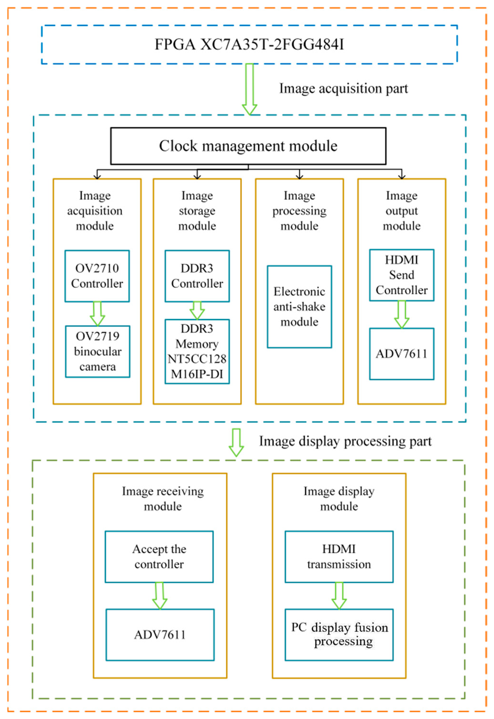
This system utilizes an FPGA hardware development platform to acquire, process, transmit, and store road surface images while the acquisition vehicle operates at high speeds and then transmits the images in real time to a PC for fusion processing. The entire system mainly consists of two parts: the road surface image acquisition module, which includes the FPGA hardware processing platform and binocular image sensors, and the image display and processing module. The acquisition module is responsible for high-speed image capture, whereas the display and processing module comprises a computer that handles real-time image transmission, reception, and fusion processing. The two modules are connected via an HDMI interface. Figure 1 shows the overall architectural design diagram of the system [14].
(1)
Image Acquisition Module: Initialize the binocular OV2710 image sensor and configure its register.
(2)
Image Storage Module: High-speed road surface images.
(3)
Image Processing Module: Deblur is performed on real-time road surface images.
(4)
Image Transmission Module: Package and transmit the processed image data.
(5)
Image Reception Module: Extract road surface image data.
(6)
Image Display Module: The acquired road surface images were displayed on a PC, and image fusion processing was performed.
The image acquisition module of this system consists of an image sensor, and the selection of the image sensor directly affects the functionality of the high-speed road surface image acquisition system. OV2710, chosen for this system, is a high-performance CMOS image sensor characterized by low power consumption, compact size, and high resolution. In addition, it supports the MIPI interface, offering significant advantages in high-speed data transmission.
The selected binocular OV2710 image sensor consisted of two OV2710 devices with different addresses and a binocular conversion board connected to the FPGA via the MIPI CSI-2 interface. As shown in Table 1, which compares the parameters of common cameras, the MIPI CSI-2 interface used in the system significantly outperforms DVP and USB 3.0 in terms of high-speed road surface image data transmission. It supports both high-speed and low-power modes, with a transmission speed range of 80–1000 Mbps, enabling more efficient and faster image data transmission and high-quality image information.
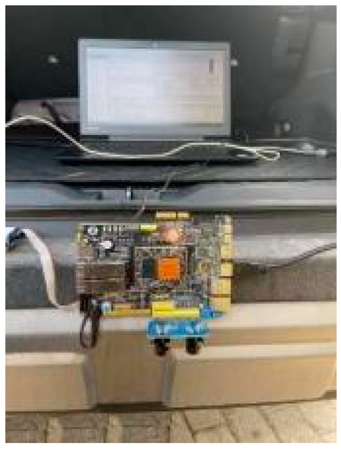
In this system, the image storage module is mainly responsible for the real-time caching of road surface images. DDR3 SDRAM [15], an advanced memory technology, features a more complex and refined internal structure and operational mode than its predecessors. It can perform two data transfers in a single clock cycle, thereby achieving a higher data-transfer rate than traditional SDRAM. Consequently, the system employs the NT5CC128M16IP-DI DDR3 SDRAM chip, which operates at a speed of up to 800 MHz and provides a maximum bandwidth of 25.6 Gbps, with a supply voltage of 1.35 V. This chip is capable of satisfying the high-capacity memory and high-bandwidth requirements of high-speed acquisition scenarios. The system’s physical diagram is shown in Figure 2.

2.2. Methods for Enhancing Clarity in High-Speed Road Surface Acquisition Systems

The system must perform high-speed image acquisition while operating at high speeds, requiring the acquired images to undergo clarity enhancement. The primary issue to be addressed in the clarity enhancement method for the acquisition system is anti-shake stabilization. Therefore, in this study, a hardware mounting device was employed to install the system on an acquisition vehicle. Hardware fixation is a method of stabilizing the equipment through physical means to reduce shaking and vibration. In the field of high-speed image acquisition, hardware fixation is commonly used to ensure that the imaging device remains stable during the capture process, thereby obtaining clear and stable images or videos. Common hardware fixation methods include the use of tripods, stabilizers, and gimbals. Although these traditional methods can effectively reduce the shaking and vibration of image acquisition devices, they cannot shield the system from external environmental interference or add additional mechanical components that increase the system weight and cost. Thus, they are not suitable for high-speed road surface image acquisition systems.
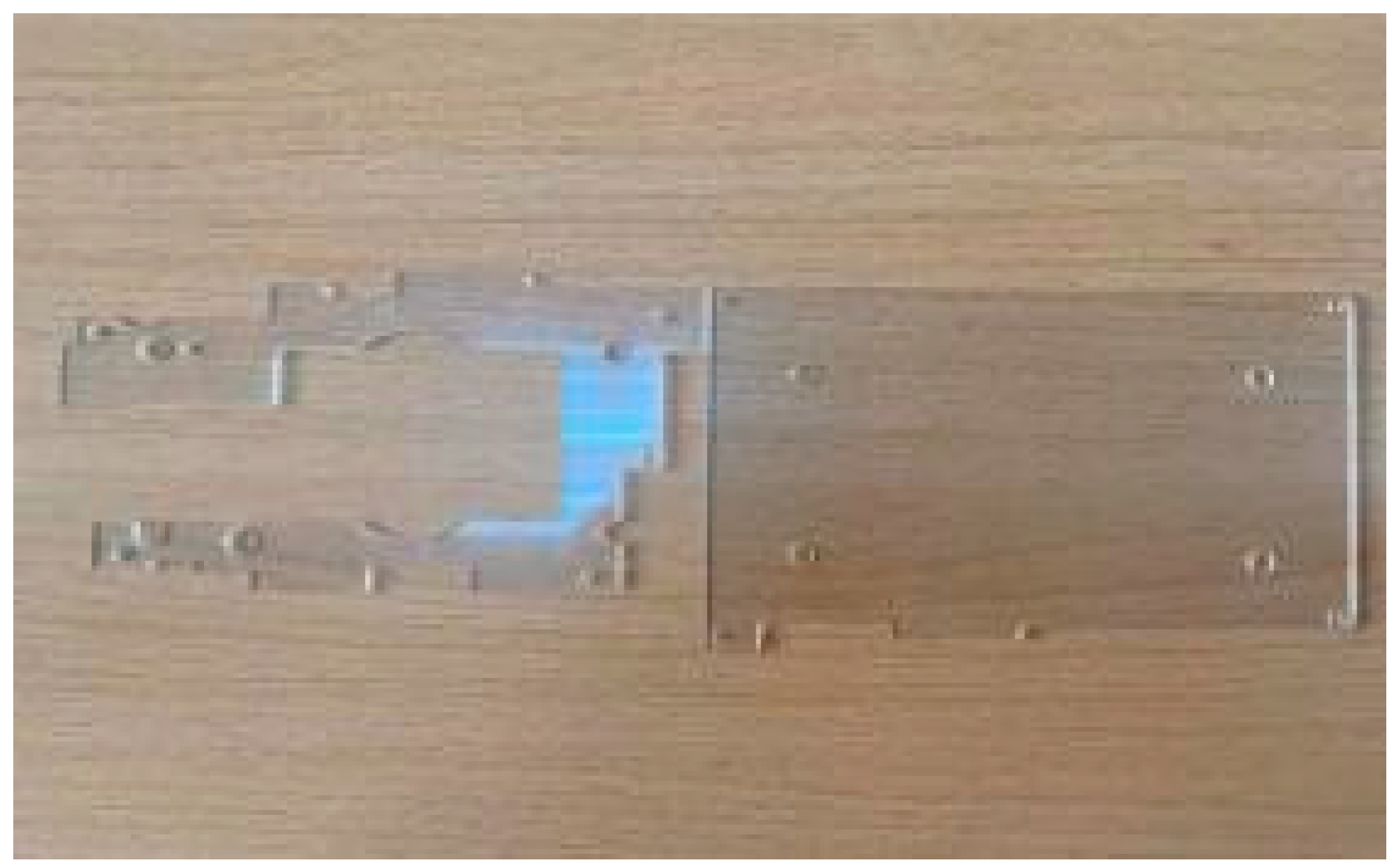
Considering the system’s appearance and dimensional characteristics, in this study, a protective casing was innovatively designed to shield the system from external interference. This casing not only effectively blocks external disturbances but also reduces shaking and vibration through adhesive fixation. Therefore, to avoid increasing the weight and cost of the system, a material that is highly durable, resistant to damage, lightweight, and cost-effective is required. Acrylic sheets are common transparent plastic materials that offer high transparency, wear resistance, and weather resistance. With special treatment, they can withstand erosion from ultraviolet rays and other natural environmental factors. In addition, acrylic sheets have excellent processing properties, allowing for both mechanical machining and thermal forming, as shown in Figure 3.
Therefore, the hardware stabilization shell of the system was constructed using an acrylic material. The acrylic shell has excellent weather resistance, effectively withstanding the effects of ultraviolet rays, rain, and temperature fluctuations, and is resistant to yellowing and aging during long-term outdoor use. Its surface hardness is high, providing scratch resistance and maintaining its gloss and transparency over extended periods. Acrylic acid can maintain stable performance across a wide temperature range from −40 °C to 90 °C, making it suitable for various climatic conditions. Additionally, it has high mechanical strength and can withstand certain pressures and loads without deformation or cracking, making it ideal for multiple extreme environments. The acrylic protective shell adopts a curved or arched design that distributes and disperses external forces along the arc or arch, ensuring that the force is evenly distributed across the entire structure. Furthermore, a thin-walled structure was employed to reduce the weight while maintaining sufficient strength. To enhance the mechanical properties of thin-walled structures, reinforcing ribs are designed inside the shell, increasing the structural rigidity and stability and improving the shell’s resistance to deformation and fracture. To securely connect the acrylic shell to the main system structure without damaging it, the dimensions of the shell were designed to closely match those of the system, forming a unified whole. Considering the safety and stability of the system, the acrylic shell was firmly adhered to the rear of the acquisition vehicle using adhesive bonding, which connects the two surfaces through intermolecular forces, providing good sealing and adequate strength. This stabilization method not only offers additional safety but also ensures the stability of the system during high-speed operation of the acquisition vehicle through tight bonding, thereby reducing motion blur in high-speed image acquisition caused by vibrations or bumps.The fixed position of the system is shown in Figure 4.
In the design of the hardware stabilization device of the system, the shielding of external environmental interference during high-speed image acquisition was considered. Encapsulating the system in an acrylic shell effectively prevents interference from dust, noise, moisture, and other factors in complex external environments that can affect image quality. This not only enhances the accuracy and reliability of high-speed image acquisition and improves the overall performance of the system but also provides a solid foundation for the system’s long-term stability and service life.
However, by relying solely on external mechanical hardware stabilization for the system, we can only ensure stability during the image acquisition phase and cannot guarantee the accuracy of the high-speed acquisition. Therefore, an internal stabilization technology that does not increase the system’s weight or cost and can achieve stabilization during the image processing phase is required. Thus, this system incorporates electronic image stabilization (EIS) along with mechanical hardware stabilization. This hybrid stabilization technology provides a more comprehensive and robust anti-shake effect, achieving stabilization in both image acquisition and processing phases.
Electronic image stabilization (EIS) technology utilizes digital image processing to detect and compensate for shifts in the image sequences. It can compensate for not only optical system movements but also various other types of motion. Compared with traditional optical and mechanical stabilization methods, EIS offers advantages such as simplicity of operation, precise results, compact size, and low cost. By detecting and analyzing the motion in image sequences, it isolates global motion vectors and compensates for them during image display, achieving image stabilization and producing clear and stable images.
EIS technology mainly consists of three modules: a motion estimation module, a motion decision module, and a motion compensation module. The key technologies involved are global motion estimation, motion-vector filtering, and image-compensation correction. The motion estimation module uses mathematical methods to estimate the motion of an image sensor in an image sequence describing global motion. The interframe difference method was employed as the estimation technique, which calculates the interframe motion vectors using block matching. As shown in Figure 5, the arrows represent the motion vectors from the ith frame to the (i + 1)th frame.
The motion decision module analyzes the motion vectors to distinguish between the scanning motion of the system and abnormal motions during high-speed acquisition. By employing motion vector filtering, abnormal jitter components were extracted while retaining stable scanning components. Subsequently, a fixed block shape was determined, with each shape being 57 pixels and the number of frames being 57 frames. Optimal block matching is achieved through an objective function expressed as
d j = i = 0 56 ( x M x ) 2 f i ( x , y ) + i = 0 56 ( y M y ) 2 f i ( x , y )
In the equation, i represents the number of pixels within the block, j denotes the number of matchable blocks, MxMy indicates the centroid coordinates of the block to be matched, and ƒi (x, y) represents the pixel values within the block. For the same reference block, min{dj} corresponds to the best-matched block. x and y are the coordinates of pixel points.
The motion compensation module conducts a detailed analysis of the system’s global motion vectors, effectively extracting the jitter components from the global motion vectors and compensating for them in real time. Electronic image stabilization detects the relative motion between two frames, thereby isolating translational and rotational movements of the image sensor. Based on the motion vectors, the position of the current frame was adjusted to cancel out the jitter.
Real-time compensation for high-speed road surface images is crucial during the operation of the electronic image stabilization module. Therefore, to ensure the coordination of this module with the image acquisition module, image caching module, and image output module, a 20 ms delay counter is designed in the system. When the system begins acquiring road surface images, the image acquisition module is first activated, which performs high-speed continuous acquisition of multiple frames. Simultaneously, the sensor input module receives data from the image sensor, and the image-caching module stores the acquired image data in real time. By introducing a fixed time delay, we can ensure that each module has sufficient time to complete the processing of image data and prevent data conflicts or losses owing to excessively fast processing speeds.
As shown in Figure 6a, the road surface image without anti-shake processing has overall blur. From Figure 7, it can be observed that the high-speed road surface image contains horizontal, vertical, and rotational jitter components, displaying large-amplitude and high-frequency fluctuations. Figure 6b demonstrates that the image clarity improves and no blur is observed after electronic image stabilization compensates for the jitter components in all directions. Therefore, it was proven that the use of electronic image stabilization technology can effectively compensate for the horizontal, vertical, and rotational motion vectors of the image in real time. This also confirms the feasibility of adopting the electronic image stabilization technology in the image clarity enhancement module of this system.
To evaluate the quality of the images acquired by the system using hybrid anti-shake technology, the image clarity metric S was introduced. Objective evaluation methods for image clarity include the full-reference, reduced-reference, and no-reference approaches. In the context of road surface image quality evaluation, because the images acquired by the system at high speeds are stage-specific and the original images cannot be obtained, a no-reference objective evaluation method is used to analyze the clarity of high-speed road surface images. Reblur theory was used to generate reference images, and a full-reference method was applied to assess the degree of information loss in the images. Greater information loss indicates higher image clarity [16]. By studying the no-reference structural clarity evaluation method based on reblur theory and the structural similarity method, a clarity evaluation method suitable for high-speed road surface images was analyzed using the following steps:
(1)
The image was grayscale-processed using the weighted average method to retain its detailed and structural information, facilitating subsequent image analysis and processing.
g ( x , y ) = 0.3 r ( x , y ) + 0.59 g ( x , y ) + 0.11 b ( x , y )
In the equation, g represents the output grayscale image; r, g, and b denote the red, green, and blue channel images of the original image, respectively; the weights are set to 0.30, 0.59, and 0.11, respectively; and (x, y) indicates the pixel coordinates of the image.
(2)
A Gaussian filter with a size of 7 × 7 and a variance of 6 was applied to smooth the image under evaluation. The Gaussian convolution kernel G is defined as
G = 0.0177 0.0190 0.0198 0.0201 0.0198 0.0190 0.0177 0.0190 0.0204 0.0212 0.0215 0.0212 0.0204 0.0190 0.0198 0.0212 0.0221 0.0224 0.0221 0.0212 0.0198 0.0201 0.0215 0.0224 0.0228 0.0224 0.0215 0.0201 0.0198 0.0212 0.0221 0.0224 0.0221 0.0212 0.0198 0.0190 0.0204 0.0212 0.0215 0.0212 0.0204 0.0190 0.0177 0.0190 0.0198 0.0201 0.0198 0.0190 0.0177
(3)
When extracting the gradient images of the evaluated and reference images using the Canny operator, noise removal was performed to reduce noise interference and ensure accurate edge information extraction.
(4)
The structural similarity index (SSIM) was calculated with values ranging from 0 to 1. This metric measures the similarity between two images, where a higher value indicates greater blurriness.
S S I M = ( 2 μ X μ Y + C 1 ) ( 2 σ X Y + C 2 ) ( μ X 2 + μ Y 2 + C 1 ) ( σ X 2 + σ Y 2 + C 2 )
In the equation, µX and µY represent the pixel means of the two images, σX and σY denote the pixel variances of the two images, σXY is the pixel covariance of the images, and C1 and C2 are constants. Constants C1 and C2 are employed in the luminance and contrast computations to prevent division by zero, where C1 is typically defined as C1 = (k1 × L)2 with k1 generally set to 0.01, and L representing the dynamic range of the image pixel values. Similarly, C2 is used in the contrast component and defined as C2 = (k2 × L)2, where k2 generally takes the value of 0.03.
(5)
The clarity S of the high-speed acquired image was obtained. The value of S ranges from 0 to 1, where a value closer to 1 indicates higher image clarity.
S = 1 S S I M

2.3. Design of Image Fusion Algorithm for High-Speed Road Surface Acquisition

After the road surface image acquisition system obtains clear road surface images while the acquisition vehicle operates at high speeds, the images are transmitted in real time to the PC via the HDMI. To acquire road surface images with richer information and higher clarity, the images first underwent registration preprocessing. Subsequently, a transform-domain-based image fusion algorithm was applied for fusion processing, and objective quality evaluation methods were used to assess and analyze the fusion results.
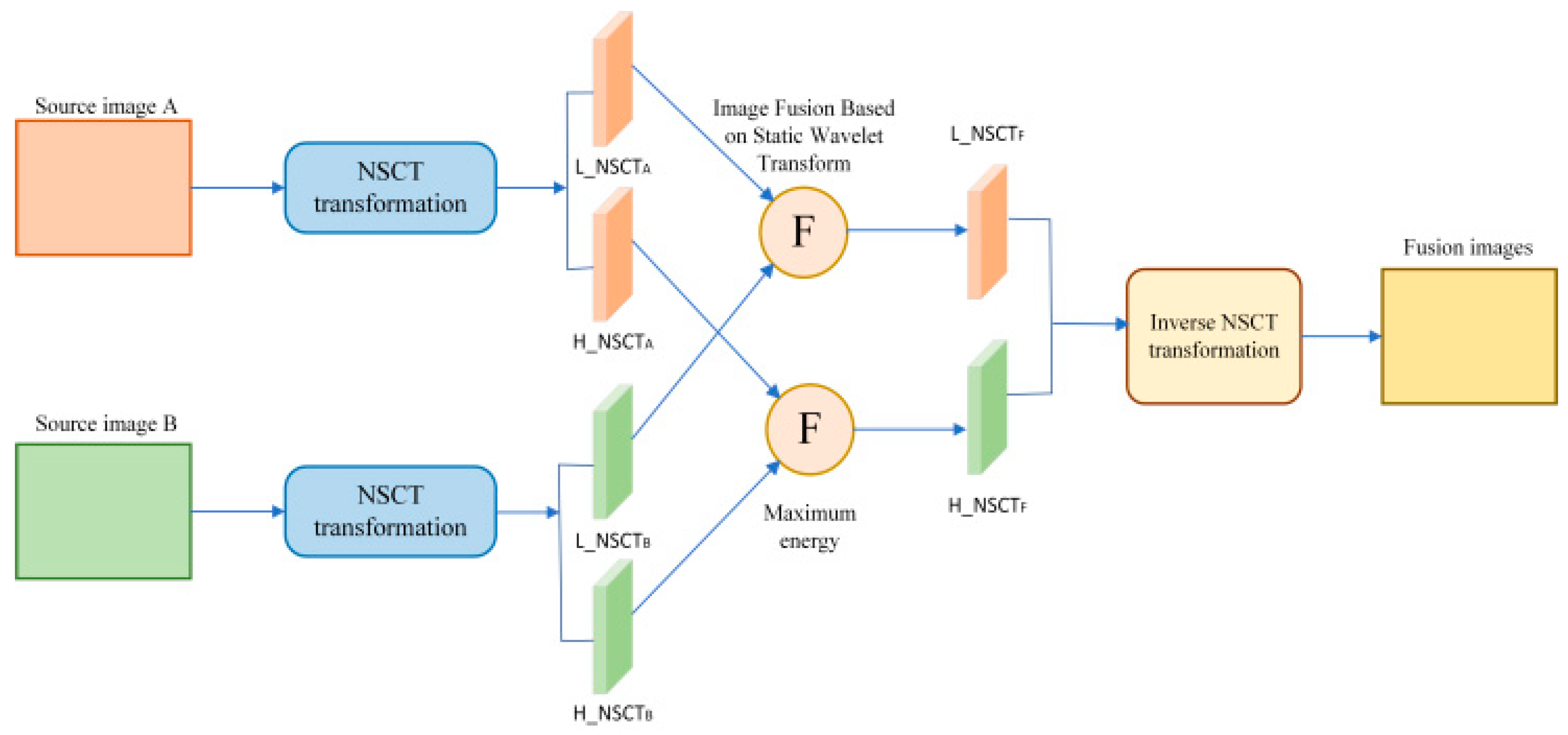
The SWT is a classic shift-invariant wavelet transform that captures detailed information of images [17]; however, it lacks the ability to describe edge information. On the other hand, NSCT is a flexible multi-scale and multidirectional image decomposition method [18] that can extract geometric structural features of images, but it has limitations in capturing fine details. Therefore, this system leverages the complementary characteristics of SWT and NSCT for road surface image fusion, generating fused road surface images, as illustrated in Figure 8. This approach not only enriches the fused images with more detailed textural features, thereby improving image quality, but also enhances edge and shape features, ultimately increasing the clarity of the fused images.
When wavelet transform is applied to image processing, let φ(x) and φ(y) be one-dimensional scaling functions. The two-dimensional scaling function φ(x, y) = L2(R2) is expressed as φ(x, y) = φ(x)φ(y). Let Ψ(x) and Ψ(y) be one-dimensional wavelet functions, respectively; the two-dimensional dyadic wavelets are expressed as
Ψ1 (x, y) = φ(x)Ψ (y)
Ψ2 (x, y) = Ψ (x)φ(y)
Ψ3 (x, y) = Ψ (x)Ψ (y)
It can be known from the above three transformation forms that the two-dimensional wavelet function is decomposed into the product of two one-dimensional functions. This structural characteristic is called a two-dimensional separable wavelet function. In specific applications, high-pass or low-pass filters matched with the wavelet function can effectively extract the required frequency components from the input signal. During the wavelet transform process, by eliminating downsampling and performing upsampling operations, the problem of the wavelet coefficients lacking translation invariance is solved, and the effect of image information extraction is improved at the same time.
The contourlet transform is a multi-resolution and multidirectional transform that allows for a different number of directions at each scale. Due to the downsampling operations performed in the two stages of Laplacian Pyramid (LP) and Directional Filter Bank (DFB), the redundancy of image Contourlet coefficients is significantly reduced. However, this also results in the transform lacking translation invariance, leading to image distortion. In contrast, the nonsubsampled contourlet transform (NSCT) adopts a nonsubsampled pyramid decomposition and a directional filter bank, which solves problems such as the lack of translation invariance and the Gibbs phenomenon.
The NSCT consists of two main steps: first, multi-scale decomposition of the image is achieved by removing downsampling and upsampling the filters. When the number of decomposition levels is J, the redundancy of the nonsubsampled pyramid decomposition is J + 1, which satisfies the Bezout identity for perfect reconstruction:
H0(z)G0(z) + H1(z)G1(z) = 1
Among them, H0(z) and G0(z) are the low-pass decomposition filter and the low-pass synthesis filter, respectively, while H1(z) and G1(z) are the high-pass decomposition filter and the high-pass synthesis filter, respectively.
Subsequently, all filters are derived from a single fan filter to implement the nonsubsampled directional filter bank, which satisfies the Bezout identity:
U0(z)V0(z) + U1(z)V1(z) = 1
Among them, U0(z) and V0(z) are the low-pass decomposition filter and synthesis filter of the directional filter bank, respectively, while U1(z) and V1(z) are the high-psass decomposition filter and synthesis filter of the directional filter bank, respectively.
The specific steps of the road surface image fusion algorithm are as follows:
Step 1
Perform nonsubsampled contourlet transform (NSCT) decomposition on the two preprocessed images, A and B, with their sub-band coefficients denoted as NSCTA{s,d} and NSCTB{s,d}, respectively. where s = 0, 1, …, S and d = 1, 2, …, 2n. Here, S represents the number of decomposed sub-bands, and 2n denotes the total number of directions in each sub-band. NSCTA{s,d} and NSCTB{s,d} correspond to the low-frequency sub-bands.
Step 2
Select pixels with higher energy values for fusion. The window size is 5 × 5, i.e.,
W = 1 256 4 4 4 4 4 4 16 16 16 4 4 16 64 16 4 4 16 16 16 4 4 4 4 4 4
The calculation formula for pixel energy is
E N S C T ( i , j ) = m = 2 2 n = 2 2 s = 2 S d = 1 D W ( m + 3 , n + 3 ) N S C T ( s , d ) ( i + m , j + n )
where S represents the total number of scales, and D denotes the total number of directional frequencies. The selection rule for fusion coefficients is as follows:
N S C T F ( s , d ) = N S C T A ( s , d ) , E A N S C T > E B N S C T N S C T B ( s , d ) , o t h e r
Step 3
For the low-frequency coefficients NSCTA{0,1} and NSCTB{0,1}, image fusion is performed using the stationary wavelet transform (SWT). The algorithm is as follows:
(a)
Apply a three-level stationary wavelet decomposition to the two low-frequency coefficients to obtain the corresponding wavelet coefficients.
(b)
Fuse the low-frequency coefficients in the transform domain using a weighted averaging operator.
F L L = w A L L + ( 1 w ) B L L
Then, w = 0.5.
(c)
The high-frequency transform coefficients are fused using the pixel energy maximum method. The regional characteristics of the pixels are captured through the high-frequency sub-band window W within each scale, and the significance of the coefficients is comprehensively evaluated. The calculation formula is as follows:
E S W T ( i , j ) = m = 2 2 n = 2 2 S = 2 L d = 1 K W ( m + 3 , n + 3 ) S W T ( l , k ) ( i + m , j + n )
where S is the total number of scales and D is the total number of orientations. The coefficients in the transform domain are selected according to the following principles.
S W T F ( l , k ) = S W T A ( l , k ) , E A S W T > E B S W T S W T B ( l , k ) , o t h e r
(d)
Perform an inverse stationary wavelet transform on the fused multi-resolution image to obtain the fused image NSCTF{0,1}. Finally, Execute an inverse nonsubsampled contourlet transform on the NSCTF{s,d} of the road surface fusion image to generate the final fused road surface image.
Image registration is the process of estimating image similarity by matching the feature relationships between images and is a core step in image fusion. Typically, an image rich in features is selected as the reference, and the target image is projected onto the reference image plane to ensure alignment in the same coordinate system. Intermediate images are often used as reference images during registration to reduce the accumulation of errors. Registration challenges mainly arise from differences in the imaging conditions. Currently, most image-registration algorithms are based on image features, with point-feature-based registration offering high accuracy and effectiveness. Therefore, the selection of point features is crucial for image registration. The SIFT (scale-invariant feature transform) [19] algorithm, which is known for its scale and spatial invariance, can adapt to images under varying exposure and acquisition conditions. In addition, its rich feature point information makes it suitable for fast and accurate image registration. Thus, this system uses an SIFT-based point-feature image registration algorithm to estimate image similarity.
Subjective quality evaluation criteria for image fusion include absolute and relative evaluations. The former involves observers directly assessing the quality of fused images, whereas the latter requires observers to classify and compare fused images generated by different methods before providing scores. Although subjective evaluation is simple and intuitive, it is prone to interference from subjective factors and faces challenges in practical applications that often lack precision. Therefore, objective quality evaluation methods for image fusion are required.
Objective quality evaluation metrics, such as spatial frequency (SF), mutual information (MI), root mean square error (RMSE), and QAB/F, are employed to effectively and comprehensively evaluate the performance of image fusion algorithms in road-surface image fusion. Higher values of SF, MI, and QAB/F indicate greater clarity, richer information, and better fusion performance in the fused images. Conversely, a lower RMSE value indicates a better quality of the fused images.
The definition of SF is given by
S F = ( R F ) 2 + ( C F ) 2 ,
In the equation, RF represents row frequency, and CF represents column frequency. A higher value indicates greater clarity of the fused image.
MI measures the amount of information transferred to the fused image. The mutual information between the source image A and the fused image F is given by
M I A , F = i = 1 L J = 1 L h A , F ( i , j ) log 2 h A , F ( i , j ) h A ( i ) h F ( j ) ,
In the equation, hA,F(i,j) represents the normalized joint gray-level histogram of Images A and F, hA(i) and hF(i) are the normalized histograms of the two images, and L is the number of gray levels. The mutual information between the source image B and the fused image F can be denoted as MIB,F. The image fusion result is thus expressed as
M I = M I A , F + M I B , F ,
A higher MI value indicates a better quality of the fused image.
RMSE between the actual fused image F and the ideal fused image R is defined as
R M S E = 1 M N i = 1 M i = 1 N [ R ( i , j ) F ( i , j ) ] 2 ,
A smaller value indicates a better quality of the fused image.
The QAB/F calculates the edge strength information g(n, m) and orientation information a(n, m) in the source images A and B, as well as the fused image F, using the Sobel edge detection operator. For image A,
g A ( n , m ) = s A x ( n , m ) 2 + s A y ( n , m ) 2
a ( n , m ) = tan 1 S A x ( n m ) S A y ( n m )
where sAx (n,m) and sAy (n, m) are the outputs of the vertical Sobel template and the horizontal Sobel template, respectively, convolved with the source image centered at pixel PA(n,m). The related strength information G n , m A F and the related orientation information A n , m A F between the source image A and the fused image F are expressed as follows:
G n , m A F , A n , m A F = g n , m F g n , m A M , 1 α A ( n , m ) α F ( n , m ) π / 2
M = 1 , g A ( n , m ) > g F ( n , m ) 1 , o t h e r
Q n , m A F = Γ g Γ α 1 + e k g G n , m A F σ g 1 1 + e k g A n , m A F σ α 1 Q A B / F = n , m Q n , m A F w n , m A + Q n , m A F w n , m B w n , m A + w n , m B
where the weights w n , m A = [ g A ( n , m ) ]L and w n , m B = [ g B ( n , m ) ]L, with L being a constant set to 1.
A higher QAB/F value indicates that the fused image retains richer edge information from the source images.
3. Experimental Evaluation

3.1. Road Surface Image Acquisition Experiment

The experiment was carried out using an image acquisition vehicle equipped with a high-speed road surface image acquisition system on an unobstructed smooth road section. The performance of the system was evaluated by continuously recording acquired road surface images in various speed ranges, followed by an analysis of the results. The aim was to analyze the acquisition results and demonstrate the feasibility of the hybrid anti-shake technology in the stabilization module of the system.
The high-speed acquisition of pavement images was conducted on unobstructed and smooth road segments. Pavement images continuously captured at various speed intervals of the system were recorded, and the results were evaluated and analyzed. In the image acquisition module of the system, the OV2710 binocular image sensors were vertically oriented toward the road surface, with a separation of 1.5 cm between the two sensors and a height of 25 cm above the pavement. The image reception device was placed inside the trunk of the acquisition vehicle to receive real-time high-speed pavement images, and all modules were debugged to ensure normal system operation.
The high-speed acquisition experiment was divided into two phases. In the first phase, continuous pavement images were captured at speeds of 20 km/h, 40 km/h, and 60 km/h, respectively. For each speed interval, images were acquired over a distance of 500 m, with a frame rate of 120 FPS and an exposure time of 7.3 ms. Assuming the field of view width of the acquired images is Wt and the height is H, the formula for calculating the field of view range of the system’s image acquisition is as follows:
A = Wt × H
The field of view height H of the images acquired by the system is calculated as follows:
H = D   ×   t a n a 2
where D denotes the height of the image sensor above the ground, and a represents the vertical field of view angle, calculated as follows:
a = 2 a r c t a n h 2 f
where h is the height of the image sensor, and f is the focal length of the image sensor.
The field of view width Wt of the system’s acquired images is calculated as follows:
Wt = 2W + d
where Wt denotes the total field of view width, and W represents the field of view width of a single sensor.
W = H × P
where P is the aspect ratio of the image sensor, H is the field of view height of the image sensor, and d is the distance between the two sensors.
Based on the aforementioned analysis and calculations, the field of view range for high-speed image acquisition by the system is determined to be 63 cm × 30.75 cm. After confirming the system’s capability to capture clear pavement images at 60 km/h, the image acquisition module was calibrated to ensure operational stability. The system subsequently proceeded to continuously capture high-speed pavement images at 80 km/h, 100 km/h, and 120 km/h, with each speed segment covering a distance of 500 m.
Upon achieving clear image acquisition at 120 km/h, the collection vehicle continued to accelerate in increments of 5 km/h. The captured pavement images were observed, and the motion blur value was calculated for each speed segment. When the motion blur value exceeds 1, it leads to image quality degradation and visible blurring phenomena. Given the collection vehicle’s speed v and the image sensor’s exposure time t, the motion blur value is calculated as follows:
x = vtβ
where β is the image magnification ratio, set to 4.
Table 2 lists the number of road surface images acquired by the system for each speed range.
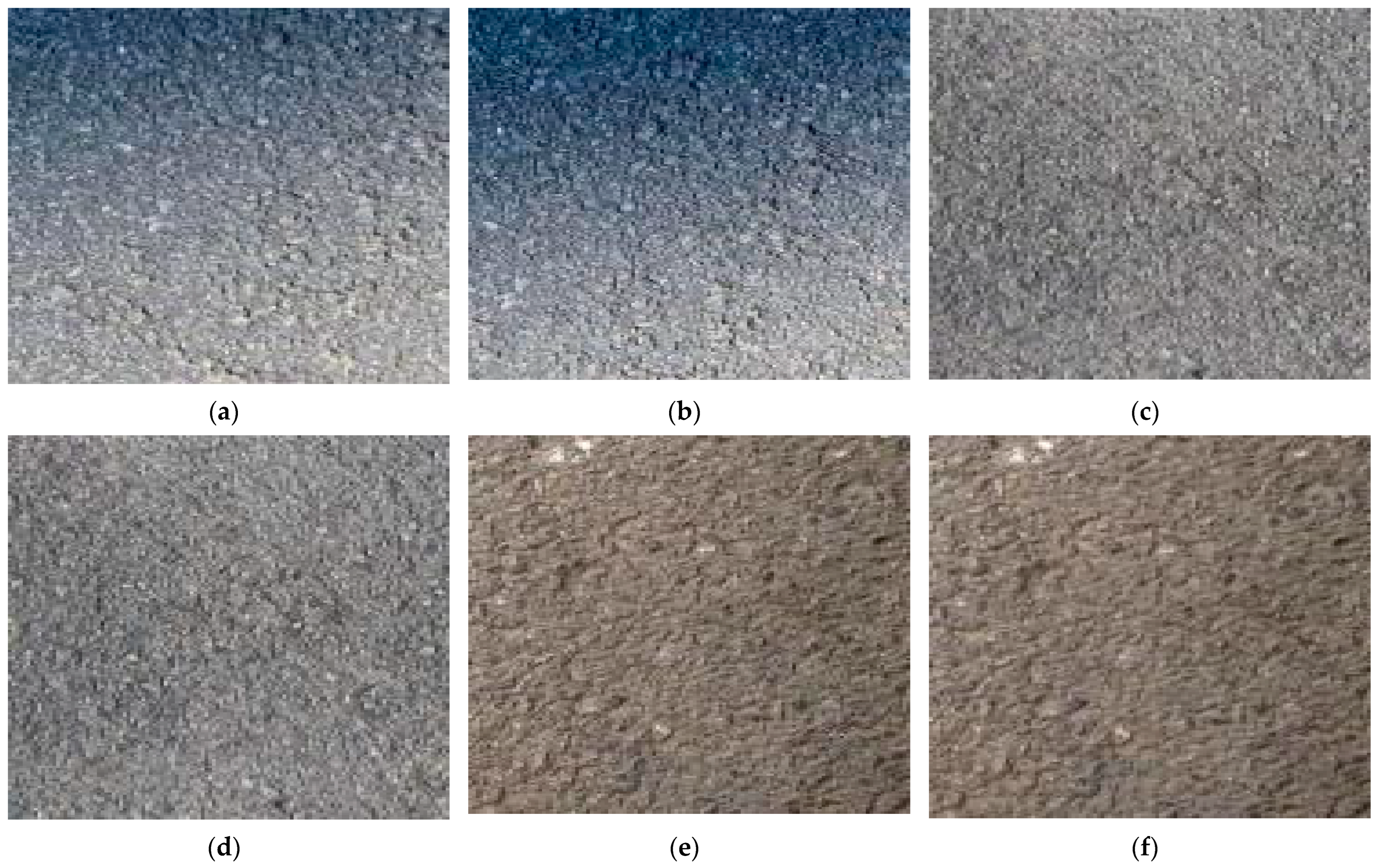
As shown in Figure 9, during the first phase of the acquisition experiment, the system continuously acquired road surface images at speeds of 20, 40, and 60 km/h. It could be observed that the quality of the road surface images acquired at these three speeds was good, with no blur, indicating that both the hardware fixation device and the electronic stabilization system effectively compensated for motion during high-speed acquisition, ensuring system stability. The high-speed acquired road surface images were first cached and processed in the DDR3 SDRAM of the FPGA hardware platform and then transmitted in real time to the PC via HDMI for display. The calculated motion blur values for the road surface images at 20 km/h, 40 km/h, and 60 km/h were 0.1620, 0.3244, and 0.4864, respectively, all of which were less than 1, indicating a good quality of the acquired images with no loss of detailed information.
Figure 10 shows the binocular road surface images acquired by the system at high speeds of 80, 100, and 120 km/h. Table 3 presents the clarity of the road surface images acquired by the system at speeds ranging from 20 km/h to 120 km/h.
As shown in Table 3 and Figure 10, the road surface images acquired by the system at 80, 100, and 120 km/h had no blur and demonstrated good clarity, with values close to 1. The calculated motion blur values for these speeds are 0.6488, 0.8108, and 0.9732, respectively, all of which are less than 1. Therefore, the system meets the design requirements for high-speed road surface image acquisition. When the acquisition vehicle reached a speed of 125 km/h, localized blur began to appear in the images with a significant loss of detailed information. The calculated motion blur value was 1.013 and the clarity was 0.3450, which was far from 1. At this speed, the system was unable to acquire clear images. This indicates that the system can acquire clear road surface images with a resolution of 640 × 480 pixels at a speed of 120 km/h.
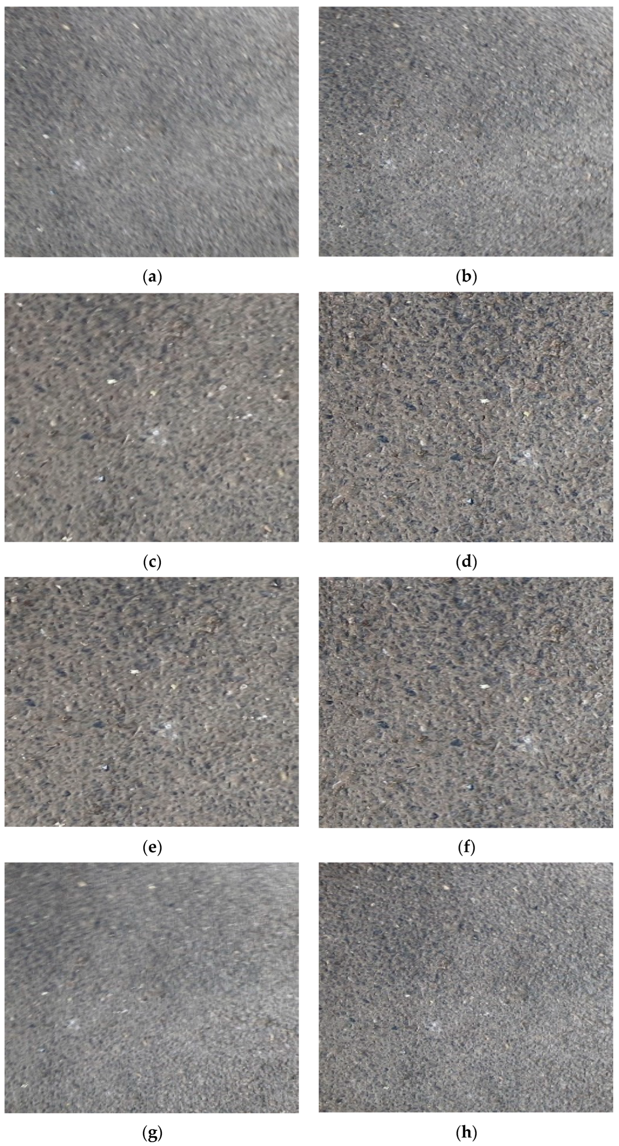
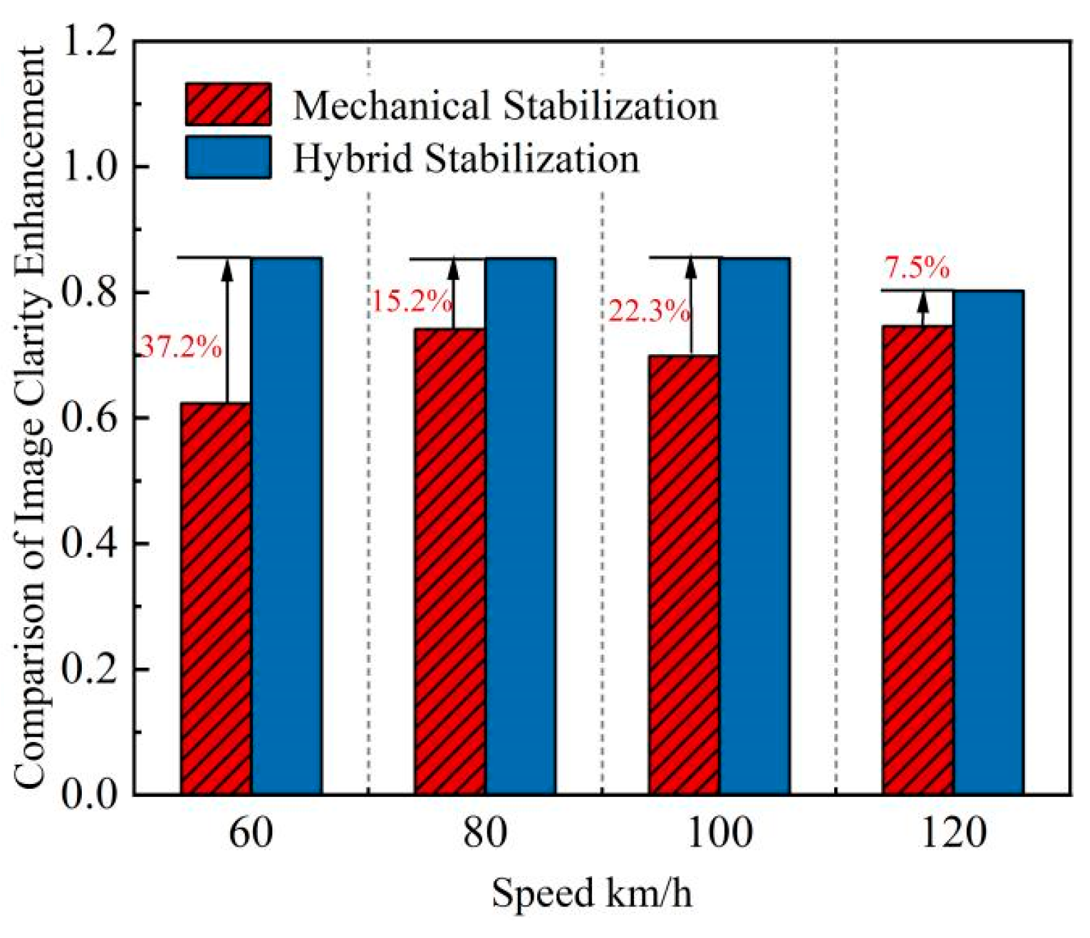
To compare the image clarity effects of the traditional mechanical stabilization methods and hybrid stabilization technology during high-speed acquisition, high-speed road surface images acquired at 60, 80, 100, and 120 km/h were analyzed. The results of the image clarity enhancement using the two methods are compared in Figure 11.
As shown in Figure 11 and Figure 12, the hybrid stabilization technology demonstrated superior performance in enhancing the clarity of high-speed images. The image clarity at speeds ranging from 60 to 120 km/h was consistently higher than that achieved with traditional mechanical stabilization methods, with improvements of 37.2%, 15.2%, 22.3%, and 7.5%, respectively. This technology can process and compensate for image jitter in real time during high-speed acquisition, offering high precision and effective stabilization. Therefore, the adoption of hybrid stabilization technology in the image clarity enhancement module of this system is feasible.

3.2. Road Surface Image Fusion Results and Analysis

To compare the proposed image fusion method based on SWT and NSCT with the results of using SWT and NSCT individually for road surface image fusion, the fusion algorithm was analyzed. After preprocessing the road surface images through registration, the two images were aligned in the same coordinate system. OV1 and OV2, two sets of road surface images acquired by the binocular acquisition system at speeds of 20, 40, 60, 80, 100, and 120 km/h, were fused using SWT and NSCT, respectively. Table 4 and Table 5 present the quality evaluations of the fused road surface images using the SWT and NSCT at speeds ranging from 20 to 120 km/h, respectively.
As shown in Table 4 and Table 5, the evaluation metric QAB/F for the road surface image fusion results using SWT was higher than that of NSCT, whereas the evaluation metric SF for the road surface image fusion results using NSCT was higher than that of SWT.
As shown in Table 6, after the road surface images acquired by the system at high speeds ranging from 20 km/h to 120 km/h were processed using SWT and NSCT fusion, the image clarity was improved compared with using SWT or NSCT individually, demonstrating better fusion results. As illustrated in Figure 13, by comparing the changes in the quality metrics before and after image fusion across different speed ranges, it is evident that the introduced road surface image fusion algorithm based on SWT and NSCT results in an increase in the QAB/F, SF, and MI metrics after fusion. Specifically, at 100 km/h, the SF value increased by 2.821 and the MI value increased by 3.044 after fusion at 120 km/h.
As shown in Figure 14, to compare the performance of the three image fusion algorithms, road surface images acquired at four speed ranges—60, 80, 100, and 120 km/h—were used as examples to analyze the quality evaluation results after image fusion using the three algorithms. The fusion results of the road surface image fusion algorithm based on SWT and NSCT outperformed the other two algorithms. Specifically, at 80 km/h, the SF value is 4.5, which is higher than that of the SWT and 4.412 higher than that of the NSCT, indicating that the fused images are clearer. The increase in QAB/F and MI values suggests that the fused images retain richer edges and detailed information, making the image content more comprehensive. This method achieved excellent results when fusing road surface images. Therefore, the image fusion method based on stationary wavelet transform and nonsubsampled contourlet transform is suitable for enhancing the clarity of road surface images and capturing detailed edge information.

4. Conclusions

Based on binocular vision, the high-speed road surface image acquisition system designed in this study features low cost, low power consumption, real-time performance, and high accuracy. It is capable of acquiring stable, clear, and detailed road surface images under high-speed conditions. By employing a hybrid anti-shake technology combining mechanical and electronic stabilization, the system effectively reduces the impact of vibrations on image quality, enhancing the accuracy and reliability of high-speed acquisition. Subsequently, an image fusion algorithm based on stationary wavelet transform and nonsubsampled contourlet transform is applied to enrich the image information and improve clarity. The conclusions are as follows:
(1)
The external mechanical stabilization of the hardware device of the system uses an acrylic plate with a dimension of 114.5 mm × 156.5 mm × 17 mm and a thickness of 2 mm to securely install the system at the rear of the high-speed acquisition vehicle. An electronic stabilization algorithm was designed in the system to compensate for the horizontal, vertical, and rotational motion vectors of the images in real time. The system continuously acquired road surface images at speeds ranging from 20 to 120 km/h, totaling 26,480 images. The field of view for the image acquisition was 63 cm × 30.75 cm. An evaluation method for image clarity and information richness was established to analyze and assess the acquisition results. The results indicate that the system can achieve the continuous acquisition of clear road surface images with a resolution of 640 × 480 at a speed of 120 km/h.
(2)
To address the issues of insufficient clarity and information richness in high-speed acquired images, a road surface image fusion algorithm based on stationary wavelet transform and nonsubsampled contourlet transform was introduced. This algorithm leverages the complementary characteristics of multi-scale and multidirectional analyses to preserve the edge and detail information in the images. The results show that the road surface image fusion algorithm based on the stationary wavelet transform and nonsubsampled contourlet transform outperforms the fusion algorithms using SWT or NSCT individually in terms of quality evaluation metrics such as QAB/F, SF, MI, and RMSE. At 80 km/h, the SF value is 4.5, which is higher than that of the SWT and 4.412 higher than that of the NSCT, indicating that the fused images are clearer. The increase in QAB/F and MI values demonstrates that the fused road surface images retain rich edges and detailed information, achieving excellent results in image fusion.
In summary, for the high-speed road surface image acquisition system designed in this study, a hybrid anti-shake technology that combines mechanical hardware and electronic stabilization is proposed. This approach comprehensively enhances the system stability and image quality during both the image acquisition and processing stages, enabling the acquisition of stable, clear, and detailed road surface images under high-speed conditions. Additionally, this study is the first to apply SWT + NSCT fusion to road surface images, providing new insights into multimodal perception and further demonstrating the feasibility and superiority of the proposed system. This offers a reliable theoretical foundation for road maintenance management departments and provides significant engineering guidance for the effective implementation of maintenance management methods. Future research will focus on AI-driven intelligence to enhance the intelligence, computational efficiency, and adaptability of the system. For instance, by integrating the real-time capabilities of electronic stabilization with the intelligent advantages of AI, more robust anti-shake solutions can be developed. Through the introduction of more advanced AI algorithms, the system can achieve high-precision and high-efficiency road surface image acquisition and processing in more complex traffic environments. Furthermore, by optimizing heterogeneous computing architectures, such as exploring FPGA + GPU heterogeneous computing, we will support higher frame rates for real-time processing, driving the intelligent and efficient development of traffic systems.

Author Contributions

Conceptualization, Z.D. and R.G.; methodology, Z.D.; software, Z.D.; validation, Z.D., Q.J., and Y.M.; formal analysis, Y.W.; investigation, Z.D.; resources, Y.W.; data curation, R.G.; writing—original draft preparation, Z.D. and R.G.; writing—review and editing, Y.W. and R.G.; visualization, Z.D.; supervision, R.G.; project administration, R.G.; funding acquisition, R.G. All authors have read and agreed to the published version of the manuscript.

Funding

This research was funded by National Natural Science Foundation of China grant number No. 52305212 and China Postdoctoral Science Foundation funded project grant number No. 2021M692516; 2024T170715.

Data Availability Statement

The data used to support the findings of this study are included within the article.

Conflicts of Interest

The authors declare no conflicts of interest.

References

  1. Zhang, H.; Dong, Y.; Hou, Y.; Cheng, X.; Xie, P.; Di, K. Research on asphalt pavement surface distress detection technology coupling deep learning and object detection algorithms. Infrastructures 2025, 10, 72. [Google Scholar] [CrossRef]
  2. Chen, H.; Wen, X.; Liu, Y.; Zhang, H. Research on comprehensive vehicle information detection technology based on single-point laser ranging. Sensors 2025, 25, 1303. [Google Scholar] [CrossRef] [PubMed]
  3. Li, Q.; Li, B.; Mao, Q.; Hu, Q.; Geng, X.; Li, J. Research on intelligent pavement inspection vehicle. In Proceedings of the 2005 Annual Meeting of China Highway Society (I), Xinjiang, China, 18 August 2005; pp. 203–209. [Google Scholar]
  4. Zhang, X.H.; Hong, H.Y.; Hou, J.; Jing, G. Research on real-time detection method for pavement distress images. Electron. Des. Eng. 2009, 17, 36–37,40. [Google Scholar]
  5. Liu, J. Research on the application of CiCS road detection vehicle in asphalt pavement detection. China High. New Technol. 2023, 21, 108–110. [Google Scholar] [CrossRef]
  6. Youla, D.C.; Webb, H. Image restoration by the Method of convex projections. IEEE Trans. Med. Imaging 1982, 2, 81–94. [Google Scholar] [CrossRef] [PubMed]
  7. Glasner, D.; Bagon, S.; Irani, M. Super-resolution from a single image. In Proceedings of the IEEE International Conference on Computer Vision, Kyoto, Japan, 29 September–2 October 2009; pp. 349–356. [Google Scholar]
  8. Dong, C.; Loy, C.C.; He, K.; Tang, X. Image super-resolution using deep convolutional networks. IEEE Trans. Pattern Anal. Mach. Intell. 2016, 38, 295–307. [Google Scholar] [CrossRef] [PubMed]
  9. Zhang, K.; Zuo, W.; Chen, Y.; Meng, D.; Zhang, L. Beyond a gaussian denoiser: Residual learning of deep CNN for image denoising. IEEE Trans. Image Process. 2017, 26, 3142–3155. [Google Scholar] [CrossRef] [PubMed]
  10. Chen, C.; Chen, Q.; Xu, J.; Koltun, V. Learning to see in the Dark. In Proceedings of the IEEE/CVF Conference on Computer Vision and Pattern Recognition, Salt Lake City, UT, USA, 18–22 June 2018; pp. 3291–3300. [Google Scholar] [CrossRef]
  11. Wang, Y.; Chen, C.X.; Zhang, Y.G.; Guo, L.; Shen, P. Image clarity enhancement method based on generative adversarial Network. Mod. Comput. 2022, 28, 64–68. [Google Scholar]
  12. Liu, C.; Jing, Z.; Xiao, G.; Yang, B. Feature-based fusion of infrared and visible dynamic images using target detection. Chin. Opt. Lett. 2007, 5, 274–277. [Google Scholar]
  13. Goshtasby, A.A.; Nikolov, S. Image fusion: Advances in the state of the art. Inf. Fusion 2007, 8, 114–118. [Google Scholar] [CrossRef]
  14. Dai, Y.; Bai, Y.; Zhang, W.; Chen, X. Effectiveness evaluation of hardware design based on vivado HLS. Comput. Knowl. Technol. 2021, 17, 1–4. [Google Scholar] [CrossRef]
  15. Zhan, C.; Long, W.; Ding, Y.; Li, F. Design of multi channel data collection and processing system based on FPGA. J. Shenzhen Univ. (Sci. Eng.) 2016, 3, 127–133. [Google Scholar] [CrossRef]
  16. Yu, S.; Zhang, H.; Peng, L.; Luo, Y. Evaluation algorithm of non-reference image quality applying re-fuzzy theory. Transducer Microsyst. Technol. 2021, 40, 140–143. [Google Scholar] [CrossRef]
  17. Nason, G.P.; Silverman, B.W. The stationary wavelet transform and some statistical applications. In Wavelets and Statistics; Antoniadis, A., Oppenheim, G., Eds.; Springer: New York, NY, USA, 1995; pp. 281–299. [Google Scholar] [CrossRef]
  18. Da Cunha, A.L.; Zhou, J.; Do, M.N. The nonsubsampled contourlet transform: Theory, design, and applications. IEEE Trans. Image Process. 2006, 15, 3089–3101. [Google Scholar] [CrossRef] [PubMed]
  19. Khan, N.Y.; McCane, B.; Wyvill, G. SIFT and SURF performance evaluation against various image deformations on benchmark dataset. In Proceedings of the International Conference on Digital Image Computing: Techniques and Applications, Noosa, QLD, Australia, 6–8 December 2011; pp. 501–506. [Google Scholar] [CrossRef]
Figure 1. System architecture diagram.
Asi 08 00173 g001
Figure 2. System physical diagram.
Asi 08 00173 g002
Figure 3. Acrylic protective board.
Asi 08 00173 g003
Figure 4. System fixing position diagram.
Asi 08 00173 g004
Figure 5. Schematic diagram of motion vector estimation.
Asi 08 00173 g005
Figure 6. (a) The high-speed road surface images before electronic image stabilization processing; (b) the high-speed road surface images after electronic image stabilization processing.
Asi 08 00173 g006
Figure 7. (a) The horizontal component of jitter in high-speed road surface images; (b) the vertical component of jitter in high-speed road surface images; (c) the rotational component of jitter in high-speed road surface images.
Asi 08 00173 g007
Figure 8. Framework diagram of image fusion based on SWT and NSCT.
Asi 08 00173 g008
Figure 9. (a,b) Binocular road surface images acquired by the system at speeds of 20 km/h; (c,d) binocular road surface images acquired by the system at speeds of 40 km/h; (e,f) binocular road surface images acquired by the system at speeds of 60 km/h.
Asi 08 00173 g009
Figure 10. (a,b) Binocular road surface images acquired by the system at speeds of 80 km/h; (c,d) binocular road surface images acquired by the system at speeds of 100 km/h; (e,f) binocular road surface images acquired by the system at speeds of 120 km/h.
Asi 08 00173 g010
Figure 11. (a,b) Mechanical stabilization and hybrid stabilization at 60 km/h; (c,d) mechanical stabilization and hybrid stabilization at 80 km/h; (e,f) mechanical stabilization and hybrid stabilization at 100 km/h; (g,h) mechanical stabilization and hybrid stabilization at 120 km/h.
Asi 08 00173 g011
Figure 12. Bar chart comparing image clarity of two stabilization methods.
Asi 08 00173 g012
Figure 13. Bar chart comparing road surface image fusion results before and after using SWT and NSCT: (a) QAB/F; (b) SF; (c) MI; (d) RMSE.
Asi 08 00173 g013
Figure 14. Quality evaluation results of image fusion using different algorithms: (a) 60 km/h; (b) 80 km/h; (c) 100 km/h; (d) 120 km/h.
Asi 08 00173 g014
Table 1. Comparison of common camera parameters.
Interface TypeMIPICSI-2USB3.0DVP
Transmission ModeSerial
Transmission
Serial
Transmission
Parallel
Transmission
Transmission Bandwidth5 Gbps5 Gbps96 Mps
Anti-Interference Capability200 mV
Differential
Signal
400 mV
Differential
Signal
Relatively
Weak
Interface TypeMIPICSI-2USB3.0DVP
Compatible CamerasAbove
800 W
500 W500 W
Table 2. Image acquisition table.
Acquisition Speed km/hAcquisition Time/sNumber of Acquired Images
Asi 08 00173 i00190.1210,815
Asi 08 00173 i00245.025400
Asi 08 00173 i00330.023602
Asi 08 00173 i00422.512701
Asi 08 00173 i00518.012162
Asi 08 00173 i006
total
15
220.68
1800
26,480
Table 3. Clarity of road surface images acquired by the system at speeds of 20 km/h to 120 km/h.
Acquisition Speed km/hClarity/S
200.9032
400.8554
600.7998
800.8001
1000.7954
1200.8321
Table 4. Quality evaluation of road surface fusion images using SWT.
Acquisition Speed km/hQAB/FSFMIRMSE
Before Fusion
After Fusion
Before Fusion
After Fusion
Before Fusion
After Fusion
Before Fusion
After Fusion
200.5970.6257.625 7.8046.327 6.7022.631 2.365
400.7060.7327.352 7.6356.524 6.7972.325 2.155
600.6810.6977.541 7.8037.101 7.3092.012 1.985
800.795 0.8068.012 8.3027.993 8.1052.142 2.211
1000.872 0.8818.124 8.2537.741 7.8741.965 1.894
1200.885 0.8938.324 8.4657.352 7.4942.754 2.698
Table 5. Quality evaluation of road surface fusion images using NSCT.
Acquisition Speed km/hQAB/FSFMIRMSE
Before Fusion
After Fusion
Before Fusion
After Fusion
Before Fusion
After Fusion
Before Fusion
After Fusion
200.514 0.5537.472 7.9096.745 7.1021.584 1.432
400.632 0.6487.129 7.6325.997 6.6541.465 1.245
600.732 0.7417.836 8.0265.952 6.3541.852 1.720
800.597 0.6407.623 8.1906.014 6.9631.857 1.500
1000.475 0.5928.551 8.960 6.854 7.4941.584 1.491
1200.654 0.8788.129 8.6566.587 7.303 1.962 1.608
Table 6. Quality evaluation of road surface fusion images based on SWT and NSCT.
Acquisition Speed km/hQAB/FSFMIRMSE
200.8358.9246.8021.652
400.8629.3256.8321.951
600.7678.1937.4971.224
800.96612.6029.1251.012
1000.90110.9638.6811.326
1200.9139.9657.6261.501
Disclaimer/Publisher’s Note: The statements, opinions and data contained in all publications are solely those of the individual author(s) and contributor(s) and not of MDPI and/or the editor(s). MDPI and/or the editor(s) disclaim responsibility for any injury to people or property resulting from any ideas, methods, instructions or products referred to in the content.