Article

A QR-Enabled Multi-Participant Quiz System for Educational Settings with Configurable Timing

1
Key Laboratory of Space Utilization, Technology and Engineering Center for Space Utilization, Chinese Academy of Sciences, Beijing 100094, China
2
University of Chinese Academy of Sciences, Beijing 100049, China
3
College of Information Science and Engineering, Lanzhou University, Lanzhou 730000, China
*
Authors to whom correspondence should be addressed.
These authors contributed equally to this work.
Appl. Syst. Innov. 2025, 8(6), 158; https://doi.org/10.3390/asi8060158
Submission received: 19 September 2025 / Revised: 14 October 2025 / Accepted: 17 October 2025 / Published: 22 October 2025

Abstract

An integrated QR-based identification and multi-participant quiz system is developed for classroom and competition scenarios. It reduces the check-in latency, removes fixed buzz-in timing, and lifts hardware-imposed limits on the participant count. On the software side, a MATLAB-R2022b-based module integrates the generation and recognition of linear barcodes and QR Codes, enabling fast, accurate acquisition of contestant information while reducing the latency and error risk of manual entry. On the hardware side, control circuits for compulsory and buzz-in modules are designed and simulated in Multisim-14.3. To accommodate diverse scenarios, the team-versus-team buzz-in mode is extended to support two- or three-member teams. Functional tests demonstrate the stable display of key states—including contestant identity, buzz-in priority group ID, and response duration. Compared with typical MCU-channel-based designs, the proposed system relaxes hardware-channel constraints, decoupling the participant count from fixed input channels. It also overcomes fixed-timing limitations by supporting scenario-dependent configuration. The Participant Information Registration subsystem achieved a mean accuracy of 86.7% and a mean per-sample computation time of 14 ms. The 0–99 s configurable timing aligns with question difficulty and instructional procedures. It enhances fairness, adaptability, and usability in formative assessments and competition-based learning.

1. Introduction

As digital transformation accelerates, Quick Response (QR) Codes—with high information density, built-in error correction [1], robustness to contamination and occlusion [2], and strong extensibility—have been deployed at scale for product traceability [3], e-ticketing, mobile payments, and scholarly resource management [4], forming a mature coding and implementation ecosystem [5]. Additionally, the technology is highly portable and imposes minimal deployment barriers in educational settings [6]. In contrast, competitive events still rely on manual data collection and fixed-function hardware [7], leading to low check-in throughput (≈15–30 s/person) and elevated entry errors (≈3–5%) [8]. In educational settings—such as classroom interactions and course competitions—these bottlenecks undermine instructional efficiency, degrade interaction quality, and compromise the verifiability of adjudication [9,10]. Concurrency is inadequate, and fairness is difficult to quantify or guarantee. For the check-in stage, approaches based on Radio Frequency Identification (RFID)/Near Field Communication (NFC) [11], mobile apps [12,13], and face recognition encounter practical constraints in cost [14], privacy compliance, network/terminal dependencies, and deployment complexity. In school and training settings, attendance/sign-in platforms are often constrained by device heterogeneity and limited network availability. As a result, they provide poor support for offline operation and concurrent instruction across multiple classrooms [15,16]. For in-event interaction (e.g., buzz-in/answering), prevailing systems adopt a Microcontroller Unit (MCU) channel-based architecture of which concurrency is structurally limited by I/O resources and instruction cycles. Coupled with fixed Resistor/Capacitor (RC) timing that lacks configurability and temporal stability [17,18], such designs are ill-suited to diverse question types and rule sets [19,20]. In educational practice, these limitations hinder formative assessments and fair decision-making. They also restrict the adoption of instructional designs such as team-based learning and differentiated instruction [21,22]. Accordingly, a systematic approach is required to balance recognition accuracy, concurrent scalability, configurable timing, and implementation economy.
To address these issues, a robust QR-Code-recognition pipeline is constructed for check-in and identity binding. It comprises image preprocessing (denoising and adaptive thresholding/binarization) [23], Finder-pattern detection under connected-component and geometric-ratio constraints [24,25], perspective rectification aided by a Neighbor-Point Fusion algorithm [26], and error-correcting decoding via Reed–Solomon codes [27]. The pipeline achieves stable recognition under skew, non-uniform illumination, and partial occlusion [28,29], enabling the fast, accurate capture of contestant identity information. This capability directly reduces instructors’ registration workload and improves the organizational efficiency of large classes and school-wide events [30]. A prototype using the MATLAB Image Processing Toolbox the enables modular integration of 1D/2D code generation and recognition and rapid parameter tuning to camera and imaging conditions [31]; the method is platform-decoupled and portable for Python/OpenCV or embedded decoding libraries (e.g., the ZXing/OpenCV stack) [32,33]. As needed, the system can integrate with the university’s academic affairs and learning management systems to synchronize data. Compared with manual entry, the QR-Code solution substantially increases throughput and reduces entry errors, while supporting data traceability and system-level integration.
Building on this foundation, modular digital-logic architecture is adopted in the buzz-in module. Cooperating combinational and sequential logic replace conventional MCU channel-based designs. The system supports real-time interactivity for classroom quizzes and course competitions. Without an MCU, the scheme provides priority arbitration across ten concurrent inputs and a first-hit latching mechanism. At the hardware level, it implements premature-press suppression, time-out determination, time-limited answering, and reset/clear process control. For timing control, a 0–99 s configurable window (with extensible resolution) covers the chain “timed buzz-in → time-limited answer → timeout invalidation,” thereby avoiding the inherent limitations of fixed RC timing in configurability [34], temperature drift [35], and component tolerance [36,37]. Teachers flexibly configure time windows according to question difficulty and instructional objectives, enhancing the relevance and comparability of formative assessments [38,39]. In addition, a cascaded expansion path based on decoders, priority encoders, and counters enables scalable concurrency with deterministic hardware latency and fair arbitration, while keeping the bill-of-materials (BOM) cost under control. This enables scalable instructional organization from small groups to grade-wide and school-wide activities.
At the system level, this paper connects “recognition → identity binding → concurrent arbitration → configurable timing → process logging” into an integrated workflow and validates, via functional and stability tests, that the system stably presents key states—contestant identity, buzz-in priority group Identity document (ID), and response duration. With comparable hardware budgets, relative to MCU channel-based solutions, our design increases concurrent-channel capacity and affords more flexible timing control. In educational practice, this yields greater organizational flexibility and faster session turnover. In the check-in stage, the recognition pipeline maintains a high success rate under common imaging perturbations and markedly reduces manual entry errors. Consequently, it reduces teachers’ workloads and shortens the preparation time for classes and competitions.
At the system level, recognition, identity binding, concurrent arbitration, configurable timing, and process logging are integrated into a single workflow. Functional and stability tests validate stable presentation of key states—contestant identity, buzz-in priority group ID, and response duration. Under comparable hardware budgets, relative to MCU channel-based solutions, the design increases concurrent-channel capacity and affords more flexible timing control. In the check-in stage, the recognition pipeline maintains a high success rate under common imaging perturbations and markedly reduces manual-entry errors. Contributions are as follows:
(1) Robust QR-Code recognition and information acquisition for contest and education scenarios: an engineering pipeline of preprocessing → detection → rectification → error-correcting decoding, with a platform-decoupled, portable implementation.
(2) Scalable, low-cost digital-logic buzz-in module: hardware-level concurrent arbitration and 0–99 s configurable timing, with cascaded expansion and deterministic arbitration latency. It also supports two- or three-person team modes, promoting collaborative learning and peer assessment.
(3) A system-level verification framework is established to enable comprehensive functional validation, covering key metrics such as recognition accuracy and fairness in concurrent arbitration. This framework provides a reference for scalable, replicable deployment in event operations.
The remainder of the paper is organized as follows: Section 2 presents the system architecture and functional design. Section 3 details the participant registration workflow—code-type selection and sourcing, image preprocessing, and decoding. Section 4 describes the buzz-in and answering phase, covering the host module, timing module, violation-detection/alert module, and team-mode control. Section 5 reports system integration and performance evaluation, including registration simulations and scenario-based validation of rapid response, answering, violation, and time-out events. Section 6 presents conclusions and limitations and outlines future directions.

2. System Overview

The system comprises three components—Participant Information Registration and the Answering Stage—with the overall block diagram shown in Figure 1. On the software side, MATLAB is used to implement intelligent participant information registration and barcode management. On the hardware side, reliable digital circuits are constructed on the Multisim platform to support independent scoring for the compulsory round and rapid arbitration for the multi-participant (group) buzz-in module, forming a function-complete and workflow-transparent electronic competition platform.
(1) Participant Information Registration
This stage serves as the entry point of the contest and is responsible for identity verification and information entry for each contestant. Using MATLAB as the core tool and according to practical requirements (e.g., contestant ID and name), the system can generate a unique 1D barcode or QR Code for each contestant [40,41,42]. It also provides recognition capability to scan and decode the barcode supplied by the contestant, extract the complete registration profile, and supply identity evidence for subsequent stages.
(2) Answering Stage
Compulsory module. This round assesses contestants’ mastery of foundational knowledge in an independent-answering mode. The system supports flexible configuration, and its Multisim-based digital circuitry enables assigning up to nine questions per round. The circuit’s core function is to receive and process contestants’ answer signals and to update, in real time on a seven-segment display, the cumulative count of correctly answered questions.
Buzz-in module. This round emphasizes reaction speed and knowledge proficiency and supports simultaneous competition among multiple contestants. It also includes a team-versus-team mode supporting two- and three-person teams and is designed and implemented on the Multisim platform [43,44,45]. It comprises several functional modules, including a buzz-in input module, priority arbitration and latching circuitry, a timing module, a display module, a violation alarm module, and control logic. Its key capability is the efficient handling of simultaneous buzz-in requests from ten contestants. Once a contestant successfully buzzes in, the system enters a locked state, suppresses subsequent buzz-in signals, and explicitly indicates the successful contestant.
Participant-registration (QR-Code recognition) and hardware arbitration are decoupled. The arbitration module performs priority encoding/arbitration, first-trigger latching, configurable timing, and violation alerts entirely in hardware, without reliance on real-time communication with the host computer. When identity data must be synchronized with the event-management system, the registration terminal offers optional short-range serial links (RS-232 or USB–UART) to transmit small packets (≤32–64 bytes, with a simple checksum) carrying internal IDs, group assignments, and timestamps to the logging terminal. At 57.6–115.2 kbps, serial-link latency is typically <10 ms and does not affect arbitration timing or display. By default, arbitration bypasses the communication link.

3. Participant Information Registration

Design rationale of this stage.
(1) Determination of the recognition target. Based on the provided input (non-Chinese characters), the system can algorithmically generate a 1D barcode or a QR Code; alternatively, an existing barcode image can be imported.
(2) Real-world scenario simulation. Add common Gaussian and salt-and-pepper noise; then, apply five classes of degradations to the QR Code: smudging; shadowing/occlusion with uneven illumination; arbitrary-shape missing regions (e.g., torn edges); perspective-induced skew from tilted capture; and surface creasing.
(3) Denoising → binarization → localization → decoding. Perform denoising (Mean Filtering, Median Filtering, and Wiener Filtering) and compare the consistency of results across the three paths; then, conduct binarization, extract the symbology contour, identify Finder Patterns (positioning points), and decode the content.

3.1. Symbology Selection and Sources

3.1.1. Symbology Selection

Enter the symbology selection interface and provide two options via the listdlg function: 1D barcode and QR Code; 1D barcodes offer high accuracy, low cost, and fast input, and thus dominate many automatic identification applications. However, their information-bearing dimension is limited, as encoding typically occurs only along the horizontal axis with no vertical expressivity; therefore, the subsequent discussion focuses on QR Codes.

3.1.2. QR Code Sources

QR Codes can be obtained via camera capture and transmission or generated automatically by the system.
(1) External import. Design the GUI with GUIDE (MATLAB-R2022b), and use uigetfile to select and load an image file. The return values of uigetfile include the file name (filename), path (pathname), and filter index (filterindex), which together indicate whether the user has successfully selected a file. Then, save the image path and call imread to load the image; create an axes object with axes and finally display the QR Code image within the axes using imshow.
(2) System generation. Let the original data comprise k codewords and append 2t parity symbols (where t is the error-correction capability).
The data polynomial is denoted as follows:
D ( x ) = d k 1 x k 1 + d k 2 x k 2 + + d 0
The generator polynomial is denoted as follows:
g ( x ) = i = 0 2 t 1 ( x α i ) = ( x α 0 ) ( x α 1 ) ( x α 2 t 1 )
Expanding Equation (2) yields the following:
g ( x ) = g 2 t x 2 t + g 2 t 1 x 2 t 1 + + g 0
Parity symbols are then computed. Multiply D(x) by x2t to obtain
M ( x ) = D ( x ) x 2 t
Take the remainder of Equation (4) to obtain
R ( x ) = M ( x ) mod g ( x )
Therefore, the complete codeword is
C ( x ) = M ( x ) R ( x )
Its coefficients constitute the final codeword sequence and can be expressed as “original data + parity.”
In implementation, the Java classpath must be configured, and the ZXing open-source library is used to call the encode_qr function to generate the QR Code. QRCodeWriter and BarcodeFormat both belong to the com.google.zxing package and are utility classes required for QR Code generation. After importing them, create a QRCodeWriter object, perform the necessary data-type conversions, and use getHeight and getWidth to obtain the height and width of the drawing region. A zero matrix is then generated (rows mapped to height, columns to width) to control the output QR Code’s size specifications.

3.2. Image Preprocessing

3.2.1. Binarization

Grayscale values measure pixel luminance; grayscale conversion transforms a color image into a grayscale image, typically by combining the R (red), G (green), and B (blue) channels with weighted coefficients to form a luminance component. In this design, rgb2gray is first used to convert the color image to grayscale, preserving luminance and removing chroma; thresholding (e.g., Adaptive Thresholding (Otsu)) is then applied to complete binarization; finally, colormap (gray) is used to set the display colormap.
Converting an RGB image to a grayscale image reduces computational complexity:
I g r a y = 0.299 R + 0.587 G + 0.114 B
Here, R, G, and B denote the pixel values of the three-color channels. When Adaptive Thresholding (Otsu) is adopted, this paper follows Otsu’s method. Let the grayscale image have L levels (typically L is 256) and let pi be the proportion of pixels at gray level i. For a candidate threshold t, pixels are partitioned into background C0 ([0, t]) and foreground C1 ([t + 1, L − 1]). The class probabilities and means are
σ b 2 t = ω 0 t ω 1 t μ 0 t μ 1 t 2 ,   ω 0 t = i = 0 t p i , ω 1 t = i = t + 1 L 1 p i , μ 0 t = i = 0 t i p i ω 0 t ,   μ 1 ( t ) = i = t + 1 L 1 i p i ω 1 ( t )
where ω 0 represents the pixel-accumulation probability for C0, ω 1 represents the pixel-accumulation probability for C1, μ 0 denotes the mean grayscale value for C0, and μ 1   denotes the mean grayscale value for C1. The optimal threshold is
T = a r g m a x t 0 , L 1 σ b 2 ( t )
When σ b 2 t is maximized, T yields the clearest separation between foreground (QR Code black modules) and background (white regions). Under uniform illumination, a fixed-thresholding scheme can be used: choose a scalar threshold and set
B W ( x , y ) = 1 , i f   I g r a y ( x , y ) > T 0 , o t h e r w i s e

3.2.2. Real-World Scenario Simulation

In practical applications, differences between the processed image and the ground-truth scene—caused by imaging devices and environmental factors—can be regarded as noise. This factor is considered in our simulations, especially for system-generated QR Codes. To validate algorithmic effectiveness, this paper uses imnoise to add Gaussian noise (‘gaussian’) and salt-and-pepper noise (‘salt & pepper’); three denoising schemes are evaluated: Mean Filtering (imfilter), Median Filtering (medfilt2), and Wiener Filtering (wiener2). For the same QR target, all three paths are applied, and their output consistency is compared. In general, Wiener Filtering is more effective against Gaussian noise, whereas Median Filtering is superior for salt-and-pepper noise. The mathematical formulations of the three filters are provided in Appendix A.1.

3.3. Decoding

3.3.1. Localization

(1) Finder-Pattern Recognition.
A QR Code contains three Finder Patterns, which enable localization by scanning [46]. Along any direction, each Finder Pattern satisfies the black–white ratio 1:1:3:1:1 (see Figure 2). This paper denotes the corresponding module spans as A is 3-module, B is 5-module, and C is 7-module. In ZXing, QR Code processing comprises encoder (encoding), detector (localization), and decoder (decoding). This paper first encapsulates the Detector to perform QR localization. The Reader interface is a general-purpose decoder that takes a BinaryBitmap and returns a result; if only localization is required, one can call Detector.detect (operating on a BitMatrix) to obtain a DetectorResult.
Recognition workflow. Import the relevant ZXing packages; load the image as a BufferedImage, and, if needed, perform scale normalization and grayscale conversion. Wrap the image with a LuminanceSource (MATLAB-R2022b) (e.g., BufferedImageLuminanceSource), then generate a BinaryBitmap via HybridBinarizer (MATLAB-R2022b), and finally obtain its BitMatrix for use by the Detector/Reader. (If using OpenCV, contour extraction can be performed with findContours; in ZXing, the internal FinderPatternFinder handles this implicitly, so no explicit contour call is required.)
(2) Neighbor-Point Fusion Algorithm
First, neighboring candidate points are merged: for a point pi, take the mean of all points within radius r as the new location,
p n e w = 1 S r p j S r p j ,   S r = p j : p j p i < r
Next, iterative shrinking is performed to remove isolated points. The iteration terminates when the number of iterations exceeds 10 or the remaining point count falls below 20. Finally, the homograph is estimated from the three localized Finder-Pattern corners to rectify perspective distortion [47]. The estimation procedure for the homography (perspective-transformation) matrix H is detailed in Appendix A.2.

3.3.2. Error Correction

(1) Finder-Pattern Recognition.
In QR Code recognition, error control is based primarily on Reed–Solomon (RS) coding, which is the standard error-correction mechanism for QR Codes. The workflow typically includes data block partitioning, parity generation, Galois-field (GF) operations, error localization, and error correction [48]. The theoretical derivations underpinning RS error correction are provided in Appendix A.3.
In practical acquisition, background surrounding the QR Code is often captured along with the code and introduces unnecessary interference. A morphological pipeline combining erosion and dilation is used to remove it. Specifically, fspecial (‘gaussian’) is used to build a Gaussian filter and, together with imfilter, to perform preliminary smoothing; graythresh selects an appropriate threshold; morphological dilation (imdilate) and erosion (imerode)—optionally with a structuring element defined by strel—are then applied. Dilation expands the foreground, whereas erosion contracts it, removes small speckles, and smooths boundaries. The result facilitates cleaner separation of individual graphical elements.
In addition, QR decoding leverages block-wise RS coding. Data codewords are segmented according to the QR version and error-correction level. Parities are generated using the Reed–Solomon procedure, and each segment is processed through polynomial long division. The long-division process consists of three steps: (1) choose a term to multiply the divisor so that the product’s leading term matches the dividend’s leading term; (2) subtract this product from the dividend to obtain a new remainder; and (3) repeat until elimination can no longer proceed, yielding the final remainder. For example, dividing 3x2 + x − 1 by x + 1 yields the quotient 3x − 2 with remainder 1.
Once the generator polynomial is fixed, data codewords correspond to the coefficients of the data polynomial ordered by decreasing degree, and the final remainder corresponds to the parity codewords, likewise ordered by degree. When parts of a QR Code are occluded or smudged, the parity symbols often still enable correct decoding. Incorporating RS decoding markedly improves robustness and accuracy.

3.3.3. Information Extraction

To realize QR Code recognition, BufferedImage, LuminanceSource, and BinaryBitmap are used, and the key recognition class is QRCodeReader, which decodes the input QR image according to the encoding rules to obtain the content [49]. The overall encapsulated workflow is shown in Figure 3. The information-extraction stage follows the upstream pipeline described earlier—image preprocessing → localization → neighboring-point fusion → perspective correction → RS error correction. Before constructing the LuminanceSource or HybridBinarizer, lightweight denoising is applied to the BufferedImage—or to the Region of Interest (ROI) identified by the Finder Pattern—to stabilize thresholding and corner detection. The processed image then enters ZXing’s binarization and decoding workflow. For reproducibility and learning analytics, per-decode metadata—timestamps, corner coordinates, RS error-correction level, and processing time—are logged. A typical ZXing decoding pipeline proceeds as follows:
(1) Import ZXing classes and convert the raw image to a Java BufferedImage (scale normalization and grayscale conversion may be applied at this stage to improve stability).
(1a) Luminance-Domain Denoising. After scale normalization and conversion to grayscale—but before constructing the LuminanceSource—apply small-kernel denoising to suppress random noise and preserve local contrast (e.g., mean-, median-, or Wiener filtering). The selection principle is to apply the minimal necessary smoothing to avoid blunting the Finder-Pattern edges due to over-smoothing. For an ROI workflow, first pad the ROI boundary by 5–10% to accommodate perspective-correction error; then denoise within the ROI before binarization. The filtering can be implemented on the Java side, or denoised outputs from upstream modules can be reused.
(2) Use BufferedImage/LuminanceSource to extract luminance and determine image size; apply HybridBinarizer to obtain a binarized representation and construct a BinaryBitmap. For low-contrast or shadow-dominated inputs, apply lightweight denoising per Step (1a) before constructing the BinaryBitmap. If decoding remains unsuccessful, switch to the GlobalHistogramBinarizer as a fallback binarization path.
(3) Invoke QRCodeReader to decode the BinaryBitmap, returning a Result object from which the text and metadata (e.g., format, version, and localization corners) are obtained. To mitigate privacy risks, the decoding stage logs only essential fields by default—internal identifiers and event timestamps and durations. Raw camera frames do not persist to the disk by default. Any retention for fault reproduction requires authorization from the course administrator and must comply with course policies.
(4) In engineering practice, decoder hints can be set to enhance robustness, such as CHARACTER_SET = UTF-8, enabling TRY_HARDER, and constraining POSSIBLE_FORMATS = QR_CODE. Scene-adaptive configuration recommendations (hints): POSSIBLE_FORMATS = {QR_CODE}. Limit candidate formats to reduce the search space and latency. CHARACTER_SET = UTF-8. This ensures the robust decoding of multilingual participant information. TRY_HARDER = true (for low-contrast or weak-texture scenes). The enables a more exhaustive search at the cost of additional latency. PURE_BARCODE = true only when the ROI tightly contains the QR Code with a clean quiet zone. This skips localization and decodes directly, reducing latency; otherwise, leave it false to avoid failures. RESULT_POINT_CALLBACK = <callback>. Logs detected result points (Finder corners and the alignment point) for visualization, debugging, and error localization.
(5) Failure–Fallback and Consistency Strategy. When a single decoding attempt fails or multi-path outputs are inconsistent, retries proceed in the following fixed order: (i) Binarizer swap: HybridBinarizer ↔ GlobalHistogramBinarizer; (ii) Multi-scale: 0.75×, 1.0×, 1.5×; (iii) Rotation: 0°, 90°, 180°, 270°; (iv) Progressive denoising: none → light (3 × 3) → moderate (5 × 5; only if necessary); (v) ROI policy: attempt the ROI first; fall back to the full image on failure. If multiple alternative decodes are returned, apply a majority-vote rule (≥2 identical decoded strings) and log all attempted parameter combinations—including failures—together with image hashes to ensure reproducibility.

4. Answering Stage

This stage can be configured in either compulsory or buzz-in mode, as shown in Figure 4a. The system comprises the Moderator Switch Module, Buzz-In Timing Module, Answer Timing Module, and Violation Alarm Module and supports up to 10 contestants simultaneously. Each contestant is assigned an independent push button; the moderator’s master switch starts/resets the buzz-in process. The system performs buzz-in signal discrimination, first-hit latching, and result display: when any contestant presses first, the corresponding LED indicator turns on with an audible prompt, and the system immediately enters a locked state so that subsequent presses are ignored. Additional extended functions include the following:
(1) Violation alarm: if a contestant presses prematurely, the alarm indicator illuminates, and an audio prompt is issued via the loudspeaker;
(2) Timed buzz-in: the buzz-in window is configurable up to 99 s according to task requirements; each buzz-in module is triggered by the moderator, and an indicator light signals activation;
(3) Answer-time limit: beyond the buzz-in countdown, an answering time limit is enforced; the remaining time and buzz-in moment are shown on the seven-segment display and retained until moderator reset;
(4) Timeout invalidation: if no one buzzes in before the window closes, the round is declared invalid; the system locks out input channels, forbids late answers, the countdown shows “00,” and an audible prompt is issued.
Primary components and their functional roles.
(i) Priority encoding and first-trigger latching. 74LS148×N (8 → 3 priority encoder, active-low; channels expandable via EI/EO cascading) and 74LS175 (quad D flip-flops) latch the first-trigger channel and synchronize it to the system clock.
(ii) Indication and display. 74LS138 (3 → 8 decoder; cascade via enable pins to expand indicator lines) and CD4511 (BCD-to-7-segment latch/decoder/driver) drive seven-segment displays (channel number and remaining time), LEDs, and the buzzer.
(iii) Mode/team selection. 74LS145 (BCD-to-decimal 10-line decoder, active-low) works with 74LS148 and enables it to realize solo/team mode switching. Same-team buttons are combined via diode-OR (wired-OR in active-low logic) into one 74LS148 input so any member press pulls the line low.
(iv) Timing and time base. Two 74LS192 synchronous up/down decade counters (with preset) form a 0–99 s timing chain; a 555 provides a 1 Hz time base; glue logic (AND/OR/NOR/inverters) handles polarity and gating.
(v) Synchronization. A two-stage JK/D flip-flop chain performs reset/latch gating.

4.1. Moderator Module

4.1.1. Moderator Main Switch

Figure 4b provides a brief overview; the detailed structure is shown in Section 5.1.1. The module orchestrates overall control of the circuit. (1) An 8-to-3 priority encoder and a D flip-flop generate the buzzer-mode control signals S21 (single-player), S22 (two-person team), and S23 (three-person team). (2) A dual JK flip-flop generates a start pulse to initiate buzz-in timing; after processing in the Buzz-In Timing Module and the Answer Timing Module, the signal is delivered to the stop-timing/alarm unit to terminate the sequence. (3) A D flip-flop generates the buzz-in start command and injects it at the entry of the buzz-in circuit; after the Buzz-In Timing Module, the signal passes through a decade counter and combinational logic and is then fed to the Violation Alarm Module. Two indicator lights are provided to intuitively show whether the buzz-in module has started and whether any premature press has been detected.
Timing is configured via hardware buttons: a ten-setting key and a unit-setting key write the corresponding digits to the synchronous programmable counter, while the LED display updates the setting in real time. Setting rule: press the key n times to set digit n (1–9); press it 10 times to set 0. After configuration, the host initiates the countdown by engaging the main control switch. The settings are latched and cannot be modified during the countdown. The reset button clears both the stored value and the display. The interface is independent of GUIs and software-controlled registers, enabling offline, low-cost deployment.

4.1.2. Moderator Counting

This independent unit provides counting switches for the moderator to record the number of correct answers. Figure 5a shows the seven-segment display for a single contestant. In total, nine moderator-controlled switches are connected to the display through a decoder/driver. Initially, the display shows 0; when the contestant answers one question correctly, pressing switch S1 updates the display to 1; when three are correct, pressing S3_1 and S3_2 (driven by the same control command and switchable simultaneously) updates the display accordingly; other counts proceed analogously.

4.2. Timing Module

4.2.1. Buzz-In Timing

The buzz-in function requires the following: each contestant has a dedicated buzz-in button (pressing asserts a buzz-in signal); the moderator has a control button to reset and to announce the start of the round. Once the contest begins, the first press is declared successful; the system then locks the remaining nine input channels to prevent further buzz-ins, and the corresponding LED indicator lights up.
(1) Scheme One
As shown in Figure 5b, the circuit comprises ten 74LS74 dual D flip-flops, 74LS32 OR gates, and a multi-stage network implementing a ten-input NAND gate. Two functions are achieved: (i) determine press order, latch and display the first-pressed channel; (ii) invalidate all other contestants’ buttons. This is accomplished by feeding back a latch-control signal from the ten-input NAND to the inputs, thereby forming a self-latching loop. When the moderator presses control switch S, the D flip-flops are asynchronously reset low (active-low reset), giving Q is 0 and Q′ is 1; the ten-input NAND output is therefore low. With S1–S10 unpressed, all OR-gate inputs are high, and the D flip-flops remain in the armed state (S′ is 1, R′ is 0); thus, Q1–Q10 are 0 and the indicator LEDs are off. After the moderator releases S, the buzz-in module starts. If the first team presses (S1 is 0), then Q1 is set to 1 and the corresponding indicator turns on; simultaneously, the complement output Q1′ is 0 drives the NAND-gate network to a high level, generating a high-level latch-control signal that is fed back to each channel’s OR-gate input, forcing S′ high and thereby masking subsequent key-press signals on all remaining channels.
(2) Scheme Two
The CD4511 (hereafter “4511”) is a BCD–seven-segment latch/decoder/driver for common-cathode displays. It provides BCD conversion, blanking, latch enable (LE), seven-segment decoding, and segment driving and can directly drive LED seven-segment displays. Pins 1, 2, 6, and 7 serve as BCD inputs and are therefore connected to the encoded outputs of the contestants’ buttons. Pins 9–15 are the segment outputs (a–g), wired one-to-one to the display to show the ID of the first contestant who presses. Pin 3 (LT, Lamp Test) is the test input; when LT is 0, all segment outputs go high (all segments on), enabling the display test. Pin 5 (LE) is the latch-enable input; when LE transitions from low to high, the current display state is latched and held.
As shown in Figure 5c, S1–S10 form the ten buzz-in buttons; pressing any button is encoded by a diode network into a BCD code, which is then applied as a high level to the corresponding inputs of the CD4511. From the pin functions, pins 6, 2, 1, and 7 correspond to BCD bits D, C, B, and A, respectively (with D the Most Significant Bit (MSB) and A the Least Significant Bit (LSB), i.e., weights 8, 4, 2, and 1). For example, when contestant 8 presses, a high is applied to pin 6 of the CD4511, while pins 2, 1, 7 remain low, so the input BCD is “1000.”
To satisfy the buzz-in requirement, a priority-latch network determines the first event, latches that code for display, and suppresses subsequent presses. This is realized by using the CD4511 internal latch/decoder together with a control network built from transistor Q1, resistor R21, and diodes D12/D13. When no one has pressed, all BCD inputs of the CD4511 are pulled down by 1 kΩ resistors, giving “0000.” In this state, segment outputs a–f are high and g is low (displaying “0”). After the buzz-in period starts, pressing any button causes either segment d to go low or segment g to go high (at least one condition holds). The Q1–R21–D12/D13 network then drives LE from 0 to 1, latching the current BCD input so that a–g hold the displayed value until reset.
(3) Scheme Three
As shown in Figure 5d, a 74LS148 is used as an 8-input priority encoder. To support ten contestants, two devices are cascaded by connecting the EO (enable-out) of the first to the EI (enable-in) of the second, forming a 16-to-4 priority encoder; unused inputs are tied high. Initially, the moderator’s switch is in reset, so the outputs Q1–Q4 of the 74LS175 quad D flip-flop are low and the latch path is inactive. When the moderator starts the round, the priority encoder and the latch are enabled and the system enters a waiting state. When a contestant presses, the corresponding channel line is pulled low and presented to the encoder. The 74LS148 performs 8-to-3 priority encoding on active-low inputs I0–I7 (priority I7 highest, I0 lowest). Because its outputs are active-low, they are passed through NAND/inverter stages to obtain positive logic before being applied to the 74LS175; the GS (group-select, active-low) output is also routed as the fourth bit or as an enable/control input. After being latched by the D flip-flops, the code is passed to a 74LS138 3-to-8-line decoder. Among the four D inputs, D1–D3 carry the contestant channel code; thus, Q1–Q3 are fed to the 74LS138, and, together with GS/enable signals, a 10-channel mapping is realized. Since the 74LS138 outputs are active-low, they are inverted to drive the LED indicators.
The latching behavior is completed in conjunction with a 74LS160 synchronous decade counter and feedback gating. If contestant A presses S1, the output Q1 of the 74LS175 goes low-to-high and the corresponding indicator turns on. In parallel, the four latch outputs are ORed and fed back to the control/enable network, forcing the relevant paths into a high-level mask state so that subsequent presses on other channels are rendered invalid.
By comparison, Scheme One requires a larger number of flip-flops; Scheme Two relies on a back-and-forth toggle action, which is less convenient than a microswitch and less suitable for repeated operation. Scheme Three is therefore adopted, and the resulting design is as follows.
Figure 6 illustrates the workflows of the system’s three functional modules. The left-hand module is the buzz-in timing module. It handles “mode selection → host sets 0–99 s → counter presetting → initiate buzz-in → first-trigger latch/LED indication → start answer timing or, on time-out, lock inputs.” The center module is the answer-timing module. After the first buzz-in, a 1 Hz clock drives the countdown, which is shown in real time on the seven-segment display. On time-out, audible/visual alarms assert, and the lockout persists until a host resets. The right-hand module is the violation-alarm module for early buzz-in detection. On a level change, it lights the alarm LED and generates a 1 Hz pulse train. Pulses are counted in decimals; the tenth pulse issues a carry that silences the buzzer. The left-hand buzz-in timing module comprises mode decoding/gating and programmable counting (e.g., mode gating via 74LS145/74LS148, synchronous programmable decimal counters, and latch/mask logic). Hardware details appear in Section 5.1.1. The countdown is shown on a seven-segment display. Ten push buttons and corresponding indicator LEDs—one set per contestant—are arranged in parallel and, together with the moderator’s control switch, constitute the inputs. If any contestant presses prematurely, the Violation Alarm Module is triggered and a red indicator on the moderator side illuminates. When the round begins, the moderator presses the control switch, and a D flip-flop drives a green “round active” indicator. At the same moment, the digital timer display begins counting down. When the first participant presses the buzz-in button, the first-trigger latch asserts and activates the corresponding LED indicator. Concurrently, the timer module stops and latches the displayed time at the press instant. The latch maintains this state and invalidates all subsequent presses. Simultaneously, the countdown displays lights and begin timing the answer window.
Two violation-alarm modes are implemented. (i) Early buzz-in: if a participant presses before the host engages the start switch, the alarm triggers. The red conflict indicator illuminates and the buzzer sounds. (ii) Time-out: if the countdown expires without a buzz-in, the orange time-out indicator illuminates and the buzzer sounds.
Simultaneous buzz-ins and protection window. The front-end shaping and synchronous-latch circuitry yield a minimum resolvable inter-press interval of 10 ms. If the inter-press difference between two participants is <10 ms, adjudication may be ambiguous; the priority encoder may resolve the tie by channel precedence. The system uses first-trigger latching with a 10 ms protection window: immediately after the first latch, all other channels are masked. The contention event is logged for review and adjudication records. The system uses a local offline architecture; arbitration and timing are independent of networking, so core functionality is unaffected by network interruptions.
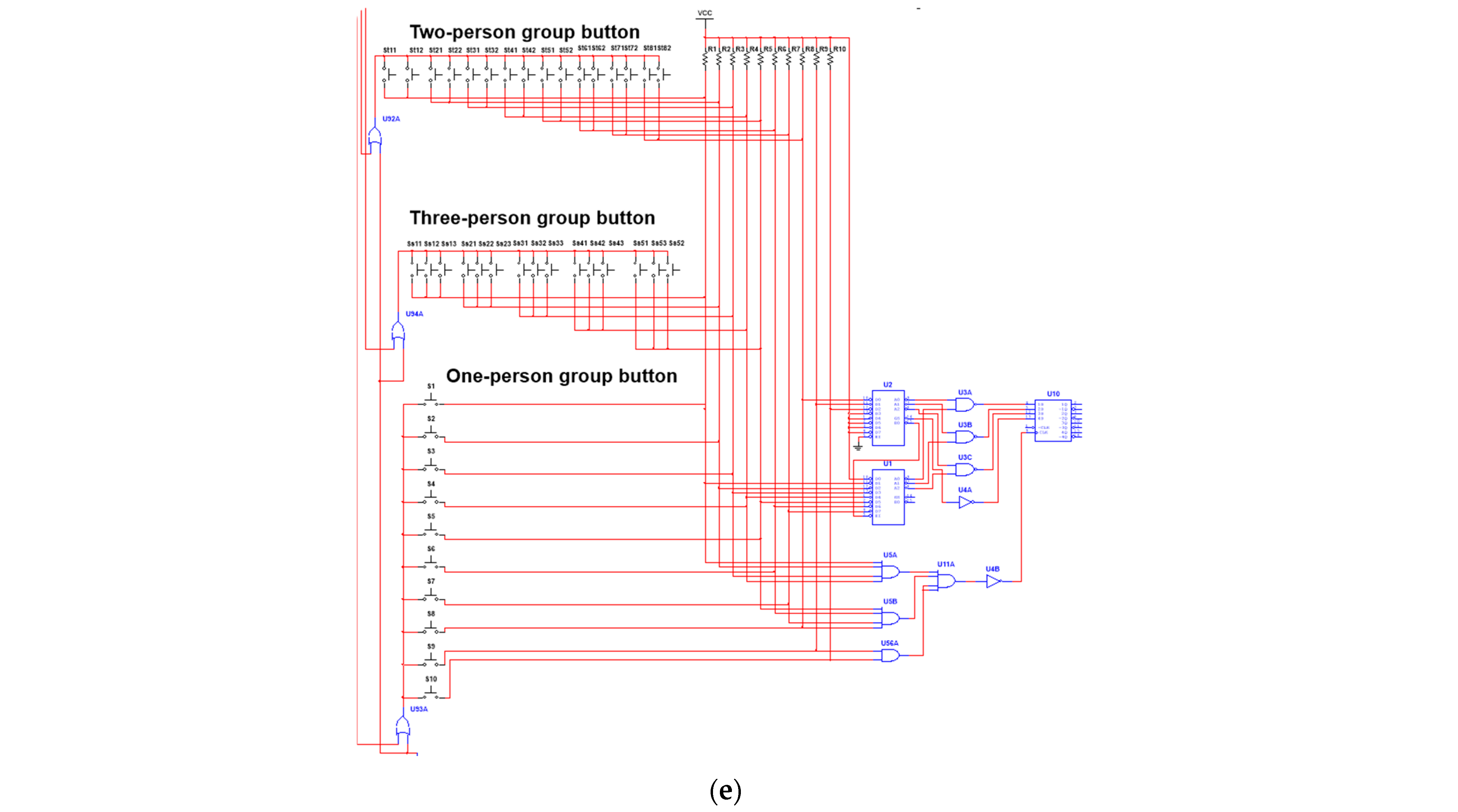
To accommodate diverse scenarios, the team-versus-team buzz-in mode is extended to support two- or three-member teams, as shown in Figure 5e. In conjunction with Section A of the main schematic, when the moderator selects a mode, the associated buzz-in enable is activated, whereas the enable lines for other modes remain disabled. A press by any team member within the configured time window registers a successful team buzz-in. The signal propagates through a flip-flop to the LED indicator, illuminating the member’s channel LED. The latch holds this state until the moderator resets, preventing subsequent presses from other teams.
The buzzer system provides a configurable response window of up to 99 s, adjustable per question requirements. Each response round is initiated by the host (via the main control switch). Timing is configured via two hardware keys (tens-setting and units-setting), which write the digits to their respective counters; the LED display updates in real time. The host main control switch initiates the countdown, and a green indicator shows the active state. During the countdown, the setting is latched and cannot be modified; it can be cleared only after the cycle completes or via manual reset. Push buttons are used in place of Dual Inline Package (DIP) switches to reduce size, enable flexible adjustments, lower the risk of mis-operation, and improve usability.
If the countdown expires with no contestant buzzing in, the round is declared invalid. The countdown shows “00”; a logic path composed of OR/NOT stages drives the buzzer to issue a stop-timing alert; simultaneously, contestant inputs are controlled so that the input channels are locked out, preventing late answers.

4.2.2. Answer Timing

As shown in Figure 6, this module follows principles like the previous one. The buzz-in event generates an input that is combined by a synchronous programmable counter to drive the seven-segment display corresponding to the answer time; the answering window is limited to 60 s. Two synchronous counters are cascaded to extend the bit width; a BCD decoder/driver then feeds the displays for the ones and tens digits of the answering countdown. The counting clock is provided by an oscillator built from a timer; the remaining answer time is displayed on the seven-segment display and held until moderator reset.

4.3. Violation Alarm Module

As shown in Figure 6, a ten-input AND network is formed at the contestants’ button inputs. When a contestant presses prematurely, the corresponding input goes low; after inversion, the signal drives the alarm LED. Because push buttons are used and no latching is involved in the alarm path, the output remains high only briefly before returning low, producing a blinking alarm indication.
An audible indication is also provided: a decade counter is clocked by a 1 Hz pulse from the pulse-generation circuit. When the count reaches the 10th second, the carry-out toggles from low to high and, after inversion, is fed to the buzzer input to stop the tone. Consequently, if a contestant presses before the moderator announces the start, the alarm is triggered: the alarm LED blinks, and the buzzer emits a 9 s tone that stops automatically at 9 s.
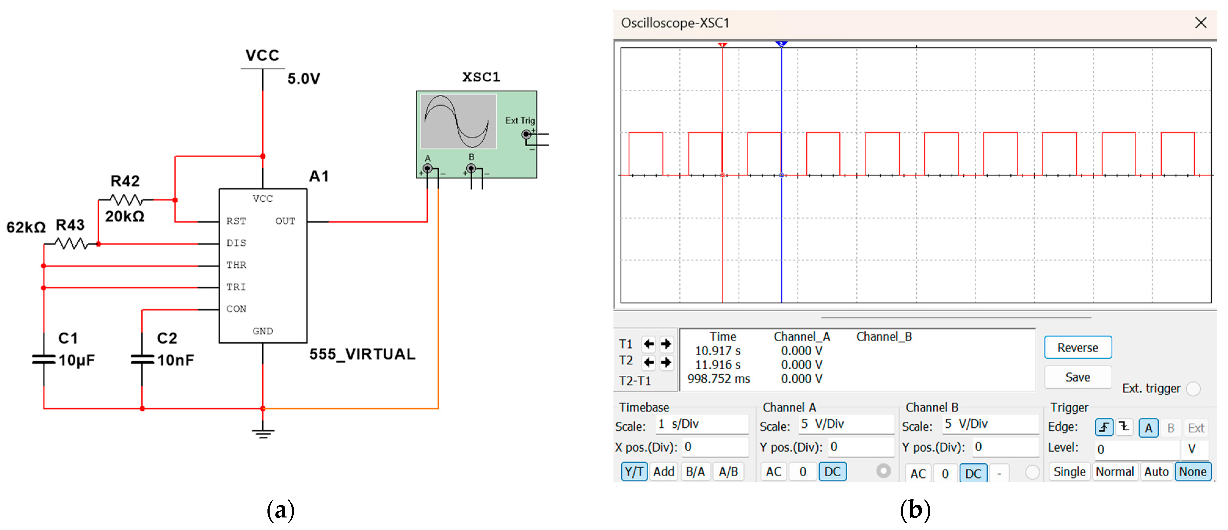
For both the countdown and the 9 s alarm, a 1 Hz pulse generator is required to produce a rectangular wave with a stable amplitude and accurate period (target period, 1 s, i.e., 1 Hz). As shown in Figure 7a, the implementation employs a 555 Timer Astable Oscillator (Texas Instruments, headquartered in Dallas, Texas, USA.) with external resistors and a capacitor. The supply Vcc charges the capacitor through R42 and R43, raising the capacitor voltage. When the capacitor voltage reaches the upper threshold (2/3 Vcc), the output Uo goes low and the internal discharge switch turns on; the capacitor discharges through R43, causing the voltage to fall. When the capacitor voltage drops to the trigger threshold (1/3 Vcc), Uo goes high and the discharge switch turns off. Repeating this process yields a stable oscillation that provides the 1 Hz time base for the system.
In a 555 Timer astable configuration, the charge time TH (from 1/3 Vcc to 2/3 Vcc) and discharge time TL (from 2/3 Vcc to 1/3 Vcc) are
T H = 0.693 R 42 + R 43 C 1 , T L = 0.693 R 43 C 1  
Hence, the period and oscillation frequency are
T = T H + T L = 0.693 R 42 + 2 R 43 C 1 ,   f = 1 T
Substituting into T (cf. Equation (13)) gives 0.998 s, so f is 1.00 Hz.
R 42 = 20   k Ω ,   R 43 = 62   k Ω , C 1 = 10   μ F ,
The astable output is shown in Figure 7b. With an oscilloscope attached to the pulse-generator output, the waveform period is observable; moving the oscilloscope cursors yields a single-cycle duration of 1 s, confirming the practicality of the design.

5. System Integration and Performance Testing

5.1. System-Level Evaluation

5.1.1. Functional Testing Results

The simulation-and-verification workflow for the system’s three-layer robustness chain—pixel level (filtering + Otsu), geometric level (Neighbor-Point Fusion + Perspective Rectification), and codeword level (Reed–Solomon error correction)—is shown in Figure 8a. The figure provides a systematic, end-to-end protocol and stress setup for the Participant Information Registration subsystem: Construct Participant QR Code Repository generates and manages a unique QR Code per contestant; after Symbology Selection, the input source is the on-site Real-World Image Input. To emulate real contest conditions, seven representative perturbations are injected on the input side (green modules): Salt-and-Pepper Noise, Gaussian Noise, Shadowing, Skew, Surface Creasing, Missing Regions, and Smudging, thereby testing robustness under both random noise and structural distortions. The pipeline then enters Image Preprocessing (purple modules): Grayscale Conversion followed by Adaptive Thresholding (Otsu) for stable binarization; three denoising branches—Mean Filtering (imfilter), Median Filtering (medfilt2), and Wiener Filtering (wiener2)—are run in parallel and Assess Result Consistency compares the decoded outputs of the three paths on the same QR target as a pixel-level robustness criterion. In Decoding (blue backbone), two key reinforcements (yellow modules) are included: Neighbor-Point Fusion averages candidate key points within radius r and iteratively shrinks to remove outliers, stabilizing the three Finder-Pattern coordinates; Perspective Rectification estimates the homograph H from the three corners, removing tilt-induced trapezoidal distortion. The geometrically rectified bitstream is then passed to Reed–Solomon Error Correction for syndrome computation, error localization, and correction, maintaining decodability even under occlusion or damage. Recognition Results output the contestant identity and related metadata and transition seamlessly to Awaiting Answer, linking to the hardware chain of concurrent arbitration, configurable timing, and violation alarm.
The above reproducible criteria—agreement across multiple preprocessing/decoding paths and successful localization → rectification → RS-based recovery under diverse perturbations—are consistent with the portable implementation (MATLAB/ZXing), recognition-accuracy goals, and system-level integration objectives, thereby providing clear experimental evidence for scalable deployment. As an illustrative example, Figure 8b shows the 1D barcode, QR Code, and recognition output for contestant Zhang San from the Shu Guang team (ID 01).
To further assess the robustness of the registration process, identification success-rate tests were conducted under seven representative disturbances. Gaussian and salt-and-pepper noise were synthesized with MATLAB imnoise; the remaining disturbances were applied manually in 60 groups at graded intensities. Each group used a random subset of source QR Codes to reduce selection bias. In addition to recognition accuracy (Acc), the metrics included a consistency ratio (Consis—the fraction of correct cases whose three-path denoising decodes yielded identical text) and per-sample processing time (Time).
Table 1 reports results across the evaluated perturbations. After neighboring-point fusion and perspective correction, skew/perspective distortion retains high Accuracy (93.3%) and Consistency (86.0%). Local low contrast from shadows or smudges reduces Consistency, whereas Accuracy remains at 83–85% with TRY_HARDER, with moderate ROI relaxation and mild denoising. With missing-pixel occlusion, Acc is 78.3%, mainly because occlusion induces codeword-field loss beyond the correction capability of RS codes. The computation time varies little across perturbations, indicating a limited and controllable impact on system latency. Overall, the system achieves a mean Acc of 86.7%, mean Consis of 73.6%, and mean per-sample computation time of 14 ms across perturbations.
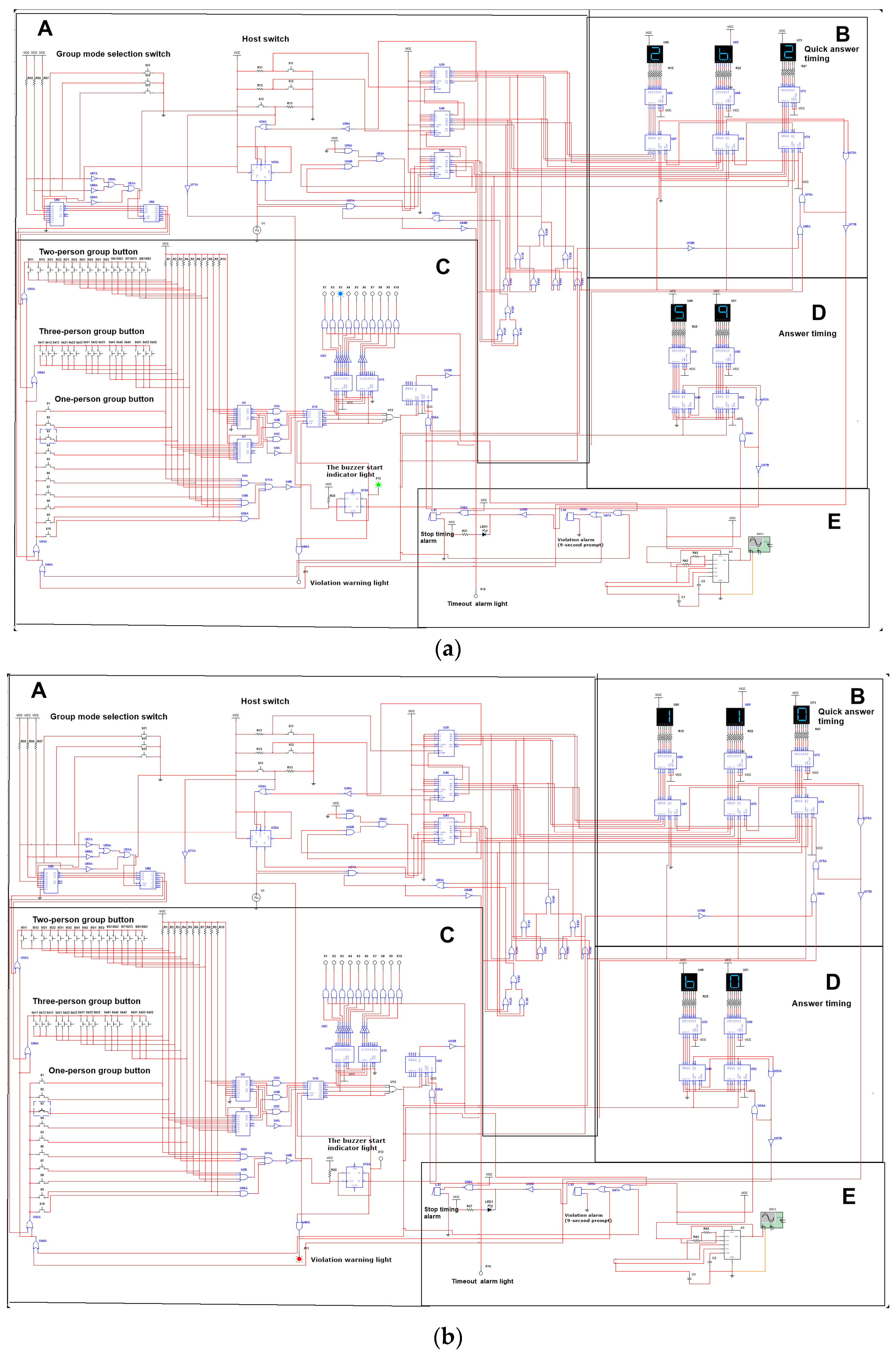
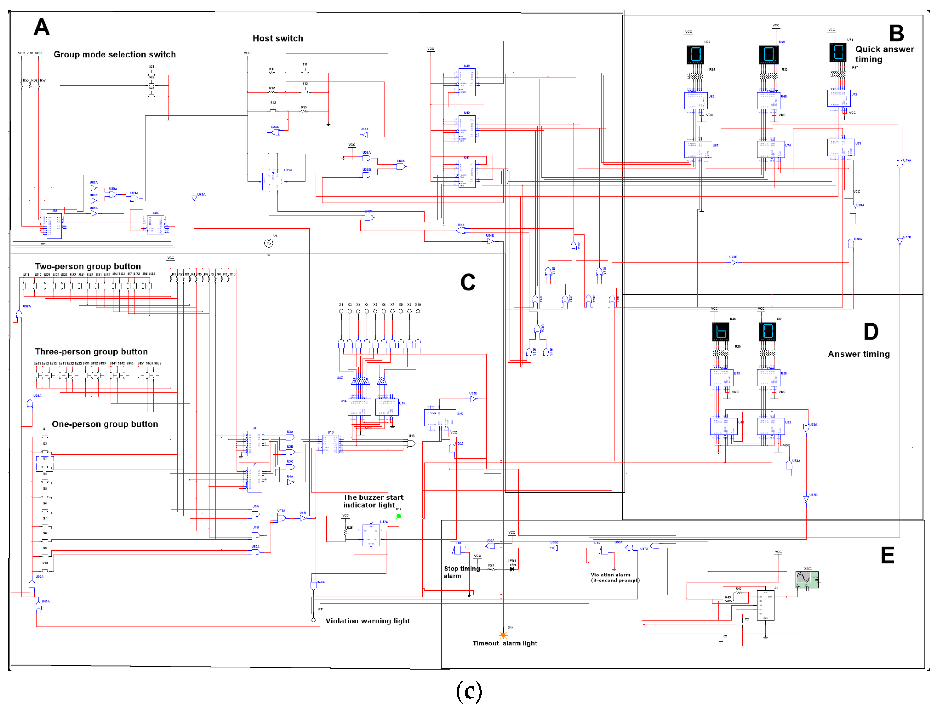
Answering the stage simulation workflow is shown in Figure 8c. After the moderator sets the countdown and presses the control switch, the green indicator lights to denote the start of the buzz-in module; contestant #6 then presses first at 31 s, the corresponding blue indicator turns on, other buttons are immediately disabled, and the answer timer starts from 60 s. Figure 9a shows the answering countdown at 58 s. The violation-alarm simulation in Figure 9b indicates a red light and an active buzzer upon premature buzz-in. The timeout-no-buzz simulation in Figure 9c shows that when the moderator’s buzz-in window ends with no contestant response, the timeout buzzer activates and the timeout indicator lights; pressing the reset switch returns the system to its initial state.
Participant scalability is realized through two components: single-user expansion and team expansion.
(1) Single-user expansion. The prototype employs two 74LS148 priority encoders for single-user buzz-in detection, providing up to 16 independent buttons. For larger channel counts (e.g., 24 or 32), additional 74LS148 devices can be cascaded per the datasheet. To display the first-to-press channel, the encoded output is latched (e.g., 74LS175) before being decoded by the 74LS138. When more than eight channels are required, indicator lines are expanded by cascading 74LS138 decoders via their enable pins. Button inputs follow an active-low convention, and jitter/retriggers are suppressed by the existing shaping and first-trigger latching.
(2) Team expansion. The system supports team-based modes for pairs and trios. Buttons from the same team are combined through diode-OR wiring (wired-OR for active-low) into a single active-low input of the 74LS148; this prevents cross-channel back feed and interference. Unselected team lines are held high. Mode switching uses the 74LS145’s active-low selection outputs together with the enable/gating pins of the 74LS148: only the selected team’s network is enabled, and other modes are gated off. Thus, in two- or three-person modes, pressing any button within the team asserts that channel. Subsequent processing follows the “first-trigger latch → display indication” sequence, while unselected paths remain disabled.

5.1.2. Performance Comparison

Table 2 compares the power, cost, and deployment complexity across the technical solutions. Comparisons assume identical peripherals and loads: 5 V supply; a two-digit seven-segment display (10 mA per segment, 1/2 multiplexing); 10 indicator LEDs (two lit on average, 5–10 mA each); and a buzzer with a ≈10% duty cycle. System-level power equals board power plus peripheral-driver power. With identical peripherals, system-level power for the discrete 74-series design is dominated by LED/seven-segment drivers and falls in the ≈1.5–3.0 W range. Comparable MCU/ESP32/STM32 designs with the same peripherals show similar or slightly lower system-level power. The small-batch prototype BOM (74xx/4000 + seven-segment/LED/buzzer + PCB/connectors) is ≈$25–$40; MCU/ESP32 solutions with equivalent peripherals are comparable; FPGA dev-board solutions are substantially higher. Deployment complexity is graded as follows: this system—no firmware, plug-and-play, but extensive wiring (Moderate); Arduino/ESP32—mature Integrated Development Environment (IDEs)/libraries (Moderate; basic firmware and wiring required); STM32—substantial peripheral/middleware configuration (Difficult); FPGA—HDL development, timing closure, and power planning (Challenging). Overall, the system compares favorably in power, cost, and deployment complexity.
The engineering focus is determinism, fairness, and offline usability rather than aggressive reductions in power or the BOM cost. Priority encoding and first-trigger latching are realized at the gate level; worst-case delay is set by logic-propagation and the time base and is immune to firmware scheduling, interruptions, and load variation. The 0–99 s timing is loaded via the 74LS192 preset (synchronous-load) pins. Answer-timing presets are fixed, improving usability and reducing the error risk. Participant expansion is realized by cascading 74LS148 priority encoders and 74LS138 decoders, keeping timing/priority effects transparent. This facilitates debugging and auditing in educational and examination settings. These conclusions apply only to prototype-level implementations under the stated assumptions. Commercial products are excluded because the integration level and drive strategy vary widely, yielding non-comparable power and cost.

5.2. Usability and Ethical Considerations

This system operates offline and provides a compact interface comprising a main control switch, indicator lights, and a digital display. It supports single-user and two- or three-person team modes, with configurable 0–99 s timing and one-touch reset. A first-trigger latch and audible/visual alerts for violations and time-outs make decisions auditable and immediately perceivable. These features facilitate on-site orchestration for classroom and school-wide events.
Data processing follows data-minimization and purpose-limitation principles: QR Codes encode only an internal identifier (optionally, a group identifier) and no facial or other biometric data; camera frames are processed in memory and are not stored by default; persistent records comprise structured event-level metadata (timestamps, channel/group selection, buzz-in/response durations, violation/time-out events, internal identifier) for classroom statistics and post-event analysis. By default, logs are stored locally on the competition terminal; data are not uploaded to third-party services. Exports are local files (e.g., CSV) to enable integration with campus teaching platforms.
For educational deployments, randomized internal identifiers are recommended, with local mapping tables maintained by course administrators. Retention should comply with course or school privacy policies; detailed data should be purged periodically, retaining only the aggregated statistics necessary for pedagogical evaluation.

5.3. Portability and Runtime Performance

The system’s information-extraction and decoding pipeline comprises platform-agnostic pixel/geometric operations and a standard decoding library, supporting portability. Grayscale conversion and lightweight denoising used in the prototype can be realized with equivalent operators on mobile/embedded devices. Perspective correction uses a single-view planar homography estimated from the three Finder-Pattern references, and the decoding stage reuses the ZXing implementation consistent with the prototype. To balance latency and compute on mobile/embedded platforms without compromising correctness, the system adopts ROI-first decoding with fallback to the full image, short-edge normalization, and on-demand retries (HybridBinarizer → GlobalHistogramBinarizer; multi-scale/rotation triggered only on failure). POSSIBLE_FORMATS = {QR_CODE} constrains the search space; TRY_HARDER is enabled only in low-contrast scenarios; PURE_BARCODE is attempted only for near-pure ROIs (tight crops with a clean quiet zone). Based on desktop phase-wise measurements (Table 1), the mean per-sample time for information extraction is ≈14 ms, with limited variation across perturbations. These measurements serve as scale references; platform-specific real-time performance and power consumption on target mobile/embedded devices will be reported in subsequent prototype tests.

6. Conclusions

An integrated information-recognition and multi-participant quiz system tailored to educational competitions has been proposed and validated, encompassing participant registration, team formation, and buzz-in adjudication. For registration, a portable barcode pipeline (MATLAB/ZXing) integrates 1D/2D code generation and recognition, coupled with grayscale conversion → Adaptive Thresholding (Otsu) → Neighbor-Point Fusion → Perspective Rectification → Reed–Solomon error correction, which markedly increases throughput and reduces manual-entry errors. The Multisim-based compulsory-round circuitry, together with seven-segment displays, supports up to nine questions with independent scoring for accurate recording and cross-checking. To enrich the buzz-in experience, the team-versus-team mode has been extended to support two- or three-person teams. For the buzz-in module, a priority-encoding with first-hit latching digital-logic scheme enables deterministic arbitration across 10 concurrent inputs; a 0–99 s configurable buzz-in window and a 60 s answering countdown are provided, along with violation alarms for early presses, overcoming limitations of fixed timing and channel-bound designs.
Functional and stability simulations indicate the stable presentation of identity/group/time states, reliable first-buzz latching with effective masking of subsequent channels, and suitability for rapid deployment in small- to mid-scale contests, improving the registration accuracy and adjudication/recording efficiency. A 1 Hz time base derived from a 555 Timer astable oscillator ensures timing accuracy and repeatability. Relative to MCU channel-based architectures, the proposed digital-logic design relaxes hardware-channel constraints, delivers predictable arbitration latency, and offers flexible timing configuration, while preserving cascadability and cost controllability. The integrated workflow—recognition → identity binding → concurrent arbitration → configurable timing → process logging—facilitates replicable deployment and end-to-end traceability across the contest lifecycle. The Participant Information Registration subsystem achieved a mean accuracy of 86.7% and a mean per-sample computation time of 14 ms.
The primary limitations stem from the verification approach, which is dominated by simulation and functional testing. The prototype verifies logic correctness and latch/register robustness under ten concurrent channels. Further participant scaling is constrained by the propagation delay, fan-out, and routing complexity introduced by cascading 74LS148/138 devices. Timing accuracy is limited by the 555-timer RC tolerances and temperature drift. Timing distributions for input-side key bounce and asynchronous arrivals have not yet been measured on physical hardware. QR-Code recognition remains borderline under large-area occlusions that exceed RS correction capability or under extreme shadowing/perspective. Future work will evaluate physical prototypes for high-concurrency cascading and system stability. Planned measurements include arbitration-delay and jitter distributions and timing-error statistics under uniform conditions at full load. Mitigations will include Schmitt-trigger shaping, hardware de-jittering, synchronous clocking, and an XO/TCXO-derived time base via frequency division. The end-to-end recognition accuracy and processing time under field perturbations will be reported; cross-platform porting (e.g., Python/OpenCV) and mobile-acquisition integration will be advanced. Ultimately, comparative data on scalability and stability will be provided against representative systems, and circuit-/parameter-level optimizations will be performed based on prototype results.
Future cross-platform deployment roadmap. Implement grayscale conversion, lightweight denoising, binarization, Finder-pattern localization, and homography-based perspective correction with Python/OpenCV; use ZXing-cpp for decoding to preserve workflow equivalence. Optimize latency on ARM-based single-board computers (SBCs) and mobile devices using ROI-first decoding, short-edge normalization, and on-demand fallbacks (HybridBinarizer → GlobalHistogramBinarizer; multi-scale/rotation triggered only on failure). Measure end-to-end latency and power consumption and perform bottleneck analysis (per-step timings for image reading, binarization, and decoding); then, conduct parameter restriction/tuning and lightweight optimizations based on the findings. After ethical approval, conduct small-scale classroom pilots and present side-by-side comparisons against an MCU channel–based buzzer system.

Author Contributions

Conceptualization, J.L. and W.B.; methodology, W.B.; software, Y.D.; validation, J.L., W.B., and Y.D.; formal analysis, W.B.; investigation, J.L.; resources, T.Z. and X.Y.; data curation, T.Z. and X.Y.; writing—original draft preparation, J.L. and W.B.; writing—review and editing, Y.D. and B.K.; visualization, J.L.; supervision, B.K.; project administration, T.Z. and X.Y.; funding acquisition, B.K. All authors have read and agreed to the published version of the manuscript.

Funding

This research received no external funding.

Institutional Review Board Statement

Ethical review and approval were waived for this study in accordance with Article 32 of the Administrative Measures for Ethical Review of Life Science and Medical Research Involving Humans (promulgated on 18 February 2023 by the National Health Commission, Ministry of Education, Ministry of Science and Technology, and National Administration of Traditional Chinese Medicine of China). The work involves no human participants, no collection or processing of personal/identifiable data, and no biological specimens; all evaluations were performed via virtual simulations to verify system functionality and performance. As the research does not cause harm to humans and does not involve sensitive personal information or commercial interests, it meets the criteria for exemption from ethical review under Article 32 (official text available at: https://www.nhc.gov.cn/qjjys/c100016/202302/6b6e447b3edc4338856c9a652a85f44b.shtml, accessed on 23 January 2025). Any future studies that include human participants will obtain prior approval from the appropriate institutional ethics committee.

Informed Consent Statement

Not applicable.

Data Availability Statement

The original contributions presented in this study are included in the article. Further inquiries can be directed to the corresponding authors.

Conflicts of Interest

The authors declare no conflict of interest.

Appendix A

Appendix A.1

For Mean Filtering,
I f ( x , y ) = 1 m n i = m / 2 m / 2 j = n / 2 n / 2 I ( x + i , y + i )
where I is the original grayscale image matrix; x and y are the coordinates of the pixel being processed; m and n are the filter-kernel dimensions (rows × columns); i and j are the relative offsets within the kernel. For Median Filtering,
I f ( x , y ) = m e d i a n ( i , j ) W I ( x + i , y + j )
where W is the window (kernel) region, i and j are the relative offsets within W, and “median” denotes the median operator (the middle value of all pixels in the window). For Gaussian Filtering, the Gaussian kernel is and the discrete convolution is
G ( x , y ) = 1 2 π σ 2 e x 2 + y 2 2 σ 2
and the discrete convolution is
I f i l t e r e d ( x , y ) = i = k k j = k k I ( x + i , y + j ) G ( i , j )
Here, σ is the standard deviation of the Gaussian; k is the kernel half-width; indices (i,j) are measured relative to the kernel origin (centered at (0,0)).

Appendix A.2

The homograph matrix H is
H = a b c d e f g h 1
where a and e are the scaling factors in the x- and y-directions, c and f are translations in x and y, b and d are the inter-axis shear terms (used to correct parallelogram-type deformations), and g and h are perspective parameters (used to remove trapezoidal distortion caused by camera tilt).
The following mapping holds:
x y 1 = H x y 1
with (x, y) the unrectified input coordinates and (x′, y′) the rectified output.
After homogeneous normalization,
x = a x + b y + c g x + h y + 1 , y = d x + e y + f g x + h y + 1
The matrix H is estimated by least squares to map source points (xi, yi) to target points (xi′, yi′).
x i ( g x i + h y i + 1 ) = a x i + b y i + c y i ( g x i + h y i + 1 ) = d x i + e y i + f
Stacking the correspondence equations yields a linear system of the form
x 1 y 1 1 0 0 0 x 1 x 1 x 1 y 1 0 0 0 x 1 y 1 1 y 1 x 1 y 1 y 1 x 4 y 4 1 0 0 0 x 4 x 4 x 4 y 4 0 0 0 x 4 y 4 1 y 4 x 4 y 4 y 4 a b c d e f g h = x 1 y 1 x 4 y 4
By solving the parameter vector, the matrix H can be reconstructed.

Appendix A.3

Let the received codeword be r (possibly corrupted).
(1) Syndrome computation.
s j = r ( α j ) = i = 0 n 1 r i ( α j ) i , j = 0 ,   1 ,   ,   2 t 1
where α is a primitive element. If all syndromes are zero, the block is error-free; otherwise, errors are present.
(2) Error-locator polynomial. Use the Berlekamp–Massey algorithm to iteratively obtain the error-locator polynomial,
Λ x = 1 + Λ 1 x + Λ 2 x 2 + + Λ t x t , s j + Λ 1 s j 1 + + Λ t s j t = 0 , j t
(3) Error location. Find the roots of Λ(x) via a Chien search. If Λ(αi) is 0, then, the symbol at position i is in error.
(4) Error magnitude. Let the error position be ik and the error magnitude be eik. Using Forney’s formula,
e i k = Ω α i k Λ α i k
where Ω x is the error value polynomial and Λ x is the derivative of Λ x .
(5) Error correction.
c i = r i e i

References

  1. Corsini, F.; Gusmerotti, N.M.; Testa, F.; Frey, M. Exploring the drivers of the intention to scan QR codes for environmentally related information when purchasing clothes. J. Glob. Fash. Mark. 2025, 16, 18–31. [Google Scholar] [CrossRef]
  2. Alam, S.S.; Ahmed, S.; Kokash, H.A.; Mahmud, M.S.; Sharnali, S.Z. Utility and hedonic perception—Customers’ intention towards using of QR codes in mobile payment of Generation Y and Generation Z. Electron. Commer. Res. Appl. 2024, 65, 101389. [Google Scholar] [CrossRef]
  3. Pathak, S.K.; Jain, R. Use of QR Code Technology for Providing Library and Information Services in Academic Libraries: A Case Study. Pearl J. Libr. Inf. Sci. 2018, 12, 43. [Google Scholar] [CrossRef]
  4. AlNajdi, S.M. The effectiveness of using augmented reality (AR) to enhance student performance: Using quick response (QR) codes in student textbooks in the Saudi education system. Educ. Technol. Res. Dev. 2022, 70, 1105–1124. [Google Scholar] [CrossRef]
  5. Yan, L.Y.; Tan, G.W.H.; Loh, X.M.; Hew, J.J.; Ooi, K.B. QR code and mobile payment: The disruptive forces in retail. J. Retail. Consum. Serv. 2021, 58, 102300. [Google Scholar] [CrossRef]
  6. Dey, S.; Saha, S.; Singh, A.K.; McDonald-Maier, K. FoodSQRBlock: Digitizing food production and the supply chain with blockchain and QR code in the cloud. Sustainability 2021, 13, 3486. [Google Scholar] [CrossRef]
  7. Jiang, H.; Vialle, W.; Woodcock, S. Redesigning Check-In/Check-Out to Improve On-Task Behavior in a Chinese Classroom. J. Behav. Educ. 2023, 34, 371–398. [Google Scholar] [CrossRef]
  8. Madorin, S.; Laleff, E.; Lankshear, S. Optimizing Student Self-Efficacy and Success on the National Registration Examination. J. Nurs. Educ. 2023, 62, 535–536. [Google Scholar] [CrossRef]
  9. Zhang, Y.; Yang, F.; Yang, H.; Han, S. Does checking-in help? Understanding L2 learners’ autonomous check-in behavior in an English-language MOOC through learning analytics. ReCALL 2024, 36, 343–358. [Google Scholar] [CrossRef]
  10. Bockstedt, J.; Druehl, C.; Mishra, A. Incentives and stars: Competition in innovation contests with participant and submission visibility. Prod. Oper. Manag. 2022, 31, 1372–1393. [Google Scholar] [CrossRef]
  11. Tsai, K.Y.; Wei, Y.L.; Chi, P.S. Lightweight privacy-protection RFID protocol for IoT environment. Internet Things 2025, 30, 101490. [Google Scholar] [CrossRef]
  12. Tu, Y.J.; Zhou, W.; Piramuthu, S. Critical risk considerations in auto-ID security: Barcode vs. RFID. Decis. Support Syst. 2021, 142, 113471. [Google Scholar] [CrossRef]
  13. Ferreira, M.C.; Dias, T.G.; e Cunha, J.F. ANDA: An innovative micro-location mobile ticketing solution based on NFC and BLE technologies. IEEE Trans. Intell. Transp. Syst. 2021, 23, 6316–6325. [Google Scholar] [CrossRef]
  14. JosephNg, P.S.; BrandonChan, P.S.; Phan, K.Y. Implementation of Smart NFC Door Access System for Hotel Room. Appl. Syst. Innov. 2023, 6, 67. [Google Scholar] [CrossRef]
  15. Huberty, J.; Green, J.; Puzia, M.; Stecher, C. Evaluation of mood check-in feature for participation in meditation mobile app users: Retrospective longitudinal analysis. JMIR Mhealth Uhealth 2021, 9, e27106. [Google Scholar] [CrossRef] [PubMed]
  16. Xu, F.Z.; Zhang, Y.; Zhang, T.; Wang, J. Facial recognition check-in services at hotels. J. Hosp. Mark. Manag. 2021, 30, 373–393. [Google Scholar] [CrossRef]
  17. Liu, J.; Chen, C. Optimal Design of Sports Event Timer Structure Based on Ferroelectric Memory. J. Nanomater. 2022, 1, 6712693. [Google Scholar] [CrossRef]
  18. Read, R.L.; Kincheloe, L.; Erickson, F.L. General purpose alarm device: A programmable annunciator. HardwareX 2024, 20, e00590. [Google Scholar] [CrossRef]
  19. Huang, L.; Sun, Y. User Repairable and Customizable Buzzer System using Machine Learning and IoT System. In Proceedings of the Computer Science & Information Technology (CS & IT) Conference, Chennai, India, 20–21 August 2022. [Google Scholar]
  20. Khan, M.M.; Tasneem, N.; Marzan, Y. ‘Fastest Finger First—Educational Quiz Buzzer’ Using Arduino and Seven-Segment Display for Easier Detection of Participants. In Proceedings of the 2021 IEEE 11th Annual Computing and Communication Workshop and Conference (CCWC), Las Vegas, NV, USA, 27–30 January 2021; pp. 1093–1098. [Google Scholar]
  21. Wurtele, S.K.; Drabman, R.S. “Beat the buzzer” for classroom dawdling: A one-year trial. Behav. Ther. 1984, 15, 403–409. [Google Scholar] [CrossRef]
  22. Nkeleme, V.O.; Tahir, A.A.; Mohammed, Y. Design and Implementation of Classroom Crowd Monitoring System. Afr. Sch. J. Afr. Innov. Adv. Stud. (JAIAS-2) 2022, 2, 165–178. [Google Scholar]
  23. Mashat, A. A QR code-enabled framework for fast biomedical image processing in medical diagnosis using deep learning. BMC Med. Imaging 2024, 24, 198. [Google Scholar] [CrossRef]
  24. Huo, L.; Zhu, J.; Singh, P.K.; Pavlovich, P.A. Research on QR image code recognition system based on artificial intelligence algorithm. J. Intell. Syst. 2021, 30, 855–867. [Google Scholar] [CrossRef]
  25. Kim, J.I.; Gang, H.S.; Pyun, J.Y.; Kwon, G.R. Implementation of QR code recognition technology using smartphone camera for indoor positioning. Energies 2021, 14, 2759. [Google Scholar] [CrossRef]
  26. Xu, J.; Li, Z.; Zhang, K.; Yang, J.; Gao, N.; Zhang, Z.; Meng, Z. The principle, methods and recent progress in RFID positioning techniques: A review. IEEE J. Radio Freq. Identif. 2023, 7, 50–63. [Google Scholar] [CrossRef]
  27. Zhang, B.; Li, S.; Qiu, J.; You, G.; Qu, L. Application and research on improved adaptive Monte Carlo localization algorithm for automatic guided vehicle fusion with QR code navigation. Appl. Sci. 2023, 13, 11913. [Google Scholar] [CrossRef]
  28. Sun, D. Mathematics of QR Codes: History, Theory, and Implementation. Intell. Planet J. Math. Its Appl. 2025, 2, 1–12. [Google Scholar]
  29. Ohigashi, T.; Kawaguchi, S.; Kobayashi, K.; Kimura, H.; Suzuki, T.; Okabe, D.; Ishibashi, T.; Yamamoto, H.; Inui, M.; Miyamoto, R.; et al. Detecting fake QR codes using information from error-correction. J. Inf. Process. 2021, 29, 548–558. [Google Scholar] [CrossRef]
  30. Estevez, R.; Rankin, S.; Silva, R.; Indratmo, I. A model for web-based course registration systems. Int. J. Web Inf. Syst. 2014, 10, 51–64. [Google Scholar] [CrossRef]
  31. Redolar Soldado, S. Development and Evaluation of a System for Detecting Barcodes and QR Codes Using YOLO11: A Comparative Study of Accuracy and Efficiency. Bachelor’s Thesis, Universitat Politècnica de València, Valencia, Spain, 2025. [Google Scholar]
  32. Barzazzi, D. A Quantitative Evaluation of the QR Code Detection and Decoding Performance in the Zxing Library. Master’s Thesis, Università Ca’ Foscari Venezia, Venice, Italy, 2023. [Google Scholar]
  33. Powell, C.; Shaw, J. Performant barcode decoding for herbarium specimen images using vector-assisted region proposals (VARP). Appl. Plant Sci. 2021, 9. [Google Scholar] [CrossRef] [PubMed]
  34. Sellers, K.K.; Gilron, R.E.; Anso, J.; Louie, K.H.; Shirvalkar, P.R.; Chang, E.F.; Little, S.J.; Starr, P.A. Analysis-rcs-data: Open-source toolbox for the ingestion, time-alignment, and visualization of sense and stimulation data from the Medtronic Summit RC+S system. Front. Hum. Neurosci. 2021, 15, 714256. [Google Scholar] [CrossRef]
  35. Vatsa, A.; Hati, A.S.; Kumar, P.; Margala, M.; Chakrabarti, P. Residual LSTM-based short duration forecasting of polarization current for effective assessment of transformers insulation. Sci. Rep. 2024, 14, 1369. [Google Scholar] [CrossRef]
  36. Prud’homme, A.; Nabki, F. Cost-effective photoacoustic imaging using high-power light-emitting diodes driven by an avalanche oscillator. Sensors 2025, 25, 1643. [Google Scholar] [CrossRef]
  37. Yang, S.; Li, D.; Feng, J.; Gong, B.; Song, Q.; Wang, Y.; Yang, Z.; Chen, Y.; Chen, Q.; Huang, W. Secondary order RC sensor neuron circuit for direct input encoding in spiking neural network. Adv. Electron. Mater. 2024, 10, 2400075. [Google Scholar] [CrossRef]
  38. Chan, E.K.F.; Othman, M.A.; Razak, M.A. IoT based smart classroom system. J. Telecommun. Electron. Comput. Eng. 2017, 9, 95–101. [Google Scholar]
  39. Burunkaya, M.; Duraklar, K. Design and implementation of an IoT-based smart classroom incubator. Appl. Sci. 2022, 12, 2233. [Google Scholar] [CrossRef]
  40. Tribak, H.; Gaou, M.; Gaou, S.; Zaz, Y. QR code recognition based on HOG and multiclass SVM classifier. Multimed. Tools Appl. 2024, 83, 49993–50022. [Google Scholar] [CrossRef]
  41. Yang, S.Y.; Jan, H.C.; Chen, C.Y.; Wang, M.S. CNN-Based QR Code Reading of Package for Unmanned Aerial Vehicle. Sensors 2023, 23, 4707. [Google Scholar] [CrossRef] [PubMed]
  42. Kim, I.P.; Kräuter, A.R. VDR decomposition of Chebyshev–Vandermonde matrices with the Arnoldi Process. Linear Multilinear Algebra 2024, 72, 2810–2822. [Google Scholar] [CrossRef]
  43. Wei, L. Design of Smart Pill Box Using Multisim Simulation. In Proceedings of the Institution of Engineering and Technology (IET) Conference Proceedings CP895, Stevenage, UK, 24–25 June 2024; pp. 418–425. [Google Scholar]
  44. Liu, Z. Systematic Analysis of Sequential Circuits in Digital Clock and Its Display Mode Comparison. Appl. Comput. Eng. 2025, 129, 51–57. [Google Scholar] [CrossRef]
  45. Samoylenko, V.; Fedorenko, V.; Kucherov, N. Modeling of the Adjustable DC Voltage Source for Industrial Greenhouse Lighting Systems. In Proceedings of the International Conference on Actual Problems of Applied Mathematics and Computer Science, Cham, Switzerland, 3–7 October 2022; pp. 167–178. [Google Scholar]
  46. Teoh, M.K.; Teo, K.T.; Yoong, H.P. Numerical computation-based position estimation for QR code object marker: Mathematical model and simulation. Computation 2022, 10, 147. [Google Scholar] [CrossRef]
  47. Wang, W.; Huai, C.; Meng, L. Research on the detection and recognition system of target vehicles based on fusion algorithm. Math. Syst. Sci. 2024, 2, 2760. [Google Scholar] [CrossRef]
  48. Kadhim, S.A.; Yas, R.M.; Abdual Rahman, S.A. Advancing IoT Device Security in Smart Cities: Through Innovative Key Generation and Distribution With D_F, GF, and Multi-Order Recursive Sequences. J. Cybersecur. Inf. Manag. 2024, 13, 84–95. [Google Scholar]
  49. Abas, A.; Yusof, Y.; Ahmad, F.K. Expanding the data capacity of QR codes using multiple compression algorithms and base64 encode/decode. J. Telecommun. Electron. Comput. Eng. (JTEC) 2017, 9, 41–47. [Google Scholar]
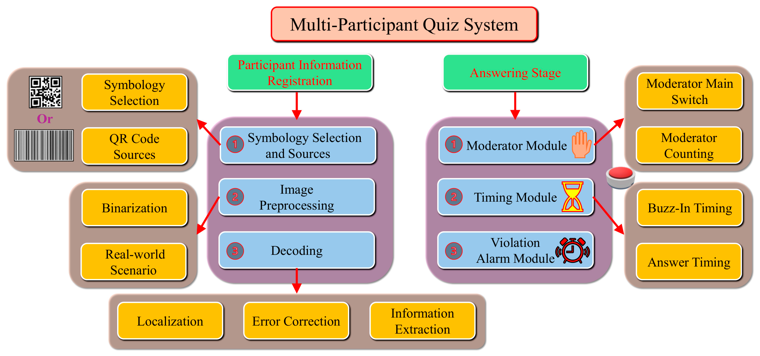
Figure 1. Overall block diagram of the competition system.
Asi 08 00158 g001
Figure 2. Finder-Pattern ratio. A—The size of the innermost black square (the central module of the finder pattern). B—The size including the innermost black, white, and middle black regions (inner three layers). C—The total size of the entire finder pattern, including all black and white regions (five layers in total).
Asi 08 00158 g002
Figure 3. File encapsulation workflow for decoding.
Asi 08 00158 g003
Figure 4. Question-and-answer session procedure: (a) answering stage block diagram; (b) moderator switch module.
Asi 08 00158 g004
Figure 5. Moderator counting circuit and buzz-in timing schemes: (a) moderator counting circuit; (b) buzz-in timing scheme one (The red light indicates that this participant pressed the button first.); (c) buzz-in timing scheme two; (d) buzz-in timing scheme three (The green light indicates that someone has completed the buzzer response, while the blue light identifies the responder.); (e) team-versus-team mode.
Asi 08 00158 g005aAsi 08 00158 g005b
Figure 6. Flowchart of the buzz-in timing (yellow background), answer timing (green background), and violation alarm (pink background) modules. Green boxes indicate human–machine operation nodes (mode selection, time setting, reset); blue boxes represent logic processing or display; and red diamonds denote decision nodes (Yes/No branches).
Asi 08 00158 g006
Figure 7. One-hertz pulse generation principle and simulation: (a) astable oscillator; (b) 1 Hz pulse generation. The red lines represent the power and signal connections between VCC, resistors, capacitors, and the 555 timer pins, while the orange line represents the output signal line from the 555 timer’s OUT pin to the oscilloscope input.
Asi 08 00158 g007
Figure 8. Participant information registration simulation: (a) registration simulation workflow; (b) representative simulation recognition results; (c) answering stage simulation workflow. This QR code is for testing purposes only and does not contain any private information.
Asi 08 00158 g008
Figure 9. Functional simulation of key modules: (a) buzz-in module; (b) premature buzz-in alarm; (c) timeout—no buzz-in. The green light is the buzzer start indicator light, the yellow light is the timeout alarm light, and the red light is the violation warning light. Part A is the Moderator Main Switch, parts B and C are the Buzz-In Timing Module, part D is the Answer Timing Module, and part E is the Violation Alarm Module.
Asi 08 00158 g009aAsi 08 00158 g009b
Table 1. Test results under different perturbations.
PerturbationsAcc (%)Consis (%)Time (ms)
Salt-and-Pepper Noise90.072.214
Gaussian Noise90.077.814
Shadowing83.368.014
Skew93.386.012
Surface Creasing86.774.014
Missing Regions78.361.715
Smudging85.072.514
Average86.773.614
Table 2. Performance comparison of different technical schemes.
Technical SchemesSystem-Level Power Consumption (W)Cost ($)Deployment Complexity
FPGA5–1080–200Challenging
STM320.7–1.530–50Difficult
Arduino Mega 25600.7–1.223–40Moderate
ESP32 0.6–1.016–30Moderate
This system1.5–3.025–40Moderate
Disclaimer/Publisher’s Note: The statements, opinions and data contained in all publications are solely those of the individual author(s) and contributor(s) and not of MDPI and/or the editor(s). MDPI and/or the editor(s) disclaim responsibility for any injury to people or property resulting from any ideas, methods, instructions or products referred to in the content.