1. Introduction
Nanofluids have excellent thermal conductivity [
1,
2,
3,
4,
5,
6,
7,
8,
9,
10,
11] and have been applied as the working fluids in traditional heat pipe applications to enhance thermal performance. “In the presence of an external magnetic field, the thermal conductivity of magnetite nanofluids increases with the increase in the volumetric concentration of magnetic particles, which is associated with the increase in the magnetic field strength” [
12,
13,
14,
15,
16,
17,
18,
19,
20,
21,
22,
23,
24].
Currently, the efficiency of commercial solar PV solar panels is up to 15%, and most incoming solar radiation energy is either absorbed or reflected, and significant excess heat is dissipated and wasted. “To improve the efficiency of solar PVs, the novel concept of a photovoltaic–thermal solar panel hybrid system using nanofluids has been developed [
25,
26,
27,
28,
29,
30,
31]. Regarding the PV–thermal solar hybrid system”, references [
12,
13,
14,
15,
16,
17,
18,
19,
20,
21,
22,
23,
24,
25,
26,
27,
28,
29,
30,
31,
32,
33,
34,
35,
36,
37,
38,
39,
40,
41,
42,
43,
44,
45,
46,
47,
48,
49,
50,
51,
52,
53,
54,
55,
56] reported that “the solar irradiance is converted into electrical energy in the PV’s cell; the excess thermal energy generated due to the intrinsic conversion efficiency limitation of the cell is dissipated into the water-based nanofluids. This, in turn, reduces the cell temperature and enhances the conversion efficiency of the cell that increases the integrated photovoltaic-thermal efficiency of the hybrid system”. This subject has been covered extensively in the literature. Readers interested in the subject can consult references [
12,
13,
14,
15,
16,
17,
18,
19,
20,
21,
22,
23,
24,
25,
26,
27,
28,
29,
30,
31,
32,
33,
34,
35,
36,
37,
38,
39,
40,
41,
42,
43,
44,
45,
46,
47,
48,
49,
50,
51,
52,
53,
54,
55,
56,
57].
“The work of reference [
11] presented an experimental study of heat transfer and flow of Fe
3O
4-distilled water at field concentrations. As reported in reference [
11], all tests were carried out with a Reynolds number range of (2900). The results show that, as the nanofluid concentration and magnetic intensity increase, the Nusselt number increases. The maximum enhancements in the Nusselt number using magnetic nanofluid were 5.4%, 26.4%, and 42.7% for volume concentrations of 0.3%, 0.6%, and 0.9%, at 0.3 tesla, respectively, and 43.9%, 44.3%, and 46% at a volume concentrati4on of 0.9%. The Nusselt number decreased with increases in the concentration and the magnetic intensity, and decreased with an increase in the Reynolds number”.
Yang [
12] investigated the heat transfer coefficient of the heat pipe and its use in solar energy applications. “His experimental research focused on the heat transfer performance of heat pipes by introducing magnetic fields and nanofluids. The experimental results showed that, without a magnetic field, the heat transfer rate of the heat pipe with magnetic fluid was 13.9% higher than that of a conventional heat pipe. Under a DC magnetic field, the heat transfer rate of the magnetic fluid heat pipe was improved by an average of 10.6%, and that of a water heat pipe was improved by 6%. The outcomes of his studies proved that the heat transfer performance can be enhanced by the use of a magnetic field and magnetic fluids”.
“Using a numerical investigation, reference [
13] studied the effect of a magnetic field on the nanofluid flow inside a sinusoidal two-tube heat exchanger. The study focused on the influence of variable magnetic fields on the heat transfer of heat exchangers while the mixture was a single phase. In this heat exchanger, the inner tube was sinusoidal and the outer tube was considered to be smooth. The magnetic field was established orthogonal to the sinusoidal tube. The basis fluid was water with 4 vol.% nanoparticles (Fe
3O
4). Ferrofluid flowed in the internal tube (sinusoidal tube) as a hot fluid, and the air flowed in a counter-current in the external tube as the cold fluid. The finite volume method and the SIMPLE algorithm were used to calculate the pressure–velocity relationship. The numerical results were validated with experimentally measured data, and showed good agreement with the measurements. The influence of the variation in different parameters, such as the geometric shape, the intensity of the magnetic field’s non-dimensional number, and the Reynolds number on heat transfer was also investigated. The obtained results showed the sinusoidal formation of the internal tube significantly increased the Nusselt number inside a two-tube heat exchanger. In addition, the magnetic field enhanced the diffusion of the cold boundary layer to the central parts of the inner tube for various geometric shape coefficients. Their findings showed that the diffusion was also elevated as the intensity of the magnetic field was increased. Thus, the Nusselt number and heat transfer increased, and this augmentation intensified with a high Reynolds number”.
“The study of Wang et al. [
14] presented a critical review of nanofluids that are considered to be next-generation heat transfer media due to their excellent thermal performance. The study investigated the effect of electric and magnetic fields on the heat transfer of nanofluids. Based on a literature review, the authors analyzed the mechanism of thermal conductivity enhancement of nanofluids, the chaotic convection, and the heat transfer enhancement of nanofluids in the presence of an applied electric field or a magnetic field”. Reference [
14] also presented research that showed that applied electric and magnetic fields can significantly affect the heat transfer performance of nanofluids, although numerous different opinions exist about the effect and mechanism of heat transfer”. Their work was intended to present the current state of research into the heat transfer of nanofluids under the influence of a magnetic field”.
“Aminian et al. [
15] conducted a numerical investigation of the magnetohydrodynamic forced convection effects of Al
2O
3–CuO–water nanofluid inside a partitioned cylinder within a porous medium. They indicated that their calculations were carried out for a broad range of governing parameters. They also stated that “the nanofluid flow was modeled as a two-phase flow using a two-phase mixture model, and the Darcy–Brinkman–Forchheimer equation was employed to model the fluid flow in porous media. The simulation in this study was also conducted under a laminar flow regime using the finite volume method. Furthermore, it was reported that “the thermal boundary condition of constant uniform heat flux was imposed on the cylinder walls. The average Nusselt number, in addition to the performance evaluation criteria (PEC), was examined for diverse Darcy numbers (0.0001 < Da < 0.1) and Hartmann numbers (0 < Ha < 40). The results of their research indicated that increasing the Hartmann and Darcy numbers significantly elevated the heat transfer coefficient. Additionally, the incorporation of nanoparticles into the base fluid increased the PEC in all cases. Moreover, the PEC reached its maximum value in configurations involving permeable porous media (i.e., a medium with Da = 0.1 and Ha = 40)”.
“The review paper by Giwa et al. [
16] paid great attention to the benefits of controlling the natural convection heat transfer and flow performance of nanofluids in square cavities using magnetic field sources. In addition, they reported that the aspect ratio, porous media, cavity, and magnetic field inclination on nanofluids in hybrid systems. The influence of several variables has been also reviewed and reported on heat distribution methods, thermal and concentration boundary conditions, governing parameters, magnetic field types, numerical schemes, thermophysical correlation types, nanofluid types, slip conditions, Brownian motion, and thermophoresis regarding the magnetohydrodynamic (MHD) natural convection behaviors of nanofluids in square cavities”. “The paper by Giwa et al. [
16] also focused on the application of numerical and experimental methods to hydromagnetic behaviors of nanofluids in square-shaped enclosures. They reported on the concept of bioconvection, bio-nanofluid (green nanofluid), ionic nanofluid, and hybrid nanofluid under natural convection conditions. Special cases of MHD natural convection in cavities involving micropolar and hybrid nanofluids were also presented by reference [
16]. It has been demonstrated that convective heat transfer in square cavities can be altered due to the presence of magnetic fields”.
“The study presented by Chiang et al. [
17] developed a magnetic nanofluid (MNF) heat pipe (MNFHP) with magnetically enhanced thermal properties. It was reported that the porous iron nozzle in the evaporator and the condenser formed a unique flowing pattern of MNF slugs and vapor and magnetically shielded the magnet attraction on MNF flow. The results showed that an optimal thermal conductivity existed in the applied field of 200 Oe. Furthermore, the minor thermal performance of MNF at the condenser limited the thermal conductivity of the entire MNFHP, which was 1.6 times greater than that filled with water, which needed input power of 60 W. The feasibilities of using the MNFHP with the magnetically enhanced heat transfer and for vertical operation were proved to be promising for heat dissipation devices and energy architecture integrated with additional energy systems”.
In a recent paper published by reference [
18], “the effects of using nanofluids of various kinds on improving heat transfer and increasing the efficiency of solar collectors were reviewed and presented regarding the effect of electromagnetic fields on improving heat transfer and its effect on solar collectors. In their study, the electromagnetic effect of the thermo-hydrodynamic behavior of nanofluids was examined and reported. The results of the previous research were reviewed and showed that the use of nanofluids has a clear effect on improving the thermal efficiency of solar collectors and improving heat transfer. The effect of electromagnetic overflow on solar collector systems has had a positive effect in improving heat transfer and properties physical fluid”.
Allen [
19] “studied the magnetic properties of four water-based nanofluids consisting of Al
2O
3, CuO, Fe
3O
4, and SiO
2 in his master’s thesis and analyzed the effect of the application of an external magnetic field on the thermal conductivity of the nanofluid. He reported that when the magnetic field was applied, the magnetic dipole moments of the particles aligned and the particles came in contact with each other to form chains in the direction of the applied magnetic field. He reported that when the magnetic field was applied parallel to the direction of heat flow, it caused the effective thermal conductivity in the direction of the magnetic field to increase. It was also suggested by Allen [
19] that a more thermally conductive fluid can be applied to solve numerous heat transfer problems”.
It was reported by Katiyara et al. [
20] that “a magnetic field induced augmented thermal conductivity of a magnetonanocolloid involving magnetic oxide nanoparticles, Fe
2O
3, Fe
3O
4, nickel oxide (NiO), and cobalt oxide (Co
3O
4) dispersed in different base fluids such as heat transfer oil, kerosene, and ethylene glycol. Experiments revealed that the augmented thermal transport under the external applied magnetic field, with kerosene-based MNCs, showed relatively low magnetic field (~600 G) intensities as compared to the heat transfer oil and EG-based MNCs. Additionally, it was observed that Co
3O
4 nanoparticles showed an insignificant effect on the thermal conductivity enhancement of MNCs due to their minimal magnetic moment”. Katayama et al. [
20] “proposed an analytical approach to understanding the mechanism and physics behind the thermal conductivity enhancement under the external applied magnetic field, in tune with the near field magnetostatic interactions as well as Neel relaxivity of the magnetic nanoparticles. Furthermore, their analytical model predicted the phenomenon of enhanced thermal conductivity as a function of physical parameters such as chain length, size, and types of nanoparticles, fluid characteristics, magnetic field intensity, saturation magnetic moment, and nanoparticle concentration and had a good agreement with the experimental results was observed”.
A review has been presented by Rahim and Ismail [
21] on “the magnetorheological fluids materials that reversibly change from liquid to near solid state under the presence of external magnetic fields. Their review highlighted the recent developments of magnetorheological fluid and nanofluid in the field of thermal behavior. Special emphasis was placed on the understanding of their thermal conductivity property by using several parameters which included particle volume fraction, shape and size of particles, materials of particles and base fluid, and magnetic field. Reference [
22] showed that the increase in particle volume fraction and magnetic field strength may increase the thermal conductivity of the magnetorheological fluid. A relationship between these parameters and thermal conductivity has been developed from the theory and experiments and reported.
Sheikholeslami et al. [
22] investigated the “Koo–Kleinstreuer–Li correlation for MHD nanofluid flowing over two vertical permeable sheets for Al
2O
3–water under the influence of free convection. They also used the Runge–Kutta method for the numerical solutions and discussed the effects of various physical parameters on nanofluids. Their results indicated that the enhancement in heat transfer increased the function of the Hartman number”.
Soltanipour et al. [
23] studied “the effect of a magnetic field on the ferrofluid flow pattern, heat transfer, and entropy generation in a curved pipe. It was reported that a non-uniform magnetic field was applied to ferrofluid (water + 2% vol. Fe
3O
4 nanoparticles) flow under the constant heat flux boundary condition. Governing equations were solved by the finite volume method and based on the SIMPLE algorithm. The major objective of their work was to illustrate the effects of circumferential angle (0° ≤ ϕ ≤ 180°) and strengths of a magnetic field (0 ≤ Mn ≤ 3 × 10
6) on the hydrothermal behavior and entropy production rate. It was found that the circumferential angle of the magnetic source played an important role in the hydrothermal performance of a curved pipe. At small magnetic numbers, the optimal circumferential location of the magnetic source was ϕopt = 180°, which lead to the maximum heat transfer enhancement and hydrothermal performance and the minimal entropy generation rate. For large magnetic numbers, the optimal operating condition occurred at ϕ = 0° and ϕ = 60° depending on the magnetic number. Second law analysis revealed that the major source of entropy generation came from heat transfer irreversibility, which was reduced significantly by applying a magnetic field. In the range of studied parameters, the maximum heat transfer enhancement was about 29%, which occurred at ϕ = 0° and Mn = 3 × 10
6”.
Lucian Pîslaru-Dănescu et al. [
26] proposed a new type of cooling agent based on magnetic nanofluid to replace the classical cooling fluids in electrical power transformers. Reference [
26] presented a mathematical model and numerical simulation results that were very useful for investigating the heat transfer performances of magnetic nanofluid. Following that study, the cooling performance of this magnetic nanofluid was tested for two types of electrical power transformers and compared to classical methods. They also presented a microactuator based on the same magnetic nanofluid”.
“While most research was focused on the enhancement of heat transfer in heat pipes using various techniques, very few people paid attention to the inherently low thermal conductivity of the working fluid and in particular nanofluids or magnetized nanofluids. It is demonstrated in this paper that dispersion of a tiny amount of magnetized nanoparticles in traditional heat transport fluids, i.e., nanofluids, dramatically increases their thermal conductivities and the performance of heat pipes”.
This paper presents “the governing equations for a simulation model of a photovoltaic–thermal solar panel hybrid system operating with nanofluids and under the influence of a magnetic field. The novel concept presented in this paper uses magnetic field forces to enhance the energy conversion efficiency of the PV–thermal solar hybrid system and utilizes excess thermal energy dissipated in PV solar panels to drive heat pipes to produce hot water for domestic hot water (DHW) and/or thermal industrial applications”. The conceptual photovoltaic–thermal panel characteristic was modeled and analyzed using a two-dimensional dynamic model based upon the heat transfer and fluid flow conversion equations. The model was developed to describe “the steady-state and dynamic behavior of a combined photovoltaic cell–thermal panel hybrid system under different solar irradiances, nanofluids, magnetic field forces, material properties, ambient conditions, heat transport fluid flow conditions, and excess thermal energy recovered by the panel. The predicted results presented herein include the thermal efficiency of energy conversion of the hybrid system, PV cell, and the amount of excess thermal energy recovered by the panel and transferred to the fluid transport flow under different conditions”. The improvement of efficiency due to magnetic fields in solar energy usage would contribute to decreasing the environmental limits on the application of the solar heater in a wide range.
2. Mathematical Model
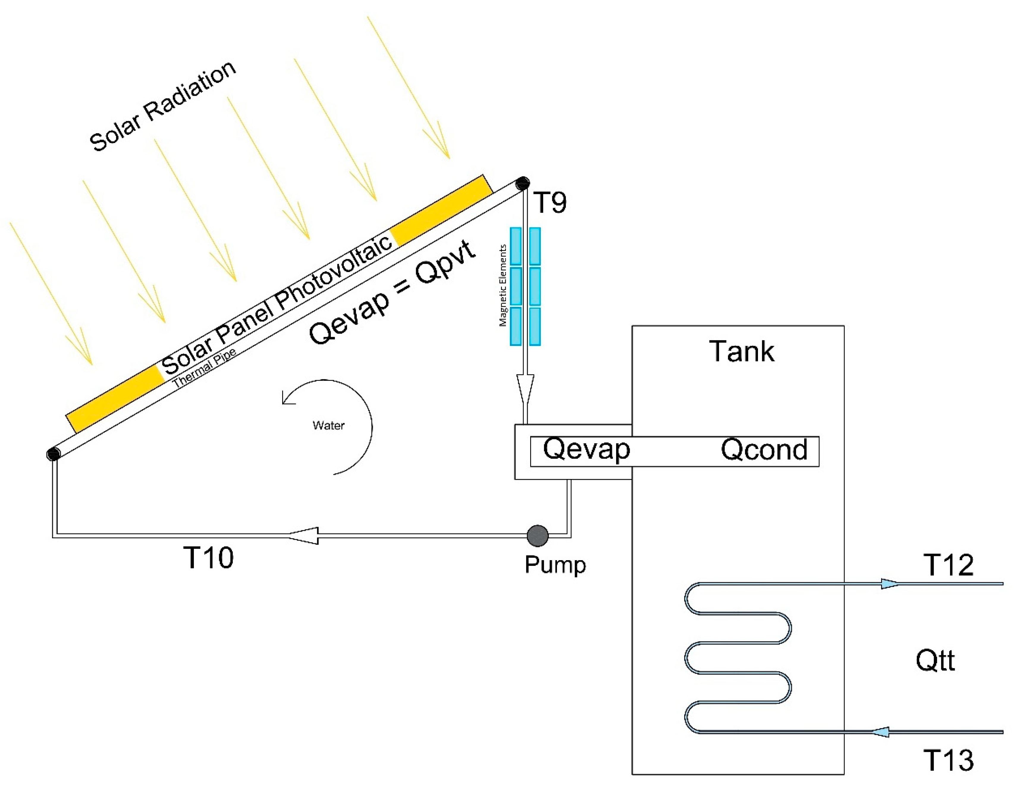
Figure 1 illustrates “the PV-Th integrated solar panel cooled by a water-based nanofluid that was analyzed and numerically modeled in this research work under the influence of magnetic field force. This integrated hybrid system consisted of a photovoltaic solar panel and welded thin parallel tubes on its backside for the circulation of the heat transport fluid with nanofluids. The parallel thin tubes were soldered to the PV solar panel and connected to a thermal tank from which water-based nanofluids flow through the solar collector copper pipes and carry the excess heat away from the PV–thermal panel as shown in
Figure 1. The excess heat released by the PV solar panels was transferred to the evaporator section of the heat pipe and released by the condenser section of the heat pipe in the thermal tank”.
In this study, various water-based nanofluid flow rates were considered and analyzed in different conditions of magnetic field forces to assess their impact on the performance of the PV–thermal heat pipe hybrid system. “This hybrid system was intended for power generation by the PV solar panels and using the thermal excess heat transferred and heat pipes to produce hot water for domestic and/or industrial use. Additionally, the model in question examined the enhancement in the hybrid system efficiency of the solar PV panel at various operating temperatures”. The model is presented in the following sections.
2.1. PV Model
The solar photovoltaic panel is constructed of various modules and each module consists of arrays and cells. The dynamic current output can be obtained as follows [
19,
20,
21,
22,
23]:
Ip: Output current of the PV module
IL: Light generated current per module
Io: Reverse saturation current per module
V: Terminal voltage per module
Rs: Diode series resistance per module
Rsh: Diode shunt resistance per module
q: Electric charge
k: The Boltzmann constant
A: Diode ideality factor for the module
The PV cell temperature, Tc, is influenced by various factors such as solar radiation, ambient conditions, and wind speed. It is well known that the cell temperature impacts the PV current and performance, and its time variation can be determined from references [
19,
20,
21,
22,
23]. The current of the PV module, light generated current, and reverse saturation current are obtained according to references [
19,
20,
21,
22,
23]. Readers interested in the calculations of the different parameters in Equation (1) are advised to consult the aforementioned references.
The AC power of the inverter output of the PV solar panel circuit,
P(
t), is calculated using the inverter efficiency,
ηinv, output voltage between phases, neutral
Vfn, and for a single-phase current,
Io and cos
φ, as follows:
2.2. PV Thermal Model
In the following thermal analysis, it is assumed that all PV cells behave the same; therefore, it is applied to the PV solar panel.
The heat absorbed by the PV solar cell can be calculated by the following [
18,
19,
20,
21,
22,
23]:
where:
αabs: Overall absorption coefficient
G: Total solar radiation incident on the PV module
Sp: Total area of the PV module
Meanwhile, the PV cell temperature is computed from the following heat balance [
18,
19,
20,
21,
22,
23]:
where:
TC: PV cell temperature
mCp_module: Thermal capacity of the PV module
t: Time
Qin: Energy rate received due to solar irradiation
Qconv: Energy rate loss due to convection
Qelect: Electrical rate power generated
Additionally, the solar energy absorbed by the PV cell, Qin, is given by Equation (3).
2.3. Thermal Energy Incident in a PV Cell
The energy loss due to heat convection can be obtained from:
H: Convective heat transfer coefficient
Ta: Ambient temperature
The electrical power generated is given by:
η: Module efficiency
Sc: Total surface area of PV cells in a module
The thermal energy transferred from the PV cells to the heat transfer fluid (HTF) is determined from the heat balance across the PV cell and HTF in terms of the heat transfer mechanisms, conduction, convection, and radiation, as follows [
1,
17,
18,
19,
20,
21,
22,
23]:
The heat transfer by conduction is calculated as follows:
Tm: Module back-surface temperature
KPv: Thermal conductivity of PV cell
Lcell: Length of a PV cell
To close the energy balance in Equation (7), the heat transfer by convection and by radiation is determined, respectively, using the convection heat transfer coefficient and emissivity PV cell Stefan–Boltzmann constant. Readers interested in the calculation of the heat balance in Equation (7) are advised to consult Sami [
23].
The finite-difference formulation was used to determine the heat transfer fluid temperature as follows for each element using the following equation. The heat transfer fluid tube is divided into
nTE elements:
t: Time
Tf_in: Fluid temperature at the inlet and t represents the time step iteration
The thermal energy transferred from the PV cell to the heat transfer fluid is obtained by:
QThermal: Energy from the thermal process
TfHx+1: Fluid temperature at thermal element 1
The energy transferred to heat transfer fluid is calculated by the integration of the aforementioned equations along the length of each tube. In this analysis, the mainstream temperature of the heat transfer fluid flow was considered as the average temperature of the inlet and outlet of each finite-difference element:
ṁw: Water flow
Tf+1: Water temperature at the next element
Cp: Specific heat of HTF
Finally, the PV–thermal hybrid system energy conversion efficiency for harnessing energy from solar radiation is given:
where
Qth and
Qin are the solar thermal heat transferred to the HTF and solar irradiance. The respective values are given by Equations (1) and (12). In addition,
P(t) is the PV solar electrical output and is defined by Equation (2).
2.4. Nanofluid Heat Transfer Fluid
The basic heat transfer fluid in the PV–thermal loop, as shown in
Figure 1, is water-based nanofluid. Nanofluids were added to the water-based flow to enhance their thermal properties. “References [
14,
15,
16,
17,
18,
19,
20,
21,
22,
23,
24,
25,
26,
27,
28,
29,
30,
31,
32,
33,
34] presented equations to calculate the thermophysical and thermodynamic properties of nanofluids such as specific heat, thermal conductivity, viscosity, and density by employing the law of mixtures, as a function of the volumetric concentration of nanoparticles”:
where
α represents a particular thermophysical property of the nanofluid under investigation.
The nanofluid thermal and thermophysical properties,
αtotal, can be calculated as follows:
where Φ represents the nanoparticles’ volumetric concentration.
The thermal conductivity is related to thermal diffusivity and density of the nanofluids as follows:
where
Cp is the specific heat,
α is the thermal diffusivity,
λ and
ρ represent the thermal conductivity and density, respectively.
The specific heat is calculated for nanofluids as follows [
14,
15,
16,
17,
18,
19,
20,
21,
22,
23,
24,
25,
26,
27,
28,
29,
30,
31]:
where “
nf” and “
bf” refer to nanofluid and basic fluid, respectively. Ø is the nanofluid particle concentration.
ρ represents the density.
The density of nanofluids can be written as follows [
14,
15,
16,
17,
18,
19,
20,
21,
22,
23,
24,
25,
26,
27,
28,
29,
30,
31]:
ρp represents the density of the nanoparticles.
2.5. Thermophysical Properties with Magnetic Field
“Magnetorheological heat transfer nanofluids are smart materials made of magnetic particles that can enhance flow characteristics in the presence of a magnetic field. However, the field-dependent thermal conductivity of magnetorheological fluids plays an important role in heat transfer and dissipation in potential new applications. Reference [
54] reported that magnetic nanofluids with a low concentration of nanoparticles can significantly enhance their thermal energy”. This research considered that magnetic metallic solids under different magnetic Gauss forces improve thermal and thermophysical properties compared to fluids, and nanofluids exhibit significantly better thermal properties compared to conventional heat transfer fluids. In the following, we present the formulas developed for predicting the thermophysical properties of nanofluids [
54]. The magnetic data published in the literature [
10,
11,
12,
13,
14,
15,
16,
17,
18,
19,
20,
21,
22,
23,
24,
25,
26,
27,
28,
29,
30,
31] were used to take into account the impact of the magnetic field, as outlined in
Table 1.
Where “b” represents the nanofluid specific property and “a” is the magnetic field force in Gauss. Cpnf, Knf, and h are the specific heat, thermal conductivity, and heat transfer coefficients of nanofluids.
Equation (17) can be used to determine other thermophysical properties, where α is the thermal diffusivity and
λ and
ρ represent the thermal conductivity and density as a function of the properties outlined in
Table 1.
2.6. Heat Pipe Model
The proper function of the heat pipe depends upon the pressure drop in the fluid flow embedded in the heat pipe that has to be compensated by the pumping pressure in the wick and the capillarity, as prescribed by Sami [
16,
31], Tardy and Sami [
33], Endalew [
19], and Reay and Kew [
32]:
where ∆
Pp, ∆
Pl, ∆
Pv, and ∆
Pg are the total pumping pressure, pressure drop for liquid return from the condenser, pressure drop for vapor flow in the evaporator, and gravity head, respectively.
“The heat transfer limit for a heat pipe depends on the construction of the heat pipe and the operating environment. The design of the heat pipe and the wick properties are determined by the thermophysical properties of the working fluid used [
32]. The heat pipe heat transfer capillary, sonic, entrainment, boiling, frozen start-up, continuum vapor, vapor pressure, and condenser effects determine the physical phenomena that establish the lowest limit of these phenomena and are considered as a design limit. The main design limitations were extensively discussed in Tardy and Sami [
33], Reay and Kew [
32], Tardy and Sami [
34], and Sami [
16]”. Readers interested in the capillary, sonic, entrainment, and boiling limits of the heat pipes are advised to consult the aforementioned references and others reported in the literature.
“Several factors are considered in selecting the working fluid inside the heat pipe, in particular, the working fluid temperature range is an important criterion to be fulfilled. Refrigerants and refrigerant mixtures are widely used as working fluids for low-temperature heat pipe applications because of lower vapor pressure and boiling points”.
“The energy conversion and efficiency of heat transfer from the evaporator section of the heat pipe to the condenser section in the solar application is one of the most important selection criteria for the working fluid. Hence, the use of working fluid with higher latent heat is very beneficial to applications of heat pipes in solar energy conversion”. Water and different refrigerants, such as R-134a, R-123, R-32, R-125, R-152a, R-1234ze, and R-1234fz, as well as refrigerant mixtures [
38], are considered in this investigation as working fluids inside the heat pipe.
“A heat pipe using two-phase thermosyphon principles has been reported in the literature by Endalew [
19] in water heating applications. References [
14,
15,
16,
17,
18,
19,
20,
21,
22,
23,
24,
25,
26,
27,
28,
29,
30,
31,
32]” are also discussed. In the current study, the “two phases were in forced convective condensers under either a crossflow or parallel flow pattern. In this study, the thermosyphon condition was under consideration, as illustrated in
Figure 1. The condenser section of the heat pipe was placed in a thermal storage tank where natural convective heat transfer took place. It was assumed that the condensing water flow in the thermal tank was stagnant, and there was no temperature gradient along the axis of the heat pipe”.
The energy balance under a natural convection heat transfer condition in the thermal storage tank, as per
Figure 1, using a single control volume of heat pipe submerged in the thermal tank, is presented in Equation (18) [
13,
16]:
where
Vw represents the water volume in the thermal tank and
Utan and
Atan are the overall heat transfer coefficient in the thermal tank and the equivalent heat transfer area in the tank, respectively. In addition,
Thp,
Tw, and
Ta are the temperatures of the heat pipe, water, and ambient air.
On the other hand, the effective heat transfer coefficient
heff of the condenser section of the heat pipe can be given by the following [
13,
16]:
where
hf is the natural heat transfer coefficient
hf between the water and the condenser in the thermal tank,
δhp represents the thickness of the heat pipe material, and
khp is the thermal conductivity of the working fluid in the heat pipe.
Additionally,
hcond represents the film condensation heat transfer coefficient and can be obtained from the following correlation suggested by references [
13,
25,
26,
27,
28] and using the Nusselt equation:
where
Thp,
Tw, represent the temperatures of the heat pipe and the water in the tank, respectively, and
ρl,
ρr are the liquid and vapor densities of the working fluid inside the heat pipe, respectively. Additionally,
μl,
di are the viscosity and internal diameter of the heat pipe, respectively.
The natural heat transfer coefficient, h
f, between the water in the thermal tank and the condenser section of the heat pipe, can be developed using the Nusselt equation [
13,
14,
15,
16,
17,
18,
19,
20,
21,
22,
23,
24,
25,
26,
27,
28,
29,
30,
31,
32] as follows:
where
do represent the outside diameter of the condenser section of the heat pipe and
Cp is the specific heat of the working fluid inside the heat pipe. Additionally,
γ is the specific heat ratio.
μ represents the liquid viscosity of the working fluid.
To determine the heat capacity of the condenser section of the heat pipes, the following energy and mass balance equations are considered:
where
Io is the length of the condenser section of the heat pipe.
The efficiency
η of the heat exchanger section of the heat pipes can be calculated as:
On the other hand, the thermal energy dissipated into the thermal tank from the heat pipes and delivered to the domestic or industrial end user is:
where the
represents the water mass flow rate circulating between the thermal tank and the user application in question.
T12 and
T13 are the supply and return temperatures for the end user application, respectively.
ηhx is the thermal tank efficiency.
The water mass flow rate for supplying thermal energy to the end user application is:
The efficiency of the solar PV panels can be expressed as follows:
where
Qelec is calculated by Equation (2) and
Qcollector is obtained by Equation (3).
The thermal efficiency of thermal energy transferred to the evaporator section of the heat pipe is:
where
Qth is calculated by Equation (10).
The thermal efficiency of the heat pipe can be obtained by the following equation:
where
represents the heat released by the condenser section of the heat pipe and
where
Qth is calculated by Equation (23) and
ƞ is the thermal efficiency of the heat exchanger where the evaporator section of the heat pipes is placed.
Finally, the hybrid system energy conversion efficiency for harnessing energy from solar energy using the thermal panels and heat pipe can be formulated as
where
Qelec is calculated by Equation (2)
where
represents the thermal energy released at the condenser side.
4. Results and Discussion
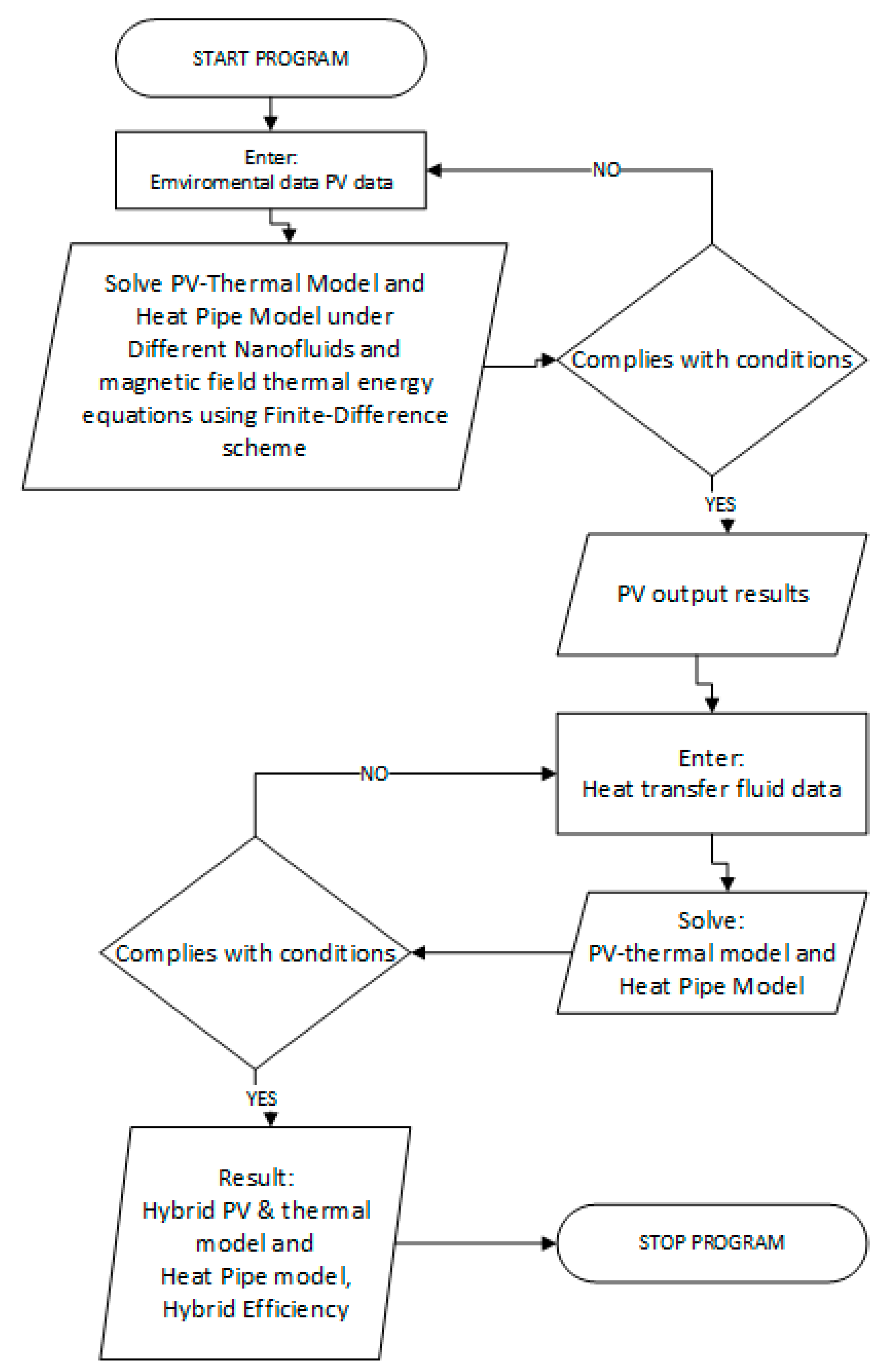
Equations (1)–(31) describing the present numerical model have been solved considering the heat and mass transfer mechanisms during the solar PV–thermal energy conversion process under magnetic field forces and nanofluids. The abovementioned equations were coded with finite-difference formulations and solved as per the logical flow chart depicted in
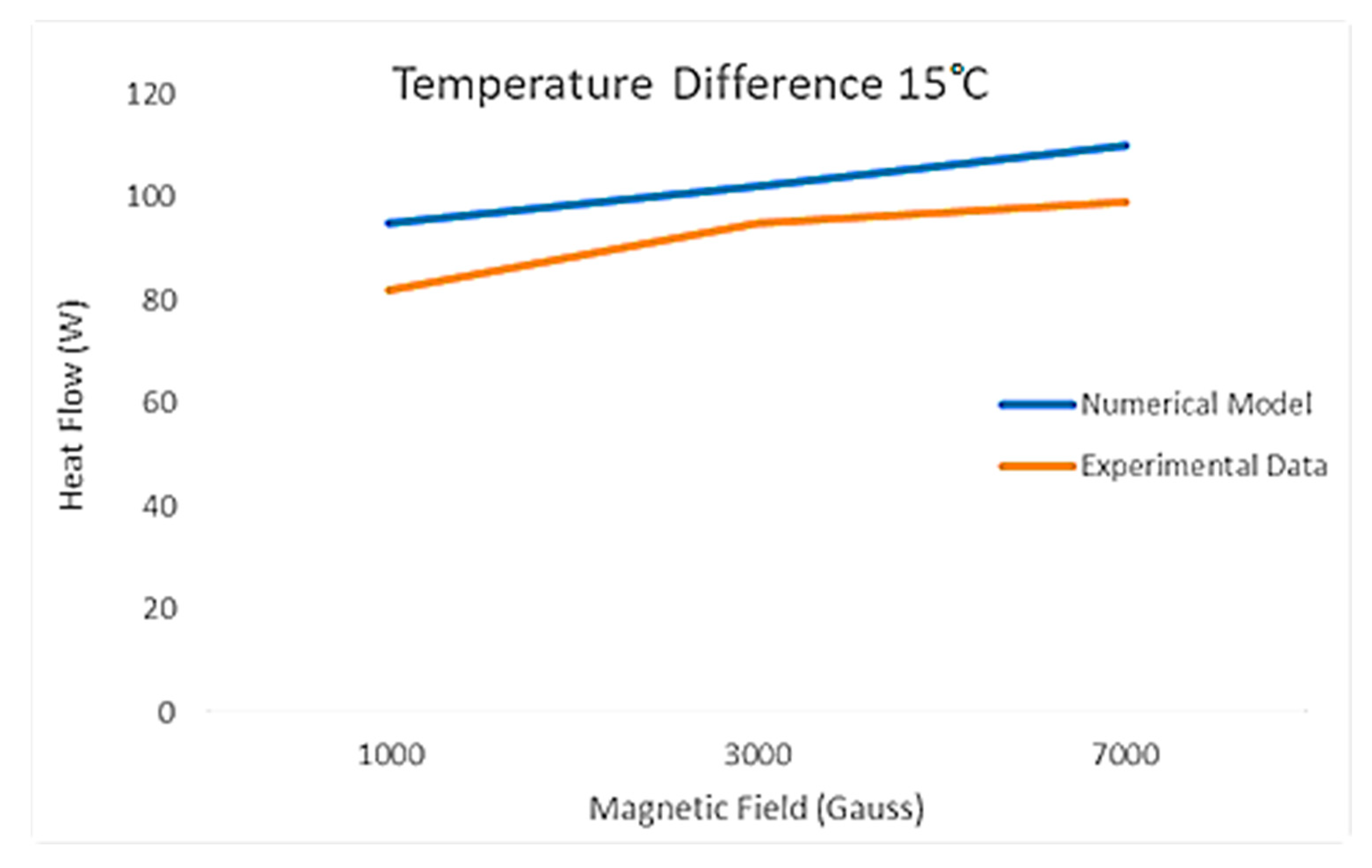
Figure 2. In addition, for validation purposes, the predicted simulated results for PV–thermal solar panels were compared to the data published in the literature under various conditions.
In the following sections, “we present analysis and discussions of the numerical results predicted as well as validations of the proposed simulation model. The simulations were performed with various temperature differences across the thermal tubes of the heat exchanger welded beneath the PV solar panels, however, only results for the temperature difference of 15 °C across the thermal tube are presented and analyzed. It is worthwhile noting that the numerical simulation presented here was conducted under different conditions, such as PV cell temperatures from 10–38 °C, ambient temperatures from 10 °C through 38 °C, solar radiations of 500, 750, 1000, and 1200 w/m2, different nanofluids (Al2O3, Fe3O4, SiO2, and CuO) at various concentrations (5%, 10%, and 20%), and under a magnetic force that varied from 127 to 3000 Gauss. However, in the following, we present discussion and analysis for the nanofluid concentration of 5% for practical reasons to avoid the high-pressure drop and losses in the PV–thermal solar collector loop in practical applications”.
The PV panel characteristics under consideration in this study were obtained from Fargali et al. [
35]. “The parameters adopted in this study were: total surface area of the PV module (SP) is 0.617 m
2, total surface area of cells in module (Sc) is 0.5625 m
2, module efficiency of 12% at the reference temperature (298 K), the overall absorption coefficient is 0.73, and temperature coefficient is 0.0045 K
−1. Readers interested in the full range of values of the other parameters are advised to consult Fargali et al. [
35] and Sami [
31]”.
It was also assumed in this simulation that the whole panel was covered in PV cells, with no packing material (the material used to fill in gaps between the cells on a panel). The PV cells are commercial grade monocrystalline silicon cells with an electrical efficiency of 12% and have a thermal coefficient of 0.54% (1/K) [
31].
As per the equations outlined above, solar radiation increased the PV cell temperature and resulted in an increase in the back cell temperature and, consequently, the heat transport fluid temperature due to the heat transfer from solar energy by conduction and convection as well as radiation, respectively. It has been demonstrated by Sami [
31] that the higher the cell temperature, the higher the back cell and fluid temperatures, and the higher the solar radiations, the higher the PV cell temperature and, consequently, the higher the temperature of the cell until it reaches the design temperature. For further details, interested readers are advised to consult Sami [
31].
“The effects of the PV panel operating temperature on the output efficiency have been well documented in the literature [
14,
15,
16,
17,
18,
19,
20,
21,
22,
23,
24,
25,
26,
27,
28,
29,
30,
31,
32], where the increasing temperature of the PV cell decreased the amount of power available. However, it is important to note that the changes in the PV cell temperature caused by solar radiation have a dynamic nature. The PV panel heats up and cools down gradually depending upon the changes in solar radiation in dynamic response and consequently the power output from the PV panel. It was quite evident from the results reported in the literature, namely Sami [
31], that the cell temperatures,” as well as the other ones, increase with the increase in solar radiation. This can be interpreted as per Equation (1) where the dynamic cell temperatures are expressed in terms of the heat balance across the PV cells as per Equations (3) and (4).
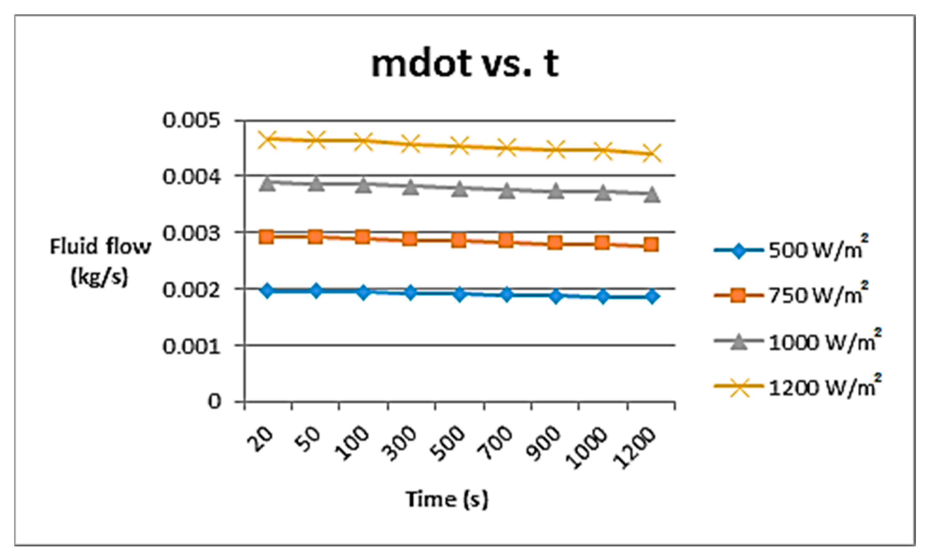
The results presented in
Figure 3 showed that the higher the solar radiation, the higher the thermal energy absorbed and the longer the mass flow rate of the heat transport fluid was reduced. The results also showed, as expected, that the heat transport fluid mass flow rate increased at higher solar radiation. This was because the higher solar radiation resulted in higher thermal energy transferred to the fluid flow and, consequently, this increased the heat transport fluid mass flow rate.
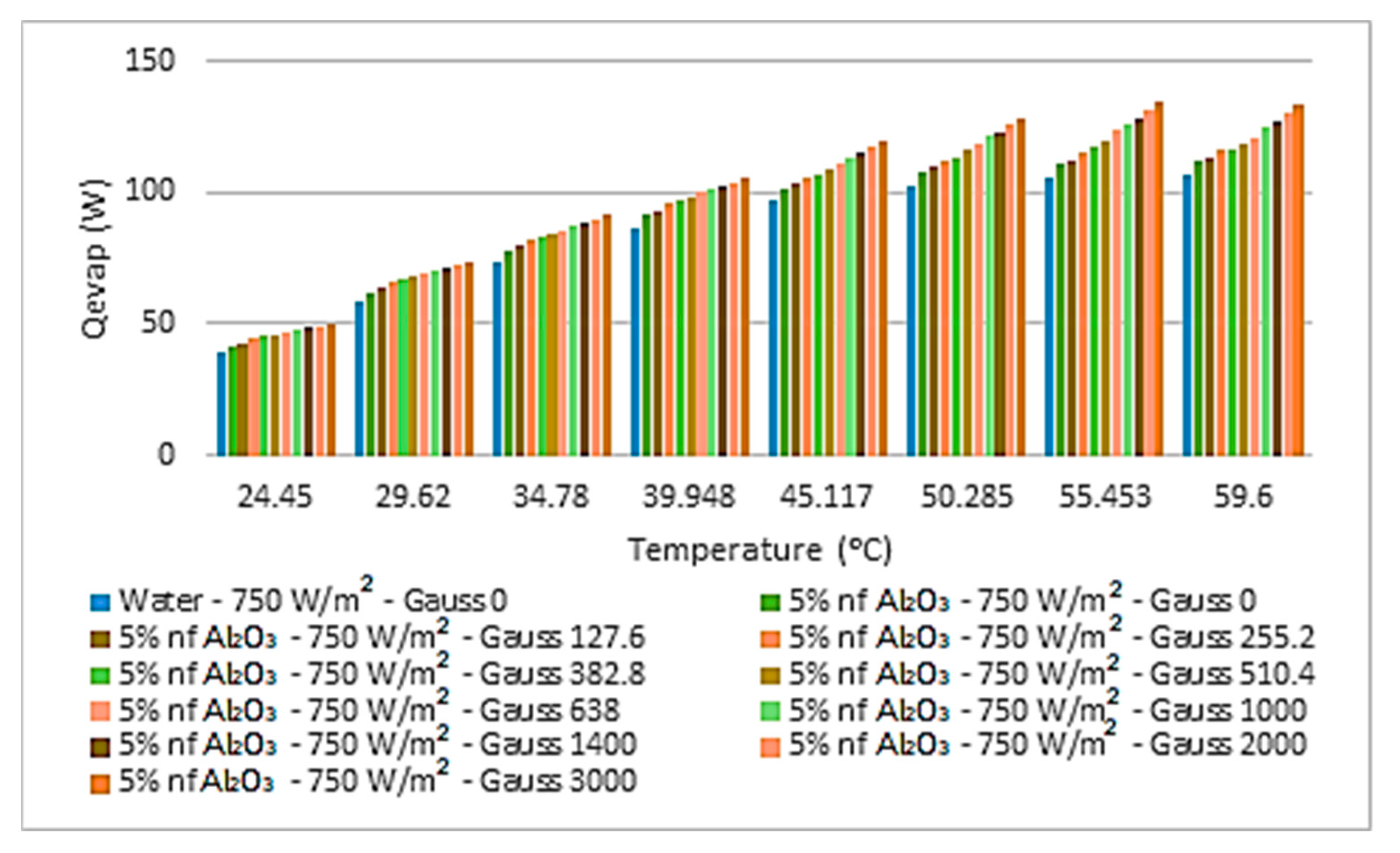
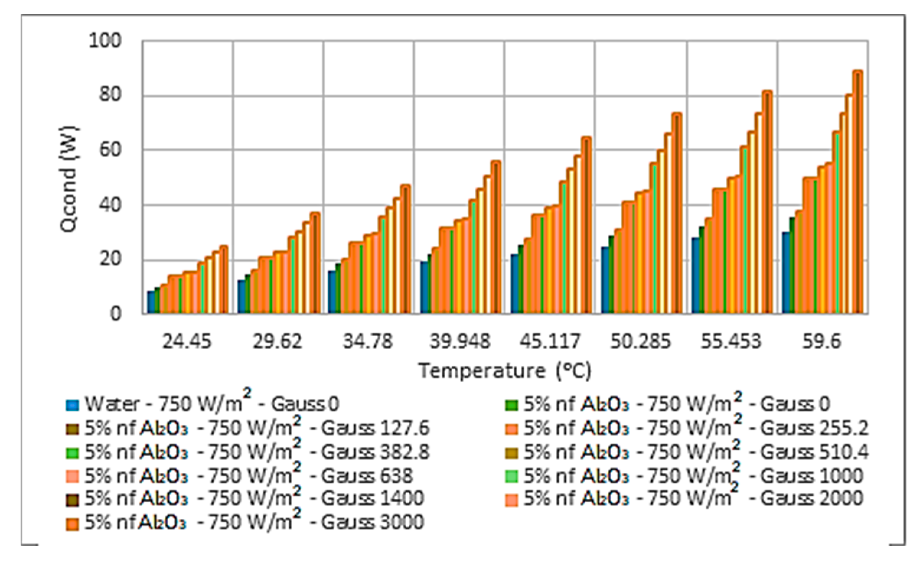
“Al
2O
3 nanofluid was used in this study as a reference base nanofluid because it has been reported the most in the literature for comparison purposes.
Figure 4,
Figure 5,
Figure 6,
Figure 7,
Figure 8,
Figure 9 and
Figure 10 were constructed to analyze the different parameters of the thermal energy converted and transferred to the Al
2O
3 nanofluid heat transport at different temperatures” and a concentration of 5%, circulating beneath the PV-Th solar panel under solar radiation of 750 w/m
2 and at different magnetic fields forces. Additionally, as can be seen from
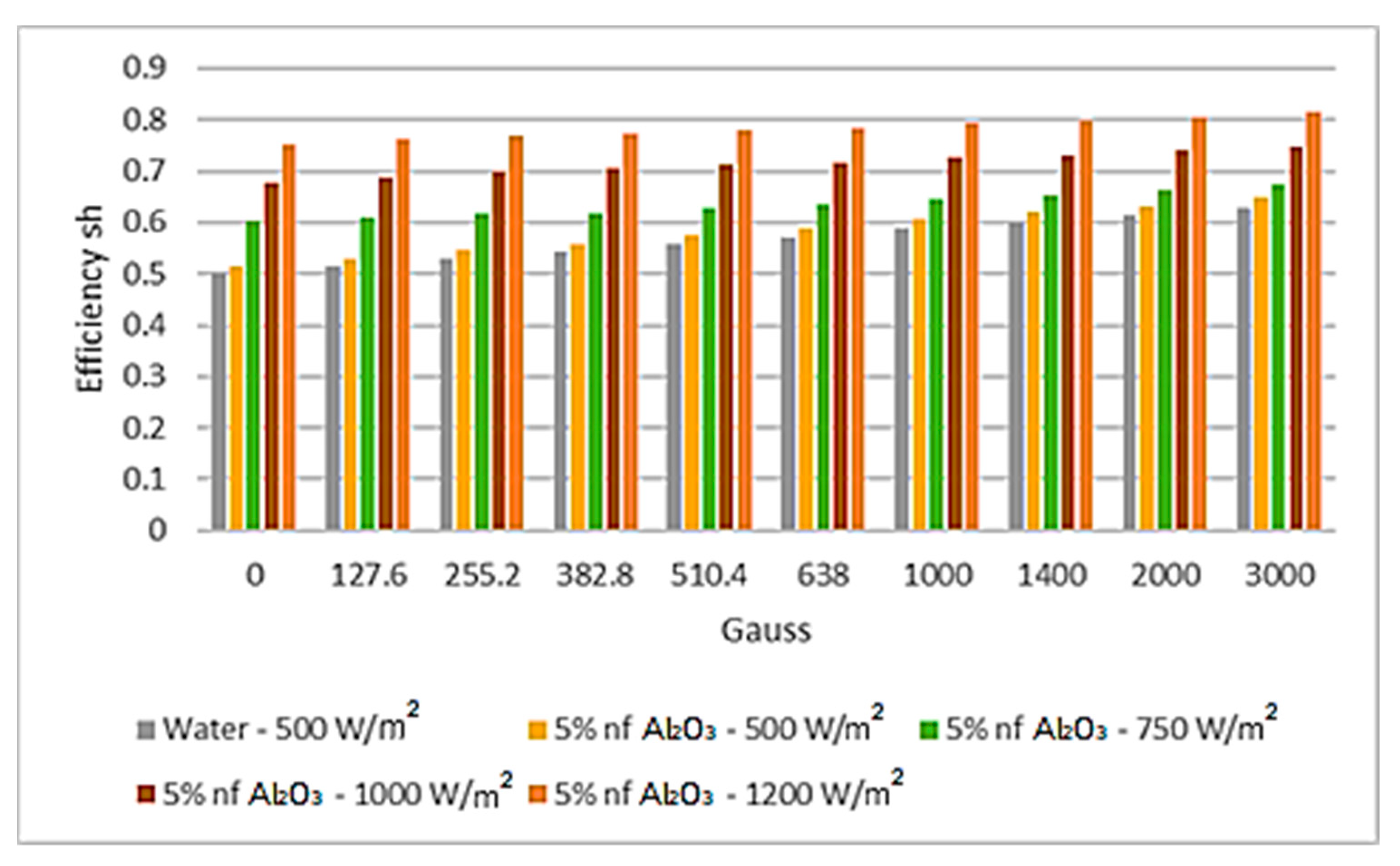
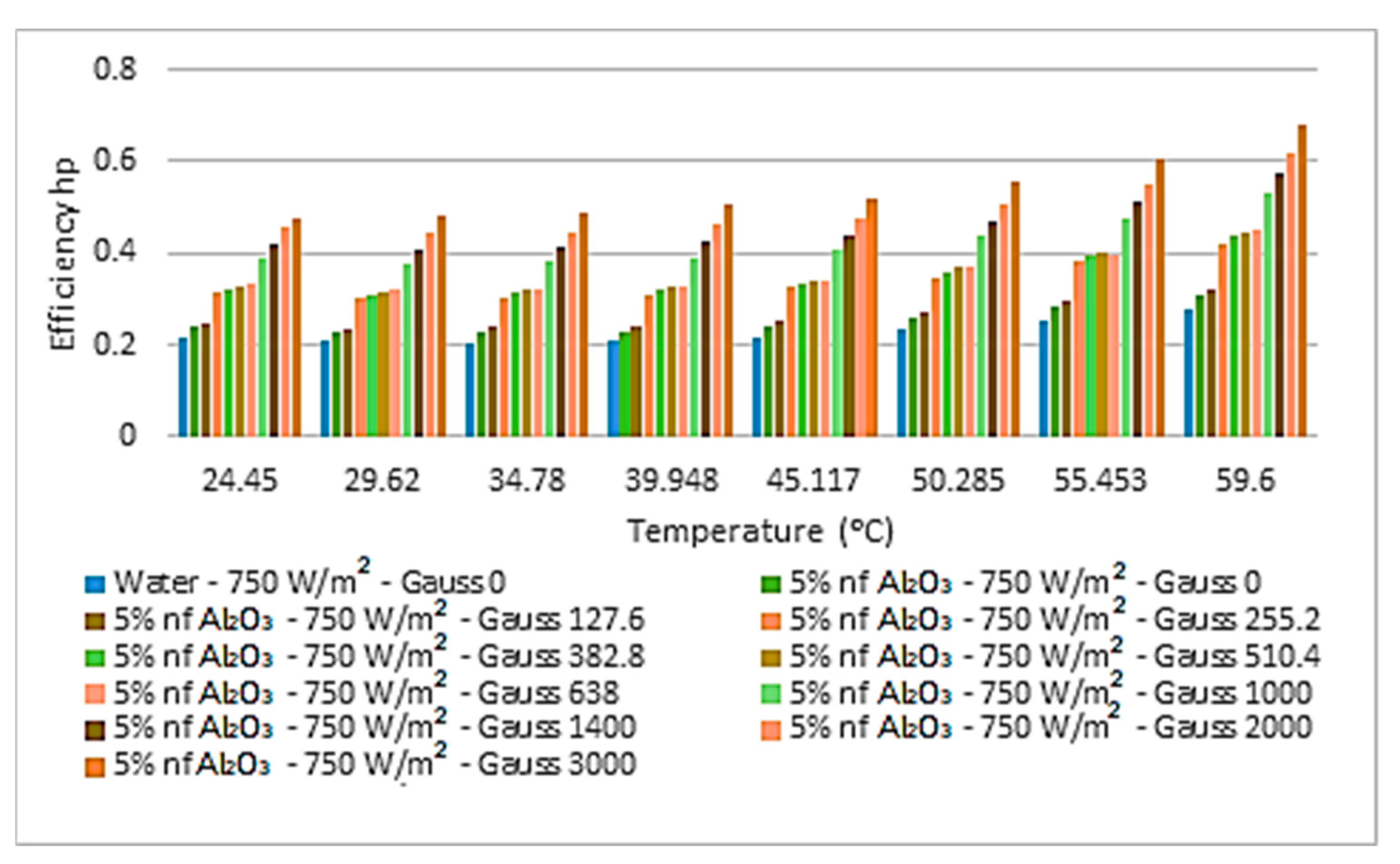
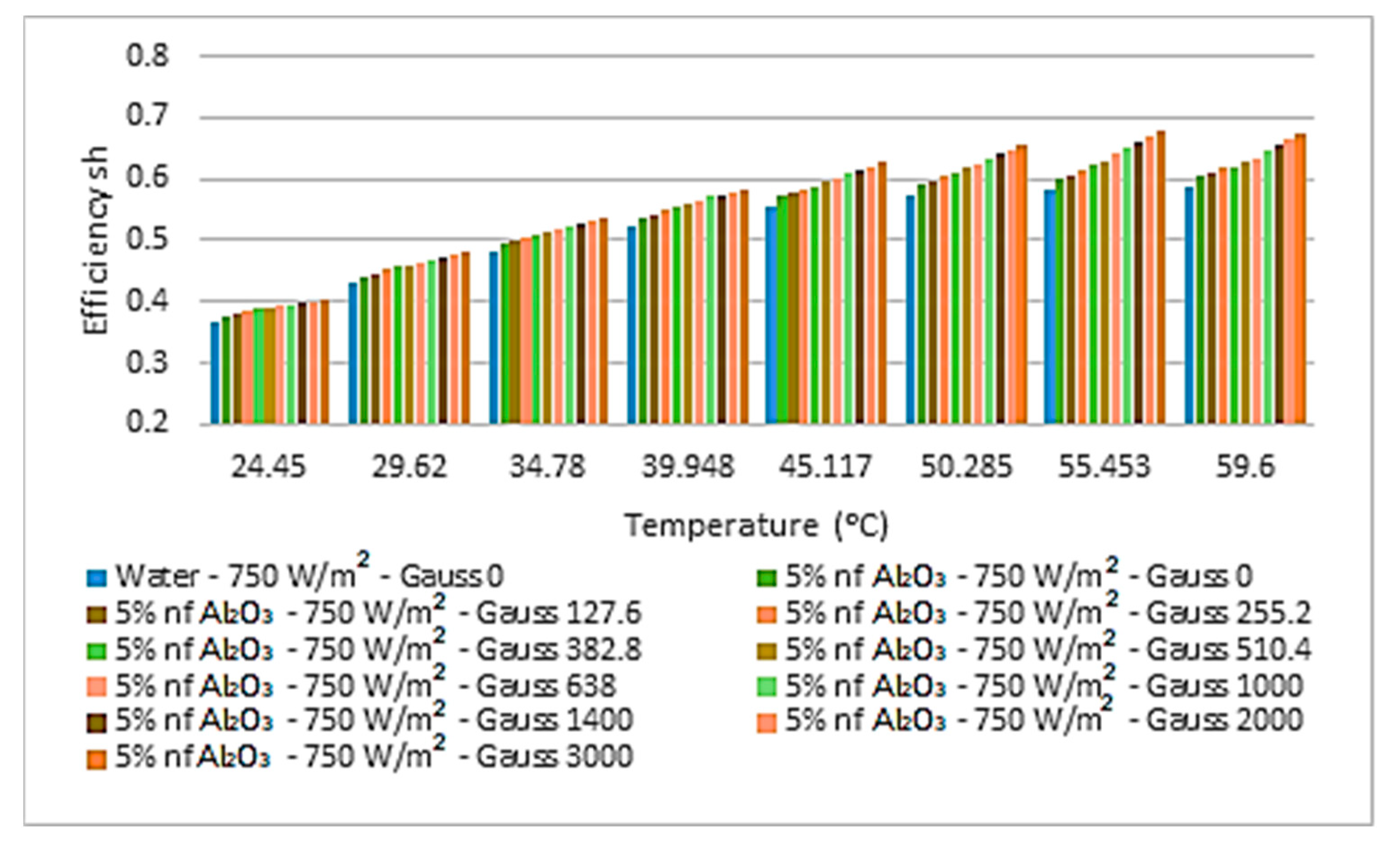
Figure 6, the higher the magnetic field, the higher the thermal energy dissipated from the heat pipe at the condenser side into the storage tank. On the other hand, the hybrid thermal efficiency of the proposed system, as defined in Equation (30), was determined as thermal energy and electrical power generated divided by the solar radiation absorbed by the PV solar panel. It is quite clear from the results presented in
Figure 7,
Figure 8,
Figure 9 and
Figure 10 that the higher the magnetic field, the higher the hybrid thermal conversion efficiency. The results also demonstrated that the higher the magnetic field the higher the heat transport temperatures and the thermal energy transferred to the heat transport nanofluid.
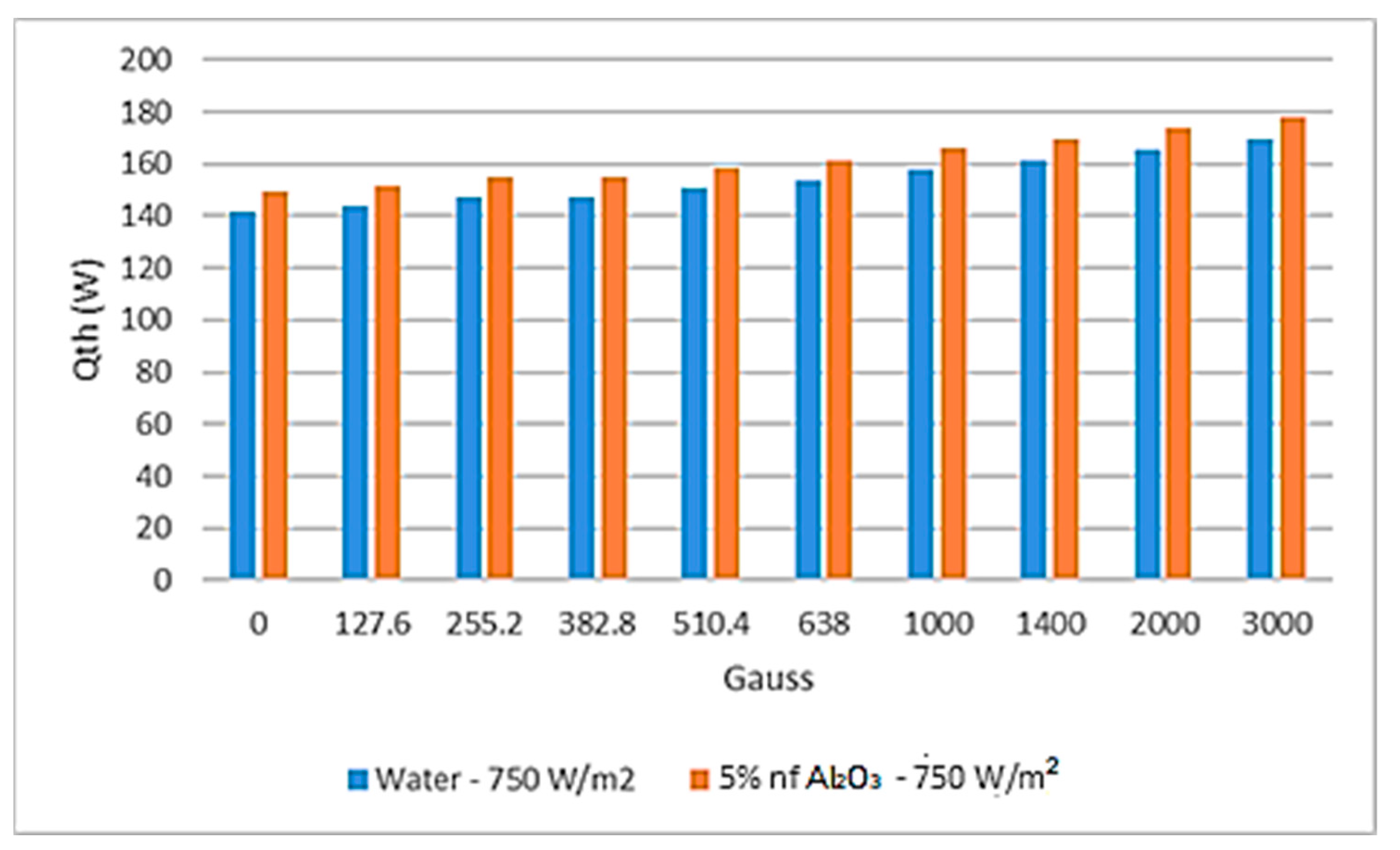
The results depicted in
Figure 4 and
Figure 5 demonstrated that a higher magnetic field force produced higher thermal energy and in turn resulted in higher thermal energy transferred to the heat pipe evaporator section. Finally,
Figure 7 and
Figure 8 show that the higher the magnetic field, the higher the efficiency of the PV–thermal solar panel and the higher the hybrid system efficiency. It also appears from
Figure 9 and
Figure 10 that a higher magnetic field resulted in more thermal energy dissipated in the PV-Th solar panels and affected the hybrid system efficiency.
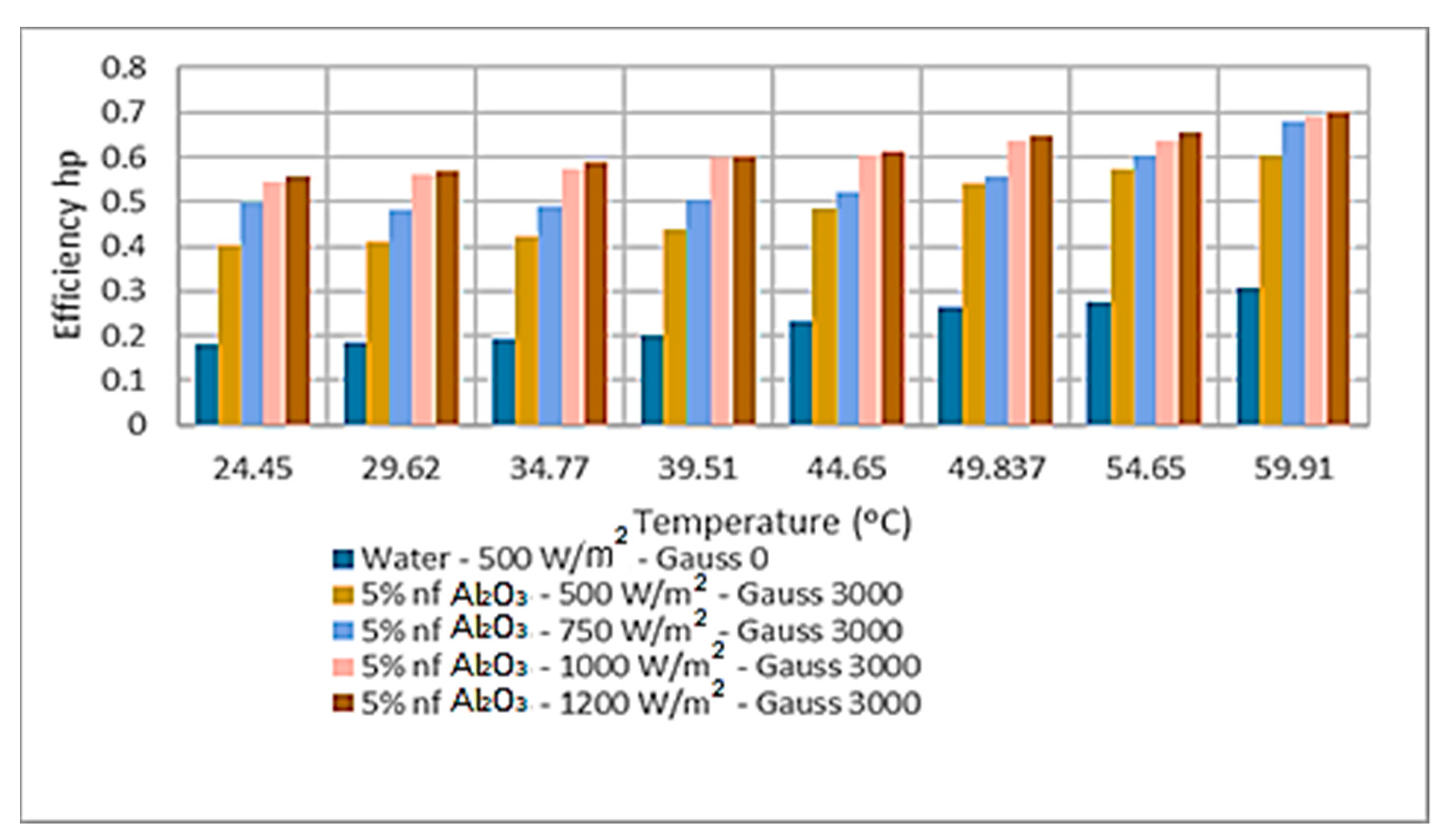
The heat pipe condenser section’s thermal energy calculated by Equation (23) is plotted in
Figure 6 at different heat pipe temperatures. This thermal energy was transferred from the evaporator section of the heat pipes through the heat pipe filled with working fluid and appeared to show dependence upon the magnetic field, however, the higher the heat pipe temperature, the more the heat pipe condenser section’s heat dissipated into the storage thermal tank. “As discussed earlier, a higher magnetic field together with higher solar radiation [
31] enhanced the thermal energy transferred to the nanofluid heat transfer fluid and, in turn, increased the heat transport fluid flow rate and the heat pipe temperature, thus, it can be concluded that the magnetic field indirectly impacted the thermal heat developed in the heat pipe condenser section. This is reflected in the graphical representation of the heat pipe efficiency calculated by Equation (29) and presented in
Figure 7 and shows an increase in the heat pipe efficiency with the heat pipe temperature and the magnetic field”.
Similar observations were noted regarding the other key parameters of the hybrid system in
Figure 4 and
Figure 10 at the different nanofluid concentrations, and in particular, in
Figure 9 and
Figure 10 where it can be seen that the higher the magnetic field, the higher the thermal energy generated and dissipated into the heat transport fluid. Additionally, we noted that the higher the magnetic field, the higher the thermal efficiency of the hybrid system in question compared to the water as base heat transport fluid circulating beneath the PV solar panel. Similar observations have been noted for other nanofluid concentrations (10% and 20%).
It is believed that the aforementioned observations were caused by the enhancement in thermal conductivity of the magnetic nanofluids and can be explained based on the interaction among the dispersed nanoparticles and how the behavior changes in the presence of a magnetic field. “The phenomenon of the enhancement of thermal conductivity can be explained based on chain formation due to particle–particle interactions and alignment along the magnetic field (Yang [
12] and Sami [
21]), which resulted in the formation, conducting, and diffusing of heat. A higher magnetic field charge can cause heat transport water-based nanofluid molecules to be attracted to each other and form clusters when passed through a magnetic field, and some of the physical properties, such as surface tension, viscosity, the dielectric constant, and electrical and thermal conductivity, were changed under the influence of the magnetic field, as reported by Cai et al. [
51], compared to no magnetic field. Pang et al. [
52] also found that the magnetic fields reduced the specific heat, increased the soaking degree and hydrophobicity of water to materials, depressed its surface tension force, and increased the refractive index and electrical conductivity. If the particles are loosely packed within the fibrils, as occurs with low magnetic fields or low concentrations, the effective volume of the fluid in between two consecutive particles within the chains is larger and thereby the chain’s ability to conduct heat is low. As the magnetic field intensity increases, the force of attraction among the nanoparticles is also increased and reaches maxima at CMF. It is also believed that the aforementioned changes caused by the magnetization of the heat transport fluid and its thermophysical properties enhanced the thermal energy transferred to the heat transport fluid and, in turn, increased the PV-Th thermal efficiency as well as the hybrid system efficiency”.
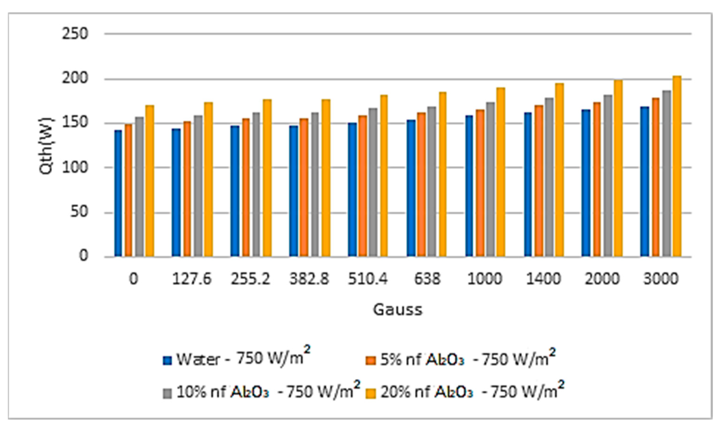
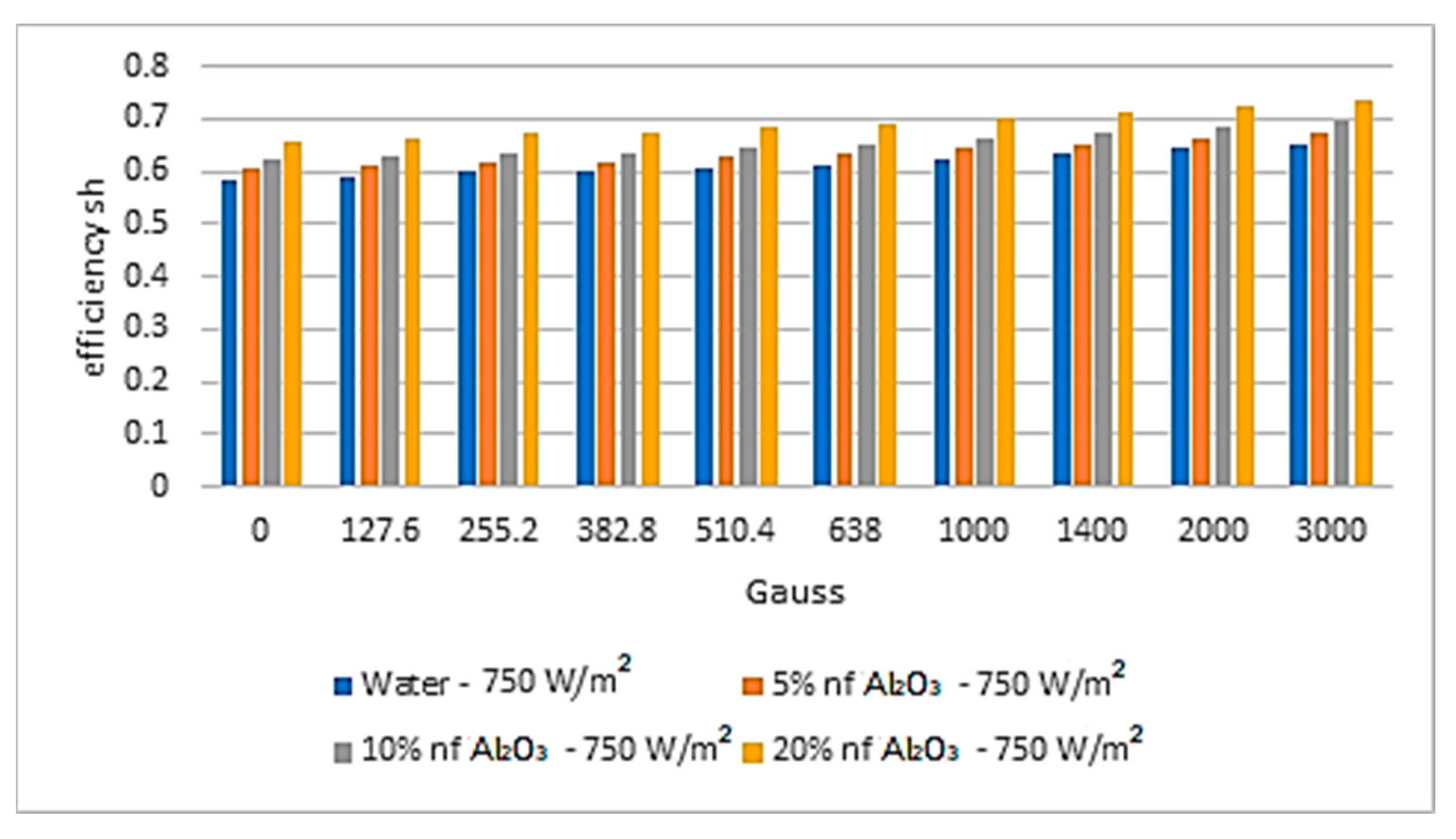
During this investigation, we observed that the nanofluid concentrations have a significant effect on the system’s main characteristics, such as the thermal energy transferred to the heat transport nanofluid and the hybrid system thermal efficiency.
Figure 11 and
Figure 12 have been constructed to illustrate this phenomenon. The results displayed in these two figures confirmed that the higher the nanofluid concentration, the higher the thermal energy transferred to the nanofluid compared to the water-based heat transport fluid. Furthermore, the same phenomena have been observed with the thermal efficiency of the hybrid system where the higher the nanofluid concentrations, the higher the hybrid system efficiency compared to water as the base heat transport fluid. These phenomena have been discussed and elaborated on in the literature, namely in references [
31,
47,
48,
49,
50]. Readers interested in this subject matter are advised to consult these references.
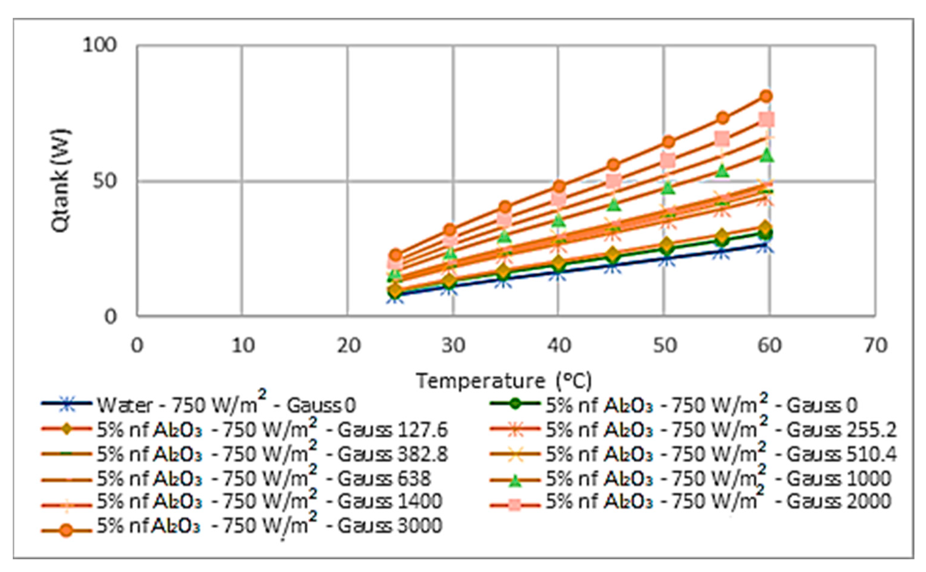
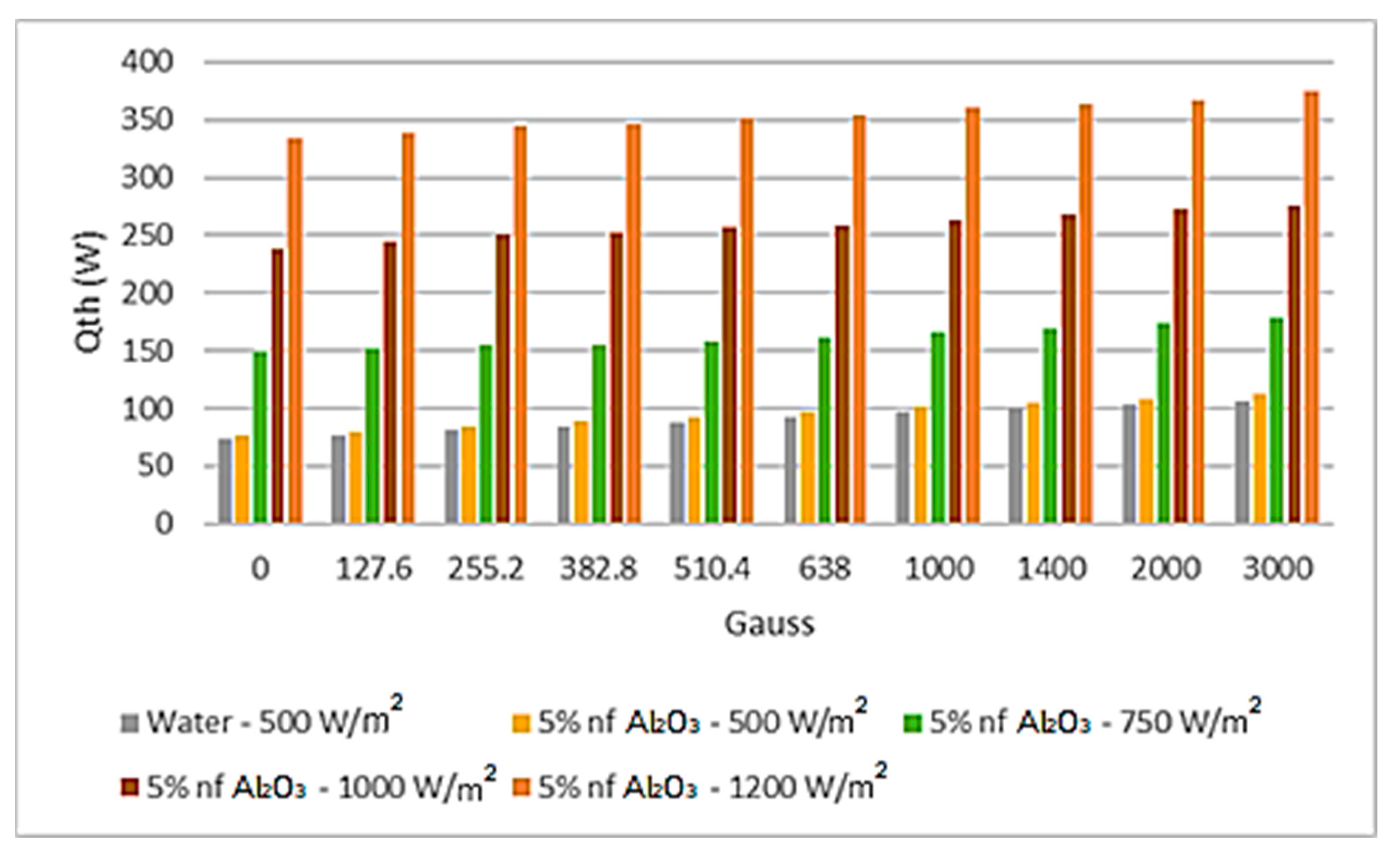
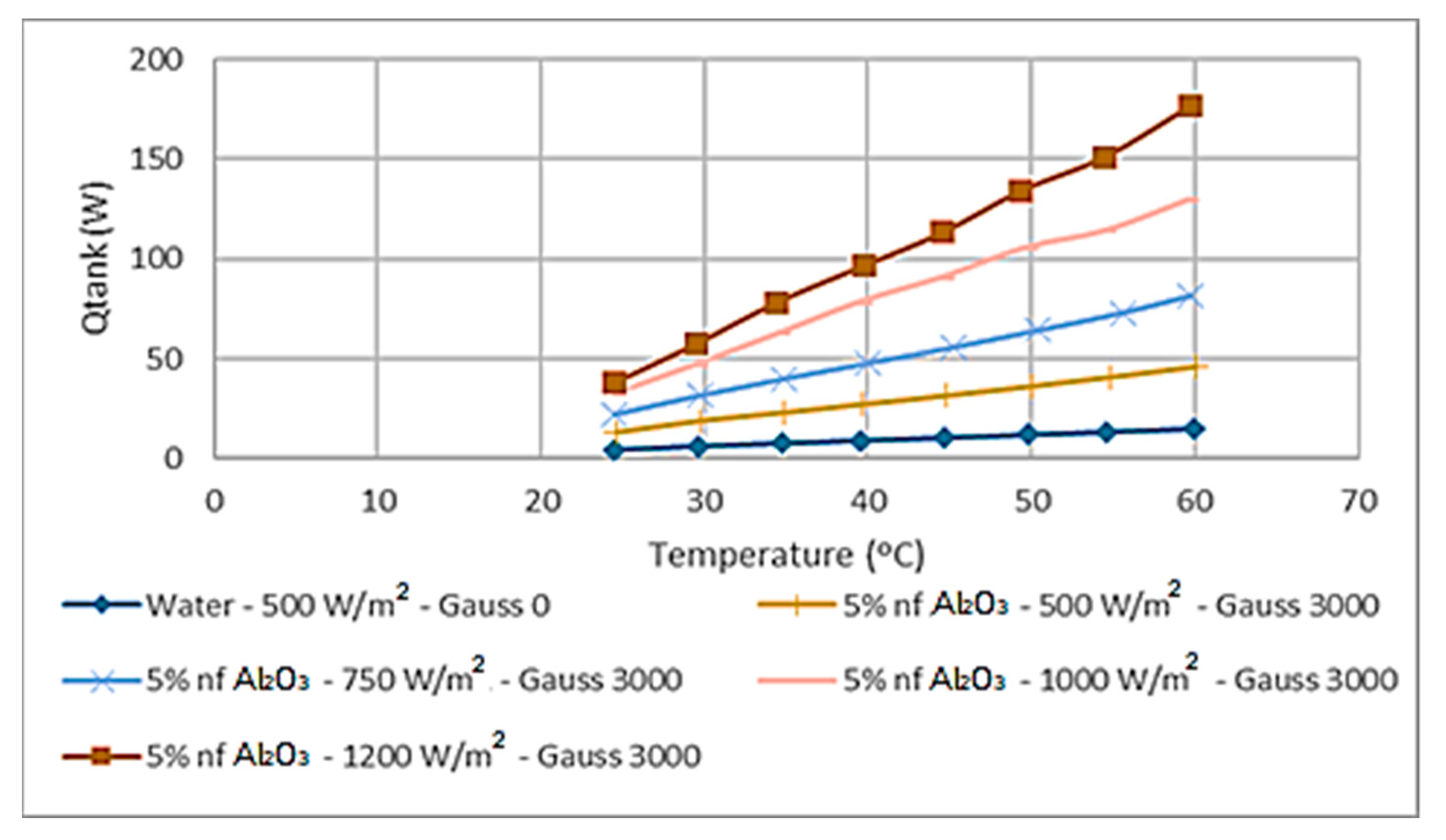
From the end user point of view, the most important parameter is the transfer of the thermal energy to the storage tank to be used for domestic or industrial use. Thus,
Figure 13 is presented to show the impact of the magnetic field on the heat transfer into the storage tank. It appeared from the results obtained at solar radiation of 750 w/m
2 and Al
2O
3 nanofluid at a concentration of 5% that the higher the Gauss magnetic intensity, the higher the thermal energy transferred to the storage tank. Additionally, the results showed that the higher the heat transport nanofluid temperature, the higher the thermal energy transferred to the storage tank. Therefore, as per
Figure 11 and
Figure 12, we can deduce that the higher the nanofluid concentration and the higher the magnetic field, the higher the thermal energy transferred to the storage tank and the higher the hybrid system’s efficiency. This is an important finding to help the designer of such a solar system properly size the hybrid system in question.
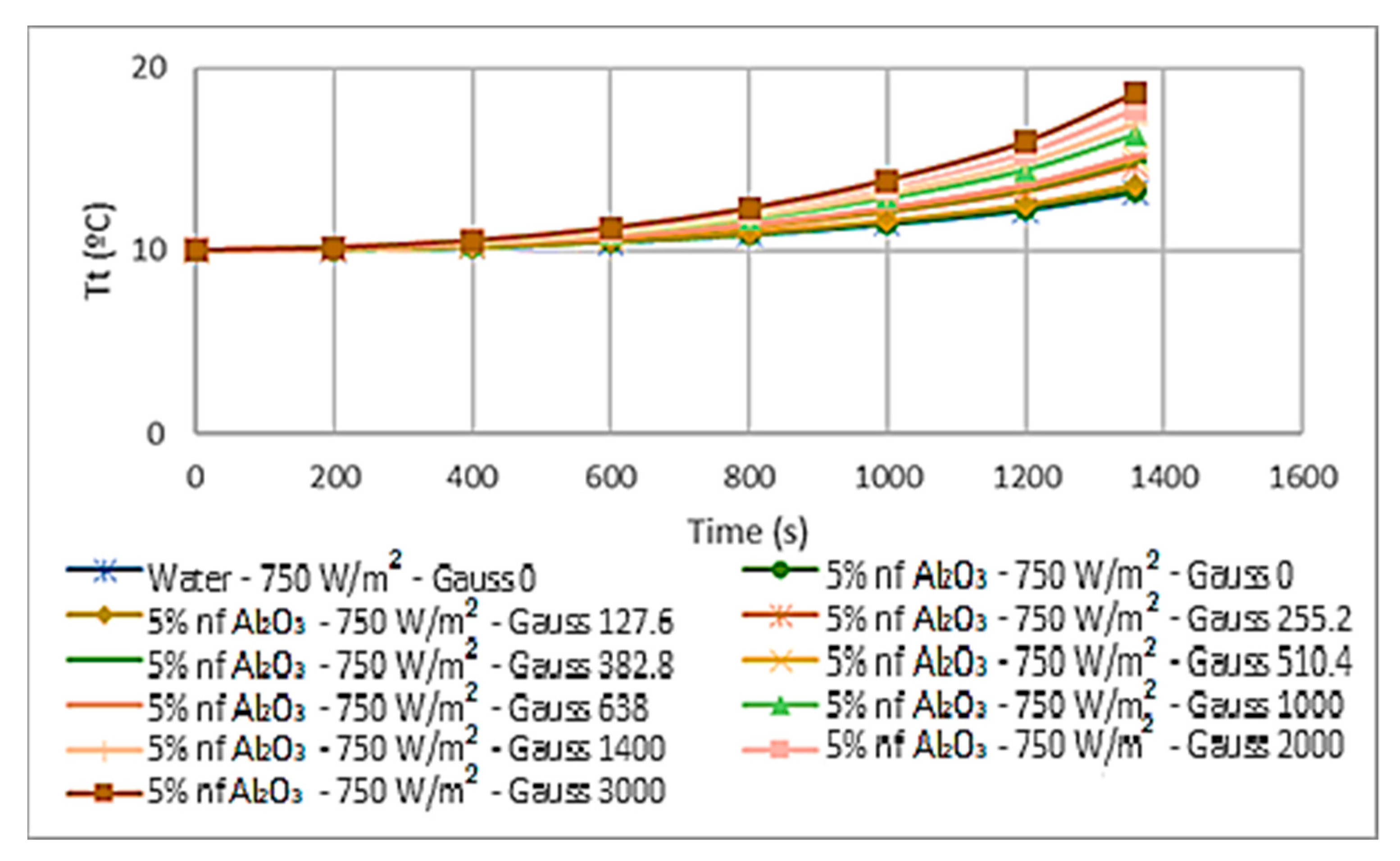
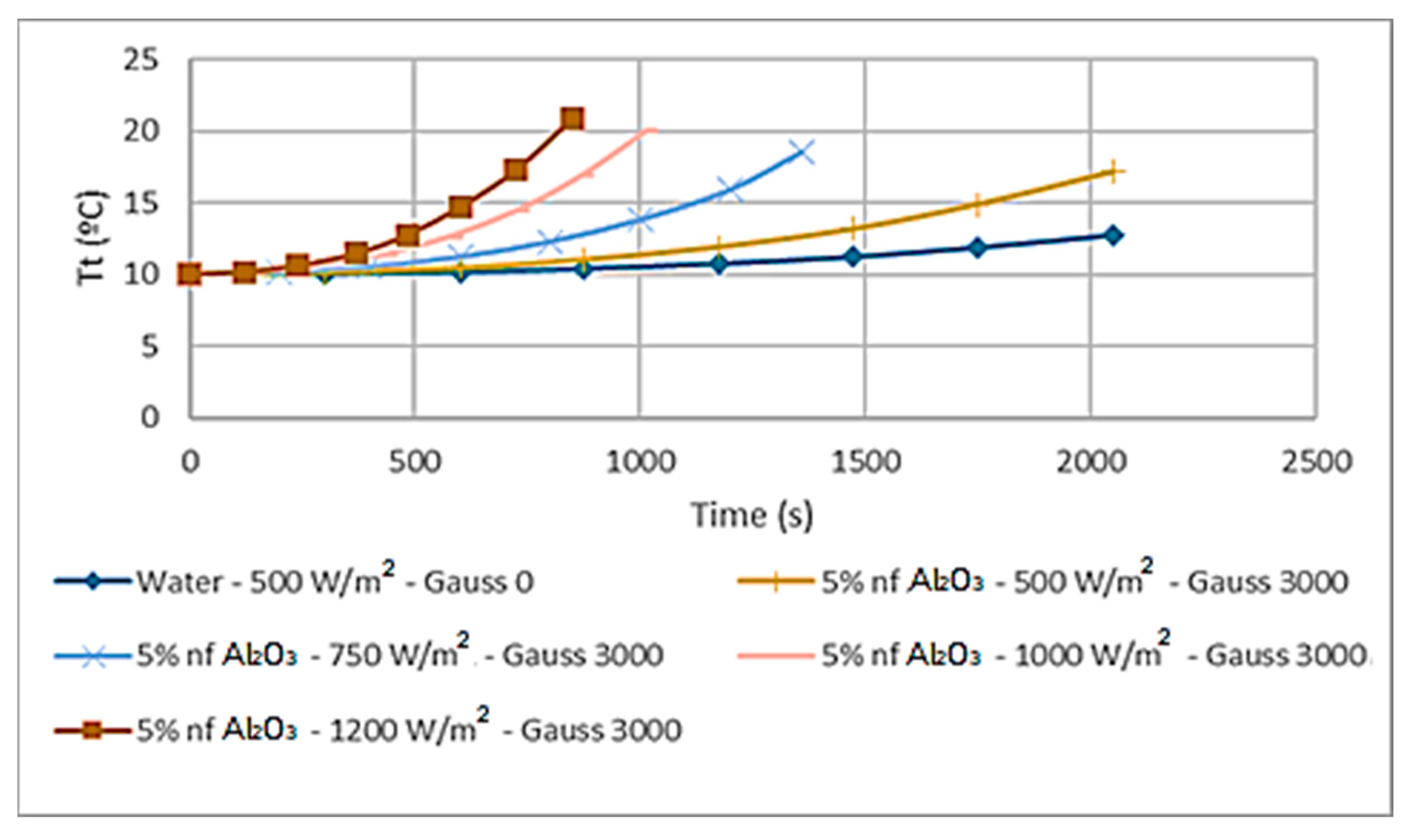
Another angle of this study is to analyze the dynamic development of the storage tank temperature under the increase in the magnetic field, thus
Figure 13,
Figure 14 and
Figure 15 have been plotted to illustrate that increasing the magnetic field resulted in increasing the temperature of the water in the storage tank. In particular,
Figure 14 shows the dynamic temperature–time history. However,
Figure 15 demonstrates that the higher the heat transport fluid temperature, the higher the storage tank temperature. The findings in the aforementioned figure are an extremely useful tool to predict the storage tank characteristics when the heat transport nanofluid is subjected to a magnetic field.
To study the impact of the different solar radiations on the performance of Al
2O
3 nanofluids at a concentration of 5% and magnetic field of 3000 Gauss on the PV-Th solar panels,
Figure 16,
Figure 17,
Figure 18,
Figure 19 and
Figure 20 were constructed and compared with water-based heat transport fluid. The results showed that higher solar radiation increased the thermal energy absorbed and the more heat released to the storage tank, the higher the hybrid system efficiency. In particular,
Figure 18 shows that higher solar radiations resulted in higher heat load in the heat pipe evaporator that also, in turn, enhanced the pipe thermal energy efficiency generated by PV-Th solar panels with different solar radiations. Additionally,
Figure 20 demonstrates that higher solar radiation resulted in higher water temperature in the storage tank which is a result of the increase in the thermal energy in the heat pipe condenser section. It is important to note that similar observations were found at the other different concentrations of the Al
2O
3 nanofluid.
“It is believed that the increase in radiative forcing resulted in higher solar PV panel surface temperatures and an increase in the water-holding thermal capacity that, in turn, increased the thermal energy transferred to the heat transport nanofluid and the hybrid system efficiency. This was interpreted by Sami [
31] and others that as temperature increases, both the number of free electrons and lattice vibrations increase. Additionally, the fluid molecules’ spatial velocity increased at higher temperatures, thus, heat is transferred through the material at a higher rate. Thus, the thermal conductivity of the metal is enhanced and the thermal conductivity increases drastically as the temperature increases (see Sami [
31]). Readers interested in this phenomenon should consult references [
9,
31,
42,
43,
44,
45]”.
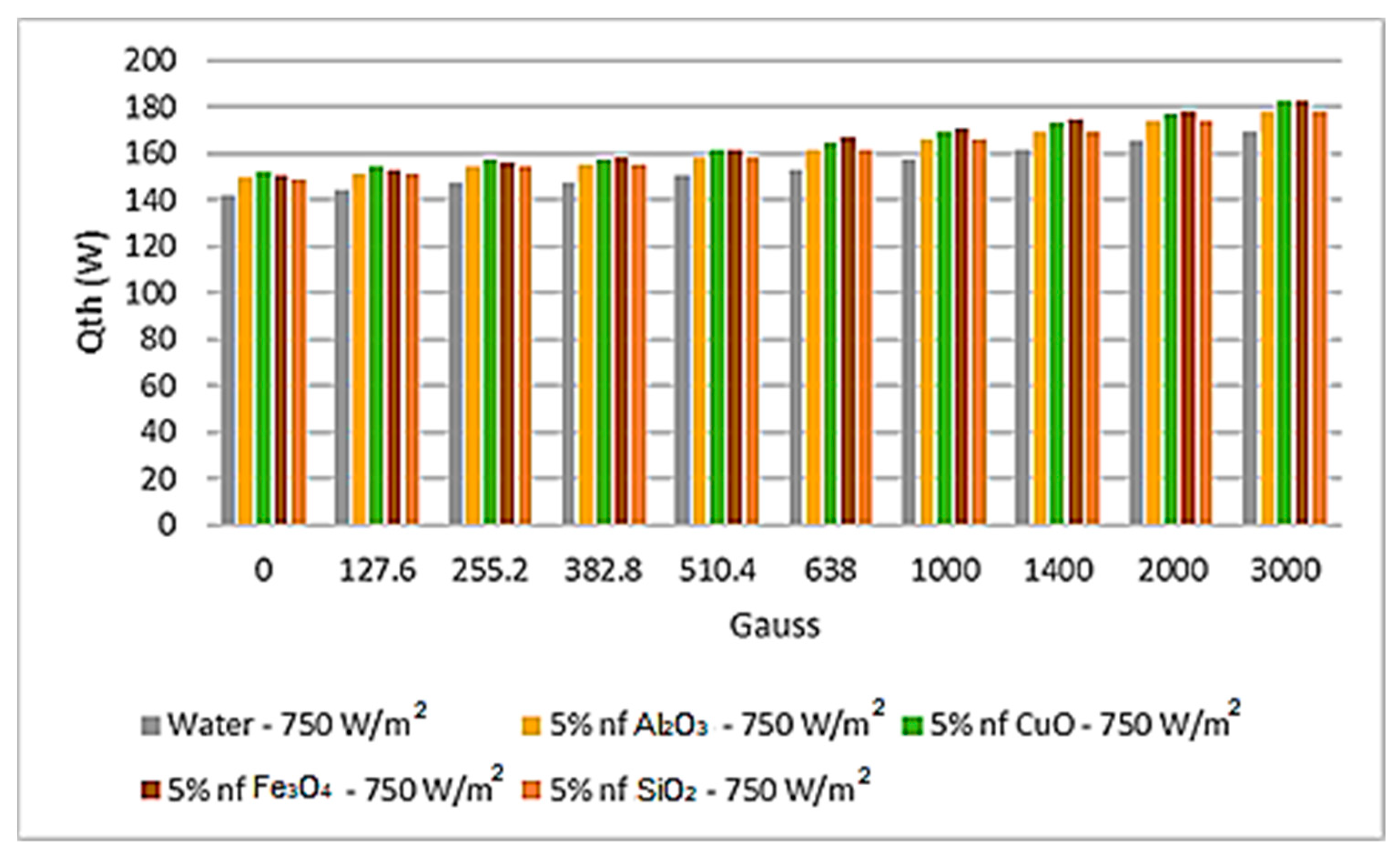
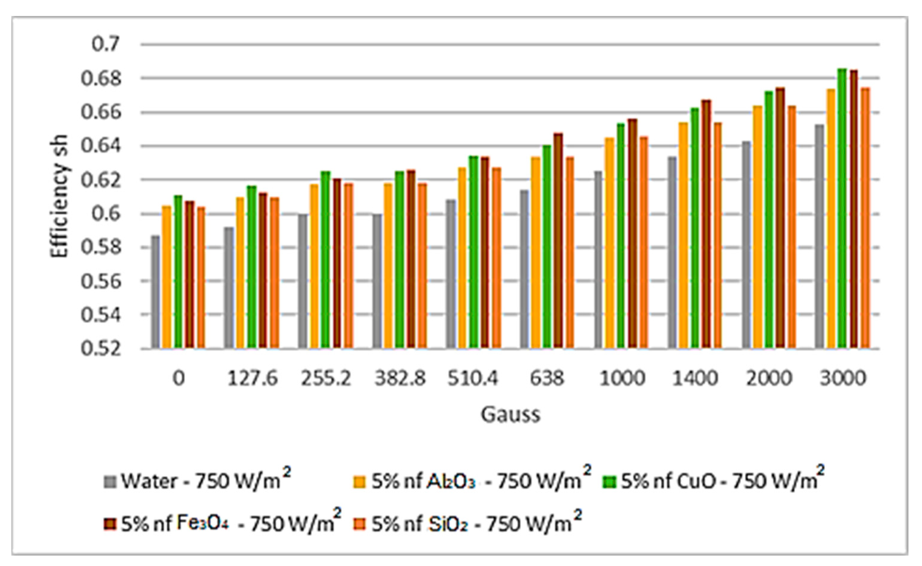
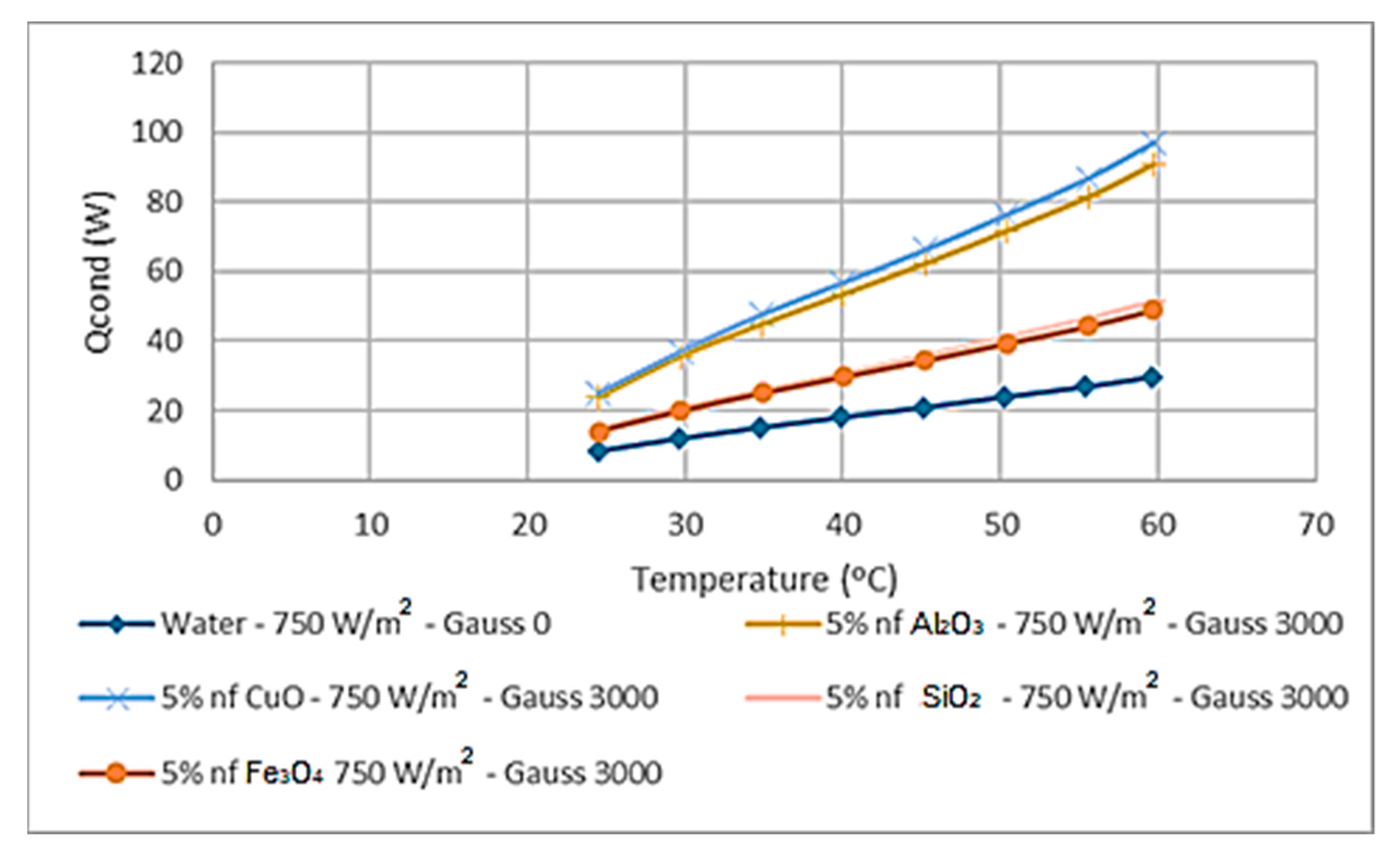
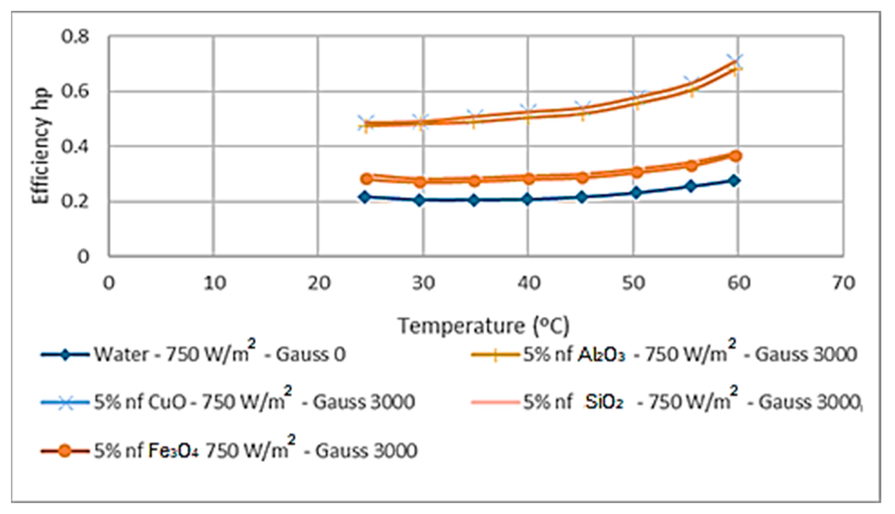
Figure 21,
Figure 22,
Figure 23 and
Figure 24 present a comparison of the key parameters in this study with the different nanofluids under investigation: Al
2O
3, CuO, Fe
3O
4, and SiO
2, at solar radiation 750 w/m
2 and a nanofluid concentration of 5%. It is evident from the results displayed in these figures that CuO nanofluid has the highest absorbed thermal energy dissipated from the PV-Th solar panel compared to the other nanofluids and water as a heat transport fluid, followed by Fe
3O
4 nanofluid. In particular,
Figure 22 demonstrates that better hybrid system efficiency was obtained with CuO nanofluid, followed by Fe
3O
4, compared to the water-based fluid and other nanofluids under investigation. Additionally, it can be noted that the higher the magnetic field, the more thermal energy absorbed and dissipated to the nanofluids, and also the higher the magnetic field, the higher the hybrid system efficiency. As for the characteristics of the heat pipes, it should be pointed out that the use of the Cuo nanofluid resulted in the highest thermal energy dissipation from the heat pipe condenser section into the storage tank. In turn, the highest heat pipe efficiency was obtained with the use of the CuO as a heat transport nanofluid. Additionally, the higher the magnetic field, the more thermal energy developed in the heat pipe condenser section and the higher the heat pipe efficiency.
“The thermal conductivity of a specific material is considered the most dominant characteristic affecting heat transport and is highly dependent on several factors. Thus, the results obtained after this investigation study demonstrated that the CuO nanofluid not only has the highest thermal conductivity but also has higher thermodynamic and thermophysical properties compared to the other nanofluids under investigation, including water as heat transport fluid. It has also been shown by other references [
21,
22,
23,
24,
25,
26,
27,
28,
29,
30,
31] that the heat transfer coefficient of nanofluid becomes higher than that of pure fluid at the same Reynolds number and increases with the increasing of the mass fraction of CuO nanoparticles”.
“It was reported in the literature [
15,
16,
17,
18,
19,
20,
21,
22,
23,
24,
25,
26] that the thermal conductivity of magnetorheological fluid increased with increasing magnetic field in the temperature intervals from 0 to 50 °C and from 50 to 100 °C and the direction of the magnetic field influenced the thermal conductivity. This was supported by very recently reported work [
39] that found that ferrofluid additives caused a tremendous improvement in the heat transfer of the fluid. The use of the alternating magnetic field also led to an increase in the heat transfer rate, along with the spiral coil.” The observations reported in the aforementioned studies are in agreement with others in the literature as long as the increase in the PV cell temperature was within the limitation imposed by the manufacturer. Similar observations have been made with the other nanofluid concentrations of 10% and 20% in this study.


