1. Introduction
Neuromorphic engineering is inspired by the human neural system to address abstraction and automate human-type activities [
1]. Spiking neuronal networks (SNNs) can be implemented in neuromorphic systems and together they are a part of the third generation of artificial intelligence [
2,
3]. The information in SNNs is encoded by the signal itself and its timing, and the signal only typically has two states: logical ‘1′ and logical ‘0′. This encoding works towards reduced computational complexity in comparison to conventional deep neural networks which deal with real values. This type of encoding is also in coherence with address event representation (AER) which is often used in sensory neuromorphic systems [
4].
The inherent sparseness of SNNs make them suitable for event-based image processing. Conventional cameras capture 25 or more still frames per second to present motion. Each frame in this representation is independent and normally the identical background is repeatedly recorded, which increases computational complexity and generates excessive and often useless data. However, pixels in event-driven cameras only generate data when they detect changes that are above a pre-defined threshold. This presentation enables neural networks to process the information it needs, without spending time and power to process irrelevant parts. Each pixel in an event-driven camera, such as dynamic vision sensor (DVS) [
5], is independent; the resulting data are sparse, and information is encoded by the location of events and its timing. These features of event-driven cameras are in line with the characteristics of SNNs. Each neuron in the input population of SNNs can correspond to a pixel of the DVS. Once a pixel generates an event, the corresponding neuron can be injected with a spike. This encoding method makes SNNs an appropriate platform to process event-driven image processing. Compared to conventional deep convolutional networks (CNNs), and the task of video processing, SNNs require much less computational resources, hence lower power consumption and lower reaction latency compared to CNN.
Hardware solutions for neuromorphic computing have been developed to simulate large-scale SNNs in real-time, such as TrueNorth [
6], Neurogrid [
7] and SpiNNaker [
8,
9], and they use asynchronous processing of spike-events. In conventional chip designs, the speed of all computations is set by a global clock. However, SNNs are inherently sparse and calculations are only performed when an event signal is present. Thus, the asynchronous model is more suitable for SNNs computations. Furthermore, neuromorphic chips have a routing network, which applies time-division multiplexing to send data packets. This networks-on-chip design increases the extent of connectivity since the multi-layered two-dimensional connection topologies are mainly used in silicon chip [
8]. Additionally, neuromorphic chips use distributed on-chip memory to reduce the influence of memory bottleneck, and non-volatile technology to implement synaptic strength and plasticity [
9].
The neuromorphic processor used is SpiNNaker [
8], which has one ethernet port to communicate with the host PC and it does not support direct communication with external devices. To solve this, advanced processor technologies (APT) group at University of Manchester (UM) uses a PC to convert communication protocols between SpiNNaker and external devices [
10], which is not suitable for mobile robotics. APT group also designed a field programmable gate array (FPGA) interface to convert the data received from DVS to spikes and then inject these spikes into SpiNNaker [
11]. It is a unidirectional data flow and cannot be applied for closed-loop execution.
Apart from the FPGA interface, UM and Technical University of Munich (TUM) developed a microcontroller interface that supports bidirectional data transmission [
12]. In this solution, an additional complex programmable logic device (CPLD) is used for the converting protocol between SpiNNaker and the microcontroller. The data bus in SpiNNakerLink is 7 bits, and it becomes 9 bits after the conversion of the CPLD [
11]. This solution also has five pre-defined ports for two DVSs and three motors, which simplifies the connection of DVSs and motors, but also results in a limited capacity for other external devices and sensors, such as optical flow sensor. Furthermore, the two chips applied in this solution also mean higher power consumption and increased difficulty for further development.
TUM applies their interface to the robot called ‘PushBot’ or ‘SpOmnibot’, which uses Wi-Fi access point to relay the robot and a host machine [
13,
14]. The Wi-Fi connection increases the mobility of the robot at the expense of higher reaction latency. Another event-driven platform which combines SpiNNaker with a spiking silicon retina (such as ATIS) has been demonstrated on real-time object recognition task, specifically to classify 26 class characters [
15], as well as for object tracking [
16].
In addition to the applications where SpiNNaker was combined with a vision sensor, it has been used in multiple physical autonomous robots, such as musculoskeletal robotic hardware with neural control implemented on SpiNNaker [
17]. Another application area of SNNs run on SpiNNaker is in the context of cognitive robotics, where the goal is identifying the approach and strategy how to compute. It has been demonstrated on a robot called ‘iCub’ and SpiNNaker, which has been developed to grasp the task of object-specific attention [
18].
Neuromorphic systems controlled by SNNs, but implemented on VLSI chips (instead of SpiNNaker), have been also demonstrated, such as an open-loop motor controller [
19], which offer lower power consumption and simplified motor control. For robotic motion tracking using neuromorphic vision sensor, algorithms have been developed to distinguish the background and the moving object, to be used in combination with Hexapod robot [
20] or iCub humanoid robot [
21].
Deep neuronal networks applied in low-latency conventional vision-based robotics require high computational power and are dependent on a powerful, graphics processing unit (GPU)-driven PC. For a camera with say 50 frames per second, the response latency is not less than 20 ms, which is far from enough to support a fast-reacting robot. If the frame rate is increased to 5 kHz, the corresponding data rate will be 234.375 MB/s for a resolution of 128 × 128 pixels. An alternative is to use an AER type camera device [
22]. A robotic goalkeeper based on the DVS128, designed by Delbruck and Lang [
23], achieves 3 ms reaction time. However, this system is using a PC to process data, which is reducing its mobility and power efficiency, and it cannot capture rich non-linear structures of visual input since neuronal networks are not applied in the system.
In order to utilise SNN for motion processing and implement the interface between SpiNNaker and external devices, a neuromorphic robotic platform consisting of a DVS, SpiNNaker and a servo motor has been designed. It is a ready-to-use neuromorphic platform for running any SNN to process motion in real-time, for example in the field of neuroprosthetics such as motor neuroprothetics, which allows people to bypass the spine and directly control the prosthesis, which is vital for patients with spinal cord injury. In order to evaluate the performance of its closed-loop execution and also demonstrate the benefit of using SNN in such applications, the platform is implemented on a robot goalkeeper. A similar problem of trajectory prediction for robotics, which utilises an event-based camera and a neural network trained to predict the ball’s position has been also investigated by Monforte et al. [
24].
In this paper, the architecture of the system and the principle of hardware communication are described and demonstrated. An evaluation based on efficiency and accuracy is also presented and discussed. The interface developed in this paper uses a single microcontroller to establish low-latency communication between DVS, SpiNNaker and a servo motor. It is the first neuromorphic interface based on SpiNNaker that supports a servo to precisely control the position of the robotic arm. It does not require a second chip to convert the communication protocol between microcontroller and SpiNNaker, which reduces power consumption. Furthermore, an Arduino microcontroller is used. It has a number of built-in libraries for external devices, which means more sensors and actuators supported by the Arduino platform can be added easily into the platform. The components that comprise the system are off-the-shelf, and the software implemented only uses the standard libraries. This neuromorphic system offers a platform for many other applications at low-cost and simple for further development.
2. Materials and Methods
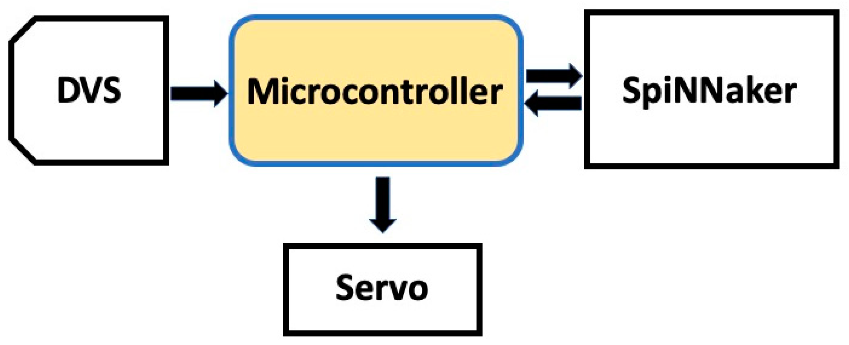
In the designed system, the microcontroller performs communication protocol conversion between DVS, SpiNNaker and the servomotor. The data formats are different for the three components, and are referred to as follows:
Events: visual information captured by DVS and represented by AER protocol (between microcontroller and DVS).
Packets: spikes injected to and received from SpiNNaker (between microcontroller and DVS).
Commands: data used to control the servo (between microcontroller and servo).
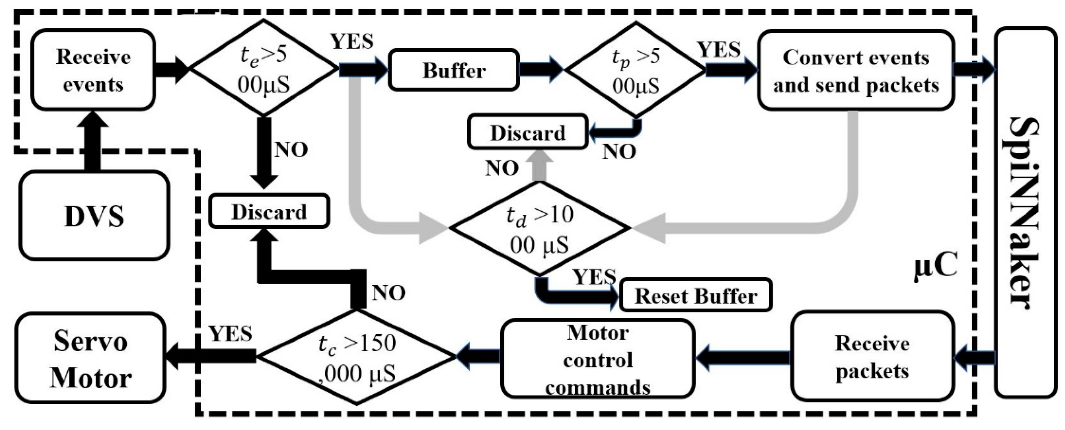
As shown in
Figure 1, the microcontroller receives events from DVS, the events are then converted to packets and injected into SpiNNaker. The microcontroller receives packets (spikes) back from the SNN running on SpiNNaker. Finally, it generates servomotor control commands based on the received spikes.
The neuromorphic processor used is SpiNNaker SpiNN-3 hosted on a development board. It is a multi-chip platform, where each chip has 18 identical processing cores and six bidirectional inter-chip communication links. The SpiNN-3 has 4 SpiNNaker chips and can simulate a SNN with up to 6400 neurons. These chips share a 128 MB SDRAM, which gives over 1 GB/s sustained block transfer rate [
9]. The router can route the spikes from a neuron to many connected neurons. SpiNNaker is designed to optimise the simulations of SNNs, and implements some common neuron models such as leaky integrate and fire model.
The DVS used in our platform is DVS128 from iniLabs, Zurich, which has a resolution of 128 × 128. The DVS camera has low latency down to 15 µs and high dynamic range of up to 120 dB and can work at low power at 20 mW [
5,
22].
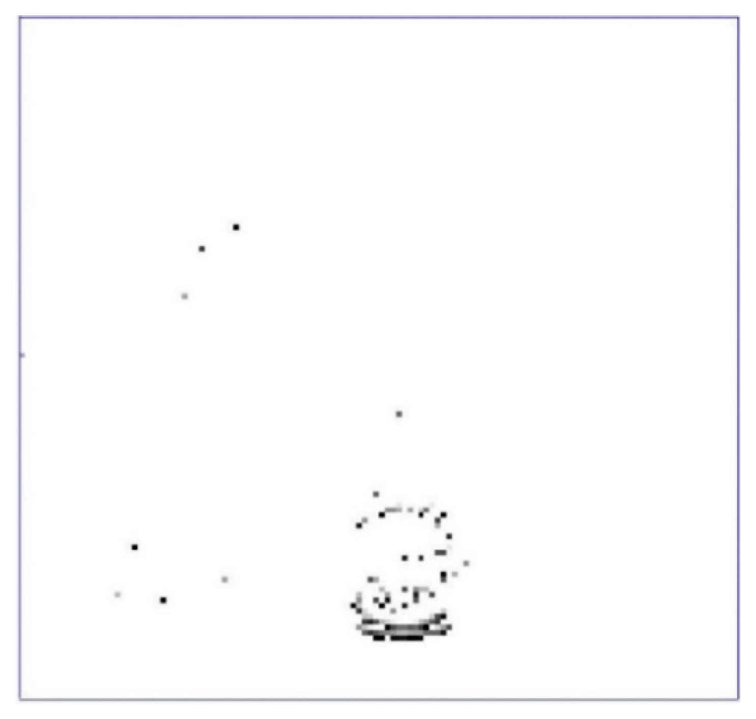
Figure 2 shows a DVS recording when a ping-pong ball is moving. The outline of the ball will produce spikes, but also some random noise is generated, which can be decreased by increasing the threshold of events.
2.1. From DVS to SpiNNaker
DVS only sends the addresses of pixels whose temporal change of intensity is higher than a preset threshold [
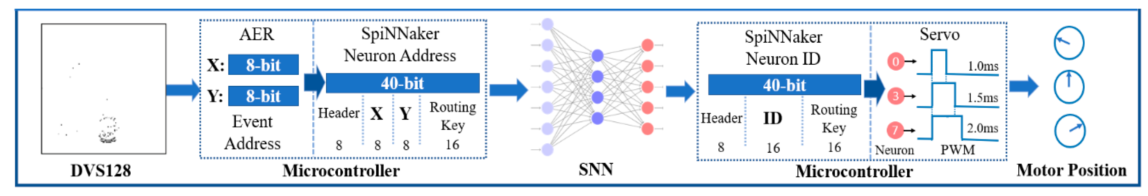
5]. Therefore, the microcontroller receives the horizontal (x) and vertical (y) coordinates of events. The resolution of DVS is 128 × 128, which requires 7 bits to encode the x and y coordinates of the event address. For example, in
Table 1, the packet corresponding to the event at pixel at the position (68,98) is encoded as:
The first bit of header is the parity bit, it is set to ensure the whole packet has odd parity. The rest of header bits and the two unused bits in the packet data are set to 0.
For SpiNNaker, the spikes are encoded as packets, in the following form (
Table 2):
A packet contains: Header to indicate its specification, Packet Data which stores information about the spikes, and an optional PayLoad to carry more information, such as membrane voltage [
8]. The packet format used in the designed system is 40-bit multi-cast packet without payload. Furthermore, SpiNNaker regards external devices as virtual chips on its system [
25]. Thus, a virtual routing key should be defined as the delivery address of the injected spikes. In the designed system, the virtual routing key consists of four Hex numbers (‘0 × 1′, ‘0 × 2′, ‘0 × 3′ and ‘0 × 4′).
The decimal to binary conversion of SpiNNaker packets starts from the least significant bit, and the order of virtual routing key is reversed. The reason is that SpiNNaker reads packets from the end.
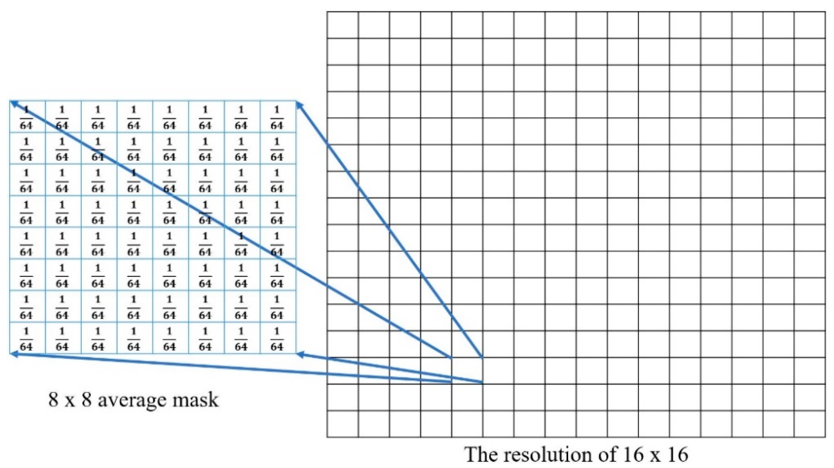
The events received by the microcontroller can be sub-sampled or preprocessed to increase the processing speed and filter random noise. The resolution reduction is also important for reducing the size of the neural network needed to handle the DVS events. As shown in
Figure 3, an average mask of 8 × 8 has been applied to the received events and a new threshold is set to the averaged pixel value to define whether the ‘superpixel’ is generating an event or not.
Through the resolution reduction, only 4 bits are needed to encode x and y of the events, respectively. For instance, the packet corresponding to the event at superpixel (3,15) is shown in
Table 3.
After receiving the raw pixel data from the DVS, the microcontroller is converting them first into superpixel events, and then into 40-bit packets appropriate for the SpiNNaker system. The microcontroller will send the packets into SpiNNaker by using 2-of-7 coding and 2-phase handshaking protocol. Each packet is sent as 10 symbols followed by an ‘end-of-packet’ (EOP) symbol. Except for the EOP symbol, the 10 symbols are selected from 16 Hex values, and each Hex value is 4-bit.
Both SpiNNaker input and output data buses are 7 bits. To send a symbol, the microcontroller only changes the state of two wires and keeps logical levels of the rest five wires unchanged, i.e., uses the 2-of-7 coding method [
26]. In
Table 4, ‘1’ is represented by change of the state on the that line and ‘0’ is represented with no change of the state. In other words, logical-1 is physically represented by a change of the voltage level and not by a specific value for the digital signal. Similarly, logical-0 is represented by no-change of the physical voltage on the wire, not by a specific value. After sending a symbol, the voltage levels of the 7 wires will not return to the initial state [
27]. This mechanism increases the transmission speed and reduces power consumption.
After the microcontroller changed the logical levels of two wires, SpiNNaker will send back an acknowledge (ACK) signal to indicate the symbol (data) has been received. For the microcontroller, it will send the next symbol, once it receives the ACK signal from SpiNNaker. Through this 2-phase handshaking protocol, packets are sent serially.
2.2. From SpiNNaker to Servomotor
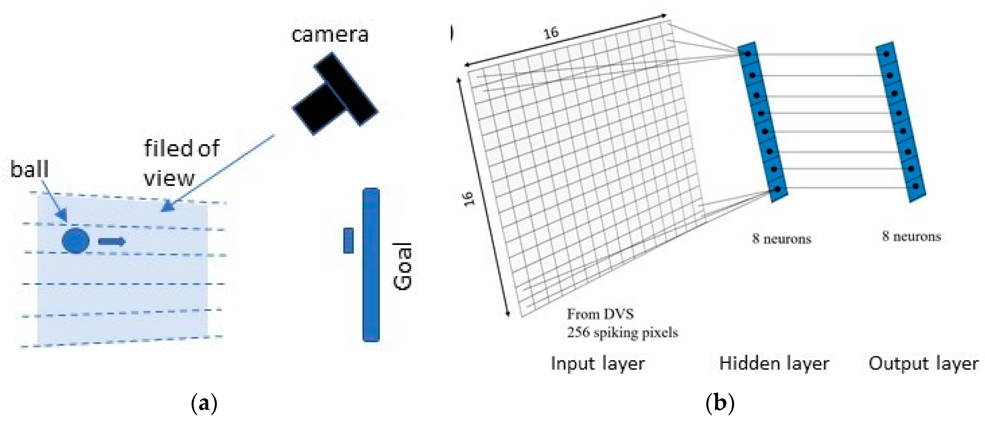
After injecting spikes into SpiNNaker, the next hardware communication is to receive spikes back from SpiNNaker i.e., the output layer of the SNN that it runs, and control the servo on the bases of the received spikes. The coding method and communication protocol is the same as for injecting spikes into the SNN, and the IDs of spiking neurons in output population are also sent in 40-bit packets. In our case, the single-axis robotic arm of the neuromorphic system is set to have eight different movable positions. Thus, the output layer of the SNN has eight neurons that correspond to eight positions. What the microcontroller receive is the spiking neuron ID. It is possible to set any other number of the goalkeeper positions using this digital motor.
The rotation range of the servomotor is 120°, from −60° to 60°. It is divided into eight equal steps, with the step angle of 15°, and each postion corresponds to a neuron ID. The speed of the servomotor is 120°/150 ms = 0.8°/ms (for the weight of our ‘goalkeeper’). Thus, servo commands are executed at most every 150 ms. The position of the robotic arm is precisely controlled by using pulse width modulation (PWM) [
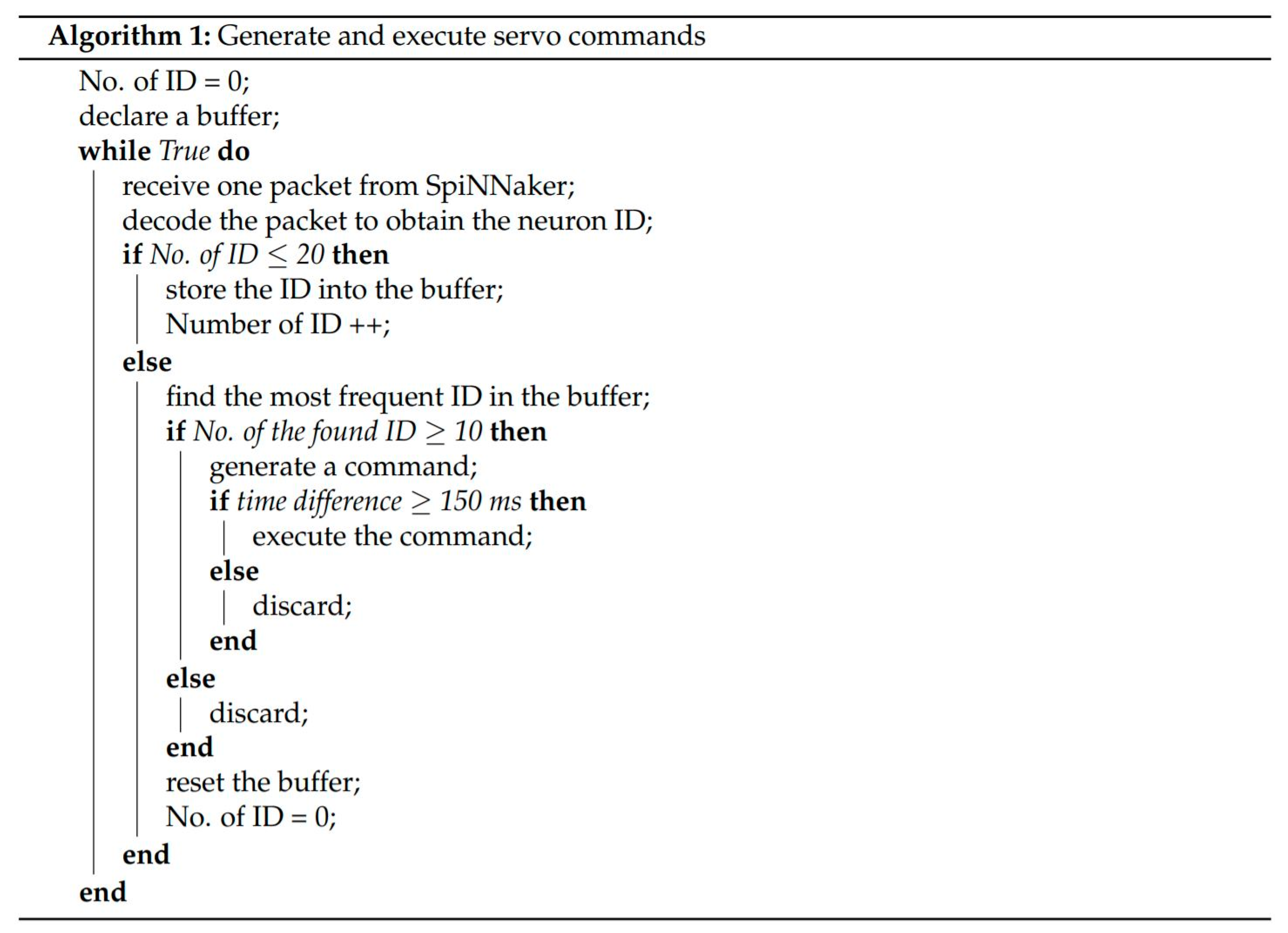
28]. The range of pulse widths is from 1 ms to 2 ms, which is also divided into eight equal parts. The method of controlling the servo is described in the algorithm (
Figure 4) below. The position of the robotic arm is changed after minimum 20 neuron IDs. The microcontroller keeps storing the received neuron IDs into a buffer until the number of IDs is 20. Next, the number of the most frequent ID in the buffer is found. If the number is equal to or greater than 10, a servo command corresponding to the ID will be generated. Finally, the command will be executed if the time difference from the latest execution is equal to or greater than 150 ms.
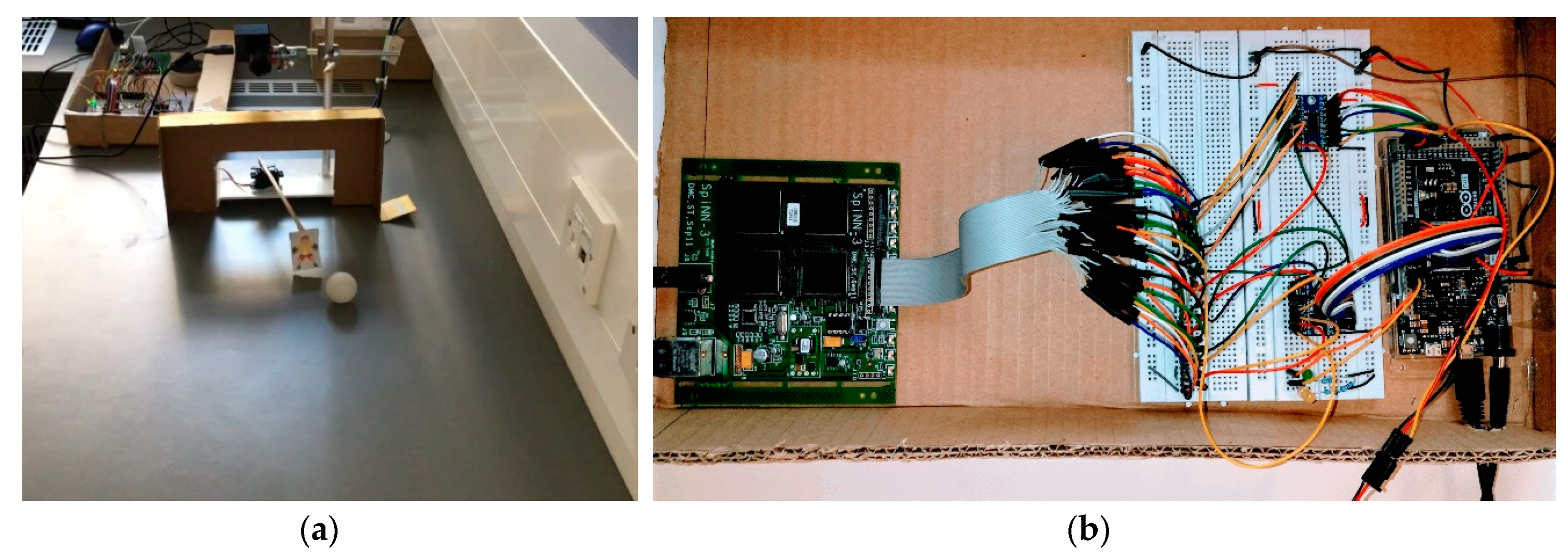
4. Results
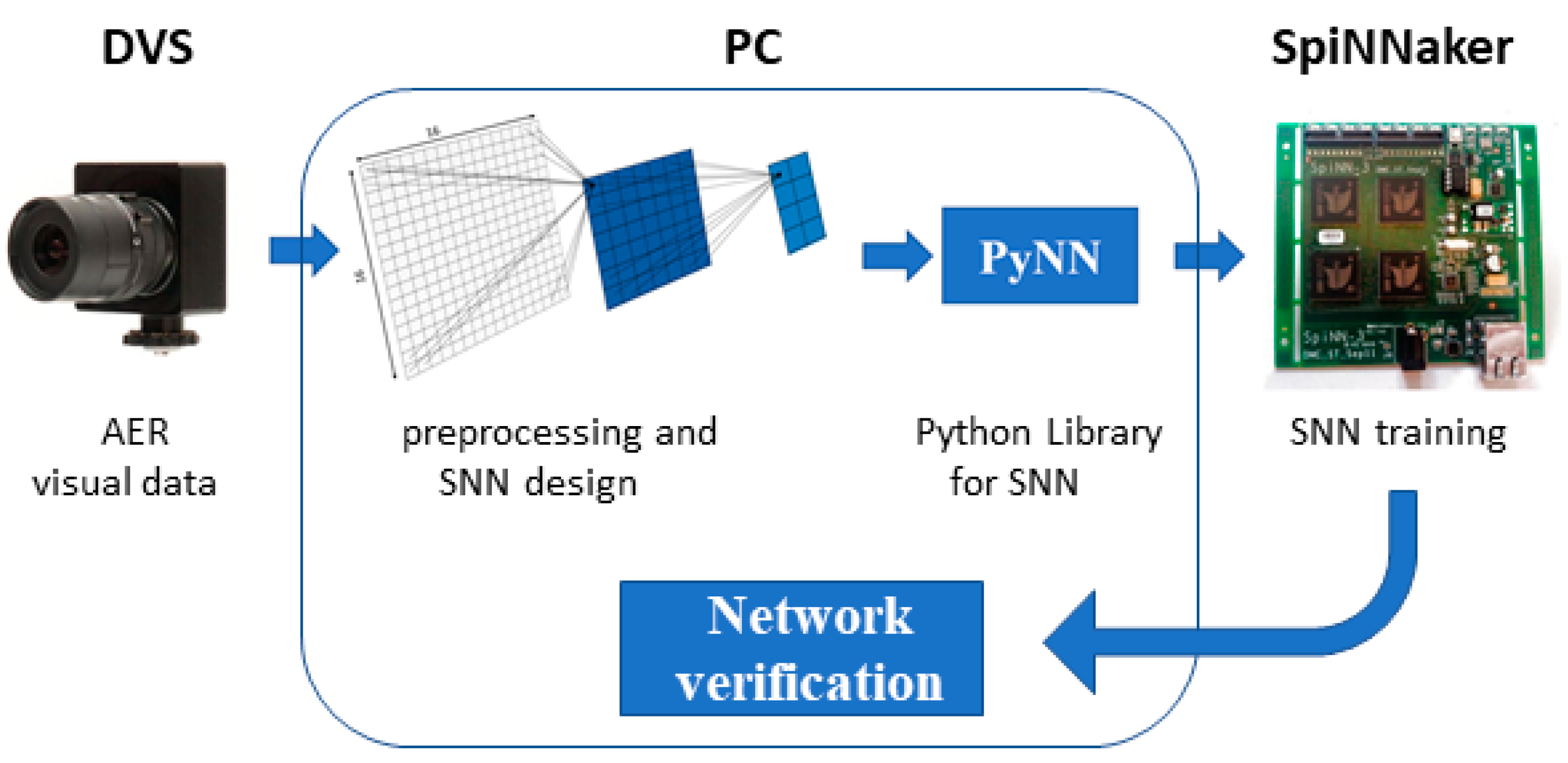
The SNN has been coded in PyNN and downloaded to SpiNNaker. After the network was downloaded, the SpiNNaker board (i.e., the ethernet link) has been disconnected from the laptop, to demonstrate PC-independent operation. Once the simulation starts, the SNN will run for arbitrary time (typically 60 s in our experiments) with a time step of 1 millisecond. The input layer receives the injected spikes from the microcontroller, and the output layer has eight neurons corresponding to the eight positions. The network will not send any packets unless a neuron in the output population is spiking. A demo video of the robot goalie action can be found at the following link:
https://www.youtube.com/watch?v=135fH21QXtg. The neuromorphic goalkeeper achieves an accuracy of up to 85% on the condition that the speed of the ball is up to 1 m/s and the initial distance more than 80 cm.
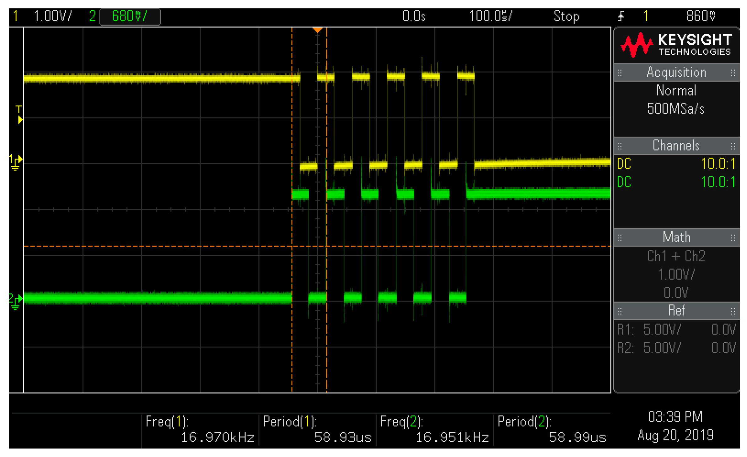
For the hardware communication, the logical levels of the ACK signals of injecting spikes (uplink) and receiving spikes (downlink) are monitored to measure the transmission speed,
Figure 9. As can be observed both ACK signals of uplink and downlink have changed 11 times to send a packet, which indicates that data is in the form of 40-bit packets followed by an EOP symbol.
According to the reading of the oscilloscope, the frequencies of uplink and downlink ACK signals are 16.951 kHz and 16.970 kHz, respectively. Two symbols are sent in one period, since the logical levels of ACK signals change twice every period. Therefore, the uplink speed is:
The microcontroller receives events in parallel but injects and receives spikes in serial. Thus, the speed of receiving events is higher than the speed of injecting and receiving spikes. Since each process are parallelly executed and the speed of injecting spikes is higher than the speed of receiving spikes, the response latency is dominated by the time cost to inject spikes. Furthermore, the servo command is generated based on 20 spikes. Thus, the response latency is:
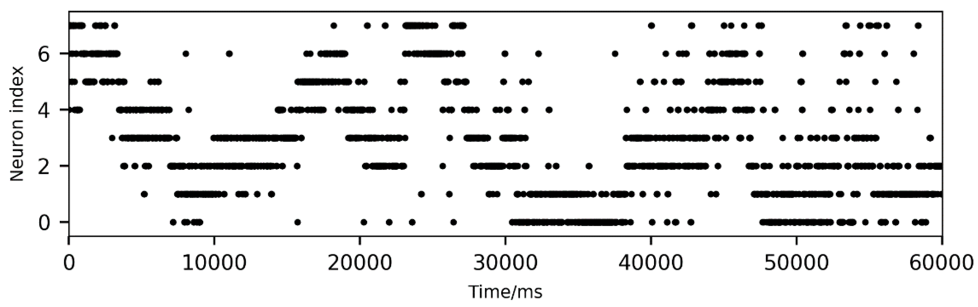
The SNN was running for 1 min in multiple trials, and its output spikes were recorded. Since the servo motor was set to have eight movable positions, the abscissa of the coordinate where the ball can move is also divided equally into eight parts. The microcontroller obtains current coordinate of the moving ball from DVS and inputs it to the SNN. The classification of the coordinate will then be output by the SNN. For example, neuron 6 in the output layer of the SNN will spike if current abscissa of the moving ball is in the 6th position. An example of the SNN activity for some randomly released balls is shown in
Figure 10. The output spikes are concentrated at one or two neuron IDs in a short period, which gives strong and effective guidance for the microcontroller to generate servo commands. Because of the voting method applied in
Figure 4, the effect of random noise has been reduced.
The neuromorphic robotic system has a maximum power consumption of 7.15 W, which is calculated in the following way. For DVS at high activity, its supply voltage is 5 V and the current is 100 mA. For the microcontroller, its operational voltage is 3.3 V and it has a maximum fuse current of 500 mA. For SpiNN-3 board, its power supply is 5 V, idle current is 400 mA and peak current is 1 A [
31]. Therefore, the maximum power of the system is:
In our case the neural network can be run on only one chip (one of four) on SpiNNaker, which requires less than 2 mW of power, so the average power consumption in our example is approximately 4 W.
The developed system has high efficiency due to the inherently sparse events and spikes, impulse propagation of SNNs [
32], and the synchronisation mechanism. The transmission speed of hardware communication is not fixed, it only has an assumed limit for the maximum speed in our realisation, but it could be relaxed. The speed is proportional to the events captured by DVS. Because of the adaptive speed, the efficiency is significantly improved.
5. Discussion
The platform developed in this paper has successfully demonstrated the closed-loop communication between DVS, SpiNNaker and a servo motor by using a single microcontroller. Compared to unidirectional communication of the FPGA interface, the developed solution supports bidirectional data flow and can control external actuators according to the received spikes from SNNs. The FPGA interface is based on a high-cost RoggedStone2 development kit, while our solution is based on the Arduino platform, which is more economical.
Apart from this solution, another microcontroller interface developed by the UM and TUM also supports bidirectional communication and control actuators. However, it requires the assistance of a CPLD, which increases the data transmission speed between SpiNNaker and the microcontroller but also increases the difficulty of further development. Their solution is based on an ARM Cortex-M4 microcontroller with a 168 MHz clock speed, whilst we use a Cortex-M3 microcontroller with an 86 MHz clock speed. Thus, the data transition of our solution is slower than the speed of the interface designed by UM and TUM. On the other side, our solution does not need the second chip, which means lower power consumption and higher stability. Additionally, the microcontroller developed by UM and TUM has 5 pre-defined peripheral ports for 2 DVSs and 3 motors. This design simplifies the connections with DVSs and motors but results in a limited capacity for other actuators and sensors. The microcontroller board used in our solution has 54 GPIOs and built-in libraries for external devices.
Compared to the robot goalie based on a PC (and DVS), the neuromorphic system that uses SpiNNaker as the processor has a lower power consumption, and it is completely controlled by an SNN running on a SpiNNaker, not using any PC processing power. Therefore, our system is portable and readily implementable on autonomous, battery-operated robotic applications. Admittedly for a small neural network as ours it would be possible to implement it on a microcontroller and thus the power consumption could be even lower than by using SpiNNaker. However, SpiNNaker is much easier to be used in developing a new SNN for our platform because of already existing PyNN software interface, and the power consumption is still acceptable for robotic applications.
Our solution can also be compared with other neuromorphic systems for tracking objects by using artificial neural networks. For example, Monforte et al. [
24] have developed a recurrent neural network (RNN) for predicting the trajectory of a bouncing ball (the hardware used was ATIS event camera and iCub robot [
16,
21,
24]). The input events of this neural network were also pre-processed by sub-sampling. This strategy reduces the computational complexity, but can affect the resolution precision. The RNN was using the long-short term memory (LSTM) learning rule [
24], which indicates the current output is depended on previous input events. It is similar to our algorithm where the current prediction of the position of ball’s arrival is based on 20 latest spikes received from SpiNNaker (
Figure 4). Prediction of the upcoming trajectory of a tracked object was done in an asynchronous fashion. The RNN gives both horizontal and vertical prediction, but our algorithm only focuses on horizontal information. The training set and the testing set of the RNN are recorded data, and its performance of real-time events has not been investigated.
The camera (DVS) used to capture the information of moving objects is of the neuromorphic type, which exploits data-driven, event-based updates—the same as SNNs. It generates inherently sparse data, which is important for low latency and energy-efficient applications. Compared to frame-based cameras, bandwidth and computational complexity are greatly reduced. Furthermore, DVS is much better for the task of object tracking since the static background does not generate data.
The motor control mechanism used in the developed system is PWM, and it can precisely place the robotic arm. Compared to the pulse-frequency-modulation (PFM) motor control for neuromorphic robotics [
19], PWM is in the standard library and does not require extra hardware. However, PFM has lower electromagnetic interferences and response latency at the expense of high-cost and complex design.
Although a relatively simple neural network model is used in this work, it is surprisingly efficient, as demonstrated in our YouTube video, as long as the incoming ball’s trajectories are not deliberately chosen to play on the weakness of the model, which is to change the ‘lanes’ of motion. The goalkeeper can only focus on one ball at the time, hence the accuracy will be reduced if more than one moving ball appear in the field of view of DVS simultaneously. However, this constraint is more due to the simplicity of the used SNN rather than being a hardware limitation. For further improvement of the robot for this task, an advanced SNN could be developed, based on, for example, the human ball-catching models.
Another possible limitation of our SNN and potentially use of a DVS in general is the situation when the background is changing. In that case the number of events will increase rapidly what might overload the capacity of the microcontroller to handle them, and also to force all pixels to spike almost simultaneously after post-processing and resolution reduction. Some moderate change of the background including some other small objects moving in the field of view or some noise is currently eliminated by adjusting the spiking threshold in the DVS, as well as with our post-processing of events (decision when a super-pixel spikes) and our algorithm (
Figure 4) which sets a minimum threshold in the number of spikes in the output layer for making the decision about where to move the goalkeeper.


