Abstract
An open-cell metal foam gains a lot of interest from researchers due to its unique porous structure, which provides high surface area and good tortuosity, as well as being lightweight. However, the same structure also induces a massive pressure drop which requires an optimum design to suit applications, for example, a partially filled setup or staggered design. Thus, better attention to the slip velocity at the interface between the porous structure and non-porous region is required to maximize its potential, especially in thermal fluid applications. This study proposed a slip velocity model of an open-cell metal foam by using a reverse engineering method and 3D printing technology. A series of experiments and a dimensionless analysis using the Buckingham-Pi theorem were used to compute the slip velocity model. Results show that the pressure drop increases with decreasing pore size. However, the blockage ratio effects would be more significant on the pressure drop with foams of smaller pore sizes. The proposed slip velocity model for an open-cell metal foam agrees with the experimental data, where the predicted values fall within measurement uncertainty.
1. Introduction
An open-cell metal foam is a porous structure made of a solid matrix and interconnected pores. It is classified as one kind of porous media, which is promising for diverse applications such as thermal management [1], crash or sound absorption [2], and building material [3]. Initially, the open-cell metal foam can be manufactured using conventional methods such as foaming of melts by gas injection and solid-gas eutectic solidification. Later in IR 4.0, with the development of additive manufacturing technologies (3D printing), various objects could be produced faster and easier. Different kinds of material can also be used to produce the object if its STL file (3D printing format file) is made available. Hence, the unique microstructure of the open-cell metal foam can be produced using the same technology [4]. However, its performance in the thermal-fluid application should be well-understood before classifying it as a new generation of open-cell foam. Meanwhile, a closed-cell metal foam has individual enclosures within the material, which also possess excellent characteristics such as optimal strength-to-weight ratio, reduced thermal expansion coefficient, and excellent energy absorption [5,6,7,8]. The closed-cell foam also exhibits lower density [9,10] and good damping properties [10]. As one would expect, the pressure drop effects can be seen as the fluid flow passes through its complicated porous structure [11,12,13]. Thus, a partially filled design has been considered to minimize the effects. In the proposed design, a pipe, duct, or any configuration is partly filled with a porous structure, creating two main regions: (1) free stream and (2) porous regions. A small region in between those two regions is called an interface region. Regardless of the outer geometries, the partially filled design causes the emergence of slip effects at the interface [14]. In a pioneering work, Beavers and Joseph (B-J) [15] introduced the existence of slip velocity at the interface between the metal foam and fluid regions. The study stated that tangential stress causes the fluid to slide closely below the interface area when a viscous fluid passes by a porous structure. Thus, the velocity close to the interface region is called tangential slip velocity, which is slightly higher than the pore velocity. The tangential slip velocity has been discussed in many other studies of various porous media [16,17,18]. Using porous nickel metal foam, B-J [15] established a boundary condition where the fluid slip velocity Us is proportional to the shear rate at z = 0, and introduced a dimensionless quantity that is independent of the height of the clear fluid channel and fluid viscosity [19]. Many other studies have proposed various methods to acknowledge the interface boundary conditions by adapting and extending the B-J theory. However, Ochoa-Tapia-Whitaker [20] considered a stress jump at the interface region. The study used the volume averaging method to categorize different regions on either side of the interface and obtained corresponding governing equations. Similarly, Kuznetsov [21] extended the investigation by Vafai and Kim [22] acknowledged the presence of stress jump at the interface. However, Kuznetsov [23] only performed analytical solutions for a steady, fully developed laminar fluid flow without experiment works. Meanwhile, Chandesris and Jamet [24] introduced a non-uniform phase transition zone at the interface between fluid and porous medium, where the porosities are considered to fluctuate rapidly. The boundary conditions were analysed in the study using the matched asymptotic expansion method. It is concluded that the stress jump condition is related to the pressure gradient, and the characteristics of the transition zone have an important influence on the stress jump coefficient. Vafai and Kim [25] suggested that the velocity and shear at the interface between the free stream and porous media should be treated continuously.
In most research regarding a partially filled setup with a porous medium such as open-cell metal foam, the numerical method [26,27,28] and analytical approach [29] are preferred since the experimental works are tedious, time-consuming processes, and the material is expensive. However, the complex flow phenomenon at the interface of open-cell metal foam-fluid regions could not just be explained using continuity equations. Fluctuated slip velocities at the interface should be expected due to the existence of secondary flow from the porous region into the free stream region, which is influenced by the metal foam height, length, and pore density [30]. Thus, adapting the conventional theory of slip or no-slip conditions at the interface of metal foam fluids is inaccurate. Unfortunately, until recently, there has been very limited experimental study on the slip velocity of open-cell metal foam. There is no exact equation or model to specifically describe its interface condition. However, a basic understanding of this matter is essential to maximize the benefits of pore-ligament construction since the flow is anticipated to filled-in or pass through the entire porous region. Thus, this study proposed a novel technique to predict the slip velocity model of conventional open-cell metal foam by using 3D-printed open-cell foams with various microstructural properties. The foams were produced using a Computed-Tomography (CT) Scan and Selective Laser Sintering (SLS). The original small pore diameters of 5 PPI (pores per inch) open-cell metal foam were upscaled to different sizes to estimate the changes in flow velocity across the free stream region towards the interface region. The proposed model will help to estimate the slip velocity of open-cell metal foam, which is difficult to be measured experimentally because of the limited capacity of current measurement devices in the industries and the complicated morphology of the metal foam itself.
2. Materials and Methods
2.1. Buckingham Pi theorem and Dimensionless Group
Since there are minimal studies on the slip velocity in the partially filled design with open-cell metal foam, a dimensional analysis method can be used to generate nondimensional parameters that may influence the slip velocity at the interface. This study performed dimensional analysis using the Buckingham Pi theorem and conducted regression analysis using Excel software. In terms of geometric dimension, the 3D printed foams have the same structure as the conventional open-cell metal foam since a CT-scan is used in producing the printed foams. Furthermore, the material properties are assumed equal since the kinematic similarity is achievable [31]. In dimensional analysis, the dimensionless groups can be formed after defining the effective independent and dependent parameters. The relationship between the slip velocity and the related parameters of a partially filled channel is shown in Equation (1).
Note that the “Us” in Equation (1) is the slip velocity, “Uinlet” is the air velocity measured at the inlet of the test section, U0 is the air velocity that is initially set up in unloaded wind tunnel, “ρfluid” is the air density, “µfluid” is the dynamic viscosity of air, “hf” is the foam height, “hc” is the channel height, “dl” is the mean ligament diameter, “dp” is the mean pore diameter, “K” is the permeability of the 3D printed foam, “ΔP” is the pressure drop across the foam sample and “Δl” is the foam length. The total number of independent and dependent parameters, n = 11, which is tabulated in Table 1 and the dimensionless groups can be derived into 8 Pi groups from three main dimensions, m = 3, while considering the reduction factor “k = n − m”. Three parameters were selected as the repeating parameters, while the rest were considered prime parameters. The data in Table 1 shows the exponent value of the parameters’ basic unit, as listed in the first row of the table.

Table 1.
Dimensional matrix for independent and dependent parameters.
Below indicates an example of calculation steps to determine the dimensionless groups. The first Pi group is defined in Equation (2), simplifying the understanding of parameters and experimental setup. The letter a, b, and c represent the unknown variables that can be solved through homogeneity analysis between the basic units, M, L, and T, and the proposed Pi group.
Π1 = UsUinletaρfluidbhcc
Then, the selected parameters in relation to the Pi groups in Equation (2) are converted in terms of the main dimensions (M, L, T).
Π1 = (L/T)(L/T)a(M/L−3)b(L)c
A dimensionless number, the homogeneity, is shown in Equation (4). Thus, the powers of the dimensionless matrix (M, L, T) are equated and solved to find the unknown variables.
(M0L0T0) = (L/T)(L/T)a(M/L−3)b(L)c
Finally, the dimensionless group is obtained by deducing Equation (1) and inserting all the unknown variables. The final form of the Pi group is shown in Equation (5). Note that, in the final form of the Pi group, the total dimensional matrix should be equal to zero, appropriate with the dimensionless calling.
Π1 = Us/Uinlet
The dimensionless groups obtained from the dimensionless analysis are listed in Table 2, where π1 is a ratio of slip velocity with the velocity at the inlet of the test section, π2 is a ratio between fixed air velocity (measured in empty channel cases) with the inlet velocity, π3 is the Reynold number based on channel height, π4 is a dimensionless group based on pressure gradient, π5 is a ratio of foam height with channel height or blockage ratio, π6 is the ratio of pore diameter with channel height, π7 is the ratio of ligament diameter with channel height and π8 is a ratio of permeability with channel height squared.

Table 2.
Dimensionless π groups.
2.2. Preparation of 3D Printed Foams
Different pore sizes of 3D printed foam samples were produced by upscaling the 5 PPI open-cell metal foam to 2, 4, and 6 times larger than its original size. This study used three foam heights (30, 60, and 90 mm) to build a partially filled set-up in a rectangular channel. The process of producing the 3D printed foams is started by reconstructing the Computed Tomography (CT)-scan image of 5 PPI open-cell metal foam. This study used AutoCAD 2022 software to reconstruct the CT scan images into the desired dimensions of 3D printed foams, as listed in Table 3.

Table 3.
Physical properties of porous foam.
The foam properties could either be measured or calculated using the existing equation. For example, the pore diameter (dp) and ligament diameter (dl) of the 3D-printed foam can be measured using a vernier caliper. However, there are some irregularities on the ligament surface (due to layering effects from the 3D printing process) and pore shapes, resulting in various pore and ligament diameters up to a specific range for each scale-up size. Thus, the mean sizes of the pore and ligament are presented in Table 3 instead of using individual measurements. Meanwhile, the porosity of 3D printed foam, ε could be determined based on a ratio of Vvoid with Vtotal as listed in Equation (6) [32]. The Vvoid is defined as the volume of empty spaces in the porous structure, calculated by subtracting the volume of porous structure with the total volume.
This study determined the permeability of the 3D printed foam by using the Forchheimer equation as shown in Equation (7) [33].
Equation (7) can be also expressed as Equation (8) [33].
Then, an analysis between the pressure drops per unit (foam) length, ΔP/Δl with velocity, U0 is performed to determine the coefficients, a and b. The analysis yielded a fit with R2 > 99.9% as shown in Figure 1.
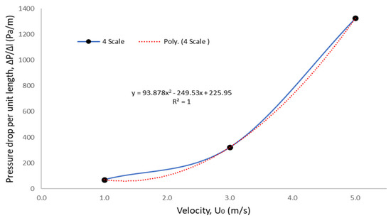
Figure 1.
Example of pressure drops per unit length versus velocity (for the four scale) to determine coefficients.
The permeability and inertial coefficient of the foam are determined by comparing Equations (7) and (8), as shown in Equation (9) [33]. The Forchheimer equation is used to calculate the permeability of a fully filled configuration with 100 mm foam height. Hence, the permeabilities of foams with 30, 60, and 90 mm heights are estimated based on the fractional of a fully filled setup.
In this study, the 3D-printed foams are produced by printing the reconstructed porous structure (STL, 3D image file) using the SLS. In the production process, the nylon powder (FS3300 PA) was sintered and bonded together to create a solid structure, while the unfused powder became the support. A very thin layer of powder was dispersed into a platform, creating a bed of powder, and then, the bed was preheated beneath at the liquefying point [34]. The printing process is done layer-by-layer, where the platform descends to form a new layer of powder on the top once the sintering process using laser for the powder layers is completed [35]. The nylon powder bulk density is 0.48 g/cm3, with a melting point of 183 °C and the same material can be expected to break at 36% of elongation [34]. This study also experimented with conventional open-cell metal foam as a benchmark for those 3D-printed foam samples. Figure 2a–c shows the surface morphology of CAD image, 3D-printed foam, and open-cell metal foam.
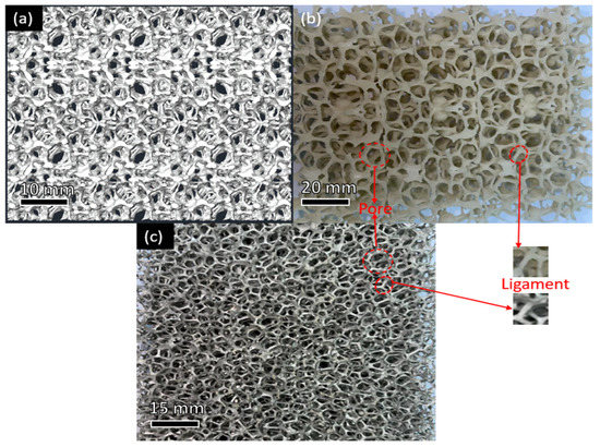
Figure 2.
Porous structure of open-cell foam: (a) CAD image; (b) 3D printed foam; and (c) conventional metal foam.
2.3. Experimental Setup
The pressure drops and fluid flow behaviours were investigated in a small closed-loop wind tunnel, as shown in Figure 3. The test section is made of borosilicate glass and Bakelite, with a size of 100 mm (height) × 100 mm (width). An inverter (TECO Inverter F510) is used to control the air velocity, which is supplied by a high-pressure blower (AIRSPEC, ARC 629, Power = 3.0 kW). A honeycomb structure was installed in the settling chamber of the wind tunnel to produce more uniform air velocity where the fluctuations in the transverse velocity as done by [36].
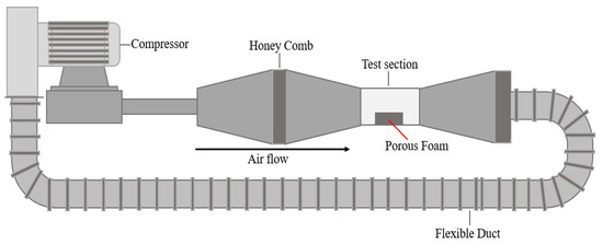
Figure 3.
Schematic diagram of close-loop wind tunnel setup.
A partially filled configuration was set up by placing 3D-printed foam in the middle of the test section, as shown in Figure 4. The porous foam was positioned tightly close to the borosilicate walls. A hot-wire anemometer (HT-9830; Accuracy: 3% + 0.2 m/s) was used to measure the air velocity in the middle part of the test section and at the interface region (see Figure 4). Meanwhile, the pressure drops were measured by placing the pressure taps at the leading and rear edges of the foam with a 10 cm gap. The measurements were taken using a pressure sensor (Sensirion, 500 Pa; Accuracy: ±3%). The installation of foam heights of 30, 60, and 90 mm was considered in conducting slip velocity investigation that enables the occurrence of an interface region (between a free stream and porous regions) for a partially filled configuration in the wind tunnel. Meanwhile, the 3D printed foams with a height of 100 mm are used in producing a fully filled configuration in the wind tunnel to ensure the applicability of Forchheimer’s equation in predicting permeability. At various inlet velocities from 1.0 to 5.0 m/s, ten foam samples with different pore sizes and heights were tested in the middle of the wind tunnel test section. The effects of flow behaviour in the free stream region and the pressure drops were examined.
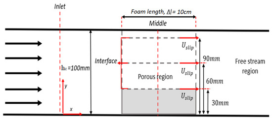
Figure 4.
Schematic diagram of the wind tunnel test section.
3. Results and Discussion
3.1. Pressure Drop Effect
The effects of pore size and foam height on the pressure drops at different measurement points are shown in Figure 5. The data is tabulated in terms of pressure drop per unit length, ∆P/∆l, on the y-axis while the inlet velocity, Uinlet on the x-axis. The fluid flow in the partially filled channel configuration has been restrained by the presence of a porous structure at the middle part of the test section, affecting pressure drop values. The pressure drop for each foam sample shows a similar trend inside the partially filled configuration cases, where the pressure drops increase with the inlet velocity. Each point measurement shows a similar pattern, with 2-scale foam showing a more significant pressure drop than the other scales since it provides more ligament restrictions in the test section. The ligament structure drove away the flow into the free stream area, reducing the total resistance effects of the porous structure. A past study [37] used the Brinkman-extended Darcy model to characterize the pressure drops performances of metal foam had the same trend as found in this study. The pressure drops increase as the pore size decreases. The comparison of pressure drops between 3D printed foams with 10 and 20 PPI open-cell metal foam is shown in Figure 6. The pressure drop also shows a similar trend for both samples, where the pressure drops increase with the inlet velocity and blockage ratio. However, the 3D-printed foam illustrated a higher pressure drop than open-cell metal foam. The blockage ratio of a porous sample shows a positively strong influence on the pressure drop inside the wind tunnel. Therefore, the open cell metal foam with 20 PPI of pore size shows an appealing finding as the pressure drop tends almost in line with the 3D-printed foam with an upscaling pore the sizes of 4 and 6.
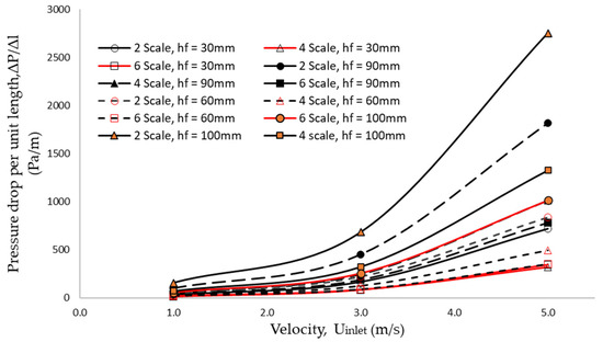
Figure 5.
Comparison of 3D printed foams’ pressure drops with different pore size and foam height.
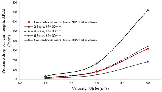
Figure 6.
Comparison of pressure drops between 3D printed foam and conventional open-cell metal foam.
Figure 7 shows that the pressure drops are significantly influenced by the blockage ratio. The fully filled setup (of 100 mm) has the highest pressure drop as compared to the rest, and the partially filled configuration. The pressure drop results are also compared to a cylindrical 3D-printed porous foam [38]. Even though the 3D-printed foam from Bracconi et al. [38] was set up as a fully filled configuration, their pressure drop with a smaller pore diameter of 5 mm is still lower than the 2-scale foam in the partially filled channel. However, their experiment was conducted at a very low Reynold number regime, Re < 50, meanwhile, the 2-scale foam was tested at a higher Reynolds number, larger than 5.86 × 10³. It shows that the flow regime plays a more important role than pore diameter on the pressure drop performance, where the effects of inertia would be prominent at a higher flow velocity.
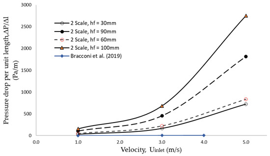
Figure 7.
Comparison of pressure drops between 3D printed foam and existing studies [38].
3.2. Inertial Coefficient
In this study, the inertial coefficient, f was determined by comparing Forchheimer‘s quadratic polynomial equation with the experimental pressure drop gradient, ΔP/Δl. The inertial coefficient measures the drag experienced by the fluid that passes through the porous structure flow and is expected to depend significantly on the pore diameter and foam height. The ratio of pore diameter and foam height is selected as a dependent variable for the inertial coefficient instead of the porosity, as the pore diameter is more affiliated with this study’s foam characteristic. Furthermore, this study used a few different sample heights in conjunction with the pore sizes. Figure 8 shows that the inertial coefficient is inversely proportional to the pore diameter and foam height ratio. The lowest inertial coefficient, 4.86 × 10⁻³ recorded at the highest ratio of pore diameter and foam height, 0.77.
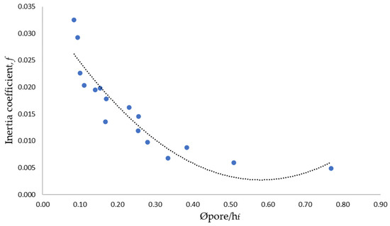
Figure 8.
Inertial coefficient plot against pore diameter per foam height.
3.3. Fluid Behavior and Velocity Profile in Close Loop Wind Tunnel
The study constructed velocity profiles for various blockage ratios with different foam scale sizes, from 2 to 6, as shown in Figure 9. The V1, V3, and V5 indicate the inlet velocities in the tested wind tunnel, which are 1.0 m/s, 3.0 m/s, and 5.0 m/s, respectively. The velocity data collected at 0.5 mm from the interface was assumed as the slip velocity. The rest of the velocities were also measured up to the top wall of the test section. Figure 9 shows that the foam heights and inlet velocities affected the velocity profiles. Fewer data can be found in the free stream region with the thickest foam. At a foam height of 30 mm and inlet velocity of 1.0 m/s, the lowest velocity at the interface region is for 2-scale foam compared to the 4 and 6-scale foams. However, the value increases with thicker foams of 60 mm and 90 mm. Interestingly, the inlet velocity of 3.0 m/s shows the lowest velocity data at the interface compared to the other two, 1.0 and 5.0 m/s, regardless of the foam heights. Thus, it shows that the capability of the fluid to flow inside the porous structure is influenced by the size of the pore diameter and the incoming flow momentum to face the porous structure. The highest velocity can be found at the centre of the free stream region, with a foam height of 30 mm. However, with the thicker foams, the highest velocity was found at the interface region, and the velocity started to become zero, as one would expect, due to a no-slip condition on the top wall of the test section.
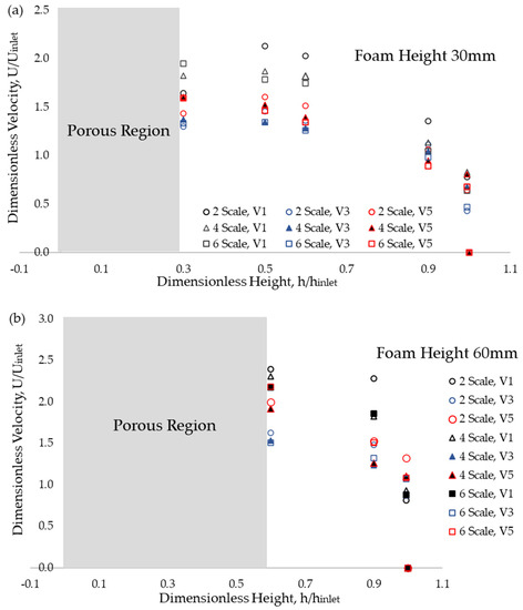
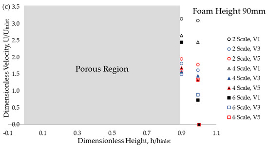
Figure 9.
Velocity profile of 3D printed foam with different pore sizes at foam height:(a) 30, (b) 60, and (c) 90 mm.
3.4. Correlation of Slip Velocity for Partially Filled Channel
A correlation of slip velocity for a partially filled configuration with porous foam is proposed by applying a regression analysis with the possible dimensionless groups obtained from dimensional analysis. The key parameters considered in the dimensional analysis are slip velocity, inlet velocity, the measured velocity at the free stream region, test section height, foam height, pore diameter, ligament diameter, permeability, fluid density, fluid dynamic viscosity, and pressure. The analyses were conducted using a trial-and-error method with larger pore diameters due to the unfeasibility of producing smaller pore sizes through 3D printing. The best conformity of the slip velocity model from the regression analysis was presented in Equation (10). In the regression analyses, with the confidence interval setup at 95%, the p-value is less than 0.05, and the adjusted R2 = 0.88. Thus, the proposed slip velocity model statistically correlates with the experimental data as been demonstrated in Figure 10. The slip velocity model for a partially filled channel with open-cell metal foam is expressed as follows:
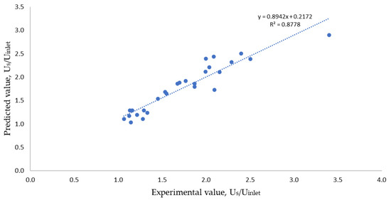
Figure 10.
Experimental versus predicted slip Us/Uinlet of 3D printed foam.
The proposed slip velocity obtained from 3D-printed foams was used to determine the slip velocity of the conventional open-cell metal foam. The result is shown in Figure 11, which represents the slip velocity and inlet velocity ratio versus the dimensionless foam characteristics length, a ratio of pore diameter and foam height. The predicted slip velocity of the conventional metal foam is slightly lower than the experiments but falls within the measurement of uncertainty. For further comparison, other studies that related to the slip velocity and interface condition are also presented in Figure 11. A study by Nair and Sameen [17] used two different porosities; 0.88 and 0.65 at a free stream velocity of 5.1 m/s and 3.88 m/s, respectively. It shows that both data are below the predicted model of conventional metal foam.
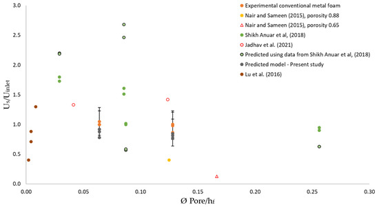
Figure 11.
Comparison of nomenclature of slip velocity versus pore diameter between experimental data, predicted model, and existing literature [17,37,39,40].
An experimental study with a partially filled channel with conventional open-cell metal foam of 10 and 30 PPI [39] scattered accordingly to the key parameter, pore diameter per foam height and the predicted Us/Uinlet using the proposed models show over-predicted and under-predicted values compared to their experimental data. Even though the exact causes are still unknown, it is expected due to high slip velocity at the interface from the presence of secondary flow in their studies. The slip velocity in the present study is also compared with a numerical study from Jadhav et al. [40] with 10 and 45 PPI foam and analytical studies from Lu et al. [37] with 5, 10, and 20 PPI. Both numerical and analytical studies data set falls slightly higher than experimental conventional metal foam in this study, 5 PPI. The results are acceptable since a higher slip velocity is expected to be found with smaller pore diameters as found in Figure 9, especially with significant foam heights.
4. Conclusions
This study presented a slip velocity model for open-cell metal foam in a partially filled channel using 3D-printed foams produced using SLS. The model is built from a dimensional analysis based on key parameters, for instance, ligament diameter, pore diameter, inlet velocity, foam height, etc., to generate a dimensionless Pi group. The pressure drops across the partially filled channel were also considered to describe the inertia effects of the complicated porous foam. The highest-pressure drop in the partially filled channel was induced by 2-scale, 3D-printed foam with a height of 90 mm. Its foam structure with more ligaments provides a higher flow resistance as compared to the other cases. The slip velocity model was formulated using a regression analysis with the computed value of adjusted R2 = 0.86 and p-value < 0.05. The study found that the predicted and experimental value of the slip velocity at the interface of open-cell metal foam is in agreement since the predicted value falls within the measurement uncertainties. The proposed model can determine the slip velocity of a partially filled channel with open-cell metal foam with a pore diameter equal to and smaller than 5 PPI (5.77 mm).
Author Contributions
Conceptualization, K.A.M., F.S.A. and F.A.-Z.M.S.; methodology, K.A.M., F.S.A. and F.A.-Z.M.S.; validation, F.S.A. and F.A.-Z.M.S.; formal analysis, K.A.M. and F.S.A.; investigation, K.A.M.; resources, F.S.A. and F.A.-Z.M.S.; data curation, K.A.M.; writing—original draft preparation, K.A.M.; writing—review and editing, F.S.A. and F.A.-Z.M.S.; visualization, F.S.A.; supervision, F.S.A. and F.A.-Z.M.S.; project administration, F.S.A. and F.A.-Z.M.S.; funding acquisition, F.S.A. and F.A.-Z.M.S. All authors have read and agreed to the published version of the manuscript.
Funding
This research is funded by a KPT research grant under FRGS/1/2020/TK0/UTEM/03/2.
Institutional Review Board Statement
Not applicable.
Informed Consent Statement
Not applicable.
Data Availability Statement
Not applicable.
Acknowledgments
The authors acknowledge the use of facilities within the Universiti Teknikal Malaysia Melaka (UTeM).
Conflicts of Interest
The authors declare no conflict of interest.
Abbreviations
The following abbreviations are used in this manuscript:
| CAD | Computed Aided Design |
| SLS | Selective Laser Sintering |
| CT | Computed Tomography |
| PPI | Pore Per Inches |
| Us | Slip velocity |
| Uinlet | Inlet velocity |
| U0 | Original velocity in unloaded wind tunnel |
| hf | Foam height |
| dl | Ligament diameter |
| dp | Pore diameter |
| hc | Channel/test section height |
| K | Permeability |
| ε | Porosity |
| ΔP/Δl | Pressure drops per unit length |
| µfluid | Fluid viscosity |
| ρfluid | Fluid density |
| Vvoid | Void volume |
| Vtotal | Total volume (full solid) |
| f | Inertial coefficient |
References
- Rabbani, P.; Hamzehpour, A.; Ashjaee, M.; Naja, M.; Houshfar, E. Experimental investigation on heat transfer of MgO nano fluid in tubes partially filled with metal foam. Powder Technol. 2019, 354, 734–742. [Google Scholar] [CrossRef]
- Liang, L.; Wu, X.; Ma, N.; Du, J.; Liu, M. The sound absorption properties comparison of metal foams and flexible cellular materials. Mater. Sci. Forum 2018, 933, 357–366. [Google Scholar] [CrossRef]
- Bedarf, P.; Dutto, A.; Zanini, M.; Dillenburger, B. Foam 3D printing for construction: A review of applications, materials, and processes. Autom. Constr. 2021, 130, 103861. [Google Scholar] [CrossRef]
- Mustapha, K.A.; Shikh Anuar, F.; Mohd Sa’at, F.A.Z.; Zini, N.H.M.; Mat Tokit, E.; Satishwara Rao, N.; Hooman, K.; Abdi, I.A. Production of Open-Cell Foam Using Additive Manufacturing Method and Porous Morphology Effects. In International Conference and Exhibition on Sustainable Energy and Advanced Materials; Abdollah, M.F., Amiruddin, H., Eds.; Springer: Singapore, 2022; pp. 13–16. [Google Scholar]
- Linul, E.; Khezrzadeh, O. Axial crashworthiness performance of foam-based composite structures under extreme temperature conditions. Compos. Struct. 2021, 271, 114156. [Google Scholar] [CrossRef]
- Thomas, K.; Kannan, S.; Nazzal, M.; Pervaiz, S.; Karthikeyan, R. A Numerical Simulation of Machining 6061 Syntactic Foams Reinforced with Hollow Al2O3 Shells. Metals 2022, 12, 596. [Google Scholar] [CrossRef]
- Linul, E.; Pietras, D.; Sadowski, T.; Marşavina, L.; Rajak, D.K.; Kovacik, J. Crashworthiness performance of lightweight Composite Metallic Foams at high temperatures. Compos. Part A Appl. Sci. Manuf. 2021, 149, 106516. [Google Scholar] [CrossRef]
- Movahedi, N.; Linul, E. Radial crushing response of ex-situ foam-filled tubes at elevated temperatures. Compos. Struct. 2021, 277, 114634. [Google Scholar] [CrossRef]
- Szlancsik, A.; Norbert Orbulov, I. Compressive properties of metal matrix syntactic foams in uni- and triaxial compression. Mater. Sci. Eng. A 2021, 827, 142081. [Google Scholar] [CrossRef]
- Dileep, B.; Prakash, R.; Bharath, H.S.; Jeyaraj, P.; Doddamani, M. Dynamic behavior of concurrently printed functionally graded closed cell foams. Compos. Struct. 2021, 275, 114449. [Google Scholar] [CrossRef]
- Ahmed, H.E.; Fadhil, O.T.; Salih, W.A. Heat transfer and fl uid fl ow characteristics of tubular channel partially filled with grooved metal foams. Int. Commun. Heat Mass Transf. 2019, 108, 104336. [Google Scholar] [CrossRef]
- Orihuela, M.P.; Shikh Anuar, F.; Ashtiani Abdi, I.; Odabaee, M.; Hooman, K. Thermohydraulics of a metal foam-filled annulus. Int. J. Heat Mass Transf. 2018, 117, 95–106. [Google Scholar] [CrossRef]
- Alvandifar, N.; Amani, E. International Journal of Heat and Mass Transfer Partially metal foam wrapped tube bundle as a novel generation of air cooled heat exchangers. Int. J. Heat Mass Transf. 2018, 118, 171–181. [Google Scholar] [CrossRef]
- Farooq, J.; Chung, J.D.; Mushtaq, M.; Lu, D.; Ramazan, M.; Farooq, U. Influence of slip velocity on the flow of viscous fluid through a porous medium in a permeable tube with a variable bulk flow rate. Results Phys. 2018, 11, 861–868. [Google Scholar] [CrossRef]
- Beavers, G.S.; Joseph, D.D. Boundary conditions at a natural permeable wall. J. Fluid Mech. 1967, 30, 197–207. [Google Scholar] [CrossRef]
- Nield, D.A. The beavers—Joseph boundary condition and related matters: A historical and critical note. Transp. Porous Media 2009, 78, 537–540. [Google Scholar] [CrossRef]
- Nair, K.A.; Sameen, A. Experimental Study of Slip Flow at the Fluid-porous Interface in a Boundary Layer Flow. Procedia IUTAM 2015, 15, 293–299. [Google Scholar] [CrossRef]
- Guo, C.; Li, Y.; Nian, X.; Xu, M.; Liu, H.; Wang, Y. Experimental study on the slip velocity of turbulent flow over and within porous media. Phys. Fluids 2020, 32, 015111. [Google Scholar] [CrossRef]
- McKay, G. The Beavers and Joseph Condition for Velocity Slip at the Surface of a Porous Medium. Contin. Mech. Appl. Geophys. Environ. 2001, 126–139. [Google Scholar] [CrossRef]
- Ochoa-tapia, J.A.; Whitakeri, S. Momentum transfer at the boundary between a porous medium and a homogeneous fluid I. Theoretical development. Int. J. Heat Mass Transfer 1995, 38, 2635–2646. [Google Scholar] [CrossRef]
- Kuznetsov, A.V. Influence of the stress jump condition at the porous-medium/clear-fluid interface on a flow at a porous wall. Int. Commun. Heat Mass Transf. 1997, 24, 401–410. [Google Scholar] [CrossRef]
- Vafai, K.; Kim, S.J. Fluid mechanics of the interface region between a porous medium and a fluid layer-an exact solution. Int. J. Heat Fluid Flow 1990, 11, 254–256. [Google Scholar] [CrossRef]
- Kuznetsov, A.V. Analytical investigation of the fluid flow in the interface region between a porous medium and a clear fluid in channels partially filled with a porous medium. Flow, Turbul. Combust. 1996, 56, 53–67. [Google Scholar] [CrossRef]
- Chandesris, M.; Jamet, D. Boundary conditions at a planar fluid-porous interface for a Poiseuille flow. Int. J. Heat Mass Transf. 2006, 49, 2137–2150. [Google Scholar] [CrossRef]
- Vafai, K.; Kim, S.J. Forced Convection in a Channel Filled With a Porous Medium: An Exact Solution. J. Heat Transf. 1989, 111, 1103–1106. [Google Scholar] [CrossRef]
- Xu, Z.G.; Gong, Q. Numerical investigation on forced convection of tubes partially filled with composite metal foams under local thermal non-equilibrium condition. Int. J. Therm. Sci. 2018, 133, 1–12. [Google Scholar] [CrossRef]
- Kotresha, B.; Gnanasekaran, N. Numerical Simulations of Fluid Flow and Heat Transfer through Aluminum and Copper Metal Foam Heat Exchanger–A Comparative Study. Heat Transf. Eng. 2020, 41, 637–649. [Google Scholar] [CrossRef]
- Yerramalle, V.; Premachandran, B.; Talukdar, P. Numerical investigation of the performance of interface conditions for fluid flow through a partially filled porous channel. Therm. Sci. Eng. Prog. 2020, 20, 100628. [Google Scholar] [CrossRef]
- Xu, H.; Zhao, C.; Vafai, K. Analysis of double slip model for a partially filled porous microchannel—An exact solution. Eur. J. Mech. B/Fluids 2018, 68, 1–9. [Google Scholar] [CrossRef]
- Shikh Anuar, F.; Ashtiani Abdi, I.; Hooman, K. Flow visualization study of partially filled channel with aluminium foam block. Int. J. Heat Mass Transf. 2018, 127, 1197–1211. [Google Scholar] [CrossRef]
- Hajiahmadi, S.; Elyasi, M.; Shakeri, M. Investigation of a new methodology for the prediction of drawing force in deep drawing process with respect to dimensionless analysis. Int. J. Mech. Mater. Eng. 2019, 14, 1–13. [Google Scholar] [CrossRef]
- Alomair, M.; Tasnim, S.H. Experimental measurements of permeability of open foam. In Proceedings of the 5th International Conference of Fluid Flow, Heat and Mass Transfer (FFHMT’18), Niagara Falls, ON, Canada, 7–9 June 2018; p. 186. [Google Scholar] [CrossRef]
- Bhattacharya, A.; Calmidi, V.V.; Mahajan, R.L. Thermophysical properties of high porosity metal foams. Int. J. Heat Mass Transf. 2002, 45, 1017–1031. [Google Scholar] [CrossRef]
- Walker, D.C.; Caley, W.F.; Brochu, M. Selective laser sintering of composite copper-tin powders. J. Mater. Res. 2014, 29, 1997–2005. [Google Scholar] [CrossRef]
- Herdering, A.; Abendroth, M.; Gehre, P.; Hubálková, J.; Aneziris, C.G. Additive manufactured polyamide foams with periodic grid as templates for the production of functional coated carbon-bonded alumina foam filters. Ceram. Int. 2019, 45, 153–159. [Google Scholar] [CrossRef]
- Mauro, S.; Brusca, S.; Lanzafame, R.; Famoso, F.; Galvagno, A.; Messina, M. Small-Scale Open-Circuit Wind Tunnel: Design Criteria, Construction and Calibration. Int. J. Appl. Eng. Res. 2017, 12, 13649–13662. [Google Scholar]
- Lu, W.; Zhang, T.; Yang, M. International Journal of Heat and Mass Transfer Analytical solution of forced convective heat transfer in parallel-plate channel partially filled with metallic foams. Int. J. Heat Mass Transf. 2016, 100, 718–727. [Google Scholar] [CrossRef]
- Bracconi, M.; Ambrosettia, M.; Okaforc, O.; Sansc, V.; Zhangd, X.; Oub, X.; Fonteb, C.P.D.; Fanb, X.; Maestria, M.; Groppia, G.; et al. Investigation of pressure drop in 3D replicated open-cell foams: Coupling CFD with experimental data on additively manufactured foams. Chem. Eng. J. 2019, 377, 120123. [Google Scholar] [CrossRef]
- Shikh Anuar, F.; Ashtiani Abdi, I.; Odabaee, M.; Hooman, K. Experimental study of fluid flow behaviour and pressure drop in channels partially filled with metal foams. Exp. Therm. Fluid Sci. 2018, 99, 117–128. [Google Scholar] [CrossRef]
- Jadhav, P.H.; Gnanasekaran, N.; Perumal, D.A.; Mobedi, M. Performance evaluation of partially filled high porosity metal foam configurations in a pipe. Appl. Therm. Eng. 2021, 194, 117081. [Google Scholar] [CrossRef]
Publisher’s Note: MDPI stays neutral with regard to jurisdictional claims in published maps and institutional affiliations. |
© 2022 by the authors. Licensee MDPI, Basel, Switzerland. This article is an open access article distributed under the terms and conditions of the Creative Commons Attribution (CC BY) license (https://creativecommons.org/licenses/by/4.0/).