1. Introduction
It is well known that one of the most effective methods for studying the behavior of concentrated bound dispersed systems, such as porous layers or membranes, is the cell method [
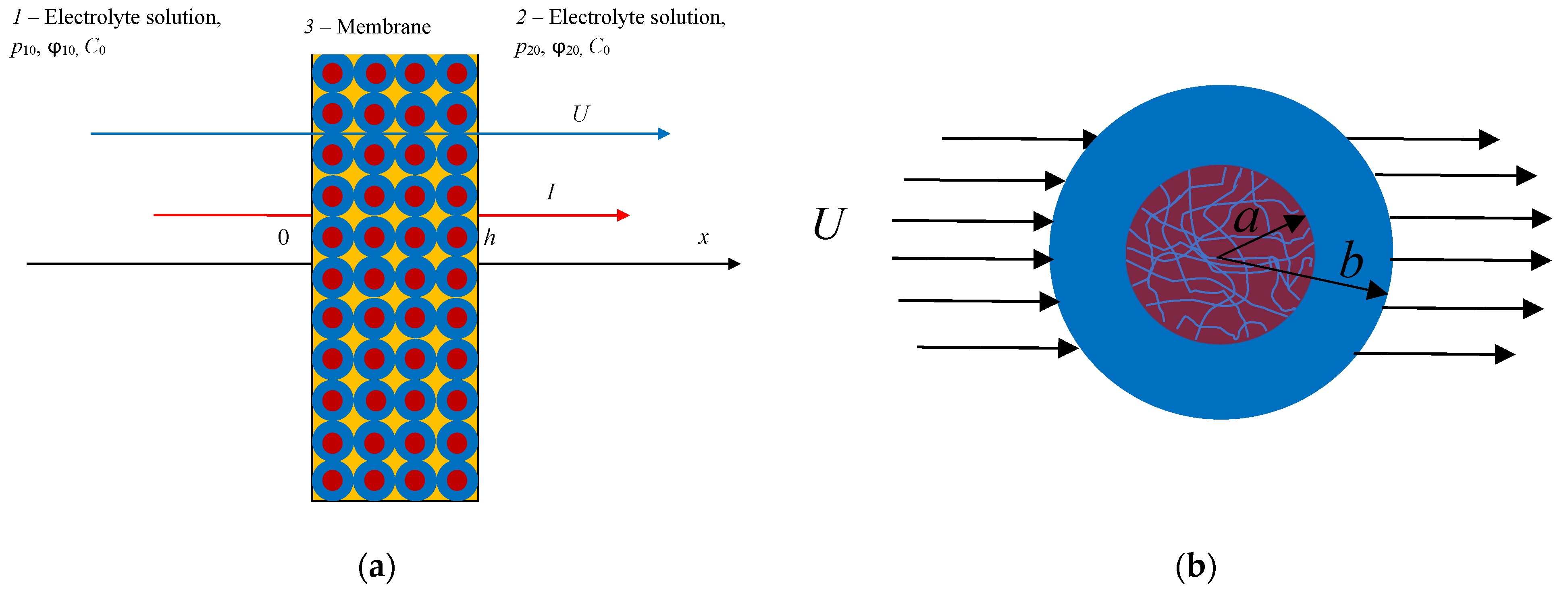
1]. The creation of a cell model of a charged porous medium of a globular type involves the mental replacement of a real system of chaotically arranged grains that make up this medium, carrying, as a rule, a negative charge, with a periodic lattice of identical porous balls enclosed in liquid spherical cells and having some constant density of fixed groups (exchange capacity). In this case, the action of neighboring particles is considered by setting special boundary conditions on the surface of liquid spherical shells. The advantage of this approach is that all quantities included in the transfer equations—thermodynamic fluxes and forces—can be directly measured in experiments. In [
2], the cell model of an ion-exchange membrane was created, the problem of finding the kinetic coefficients of the Onsager matrix was set up and solved in the general form, and an exact algebraic formula for the hydrodynamic permeability of a charged membrane was obtained for the first time. In [
3], in the framework of thermodynamics of nonequilibrium processes, based on the previously proposed cell model of a charged membrane [
2], the electroosmotic permeability and specific electrical conductivity of an ion-exchange membrane, considered as kinetic coefficients of the Onsager matrix, were calculated. Here, we will use the results of the mentioned works and apply them to the calculation of the transfer of solvent (water) and electric current through a charged porous layer (membrane) in contact with an aqueous solution of a binary 1:1 electrolyte. In this study, as in [
2,
3], we choose pressure gradients and electric potential as follows:
and
, respectively, as independent thermodynamic forces set during the experiment—the gradient of the chemical potential (the concentration gradient of the electrolyte) is absent. Here,
h is the thickness of the porous layer, and the indices “1” and “2” indicate the left and right sides of the porous layer, which are in contact with an equilibrium solution of a binary electrolyte of constant concentration
(
Figure 1a).
As dependent thermodynamic parameters determined in the experiment, we take the densities of solvent (water) flows,
, and mobile charges (electric current density),
. As for the flux of solute (salt), which can also occur when pressure gradients and electric potential are applied, for simplicity, we do not consider it here. Then, the phenomenological transport equations in the case of isothermal processes can be written as the following system of equations:
In accordance with the Onsager reciprocity principle, the matrix of kinetic coefficients must be symmetric, i.e.,
. However, as shown in our recent work [
4], this property ceases to be valid in our case. This fact is confirmed by the results of [
5], in which it was phenomenologically proven that, in the case of linear nonequilibrium thermodynamics, the symmetry of the matrix of kinetic coefficients is observed only in the special case of generalized thermodynamic fluxes being equal to zero and thermodynamic forces not being equal to zero. Here, we will discuss the calculation of the hydrodynamic
, electroosmotic
permeabilities, the kinetic coefficient
determining the streaming current, as well as the specific electrical conductivity
of the charged porous layer, which can be found by the formulae following from (1):
These relations (2) mean that the correct measurements of coefficients and are possible only in the absence of concentration and electric potential differences and a given constant pressure drop on the layer. The correct measurements of coefficients and are possible only in the absence of concentration and pressure differences and a given constant electric potential drop .
2. Statement of the Problem
Here, we will model a charged layer of a cellular-globular structure by a periodic lattice of porous charged spherical particles of the same radius
enclosed in liquid spherical shells of radius
, which is chosen in such a way that the ratio of particle volume to cell volume equals the volume fraction of particles in a dispersed system (porous layer):
where
is porosity available for filtration, or
active porosity—
Figure 1b.
The cell method makes it possible to reduce the problem of determining the kinetic coefficients of an entire layer to a boundary value problem for a single cell. The mathematical formulation of the problem for a single cell is given in [
2,
3] and is not given here for brevity. The designations of variables and parameters completely coincide with those in the articles [
2,
3] and are presented for convenience at the end of the article. The motion of an incompressible fluid (an aqueous electrolyte solution) in the outer region
of the cell is described by the vector differential Stokes equation at small Reynolds numbers (“creeping flow”), supplemented by a spatial electric force.
The fluid motion in the inner porous region
obeys the Brinkman vector differential equation [
6], complicated by a similar spatial electric force as in the outer region. Traditionally, the “Brinkman fluid” is assumed to be incompressible.
The electric potential satisfies the Poisson equation inside and outside the porous particle, and the Nernst–Planck representation is used for the density of ion fluxes. At the same time, there are no sources and drains of charges in the system, and the problem is considered in a stationary formulation. Assuming the Debye radius to be extremely small compared with the particle radius, the presence of electric double layers (EDLs) is effectively replaced by jumps in electric potential and ion concentrations when passing through the geometric interface of a porous grain/electrolyte solution [
2,
3]. At the same boundary, we set conditions for the equality of electrochemical potentials, velocities, total voltages, and radial components of ion flows. On the outer boundary of the cell, the Kuwabara condition is set—the absence of vorticity and the continuity of the radial velocity component.
Let, as previously in [
2,
3],
be the absolute value of the volume density of fixed charges of the porous skeleton (exchange capacity). For certainty, we assume the charge of the particle
to be negative. This is true, for example, in the case of sandstones or clay beds, then
. It should be noted that there are several experimental methods for determining the exchange capacity. The reservoir rock exchange capacity can be found by continuous potentiometric titration against the background of a NaCl solution [
7]. The charge density of fixed groups in the membrane can also be estimated by measuring the streaming potential [
8].
For the convenience of the analysis, we will use the same parameters as in [
2,
3]:
where
is the characteristic thickness of the filtration layer (Brinkman radius);
is the specific permeability of the structural grains that make up the formation; and
are the viscosity of the liquid in the shell surrounding the grain and in the grain itself. The parameter
s0 reflects how deep the fluid flow penetrates into the particle—the smaller this parameter, the stronger this penetration.
3. Discussion of the Theoretical Results
The hydrodynamic permeability of a negatively charged porous layer (membrane) in an aqueous solution of 1:1 electrolyte was determined based on the cell model in [
2]. In the simplest calculation case of an ideally selective membrane (negative sorption of ions located in the pores of the layer is observed), it is equal to the following:
where
и
are the diffusion coefficients of ions in dilute solution and porous layer, respectively;
is the reduced exchange capacity;
is the characteristic exchange capacity of the problem under consideration;
is the Faraday constant;
is the universal gas constant; and
is the absolute temperature. The characteristic exchange capacity
is reverse proportional to the specific hydrodynamic permeability of the structural grains and does not depend on the charge properties of the membrane. However, the behavior of kinetic coefficients depends on whether
is greater or less than the exchange capacity
of the membrane.
It follows from Formula (5) that, with an increase in the concentration of the electrolyte, the additional term to the unit in the denominator of the first fraction in the square bracket monotonically decreases from the positive value
at
to the negative value
at
. Therefore, as the concentration
increases, the hydrodynamic permeability will continuously increase, monotonically approaching its asymptotic value:
It should be noted that the monotonic approach of the hydrodynamic permeability curve (5) to a constant value (5a) with an increase in the electrolyte concentration corresponds to the nature of the dependence of the rate of extraction of petroleum products from the purified liquid on the concentration of calcium chloride by flocculation with the addition of cationic polyacrylamine and copolymer dimethylamine and epichlorohydrin [
9]. An increase in the exchange capacity
of the membrane, as also follows from Formula (5), has a complex effect on the hydrodynamic permeability—a maximum is observed on this dependence at the value
. With a further increase in the exchange capacity, the permeability
begins to decrease, tending to a value lower than that for an uncharged layer:
An increase in the characteristic exchange capacity of the problem with the selected electrolyte means a decrease in grain permeability while maintaining the porosity of the layer. It is quite natural that this leads to a drop in the overall permeability of the layer.
The specific electrical conductivity of the membrane was calculated in [
3] and, in the case under consideration of an ideally selective structure and a 1:1 electrolyte, it is given by the following expression:
Expression (6) consists of two terms: the first term determines the electrical conductivity of the electrolyte solution located between the grains of the layer, and the second one determines the electrical conductivity of the ionite grains themselves saturated with electrolyte. Dependence (6) has the sloping asymptote:
Various cases of the asymptote location are studied in detail in [
3].
As for
the electroosmotic permeability of an ideally selective cation-exchange layer relative to a 1:1 electrolyte, it can also be calculated for the particular case considered here; just as in [
3], the adjoint coefficient
L21, which determines the streaming current, was calculated:
In this case, dependence (7) has the following horizontal asymptote:
and dependence (8) has another horizontal asymptote:
Comparing (7) and (8), as well as (7a) and (8a), we conclude that they, although only slightly, differ (because and ). That is, the Onsager principle of reciprocity is violated here.
Note that, in the case of non-ideality of the layer, it is necessary to consider the potentials of specific (non-electrical) interaction of ions with the surface of its pores. To do this, the coefficients of the equilibrium distribution of cations and anions
in a porous matrix are introduced, where
is the Boltzmann constant. Potentials
characterize the total energy required to move ions from a bulk solution to a pore and represent the sum of interaction potentials of various nature: Van der Waals forces, image forces, and Born forces. At the same time, it is known that the greatest contribution to the value of
is given by the Born forces [
10], i.e., the forces associated with damage of the structure of hydrate shells of the anion/cation and the structure of water in the pore when the ion moves from bulk solution into the pore.
4. Results of Calculations
Using Formulas (5)–(8) and the Onsager relations (1), it is possible to calculate the solvent flow density (linear velocity
) and the electric current density
at any values of pressure gradients and electric potential. This means that it is possible to regulate the solvent flux and the electric current passing through the porous charged layer by changing the external electric field at a constant pressure gradient. The calculations were performed using the Mathematica 12 application software package and are shown in
Figure 2,
Figure 3,
Figure 4 and
Figure 5.
To estimate the relative influence of an external electric field on the linear velocity of a solvent (water) through a charged porous layer, we will use the ratio
and to assess the effect of the electric field on the electric current density, we will use the formula
where
are the linear velocity of the solvent flow and the streaming current density only in the presence of a pressure gradient on the porous layer;
are the flow velocity and current density under the action of pressure and electric potential gradients;
is the dimensionless electric potential; and
is the dimensionless pressure. The proportionality coefficients in the case of coincident viscosity values
are easily determined from expressions (1) and (5)–(8):
Note that, in the case of pressure gradients and electric potential of the same sign, the coefficient
linearly increases with
and the coefficient
also monotonically increases with the growth in
, asymptotically approaching its limiting value:
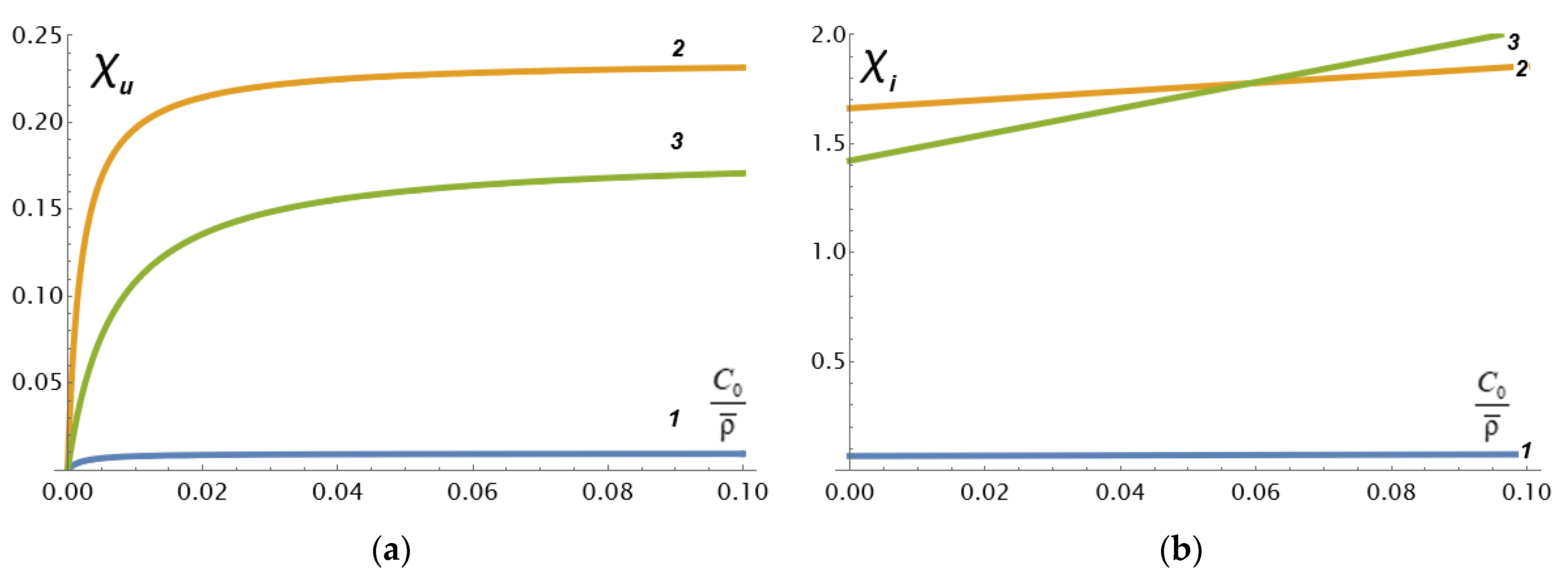
The dependences
calculated by Formula (11) with an increase in the relative concentration
of the electrolyte are shown in
Figure 2 in the case of values of the physicochemical parameters that are typical for the cast cation-exchange membrane MF-4SC (the Russian analogue of Nafion) in HCl solution investigated in our work [
11].
From
Figure 2a, it can be seen that an increase in
(decrease in the grain permeability or an increase in the grain size) by 5 times leads to an increase in
by 20 times (curves 1 and 2), and an increase in porosity
by 3 times leads to a decrease in
by about 30% (curves 2 and 3). It can also be concluded that the asymptotic value (9a) is practically achieved already at very small relative concentrations of the electrolyte. At the same time, Formula (12) implies a linear increase in the coefficient
on the relative concentration
of the electrolyte, and a directly proportional increase on the parameter
.
Figure 2b shows these linear dependencies. Moreover, it can be seen that, with large
(low hydrodynamic permeability of porous grains) increases in porosity, this first leads to a relative decrease in the coefficient
compared with lower porosity, and then the difference between the coefficients weakens and disappears at
. A further increase in the relative concentration of the electrolyte leads to the fact that the coefficient
increases faster with a larger macroscopic porosity than with a smaller one. Such behavior of
is explained by the complex nature of the interaction between the streaming current due to convective ion transport and the conductivity of the solution due to the imposition of an external electric field.
Thus, the imposition of an external electric field on a negatively charged layer, the intensity vector of which is co-directed with the velocity of
barofiltration (filtration under imposition of a pressure drop), leads to an increase in the rate of liquid transfer through the porous layer due to the addition of an electroosmotic component to the convective flux. When an electric field acts in the opposite direction, the solvent flow is inhibited. A similar pattern is observed for the electric current density.
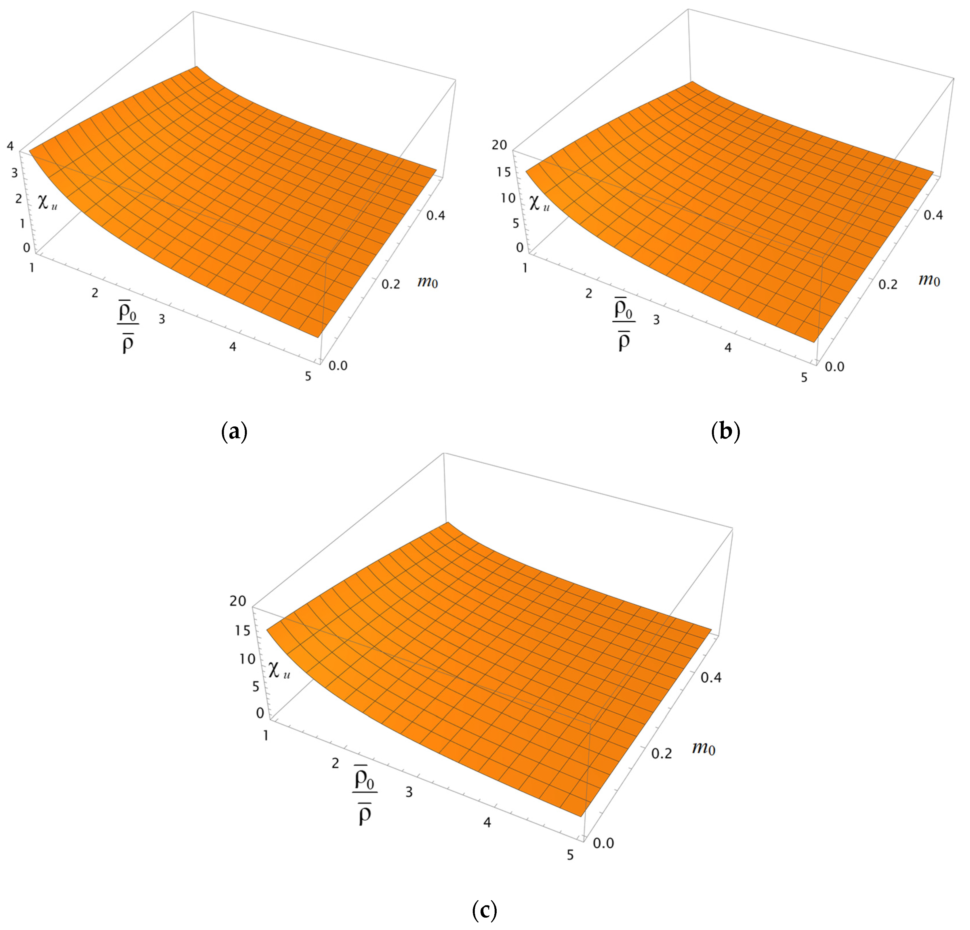
Figure 3a–c show surfaces depicting the behavior of the coefficient
depending on the porosity
and the ratio of the characteristic volumetric capacity of the layer to its actual capacity
at two different values of the relative concentration of the electrolyte (
= 0.1 and 0.5) and a given ratio of the diffusion coefficient of the counterion in the bulk solution to its value inside the porous layer—
. This ratio value is typical for the perfluorinated MF-4SC membrane and hydrochloric acid solution [
11]. At the same time, we have
> 1. We assume that the above-mentioned parameters remain approximately the same for a charged oil reservoir. However, based on the analysis of Formula (11), the parameter
does not significantly affect the coefficient
. The behavior of the coefficient
in
Figure 3a–c, depending on the porosity
m0 and the parameter
, is qualitatively similar, asserting the decrease in
with the growth in these parameters. As can be seen from
Figure 3, the increase in the rate of solvent transfer through the porous layer is strong with the increasing parameter
(thinning of the Brinkman filtration layer in the grains that make up the porous layer) and almost weakly depends on the relative concentration of the electrolyte
(
Figure 3b,c). Consequently, in practice, to improve the total permeability of an oil-bearing reservoir, it is most advantageous to pre-apply methods of chemical or physical modification of the reservoir to reduce the specific permeability
of its grains. At the same time, a synergistic effect is observed as the characteristic exchange capacity
also increases.
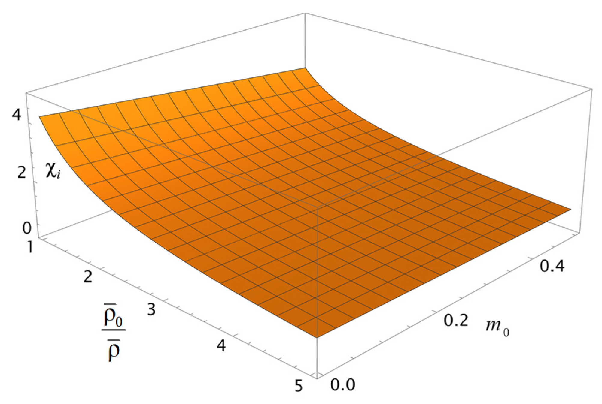
Note that the qualitative behavior of the coefficient
depending on the porosity
and the ratio
of the characteristic volumetric capacity of the layer to its actual capacity, shown in
Figure 4, is similar to how the coefficient
behaves (
Figure 3a). The mentioned observation reflects the generality of the pattern of charge and solvent transfer through a porous layer.
It should be mentioned that, in accordance with Formulas (11) and (12), the changes in the rate of solvent transfer through the layer and the density of the electric current depend not only on the dimensionless parameters
and
, accordingly, but also on the ratio of dimensionless gradients (differences) of the electric potential and pressure on the layer:
. Considering this and the relations (11) and (12), Formulas (9) and (10) can be rewritten explicitly:
Figure 5 shows the dependences (9a) (
Figure 5a) and (10a) (
Figure 5b) on the ratio of gradients
for the convenience of calculations measured in units of the inverse density of fixed charges of a porous skeleton
.
Analyzing
Figure 5a, we conclude that there are values of the electric potential gradient, opposite to the pressure gradient, at which the solvent transfer through the porous layer stops. At the same time, the values of the dimensionless ratio
are quite high:
for the set of parameters used, which are characteristic of the cast membrane MF-4SC [
11]. Considering that the electrodialysis process takes place at a voltage of the order of 1 V, and if we use the pressure during nanofiltration in the range of 1–10 bar, we have
. That is, the achievement of the above effect is quite real. Moreover, by increasing the negative gradient of the electric potential in absolute magnitude, it is possible to reverse the flow of solvent through a porous charged layer. The same applies to the direction of the electric current (
Figure 5b), but there the critical values of
that are 3–4 orders of magnitude lower. From
Figure 5a, it follows that the ratio
at small porosities weakly depends on the parameter
s0—curves 1 and 2 practically coincide. At the same time, with an average porosity of 30%, they differ markedly—curve 3 at
s0 = 1 lies above curve 4 at
s0 = 10. That is, with a lower permeability of the porous grains, the solvent transfer rate is also lower. It turns out to be smaller and with greater macroporosity
m0, which is quite understandable from a physical point of view. Note that, because the parameter
s0 is not included in Formula (10a), curves 1 and 2, 3, and 4 coincide in
Figure 5b. In the general case of a non-ideal membrane, these curves will differ as the ratio
depends on the parameter
s0.
It should be noted that the process of
electrobarofiltration (filtration under simultaneous imposition of a pressure drop and an electric field) studied here, when the direction of the electric field is opposite to the pressure gradient, can be effectively used to separate ions of the same sign and charge, for example, Li
+ and K
+ [
12,
13].
The cell model of an ion-exchange membrane that we explore here is only one of the possible interpretations of its complex structure and does not pretend to fully correspond to a real membrane. However, this mathematical model shows the same macroscopic properties as a real membrane, as shown in our works, for example, in [
11]. To do this, it is only necessary that the macroscopic porosity
m0 in the model formed by the ordered arrangement of spherical grains coincides with the real porosity of the membrane. For clarifying a structure of the Nafion ionomer suggested by well-known physicochemical models for ion-exchange membranes (like Gierke’s cluster, the local-order model, the polymer-bundle model, and others), previously published small-angle scattering data of hydrated Nafion are quantitatively simulated in [
14]. The main result of [
14] is the parallel water-channel (inverted-micelle cylinder) model of Nafion. Simulations for various other models of Nafion do not match the scattering data. The authors of [
15] reviewed different models describing ion transport in electromembrane systems, highlighting the role of micro- and macroheterogeneities. They paid attention to the models based on the irreversible thermodynamics approach, “solution-diffusion” and “pore-flow” models, as well as multiphase models built within the effective-medium approach.


