Abstract
This study presents the results of research on the use of Portland cement as a binder for producing semi-permanent molds intended for large-scale castings made from complex alloyed steels. Based on the conducted experiments, the optimal composition of a molding mixture based on Portland cement was determined to manufacture large molds with high operational performance. The technological properties of the mixtures were investigated, focusing on the flowability, sedimentation stability, and strength after curing. The recommended mixture composition is as follows: Portland cement—18.75%; sand—56.5%; quartz powder—25%; water—25%. To accelerate the hardening process, the use of curing accelerators is advised. The most effective additives are a 9% aluminum nitrate solution at 0.6–1.5% by weight or sodium aluminate at 3–4%. This composition ensures the required strength within a short curing time. A specific thermal treatment regime is also recommended to further stabilize the mold structure: heating to 450 °C at a rate of 75 °C per hour, holding for 2 h, followed by controlled cooling together with the furnace.
1. Introduction
Casting production remains the most widespread method for manufacturing component blanks. This is despite the development of various manufacturing technologies, including additive manufacturing, single-crystal growth, laser cutting, and others.
Increasing the metal utilization and the ability to produce finished parts without the need for additional machining can be achieved through specialized casting methods. The efficiency of a particular casting technique is primarily determined by the cost of mold production and the quality of the resulting castings.
Among the various casting methods, sand–resin molds remain one of the most widely used for producing cast blanks. This is largely due to their relatively low cost and the simplicity of mold preparation.
Meanwhile, cement has long been used as a binder due to its availability [1,2,3,4].
However, in rapidly advancing fields such as space exploration, aerospace engineering, and materials science, the use of cement–sand casting mixtures has not achieved the desired complexity of metal structure or high surface quality [5,6].
Cement-based molding mixtures currently have rather limited application in foundry production. Their use is mostly restricted to small-scale manufacturing of large steel and cast iron castings produced in single-use molds with permanent patterns [7,8,9].
The hydration and rheological properties of cement are discussed in [10]. The study characterized the hydration kinetics and hydration products of the mixtures in their fresh state.
It is well known that millions of tons of waste are generated in metallurgical production and subsequently disposed of in landfills. Reference [11] investigated the use of paraffin and ceramic additives in cementitious mixtures and evaluated the impact of varying the paraffin content on the physicomechanical properties of cement mixtures. The results demonstrated a reduction in the workability, water absorption, flexural strength, and compressive strength of the construction mixtures.
The authors of [12] established that the application of high-power ultrasound (US) to Portland cement paste leads to an increased concentration of aluminum in the pore solution. Signs of increased aluminate and carbonate content were observed in the cement paste. It was found that the addition of fillers to the ultrasound-pretreated paste resulted in a 17% increase in flexural strength after 28 days, indicating a possible modification of the paste–filler interfacial transition zone.
Researchers have investigated various microfillers as sand replacements to understand their impact on the hydration properties of Portland-cement-based materials (CBMs). Microfillers can exhibit two main effects: physical effects related to particle fineness, surface energy, etc., and chemical effects if they are reactive. In study [13], conventionally available fired clay bricks were ground to particles smaller than 150 µm and used at a 5% dosage in the mixtures to minimize their water absorption effect after sand replacement. Since mixtures containing brick powder demonstrated improved bulk electrical resistivity, it can be expected that such mixtures will also exhibit enhanced durability and bulk resistivity.
Study [14] investigated the effect of replacing natural aggregates with secondary aggregates in concrete pavers (CPBs). The replacement levels ranged from 0% to 100% for fine aggregates in mortars, and up to 50% for fine and/or coarse aggregates in concretes. The properties of the waste materials were analyzed, including the particle size distribution, porosity, water absorption, and density. For the cementitious mixtures, parameters such as the workability, consistency, density, compressive strength, electrical resistivity, and microstructure were evaluated. The results indicate that mortars containing CPB aggregates require higher dosages of superplasticizers to achieve the desired workability. This is attributed to the increased cement content per unit volume and the finer particle size of the recycled aggregates.
The enhancement of Portland cement’s strength through the use of various additives is discussed in studies [15,16,17].
Studies [18,19,20] focus on the use of Portland cement in combination with other components and the properties of such mixtures.
The microstructural characteristics and properties of cementitious materials depending on their composition are discussed in study [21]. It was determined that the mechanical properties of the matrix depend on the duration and type of curing (the procedures used to accelerate cement hydration). The influence of microwave treatment on the hydration and microstructure development of Portland cement was examined in [22]. The study found that a uniform temperature distribution within the samples reduces damage. It also increases porosity, which usually results from large temperature gradients during thermal curing.
The study presented in [23] examines samples produced using ordinary Portland cement.
The hardening of Portland cement during water curing is associated with its gradual hydration. This process leads to the formation of crystalline intergrowths of calcium and calcium–aluminate hydrosilicates. As a binder material, Portland cement possesses several important advantageous properties [24,25,26]:
- Compared to sand–clay molds, it provides a higher surface quality of castings produced in cement-based molds.
- Compared to organic binders, it is harmless, environmentally friendly and abundant.
- Compared to other crystalline hydrate binders, such as gypsum, it is more heat-resistant, refractory, cost-effective, and readily available.
- Low cost.
- No need for mold compaction.
- Ability to harden in air without additional drying.
- Environmental and sanitary safety.
- Low gas evolution.
- Satisfactory technological properties, including heat resistance.
- It ensures a clean casting surface. The low-melting cement particles on the surface of cast iron and steel form a light-blue oxide film (Fe oxides), which can be easily removed.
The advantages of Portland cements largely determine their suitability for use, particularly in large and caisson molds. These advantages include the low cost, environmental and sanitary safety, as well as satisfactory technological properties, notably heat resistance [27,28,29].
The use of aluminous (or aluminate) and high-alumina cements in mixture preparation enhances the strength and reduces the hardening time of sand–cement mixtures [30,31,32,33,34].
The objective of this study is to determine the optimal composition of a Portland-cement-based molding mixture intended for the manufacture of large casting molds with superior performance and operational reliability.
2. Materials and Methods
This study focused on various formulations of self-leveling cement mixtures based on Portland cement grade PC-400 (Central Asia Cement, Karaganda, Kazakhstan). The compositions of the experimental mixture samples are presented in Table 1.

Table 1.
Compositions of samples for testing.
The experimental mixtures were tested for properties such as the flowability and setting rate.
The flowability of the cement slurry was determined in accordance with GOST 26798 [35] using a KR-1 cone (Figure 1).
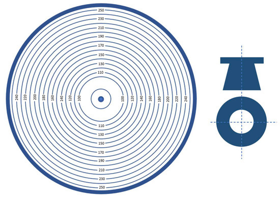
Figure 1.
KR-1 cone for determining slurry flowability (adapted from [9]).
The KR-1 cone consists of a base and a sampling cone. The sampling element is a truncated cone with a volume of 120 cm3, a top diameter of 37 ± 0.5 mm, and a height of 60 mm. The cone must have a minimum weight of 300 g. The cone is manufactured from stainless steel or plastic.
The base consists of two connected circular plates. The lower plate is made of metal, while the upper one is made of transparent glass. Concentric circles spaced at mm intervals are marked on the metal plate.
Scales with a division value of 5 mm are marked on the lower plate. The KR-1 cone is positioned horizontally on a table using leveling screws. The sampling cone is placed at the center of the base in such a way that its outer circumference aligns with the initial circle of the scale.
The test slurry is poured into the cone up to the upper edge of the ring. Then, the cone is sharply lifted, and after 10–12 s, the maximum and minimum diameters of the spread circle are measured. The flowability of the slurry is determined as the average diameter of the spread. According to GOST 1581-96 [36], cement slurry is considered flowable if its flowability reaches 150 mm.
The setting rate was determined by measuring the change in compressive strength. Standard cylindrical samples with a radius (R) of 50 mm and height (H) of 50 mm were used for the compressive strength tests. A hydraulic press model 04116A was employed to test the samples’ strength. To apply the load to a limited area of the fractured samples, special steel plates with a radius of 50 mm were used. The cylinders were clamped between these plates and inserted into the press. The strength limit was calculated as the arithmetic mean of four tests.
3. Results and Discussion
Three mixture compositions containing 25%, 20%, and 15% water were investigated, with a Portland-cement-to-sand ratio of 1:4 (Table 1).
At the initial stage, the flowability of the experimental mixtures was assessed. Flowability characterizes the fluidity of the slurry and its ability to fill complex mold geometries.
Measurements were taken starting from the moment the mixtures were prepared, at 20 min intervals. The experimental results are presented in Figure 2.
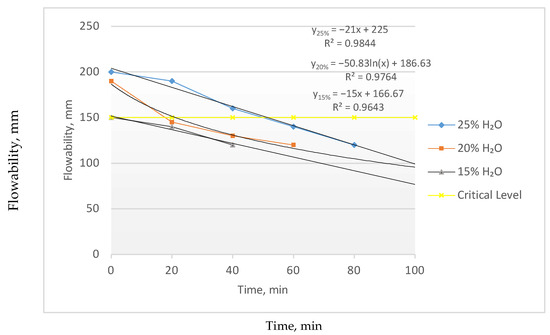
Figure 2.
Flowability of the experimental mixtures.
As shown in Figure 2, a water content of 15% does not ensure sufficient flowability of the mixture. From the standpoint of mold filling, such a mixture would be unsuitable. As the water content increases, the flowability of the mixture improves: at 25% water content, the flowability remains above the minimum acceptable level even after 40 min of testing.
However, visual observations revealed that a higher water content leads to a decrease in the sedimentation stability of the mixture. This significantly degrades the overall quality and limits the usable working time of the mixture. Sedimentation stability refers to the ability of a dispersed system to maintain a uniform distribution of dispersed phase particles throughout the volume and to resist settling under the influence of gravity.
The sedimentation stability is a key technological property of any suspension, as it essentially determines both its storage duration and working lifetime. In this study, the sedimentation stability was visually assessed based on the time it took for a distinct boundary to appear between the sediment and the liquid phase.
The thickening of the molding slurry occurs gradually, over a period exceeding three hours, and is accompanied by sedimentation. Cement molds formed from such slurry exhibit non-uniform physicomechanical properties, which ultimately result in poor casting surface quality and crack formation during calcination.
To improve the sedimentation stability of the mixture, it was proposed to add a fine dispersed component in the form of quartz powder.
After conducting a series of experiments with varying quartz powder content, an optimal composition of the sand–cement mixture for producing semi-permanent molds was determined experimentally. The mixture composition is presented in Table 2.

Table 2.
Optimal composition of the sand–cement mixture.
Next, the setting rate of the sand–cement mixture in the presence of a setting accelerator was investigated. Table 3 presents several types of setting accelerators.

Table 3.
Setting accelerators for cement mixtures.
During the experiment, two accelerators were investigated: 9% aluminum nitrate solution and sodium aluminate.
Aluminum nitrate primarily facilitates the dissolution of calcium sulfate, aluminate, and alumo-ferrite phases immediately after mixing the sand–cement mixture with water, which accounts for the rapid setting of the mixture. Subsequently, calcium silicate and calcium oxide undergo hydration, forming crystals that contribute to the development of a strong structure in the hardening cement. It is worth noting that the hydration products crystallize not only on the surface of the grains but also within the liquid phase in the form of well-developed needle-like crystals. This creates favorable conditions for deeper cement hydration.
Aluminum nitrate was added to the experimental mixtures (Table 2) in amounts of 0.6%, 1%, and 1.5% by mass, relative to the base 100%.
The setting rate of the mixture is directly correlated with its strength: the higher the strength at the time of testing, the more advanced the setting process.
Strength measurements of the experimental mixtures were carried out at 24 h intervals. The results obtained are shown in Figure 3. The minimum required strength of the mixture is 1.5 MPa. Without a setting accelerator, the mixture reaches this strength only after 7 days.
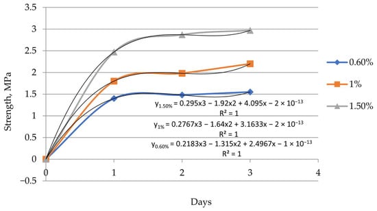
Figure 3.
Flowability of the experimental mixtures. The effect of aluminum nitrate content on the hardening rate of the mixture.
As shown in Figure 3, the setting rate of the sand–cement mixture increases with the rising content of the accelerator. The required strength of the mixture is achieved within one day. By the third day, the strength of the mixture containing 1.5% accelerator doubles. However, visual observations showed that increasing the accelerator content beyond 1.5% is undesirable, as it leads to crack formation.
Figure 4 shows the structure of an experimental sample without an accelerator and with the addition of 1.5% aluminum nitrate accelerator.
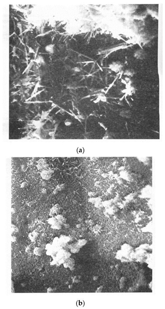
Figure 4.
Final structure of the hardened cement-bonded molding mixture before calcination, ×2500 ((a)—without accelerator, and (b)—with accelerator).
A structural comparison shows that the mixture with the accelerator exhibits a more homogeneous microstructure. The second-phase inclusions are more rounded and uniformly distributed, contributing to a less stressed overall structure.
As an alternative to aluminum nitrate, sodium aluminate was also used as a setting accelerator.
The main industrial method for producing sodium aluminate is the reaction of aluminum hydroxide (Al(OH)3) with a hot sodium hydroxide (NaOH) solution. For this purpose, the required amount of sodium hydroxide solution was loaded into a reactor, and aluminum hydroxide was gradually added under continuous stirring. Upon completion of the reaction, the resulting mixture was thoroughly cooled and filtered.
The effect of the sodium aluminate content on the sample strength was studied at hourly intervals after the samples reached handling strength. The experimental results are presented in Table 4 and Figure 5.

Table 4.
Setting accelerators for cement mixtures.
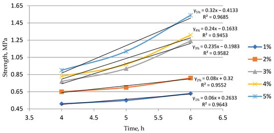
Figure 5.
Effect of the accelerator content on the setting rate of the mixture.
Analysis of the results shows a sharp increase in the setting rate when more than 3% sodium aluminate is added. However, adding more than 5% is not recommended due to the reduced workability of the mixture.
Mixtures containing 3% sodium aluminate exhibit satisfactory properties for the production of semi-permanent cement molds.
To determine the optimal calcination regime, three types of samples were studied. Tests were conducted on standard samples to check for cracks after calcination. After drying, the samples were heated up to 450 °C with a 2 h hold time, applying different heating rates. The results of the study are presented in Table 5 and Figure 6.

Table 5.
Setting accelerators for cement mixtures.
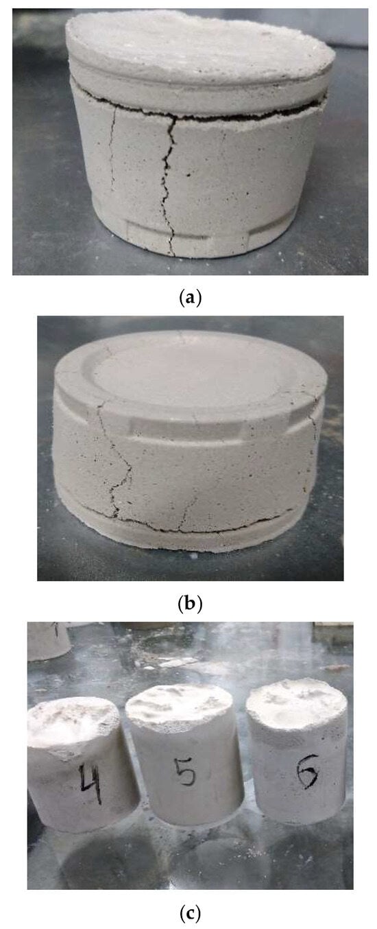
Figure 6.
Appearance of samples after calcination: (a)—heating rate 150 °C/h; (b)—heating rate 100 °C/h; and (c)—heating rate 75 °C/h.
Based on the experimental results, the optimal calcination regime for semi-permanent cement molds was determined as follows: heating to 450 °C at a rate of 75 °C per hour, holding at this temperature for 2 h, followed by furnace cooling.
Subsequently, mixture compositions were selected to meet the strength requirements both before and after calcination. Calcination in this case simulates the heating process of the mold after metal pouring. During the casting process, the mold temperature changes, which can lead to cracking, further dehydration, and other effects. All these processes result in a reduction in strength, which is undesirable but inevitable. To determine the extent of the strength loss due to these factors, strength tests were conducted after calcination.
This criterion is critical because semi-permanent cement molds must maintain high post-calcination strength. Such strength ensures the mold’s durability to withstand multiple metal castings.
Simultaneously, the composition of the core mixture was determined. In contrast to the mold mixture, the core mixture must lose strength after metal casting. This reduction in strength facilitates the easy removal of the cores from the casting. The results are presented in Table 6 and Figure 7.

Table 6.
Changes in the strength of samples after calcination.
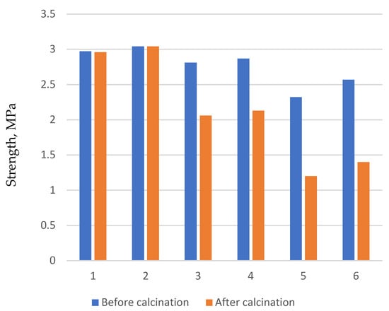
Figure 7.
Change in the mixture strength.
As a result, the optimal compositions for semi-permanent molds (Table 7) and cores (Table 8) were selected.

Table 7.
Composition of molding mixtures.

Table 8.
Composition of core mixtures.
To gain a better understanding of the solidification process in casting molds of different compositions, simulation calculations were performed. These simulations modeled the casting of an aluminum part called the “Lid” (see Figure 8). The calculations were carried out using the LVMflow software package 6.6.
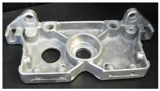
Figure 8.
Casting “Lid”.
Calculations were performed for several casting technologies, including the alpha-set process, hot-box process, cold-box process, and shell mold casting. These simulations aimed to compare the results with those obtained from casting into semi-permanent cement molds.
Identical initial data were entered for all the casting technologies, including the alloy material, pouring temperature, and mold preheating temperatures.
Figure 9 presents the solidification simulation results for the “Lid” casting using different molding mixtures.
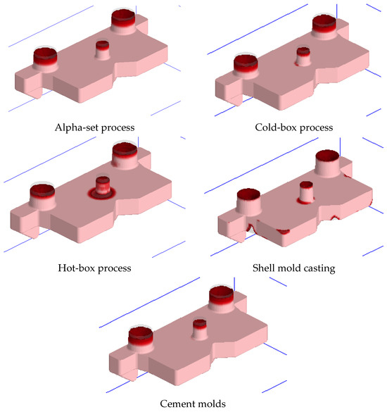
Figure 9.
Simulation results of casting using different mold materials.
In the figure, the bright red areas indicate zones where shrinkage cavities and underfilling occurred by the end of the solidification process.
When using the alpha-set process with cement molds, shrinkage cavities were confined to the feeders. In all other cases, shrinkage cavities formed within the body of the casting, which may lead to defects and potential part rejection.
Casting in shell molds typically results in defects such as shrinkage cavities and incomplete filling. In contrast, casting in cement molds does not produce such defects; any resulting shrinkage cavities can be eliminated during machining.
Based on the simulation results, it can be concluded that the cement mold casting technology yields performance comparable to existing precision casting methods.
Analysis of all the simulation scenarios related to casting with cement molds shows that the use of cold-hardening mixtures does not cause significant differences in defect formation. This is explained by the fact that after calcination, the mold composition closely resembles that of cement molds, with most binder components burned out, leaving approximately 90% sand content.
4. Conclusions
The conducted studies allowed for determining the optimal composition of a Portland-cement-based molding mixture for producing large casting molds with high performance properties. The recommended composition is as follows: Portland cement—18.75%; sand—56.5%; quartz powder—25%; water—25%. To accelerate the setting process, it is recommended to use setting accelerators. Aluminum nitrate at a 9% concentration in amounts of 0.6–1.5% or sodium aluminate in amounts of 3–4% are suggested as effective accelerators. Aluminum nitrate significantly accelerates the hydration processes of cement, promotes rapid early strength development, and reduces the molding cycle time. Sodium aluminate is an effective setting accelerator that enhances the early strength of the mold and reduces the water retention capacity of the mixture, facilitating faster moisture release.
The recommended mixture composition provides the required strength within a short setting time. To achieve the final strength, remove excess moisture, and enhance the thermal resistance of the molds after molding and initial setting, the following heat treatment regime is recommended: heating up to 450 °C; heating rate of 75 °C/h; holding for 2 h; cooling together with the furnace. This regime ensures uniform heating of the mold, prevents internal stresses and cracking, promotes strong bonding of the mixture components, and improves the quality of the finished casting molds. Using experimental mixtures based on Portland cement for producing molds in large-scale casting enables achieving the high strength and thermal resistance of the molds within a short time after molding, allowing the manufacture of large molds without prolonged natural drying.
Author Contributions
Conceptualization, V.K. and P.K.; data curation A.I.; methodology I.M. and S.K., formal analysis, S.A.; investigation, V.K. and S.K.; writing—original draft preparation, P.K. and I.M.; writing—review and editing, S.K., A.I.; visualization, S.A. All authors participated in writing the paper. All authors have read and agreed to the published version of the manuscript.
Funding
This research was funded by the Committee of Science of the Ministry of Science and Higher Education of the Republic of Kazakhstan (Grant No. BR24993020).
Data Availability Statement
The original contributions presented in this study are included in the article; further inquiries can be directed to the corresponding author.
Conflicts of Interest
The authors declare that they have no known competing financial interests or personal relationships that could have appeared to influence the work reported in this paper.
References
- Sanders, S.D.; Scott, E.D.; Sullivan, G.V. A Rapid-Set Cement Suitable as a Molding Sand Binder for Small Ferrous Castings; Department of the Interior, Bureau of Mines: Washington, DC, USA, 1980; p. 8417. [Google Scholar]
- Yilmaz, O.; Anctil, A.; Karanfil, T. LCA as a decision support tool for evaluation of best available techniques (BATs) for cleaner production of iron casting. J. Clean. Prod. 2014, 105, 337–347. [Google Scholar] [CrossRef]
- Kaur, I.; Siddiq, R. Mechanical Properties of Concrete Using Spent Foundry Sand. Master’s Thesis, Dimid University, Thapar Institute of Engineering and Technology, Leicester, UK, 2006; pp. 47–53. [Google Scholar]
- Abd Saloum, Q.; Abdullah, M.Z.; Hashim, A.A. The preparation of foam cement and determining some of its properties. Eng. Technol. J. 2015, 33, 61–69. [Google Scholar] [CrossRef]
- Upadhyay, M.; Sivarupan, T.; El Mansori, M. 3D printing for rapid sand casting—A review. J. Manuf. Process. 2017, 29, 211–220. [Google Scholar] [CrossRef]
- Günther, D.; Mögele, F. Additive manufacturing of casting tools using powder-binder-jetting technology. In New Trends 3D Print; InTech: London, UK, 2016; pp. 53–86. [Google Scholar]
- Kamal, M.M.; Safan, M.A.; Etman, Z.A.; Salama, R.A. Behavior and strength of beams cast with ultra high strength concrete containing different types of fibers. HBRC J. 2014, 10, 55–63. [Google Scholar] [CrossRef]
- Mohmad Ali, I. Development of Ship Propeller Using Dynamic Casting Method. Ph.D. Thesis, Universiti Putra Malaysia, Seri Kembangan, Malaysia, 2016. [Google Scholar]
- Martynov, K.V. Ceramic Molds on a Silica Sol Binder for Investment Casting. Ph.D. Thesis, St. Petersburg State University, Saint Petersburg, Russian, 2005. Abstract of the Dissertation for the Degree of Candidate of Technical Sciences. [Google Scholar]
- Wang, J.; Ji, X.; Chen, D.; Qian, C.; Liu, G. Hydration and rheological properties of municipal sludge co-processing cement. Case Stud. Constr. Mater. 2025, 22, e04126. [Google Scholar] [CrossRef]
- Cunha, S.; Tavares, A.; Aguiar, J.B.; Castro, F. Cement mortars with ceramic molds shells and paraffin waxes wastes: Physical and mechanical behavior. Constr. Build. Mater. 2022, 342, 127949. [Google Scholar] [CrossRef]
- Ehsani, A.; Ganjian, E.; Haas, O.; Tyrer, M.; Mason, T.J. The positive effects of power ultrasound on Portland cement pastes and mortars; a study of chemical shrinkage and mechanical performance. Cem. Concr. Compos. 2023, 137, 104935. [Google Scholar] [CrossRef]
- Shrivastava, M.; Tsegaye, H.; Kumar, S.; Harish, K.V. Assessment of hydration behaviour of Portland Cement-Based materials containing brick powders as partial replacement for fine aggregates. Mater. Today Proc. 2022, 65, 1095–1104. [Google Scholar] [CrossRef]
- Pizoń, J.; Matýsková, K.; Horňáková, M.; Gołaszewska, M.; Kratošová, G. Recycled concrete paving block waste as a selected sustainable substitute for natural aggregate in cement composites. Constr. Build. Mater. 2025, 478, 141356. [Google Scholar] [CrossRef]
- Wang, H.; Feng, P.; Liu, X.; Shi, J.; Wang, C.; Wang, W.; Li, H.; Hong, J. The role of ettringite seeds in enhancing the ultra-early age strength of Portland cement containing aluminum sulfate accelerator. Compos. Part B Eng. 2024, 287, 111856. [Google Scholar] [CrossRef]
- Liu, H.; Li, X.; Wang, L.; Li, L.; Zhou, Z.; Liu, Z.; Gong, L. Study on the anchoring properties of new water glass-modified alkali-activated portland cement materials. Constr. Build. Mater. 2024, 450, 138628. [Google Scholar] [CrossRef]
- Do Couto, Á.F.; Sandoval, G.F.B.; Schwantes-Cezario, N.; Christoni, A.R.F.; Cruz, R.J.P.; Da Silva, P.R.C.; Morales, G. Physicochemical evaluation of Eucalyptus Wood Ash as a mineral admixture in Portland cement matrices: A preliminary study. Case Stud. Constr. Mater. 2024, 21, e03860. [Google Scholar] [CrossRef]
- Chaves, L.R.d.C.; Heineck, K.S.; Filho, H.C.S.; Chaves, H.M.; Carvalho, J.V.d.A.; Wagner, A.C.; Silva, J.P.d.S.; Consoli, N.C. Field and laboratory study of iron ore tailings—Portland cement blends for dry stacking. Proc. Inst. Civ. Eng.-Geotech. Eng. 2025, 178, 31–40. [Google Scholar] [CrossRef]
- Yuan, J.; Chang, J.; Bai, Y. Preparation of supplementary cementitious material by semi-dry carbonated ternesite and its effect on hydration and mechanical properties of Portland cement. Cem. Concr. Res. 2025, 193, 107870. [Google Scholar] [CrossRef]
- Silva, J.; Azenha, M.; Correia, A.G.; Granja, J. Continuous monitoring of sand–cement stiffness starting from layer compaction with a resonant frequency-based method: Issues on mould geometry and sampling. Soils Found. 2014, 54, 56–66. [Google Scholar] [CrossRef]
- Bespalhuk, K.J.; de Oliveira, T.J.C.; Valverde, J.V.P.; Gonçalves, R.A.; Ferreira-Neto, L.; Souto, P.C.S.; Silva, J.R.; de Souza, N.C. Fractal analysis of microstructures in Portland cement pastes—Effect of curing conditions. Constr. Build. Mater. 2023, 363, 129881. [Google Scholar] [CrossRef]
- Yu, L.; Ma, J.; He, Y.; Lu, L. The effects and mechanisms of low-energy consumption microwave curing on the microstructure and strength development of cement-based materials. Constr. Build. Mater. 2025, 471, 140716. [Google Scholar] [CrossRef]
- Rahimi, M.Z.; Zhao, R.; Sadozai, S.; Zhu, F.; Ji, N.; Xu, L. Research on the influence of curing strategies on the compressive strength and hardening behaviour of concrete prepared with Ordinary Portland Cement. Case Stud. Constr. Mater. 2023, 18, e02045. [Google Scholar] [CrossRef]
- Ivanov, V.N.; Gagin, I.N. Prospects for the use of silica binder. Foundry Prod. 2000, 7, 42–43. [Google Scholar]
- Taylor, H.F.W. Cement Chemistry; Voikova, A.I.; Kuznetsova, T.V., Translators; Thomas Telford Ltd.: London, UK, 1997; p. 560. [Google Scholar]
- Solouki, A.; Aliha, M.R.M.; Makui, A.; Choupani, N. Analyzing the effect of notch geometry on the impact strength of 3D-printed specimens. Mater. Test. 2023, 65, 1668–1678. [Google Scholar] [CrossRef]
- Geng, Z.; Pan, H.; Zuo, W.; She, W. Functionally graded lightweight cement-based composites with outstanding mechanical performances via additive manufacturing. Addit. Manuf. 2022, 56, 102911. [Google Scholar] [CrossRef]
- Kääntee, U.; Zevenhoven, R.; Backman, R.; Hupa, M. Cement manufacturing using alternative fuels and the advantages of process modeling. Fuel Process. Technol. 2004, 85, 293–301. [Google Scholar] [CrossRef]
- Chen, W.; Pan, J.; Zhu, B.; Ma, X.; Zhang, Y.; Chen, Y.; Li, X.; Meng, L.; Cai, J. Improving mechanical properties of 3D printable ‘one-part’ geopolymer concrete with steel fiber reinforcement. J. Build. Eng. 2023, 75, 107077. [Google Scholar] [CrossRef]
- Arunothayan, A.R.; Nematollahi, B.; Khayat, K.H.; Ramesh, A.; Sanjayan, J.G. Rheological characterization of ultra-high performance concrete for 3D printing. Cem. Concr. Compos. 2022, 136, 104854. [Google Scholar] [CrossRef]
- Gartner, E.; Sui, T. Alternative cement clinkers. Cem. Concr. Res. 2018, 114, 27–39. [Google Scholar] [CrossRef]
- Huntzinger, D.N.; Eatmon, T.D. A life-cycle assessment of Portland cement manufacturing: Comparing the traditional process with alternative technologies. J. Clean. Prod. 2009, 17, 668–675. [Google Scholar] [CrossRef]
- Aranda, A.; Ferreira, G.; Llera, E. Characterization and environmental analysis of steel-making residues as cement manufacturing feedstock. In Proceedings of the Sixth Conference on Sustainable Development of Energy, Water and Environmental Systems, Dubrovnik, Croatia, 25–29 September 2011; p. 29. [Google Scholar]
- Ameri, B.; Taheri-Behrooz, F.; Aliha, M.R.M. Evaluation of the geometrical discontinuity effect on mixed-mode I/II fracture load of FDM 3D-printed parts. Theor. Appl. Fract. Mech. 2021, 113, 102953. [Google Scholar] [CrossRef]
- GOST 26798.1-96; Well Cements Test Methods. RussianGost: Moscow, Russia, 1998.
- GOST 1581-96; Well Portland Cements. RussianGost: Moscow, Russia, 1998.
Disclaimer/Publisher’s Note: The statements, opinions and data contained in all publications are solely those of the individual author(s) and contributor(s) and not of MDPI and/or the editor(s). MDPI and/or the editor(s) disclaim responsibility for any injury to people or property resulting from any ideas, methods, instructions or products referred to in the content. |
© 2025 by the authors. Licensee MDPI, Basel, Switzerland. This article is an open access article distributed under the terms and conditions of the Creative Commons Attribution (CC BY) license (https://creativecommons.org/licenses/by/4.0/).