1. Introduction
Short fibre-reinforced composites play an important role in modern lightweight construction, especially in semi-structural functions and structural functions outside the high-performance regime. Consisting of short fibres with lengths well below 1 mm, embedded in a disordered manner into a polymeric matrix, they have the advantage of being easily processed by means of standard and well-established manufacturing processes in polymer technology such as injection moulding. By this means, they may easily be processed into a variety of even complex shapes, allowing for the manufacturing of highly integrated composite structures. As has been shown, e.g., by Keyser et al. [
1], short fibre composites—depending on their constituents and their microstructure—may feature mechanical properties even up to the range of aluminium alloys. On the other hand, their processing requires significantly lower amounts of energy. However, the main disadvantage of short fibre-reinforced polymer composites, only rarely considered in the literature so far, is their random, disordered microstructure, triggering a significant uncertainty in their mechanical properties which is neglected in most available studies in the literature.
Due to their immense relevance in structural application, especially for industrial-scale components, numerous investigations on the mechanical response of short fibre composites have been published over the past few decades. Among these, the now classical contributions by Aboudi [
2], Hill [
3], Walpole [
4], and Willis [
5]—among others—date back to the early 1980s or, in the case of Hills’ [
3] fundamental contribution, even back to the mid-1960s.
The macroscopic material response of short fibre composites depends in a complex manner on their microstructure. In this context, not only the material response of fibres and matrix is relevant, but also the microstructural morphology in terms of the fibre diameter, fibre length, and especially the fibre orientation distribution. Further relevant effects derive from the interaction of neighbouring fibres and from the strength and toughness of the fibre and matrix interfaces.
To describe the local fibre orientation distribution, Advani and Tucker [
6] introduced their now well-accepted concept of fibre orientation tensors of different orders. Laws and McLaughlin [
7] investigated the effect of fibre length on the macroscopic stiffness of short fibre composites. Investigating a short glass fibre-reinforced PEEK material, Cai et al. [
8] provided a study on failure initiation in short fibre composites, revealing the development of complex local modes for damage evolution and failure initiation. These modes consist of fibre and matrix debonding around the fibre ends or between narrowly spaced fibres, growth and coalescence of these voids, fibre pull-out and possibly also a small amount of fibre fractures. A comprehensive study on the mechanisms controlling failure of short fibre composites and their interaction has been provided by Talreja [
9,
10,
11], with special interest being directed to damage evolution and failure under fatigue loads. These findings were confirmed in experimental studies by Arif et al. [
12] and especially in the tomographic analyses by Corbetta et al. [
13], revealing fibre matrix debonding and void formation around the fibre ends as the dominant mechanisms for damage and failure initiation in short fibre composites.
Due to the random disordered nature of the microstructure, all of these effects lead to uncertainty in both stiffness and strength of short fibre composites, as already pointed out in 1995 by Bijsterbosch and Gaymans [
14]. In this context, not only epistemic uncertainties due to inaccurate measurements or modelling techniques are present, but short fibre composites feature distinct aleatoric, physical uncertainties in their material response due to their uncertain morphology at the microstructural level (Sriramula and Chryssanthopoulos [
15]). A contribution by some of the present authors on the uncertainty of discontinuously fibre-reinforced thermoplastics using digital image correlation-based local strain measurements exhibits the development of a strong local variability in the local strain state of tensile specimens (Hohe et al. [
16]). To comply with the essential aleatoric uncertainty in the material response of short fibre composites, further stochastic modelling techniques have been provided in contributions (e.g., Bednarcyk et al. [
17], Rahman and Chakraborty [
18], Sepahvand and Marburg [
19]). A review pointing out the necessity of integrated consideration of processing and stochastic multiscale aspects in the holistic modelling of the mechanical response of short fibre composites has recently been provided by Proy et al. [
20]. Application of these stochastic modelling techniques essentially requires a profound and experimentally validated knowledge of the uncertainty in the material response and the related correlations between the uncertain properties as well as their spatial correlation.
The present contribution intends to fill this gap and to investigate the interrelation between microstructural morphological uncertainties and uncertainties in the macroscopic material response of short fibre composites. The reference material considered for this purpose is a short glass fibre-reinforced phenolic resin matrix material. The material response is investigated experimentally on different scales, using samples ranging from micro specimens with gauge section dimensions in the range of a few 100 microns to miniature specimens with 3 mm gauge section width, up to macroscopic, ISO-size specimens. In all cases, larger sample populations are tested to evaluate not just a mean value but also the probability distribution of the respective material parameters. The investigation on the coupon level is complemented by experiments on breadboard samples to account for more complex boundary and loading conditions. Further to the direct experimental investigation into the uncertainty in the material response of short fibre composites, the results of the present investigation serve as a reference database for a probabilistic multiscale simulation approach addressed in an upcoming contribution.
2. Materials and Methods
2.1. Reference Material
The material under investigation is a short glass fibre composite with a phenolic resin matrix. The material was manufactured using a thermoset injection-moulding process (Maertens et al. [
21]). The glass fibres had a diameter of approximately 13 μm and an initial length of 4 mm. After manufacturing, the fibre length was reduced due to breakages during the moulding process. The average length after moulding was found to be 378 μm with a distinct uncertainty. The material was supplied in the form of plane rectangular plates with outer dimensions of 480 mm × 190 mm featuring a central sprue. The plates were supplied with two different thicknesses of 2 mm and 3 mm, respectively. During manufacture, the mould temperature was adjusted to 175 °C. The plates were injected at an injection speed of 75 cm
3/s. Both compounding and injection moulding of the material were performed by Fraunhofer ICT at their Pfinztal laboratories. Full details on the material and the related manufacturing can be found in a study by Maertens et al. [
21].
The material was supplied in two batches. The first batch of the material was manufactured with a fibre mass fraction of 37.5 wt%. In the second batch, material with fibre mass contents of 28 wt% and 20 wt%, respectively, was supplied. The second batch also featured a slightly different matrix material formulation.
2.2. Sampling
The material was characterised mechanically on different length scales and with respect to different loading types, including tension, compression, and shear. More general conditions were considered in breadboard experiments.
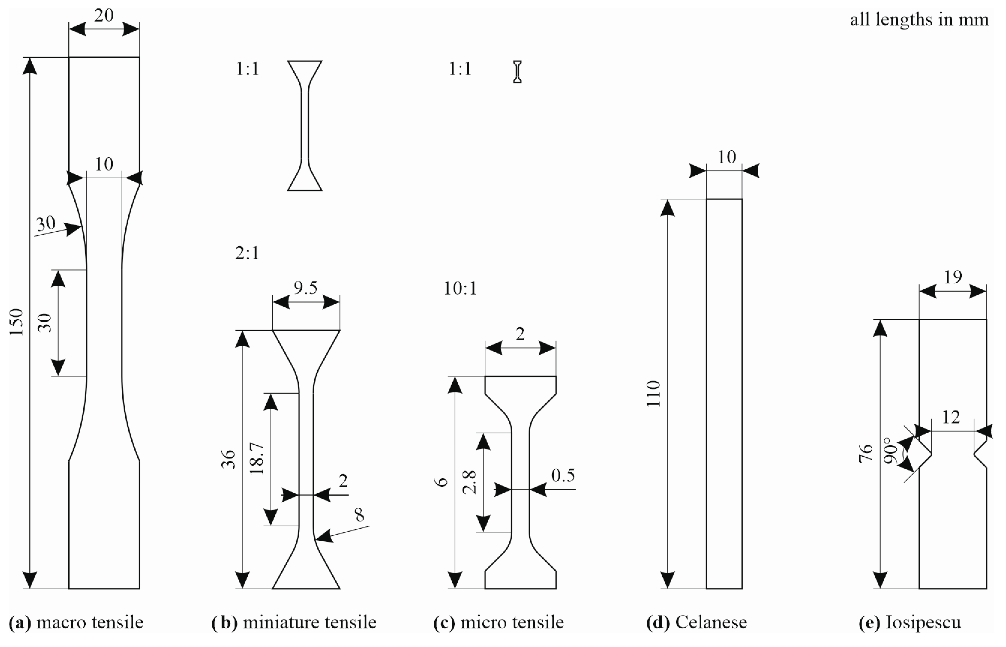
The quasi-static tensile tests were performed on samples of three different sizes. The macroscopic material characterisation was performed on ISO-size tensile samples according to ISO 527-4 [
22], with a reduced length of 90 mm and a width of 10 mm. On an intermediate scale, miniature samples with a length of 36 mm, a width of 2 mm, and fishtail ends for clamping were used. At the lowest scale, micro samples with gauge section widths of 0.2 mm and 0.5 mm, respectively, were employed. The exact specimen dimensions for all three levels are presented in
Figure 1. The compressive response was investigated in Celanese compression tests according to ISO 14126 [
23] with a sample length of 110 mm and a width of 10 mm. To investigate the shear response, Iosipescu shear specimens according to ASTM D5379/D5379M [
24] with a width in the centre of the sample of 12 mm were manufactured. The dimensions of the shear and compression specimens are also presented in
Figure 1.
Further to the coupon experiments, breadboard tests were carried out on square samples with in-plane dimensions of 190 mm × 190 mm and a thickness of 2 mm, manufactured from 37.5 wt% fibre plates and from plates with lower fibre mass contents (28 wt% and 20 wt%, respectively), with two types of mould temperatures (175 °C, 165 °C) and injection speeds (75 cm3/s, 50 cm3/s).
The samples for all experiments were manufactured using waterjet cutting. For all specimens except the micro specimens, the original plate thickness was used so that only the outer specimen contours needed to be cut. The basic material properties and their uncertainties were determined on samples from the batch with a 37.5 wt% fibre weight fraction. Additionally, ten tensile tests in the 0° direction were performed on the material variants with 28 wt% and 20 wt% fibre weight fractions, respectively, in order to study the effect of the fibre content and to make a connection to the breadboard experiments performed on these material variants. The sampling plan for the individual plates is presented in
Figure 2.
In the experimental investigation, the ISO-size specimens served mainly to investigate the variation in the mechanical properties between different plates manufactured under nominally identical conditions. The three types of macro specimens (ISO tensile, compression, and shear specimens) were distributed across the plates, as shown in
Figure 2a. Two ISO tensile and two compression specimens, in either the 0° or 90° direction, and two shear specimens were arranged on one half of the plates as indicated. Samples from fourteen plates with a thickness of 3 mm were tested.
The miniature tensile samples were employed to investigate the material variation across the plates. Therefore, 90 samples were extracted on a regular grid from one half plate with a 2 mm thickness oriented in the 0° direction. In a similar manner, 85 samples oriented in a 90° direction were extracted from another half plate.
The micro tensile samples were manufactured from a square precursor taken from the centre of the plates (see
Figure 2a). From the precursor, thin slices were prepared by grinding and polishing on both sides until the desired thickness of 0.2 mm was reached. Finally, the dog-bone shape of the micro samples was manufactured by micro-CNC milling using a custom-made fixture. A detailed description of the micro specimen preparation process is given in a contribution by Fliegener et al. [
25]. A compilation of all samples for testing on the material and breadboard levels is given in
Table 1 and
Table 2. All samples were conditioned to 23 °C and 50% relative humidity prior to testing.
2.3. Mechanical Characterisation
The macro (ISO-size) tensile specimens, Celanese specimens, and Iosipescu specimens were tested according to the respective test standards, i.e., ISO 527-4 [
22], ISO 1426 [
23], and ASTM D5379 [
24], respectively. All tests were performed on an electromechanical testing machine (Hegewald & Peschke inpekt Table 250). The tests were performed under quasi-static conditions at a prescribed crosshead velocity until failure. For the tensile experiments, a crosshead velocity of 4 mm/min was applied to achieve a similar strain rate to that for the miniature specimens. The shear and compression samples were both tested at a crosshead velocity of 1 mm/min. During the experiments, the crosshead displacement, the resulting force
, and—for the tensile and compressive tests—the elongation
of a prescribed initial length
were continuously recorded. The results were evaluated in the usual manner for the engineering stress:
with the initial cross-section
A0 and the engineering strain:
where an optical digital image correlation system (GOM ARAMIS) was used for the continuous determination of the elongation
. A similar procedure was employed to determine the engineering shear stress vs. engineering shear strain curves in the Iosipescu shear experiments. In all cases, the obtained engineering stress–strain curves were evaluated for the Young’s or shear moduli
or
, respectively, the strength
and the fracture strain
according to the procedures of the respective standards.
The miniature samples were tested in a similar manner under quasi-static conditions at a crosshead velocity of 1 mm/min until failure. The strain of the miniature samples was measured by an extensometer with an initial length of = 10 mm. The evaluation followed the same procedure as for the tensile experiments on the macro, i.e., ISO-size specimens.
The micro tensile tests were performed using a setup developed by Kennerknecht [
26] for metallic materials and later adapted to discontinuously fibre-reinforced materials by Fliegener et al. [
25]. The test device is driven by a linear motor and/or a piezo actuator. An optical microscope with a camera was used to continuously measure the surface displacement in the centre of the specimens. In this context, the microstructure on the surface of the micro samples is employed directly as a speckle pattern for the optical strain evaluation using digital image correlation by means of a greyscale correlation system. The micro tests are evaluated in the same manner as their macro and miniature counterparts for the Young modulus
, the tensile strength
and the fracture strain
.
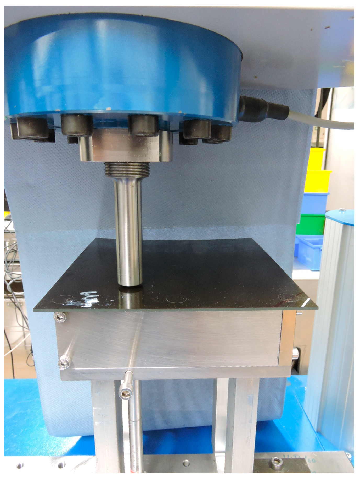
To include some more general asymmetric and multiaxial loading situations into the investigation, breadboard experiments were employed. For testing, square 190 mm × 190 mm samples were placed onto a square frame, such that simply supported boundary conditions were obtained on a square area of 150 mm × 150 mm. The specimens were indented normally by a spherical punch at an asymmetrically located position. The sphere radius of the punch was 20 mm, with the load point being located in the upper right corner of the plates. The exact load point was located 50 mm and 30 mm apart from the inner boundary of the support frame in the
and
directions, respectively. A photo of the test rig is presented in
Figure 3.
The breadboard specimens were loaded under quasi-static conditions until substantial cracking emanated from the load point. During the experiments, the resultant force and the crosshead displacement were recorded continuously. Ten samples with a fibre mass content of 20 wt%, ten samples with 28 wt%, and five samples with 37.5 wt% were tested. In addition, ten samples each with 20 wt% and 28 wt% fibre weight fractions from plates manufactured at a reduced injection speed of 50 cm
3/s and a reduced tool temperature of 165 °C were investigated. The test conditions and specimen numbers are compiled in
Table 2. The experiments were evaluated with respect to the overall load vs. displacement curve. From the results, the force
at the first substantial drop in the resulting force displacement curve was determined, in all cases coinciding with the instant of the development of substantial cracking. As a second parameter, the cumulative crack length
, i.e., the cumulative length of cracks, observed on the plate surface after this event was determined. A nominal crack area
was determined as the product of the cumulative crack length and the plate thickness.
2.4. Fibre Orientation Distribution
The local fibre orientation distribution of the material is described in terms of the second-order fibre orientation tensor (FOT) suggested by Advani and Tucker [
6]:
where
is the number of fibres in the considered control volume, whereas
are the components of the normalised direction vector of the
-th fibre. In order to analyse both the local uncertainty in the fibre orientation and the (process-dependent) variation in the fibre orientation across the injection-moulded plates, the fibre orientation was determined on a regular grid across a selected plate. To achieve a direct correlation of the local fibre orientation and the local effective material properties, samples for the determination of the fibre orientation tensor were taken from the specimen heads of the miniature samples after testing.
For the samples in the 0° direction, the lower sample head was evaluated (
Figure 2b), whereas the left-hand specimen head was evaluated for the samples tested in the 90° direction (
Figure 2c). For this purpose, the sample heads of the broken specimens were ground and polished at a depth of 100–200 μm from the surface. The fibre orientation tensor was determined with respect to the coordinate system in
Figure 2 from micrographs covering an area of 1.3 mm × 1.6 mm. Image segmentation and evaluation of the components of
according to Equation (3) were performed using a semi-automated procedure. In this context, fibres located too close to each other to be detected automatically were separated manually.
4. Discussion
Different mechanical investigations were performed to analyse the uncertainty in the material properties of short fibre-reinforced thermoplastics. The tests on ISO-size tensile specimens in the 0° and 90° directions, which were extracted at different positions of the injection-moulded plates, exhibit an anomaly in the scatter-band width of the specimens in the 90° direction (
Figure 4a). The significantly higher scatter-band width of the results based on specimens extracted at a position far from the sprue in contrast to the specimens with a position close to the sprue (see
Figure 2) can be explained by the fact that near the sprue, the probability of obtaining a microstructure with similarly orientated fibres is much higher than that far away at the plate edges after a pronounced flow distance. Also, edge effects during the moulding process become more significant at this position.
A comparison between the ISO-size and miniature tensile test results shows a comparable scatter-band width for the specimens in the 90° direction (
Figure 4a,b). The significantly smaller scatter-band width in stress–strain curves of the ISO-size specimens in comparison to the miniature specimens in the 0° direction can be explained by the original specimen positions in the plates. The ISO-size specimens were entirely extracted close to the plate edges, whereas the miniature specimens were extracted at positions on a regular grid spread over the entire plate area.
Furthermore, it is well known that the scatter-band width of stress–strain curves increases with decreasing cross-sections due to less pronounced self-averaging effects. This is confirmed by the results of the micro tensile tests (
Figure 4c), where the scatter-band width of the stress–strain curves is significantly larger in comparison to the miniature specimens, although the micro specimens were exclusively extracted from an originally centred position in the plates (see
Figure 2). An explanation for the similar results when testing in the 0° and 90° directions might be the fact that the influence of the dominant fibre orientation on the measured stress–strain curve is negligible when testing with a rather small cross-section where the fibre length is in the same range as the gauge section width of the specimen and other local characteristics such as defects become much more relevant for the material behaviour.
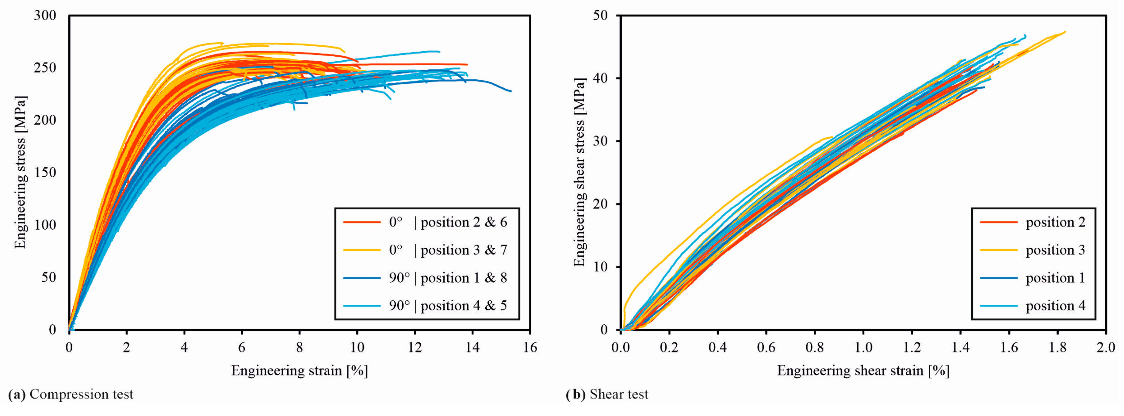
In the stress–strain curves of the compression tests, an influence of the original specimen position in the plate is not visible (
Figure 8a). A reason might be that all specimens have a sufficiently large distance to the plate edges as well as to the sprue. Since the shear specimens are cut out at neighbouring positions in the centre of the half plates, a common scatter band of the stress–strain curves is the expected result (
Figure 8b).
In the representation of the probability distributions for the Young’s moduli of the tensile specimens with different sizes, the higher values for the micro specimens compared to the ISO-size and miniature specimens are conspicuous (
Figure 5a). Nevertheless, it needs to be considered that—although the Celanese and Iosipescu specimens have outer dimensions in the same order of magnitude as the ISO-size tensile specimens—their test section, i.e., the highly loaded volume, is much smaller than for their tensile counterparts. In this context, the Celanese specimens are clamped over most of their area, leaving a test section in the range of only 10 mm × 10 mm in the specimen centre free, whereas the highly loaded area for the Iosipescu specimens consists mainly of the line between the two notches.
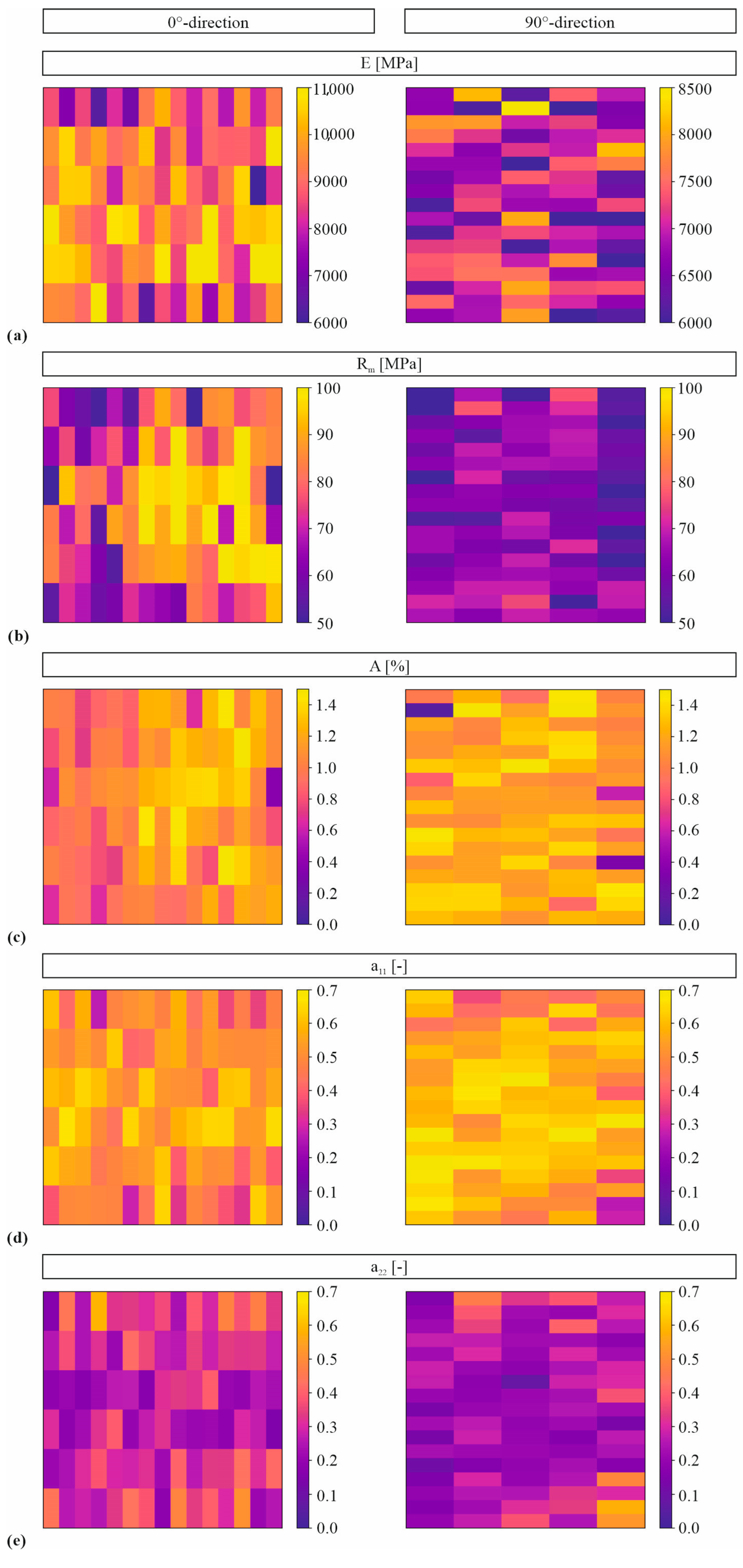
A reason for the fact that a correlation between the fibre orientation and mechanical properties is difficult to identify in the colour plots in
Figure 6 is that the fibre orientation is determined in the head of the specimens, and the mechanical properties are mainly influenced by the microstructure in the gauge section. In
Figure 6d,e, it is clearly visible that the fibre orientation differs significantly between neighbouring specimens. Hence, a strong variation in the fibre orientation is also to be expected across the individual specimens.
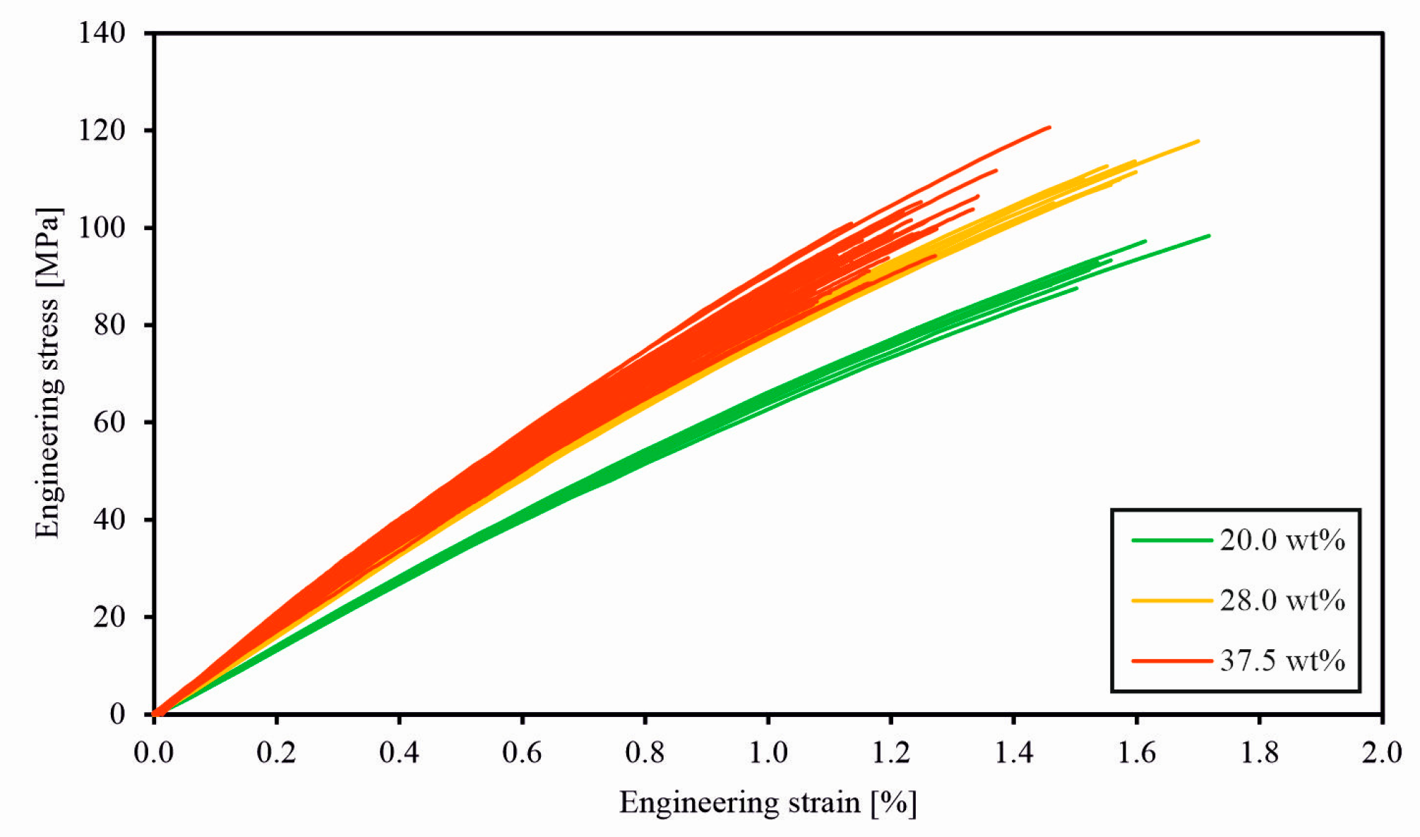
When comparing the stress–strain curves of the tensile tests on specimens with different nominal fibre mass contents, it is important to note that the plates with the highest fibre mass contents were manufactured with a slightly different matrix material formulation. This might be one reason for the significantly higher scatter-band width in the stress–strain curves in
Figure 11 and the values of the Young’s moduli, tensile strength, and failure strain in
Figure 12. However, lower fibre mass contents and thus lower fibre volume contents for geometric reasons imply more freedom for the development of local variability in fibre orientation and maybe even local fibre density, both resulting in a higher variability in the mechanical material properties.
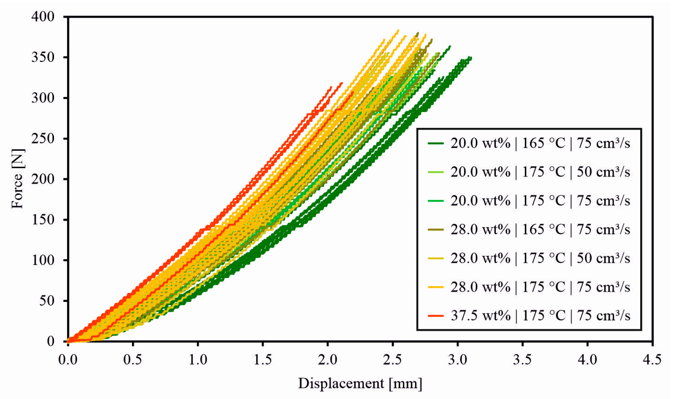
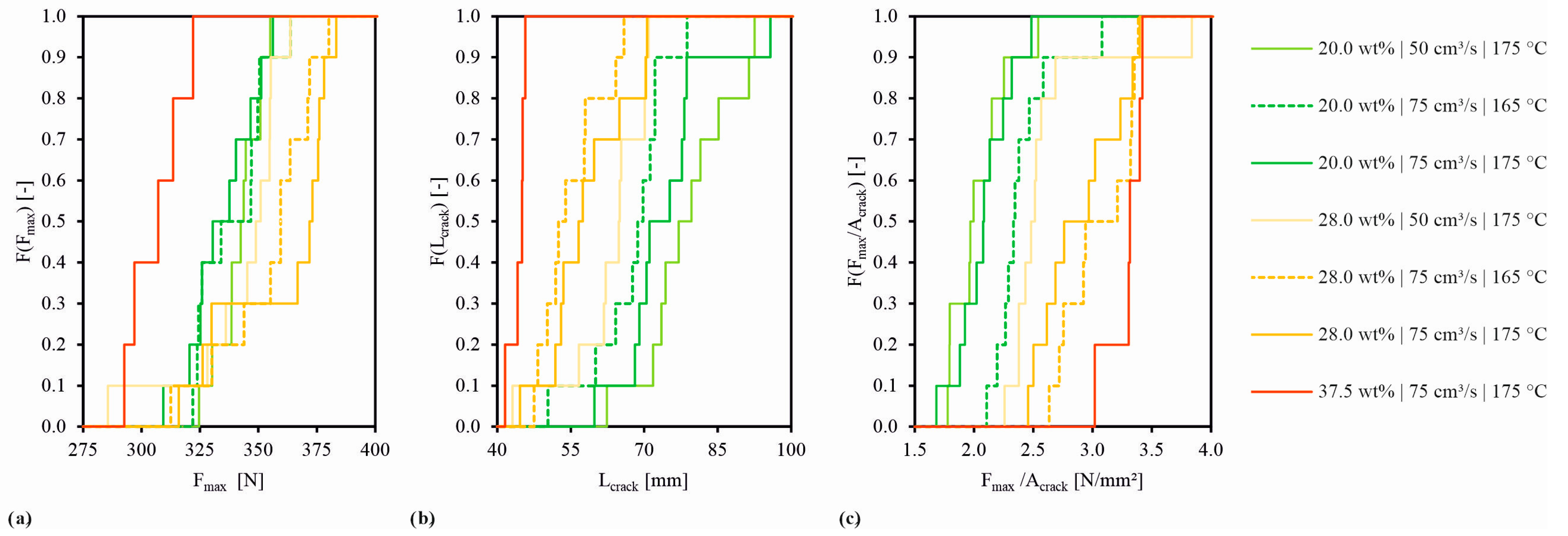
The slightly different matrix material formulation of the plates with a fibre mass content of 37.5 wt% also seems to be the reason for the lower maximum force measured in the breadboard test results in
Figure 13. Nevertheless, it is recognisable that the temperature and injection speed during the manufacturing also have an influence on the material properties (
Figure 14).
5. Conclusions
The present study provides a comprehensive experimental investigation into the influence of the process-related uncertainty on the microstructural characteristics, such as the fibre orientation state, and thus on the uncertainty in the mechanical properties of injection-moulded short fibre composites. For this purpose, macroscopic mechanical experiments on ISO-size tensile, compressive, and shear specimens, extracted at nominally identical positions of several injection-moulded plates, were performed. Furthermore, miniature specimens in the 0° and 90° directions were extracted on regular grids and tested mechanically to identify a correlation between the original spatial position of the specimen within the plate and the local material properties determined on each specimen. The experiments were complemented by tensile experiments on micro specimens with even smaller test sections. In a thorough stochastic approach, the uncertainty in the derived mechanical properties was assessed.
In the experiments on tensile specimens of different sizes, the influence of the test cross-section on the scatter-band position and width for the most relevant material properties was determined. The uncertainty in the material properties strongly depends on the fibre matrix microstructure. In general, more pronounced uncertainties develop for larger fibre volume fractions since the effect of the fibres increases with their volume fraction. Uncertainties due to variations in the manufacturing process are found to be superimposed with basic uncertainties due to strong spatial variations in the local fibre orientation state, even for plates manufactured under nominally identical processing conditions.
The coupon experiments were complemented by breadboard tests on plates, which were manufactured with a variation in the process parameters, such as the input fibre mass content, the processing temperature, and the injection speed. An influence of the manufacturing conditions is clearly observed, however, superimposed with strong basic variabilities in the local fibre orientation state. The superimposed basic variabilities are found to control the uncertainty in the macroscopic material properties to a large extent.
The results allow for a comprehensive assessment of uncertainties to be expected in the material response of short fibre composites due to their uncertain microstructure. It is found that the microstructure, mainly governed by the local fibre orientation distribution, is subject to pronounced uncertain spatial variations. These uncertain spatial variations are superimposed onto the well-known deterministic spatial variations induced by the moulding process, resulting in fibre alignment longitudinal or perpendicular to the flow direction, depending on the distance to the mould surfaces. The superimposed morphological variability is found to result in a pronounced variability in the material response, even in ranges where the processing conditions are similar or even nominally identical. The results reveal a distinct dependence of the uncertainty in the material response on the considered control volume due to self-averaging effects. Hence, the observed material uncertainty needs to be considered, especially in ranges with high local stress gradients, such as loading points, or variations in the structural cross-section, such as notches or at rib roots.
The dominating factors in the material uncertainty are found to be the local fibre orientation distribution, together with the fibre content, which might vary locally in structural applications, especially at notches, sharp corners, and other cross-sectional variations, due to the local flow conditions in the moulding process. Further, however, presumably secondary uncertainties might derive from uncertainties in the process itself, such as variations in the moulding conditions, as well as from uncertainties in the constituent properties.
The resulting experimental and statistically elaborated database serves as a reference database for a probabilistic multiscale and process chain simulation of short fibre-reinforced composites to be published in an upcoming contribution. The experimental study together with the numerical simulations on the one hand allows for a deeper understanding of uncertainties in the structural response of injection-moulded short fibre composites. On the other hand, for the first time, it enables a holistic prediction and assessment of uncertainty propagation from uncertainties in the manufacturing process over uncertainties in the spatial microstructural characteristics up to uncertainties in the material response on the structural level. A profound understanding of the material uncertainties on the structural level might enable a reduction in unnecessarily large safety margins, thereby reducing over-conservatism and enhancing the utilisation of the material.
