Article

Mechanics of Interfacial Debonding in FRP Strengthening Systems: Energy Limits and Characteristic Bond Lengths

Structural Mechanics Laboratory, School of Rural, Surveying and Geoinformatics Engineering, National Technical University of Athens, 9 Iroon Polytechniou Str., Zografou, 15780 Athens, Greece
*
Author to whom correspondence should be addressed.
J. Compos. Sci. 2025, 9(8), 412; https://doi.org/10.3390/jcs9080412
Submission received: 18 June 2025 / Revised: 18 July 2025 / Accepted: 23 July 2025 / Published: 4 August 2025
(This article belongs to the Special Issue Polymer Composites and Fibers, 3rd Edition)

Abstract

This study examines the energy behavior of a strengthening system consisting of a Fiber Reinforced Polymer (FRP) plate bonded to a rigid substrate and subjected to tensile loading, where the adhesive interface is governed by a bilinear bond–slip law with a vertical descending branch. The investigation focuses on the interaction between the elastic energy stored in the FRP and the adhesive interface, as well as the characteristic lengths that control the debonding process. Analytical expressions for the strain energy stored in both the FRP plate and the adhesive interface are derived, enabling the identification and evaluation of two critical characteristic lengths as the bond stress at the loaded end approaches its maximum value l c , at which the elastic energies of the FRP and the adhesive interface converge, signaling energy saturation; and l m a x , where the adhesive interface attains its peak energy absorption. Upon reaching the energy saturation state, the system undergoes failure through the sudden and complete debonding of the FRP from the substrate. The onset of unstable debonding is rigorously analyzed in terms of the first and second derivatives of the total potential energy with respect to the bond length. It is further demonstrated that abrupt debonding may also occur in cases where the length exceeds l c when the bond stress reaches its maximum, and the bond–slip law is characterized by a vertical branch. The findings provide significant insights into the energy balance and stability criteria governing the debonding failure mode in FRP-strengthened structures, highlighting the pivotal role of characteristic lengths in predicting both structural performance and failure mechanisms.

1. Introduction

The use of Fiber Reinforced Polymer (FRP) composites has witnessed a significant surge in civil engineering applications over the past few decades. Their compelling attributes, including a high strength-to-weight ratio, inherent corrosion resistance, and ease of installation, have positioned FRPs as a viable and often superior alternative to traditional materials such as steel, particularly in the strengthening and rehabilitation of existing structures [1,2,3]. Nonetheless, recent long-term studies indicate that the durability of FRP—especially GFRP—may be compromised under sustained load and aggressive environments, even when embedded in concrete [4,5].
From enhancing the flexural and shear capacity of beams and slabs to providing confinement for columns and retrofitting seismically vulnerable elements, FRP composites offer practical and effective solutions for extending the service life and improving the performance of a wide range of infrastructure systems [6,7,8,9,10].
Despite the widespread adoption and demonstrated efficacy of FRP strengthening techniques, the durability and long-term performance of these systems are intrinsically linked to the integrity of the bond interface between the FRP plate and the substrate material. Debonding, the premature separation of the FRP from the substrate, remains a critical failure mode that can compromise the intended strengthening effects and, in severe cases, lead to structural collapse. This phenomenon is complex and influenced by a multitude of factors, including the properties of the adhesive, the surface preparation of the substrate, the applied loading conditions, environmental exposure, and the geometry of the bonded joint [11,12,13,14].
To reliably design and implement FRP strengthening solutions that are both durable and effective, a fundamental understanding of the mechanics governing bond behavior and debonding mechanisms is essential. This requires a thorough investigation of stress transfer mechanisms at the interface and the energy principles underlying debonding initiation and propagation [15,16,17,18,19,20,21,22,23,24,25]. Earlier investigations [26,27,28,29,30,31] approached FRP debonding through fracture-mechanics energy-release-rate criteria, in which failure is triggered when the rate of change in the system’s total (or elastic) energy—associated with the growth of a pre-existing crack—reaches a material-dependent critical value. In the present study, a different viewpoint is adopted: the elastic energy is decomposed into two spatially distributed “reservoirs”, one in the FRP plate and one in the adhesive interface. Failure is shown to occur when the system attains an energy-saturation state, i.e., when the elastic energy stored in the FRP equals that stored in the interface and the bond stress at the loaded end reaches its maximum. The critical bond length at which this equilibrium is achieved coincides with the development length reported experimentally, providing a new, directly computable design parameter. Furthermore, characteristic lengths are critical for understanding FRP-bonded system behavior. These lengths, intrinsic to the system’s material and geometric properties, govern interfacial stress development, strain distribution within the FRP, and overall load transfer efficiency [32,33,34,35]. Determining these characteristic lengths provides valuable insights into the effective bond length needed for optimal performance. In addition to mechanics-based analytical and numerical formulations, data-driven approaches have recently gained traction [36,37]. These approaches offer high predictive accuracy but provide limited physical insight, underscoring the complementary role of the mechanics-based framework developed in the present work. The model developed herein is confined to short-term loading scenarios in which visco-elastic creep, fatigue damage, and environmental aging of the FRP–adhesive system are negligible. The extension of the framework to sustained or cyclic loads will require time-dependent constitutive laws and will be addressed in future work.
In this study, the energy behavior of an FRP plate bonded to a rigid substrate and subjected to tensile loading is investigated. Analytical formulations for the strain energy stored in both the FRP plate and the adhesive interface are employed to clarify the relationship between the applied load, bond length, and stored elastic energy. Two key characteristic lengths are introduced and analyzed: l c , which represents the effective stress transfer development along the bond, and l m a x , corresponding to the maximum strain energy within the adhesive interface. The significance of these characteristic lengths for energy storage and their potential in predicting debonding onset is assessed through numerical evaluation using representative material parameters. The implications of the findings for interface stability and practical design considerations in FRP strengthening applications are discussed. These insights are shown to advance the fundamental understanding of FRP-bonded system mechanics and to support more reliable strengthening designs.

2. The Strengthening System and Its Elastic State

In this section, the elastic state of the structural system depicted in Figure 1 is analyzed, and then its elastic stability is investigated. The system consists of an FRP plate adhered to a rigid substrate using an adhesive material. The bond length of the FRP plate is denoted by l , and its width and thickness by b and t , respectively.
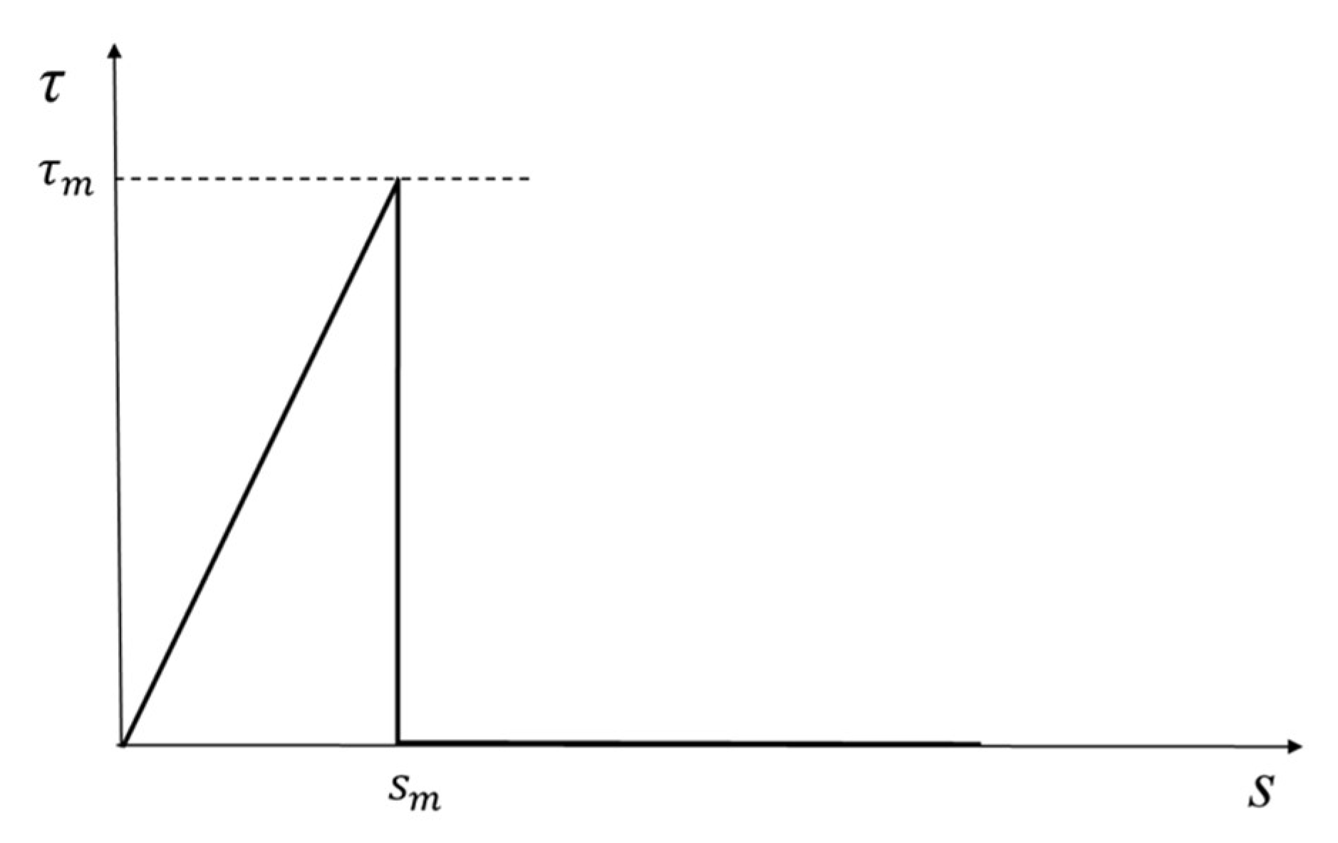
The FRP plate exhibits linear elastic behavior up to fracture, with an elastic modulus E and tensile strength f u . The adhesive material is modeled as continuously distributed shear springs of negligible thickness along the interface. The mechanical behavior of the springs is described by the τ s diagram shown in Figure 2, where s denotes the spring extension and τ the corresponding shear stress.
The spring stress ( τ ) represents the interfacial bond stress, while the spring extension ( s ) corresponds to the relative slip between the FRP and substrate. Since the substrate is rigid, the slip s coincides with the longitudinal displacement of the FRP plate. The τ s diagram consists of an ascending linear branch followed by a vertical descending branch, with the peak bond stress τ m and its corresponding slip s m defining the transition point. The equation of the ascending branch is given by   τ = τ m s / s m   ( s s m ) . When s > s m , τ = 0 , indicating bond failure and crack formation. The FRP plate can be subjected to uniform stresses at its end cross-sections and can sustain interfacial shear stresses   τ distributed uniformly along its width. Under these assumptions, the problem reduces to a one-dimensional analysis along the   x -axis, which coincides with the FRP plate’s longitudinal axis. The origin x = 0 is placed at the centroid of the right-end cross-section (Figure 1).
In what follows, the elastic state of the system resulting from an external tension applied at the right end of the plate is analyzed (Figure 1). The external tension progresses from zero and increases monotonically until reaching its final value σ 0 . At any cross-section of the FRP plate located at position x  ( l x 0 ) , the displacement and normal stress are denoted by u ( x ) and σ ( x ) , respectively, with σ ( x ) = E u ( x ) . Since the substrate is rigid and fixed, the spring extension coincides with the FRP plate displacement ( s ( x ) = u ( x ) ) ; hereafter, the slip function s ( x ) is used to describe both the plate displacement and spring extension.
Below, the related boundary value problem of the stressed system described above is solved for the case in which s s m . The governing differential equation of the boundary value problem is given by
d 2 s d x 2 = λ 2 s , λ 2 = 1 E t τ m s m
The above equation is derived by considering equilibrium of an infinitesimal FRP element using its free-body diagram. The differential Equation (1) is solved in the domain l x 0 for the following boundary conditions at the FRP plate ends:
E d s d x x = l = 0 ,   E d s d x x = 0 = σ 0
This boundary value problem is solved using standard procedures, yielding
s ( x ) = σ 0 λ E cosh λ l + λ x sinh ( λ l )
Based on Equation (3) and using the τ = τ m s / s m , σ = E d s / d x , the following is obtained:
σ ( x ) = σ 0 sinh ( λ l + λ x ) sinh ( λ l ) , τ ( x ) = σ 0 λ t cosh λ l + λ x sinh ( λ l )
Equations (3) and (4) define the system’s elastic field and will subsequently be employed to examine its energy state.

3. The Energy State of the System and the Characteristic Lengths

Having determined the elastic field of the system, the strain energies stored in the FRP plate and the adhesive interface, denoted by U p and U s , respectively, can be calculated using the following expressions
U p = l 0 ( 0 ε ( x ) σ d ε ) b t d x , U s = l 0 [ 0 s ( x ) τ ( s ) d s ] b d x
where
0 ε ( x ) σ d ε = 1 2 E σ 2 , 0 s ( x ) τ ( s ) d s = τ m 2 s m s 2 ( x )
are the energy densities in the FRP plate volume and bonded interface area, respectively, with ε ( x ) = u ( x ) . Using Equations (3) and (4), Equations (5) and (6) provide
U p = σ 0 2 b t 4 E 1 λ tanh ( λ l ) l [ 1 tanh 2 ( λ l ) ]
U s = σ 0 2 b t 4 E 1 λ tanh ( λ l ) + l [ 1 tanh 2 ( λ l ) ]
From Equation (3), the displacement at the loaded end ( x = 0 ) of the FRP plate is
s ( 0 ) = σ 0 λ E 1 tanh ( λ l )
which must satisfy s ( 0 ) < s m . The work performed by the external force   b t σ 0 applied to the system is
W e x t = 1 2 s ( 0 ) σ 0 b t = σ 0 2 b t 2 E 1 λ tanh ( λ l )
As expected, W e x t = U p + U s (energy balance). Since tan h ( λ l ) < 1 , Equations (7) and (8) suggest that U p < U s . This means that the change in the system’s internal energy caused by the external load is distributed unevenly between the two components, with the adhesive interface absorbing the larger portion. The energy absorbed by the adhesive interface reaches its maximum when the external stress σ 0 drives the displacement of the loaded end to the value s m , which corresponds to the slip at maximum bond stress. If this value of external stress is denoted by σ 0 , m , then
σ 0 , m = λ E s m tanh ( λ l )
For this value of the external stress, the energies stored in the FRP plate and adhesive interface denoted by U p , m   and U s , m respectively, are
U p , m = 1 2 G c b λ tanh 2 ( λ l ) 1 tanh ( λ l ) λ l [ 1 tanh 2 ( λ l ) ]
U s , m = 1 2 G c b λ tanh 2 ( λ l ) 1 tanh ( λ l ) + λ l [ 1 tanh 2 ( λ l ) ]
where
G c = τ m s m 2
represents the interfacial debonding energy, defined as the energy required per unit area to achieve the complete separation of the FRP plate from the substrate. For the linear elastic bond–slip law with an abrupt (vertical) drop after the peak bond stress shown in Figure 2, this quantity corresponds to the area under the bond–slip curve up to the maximum slip.
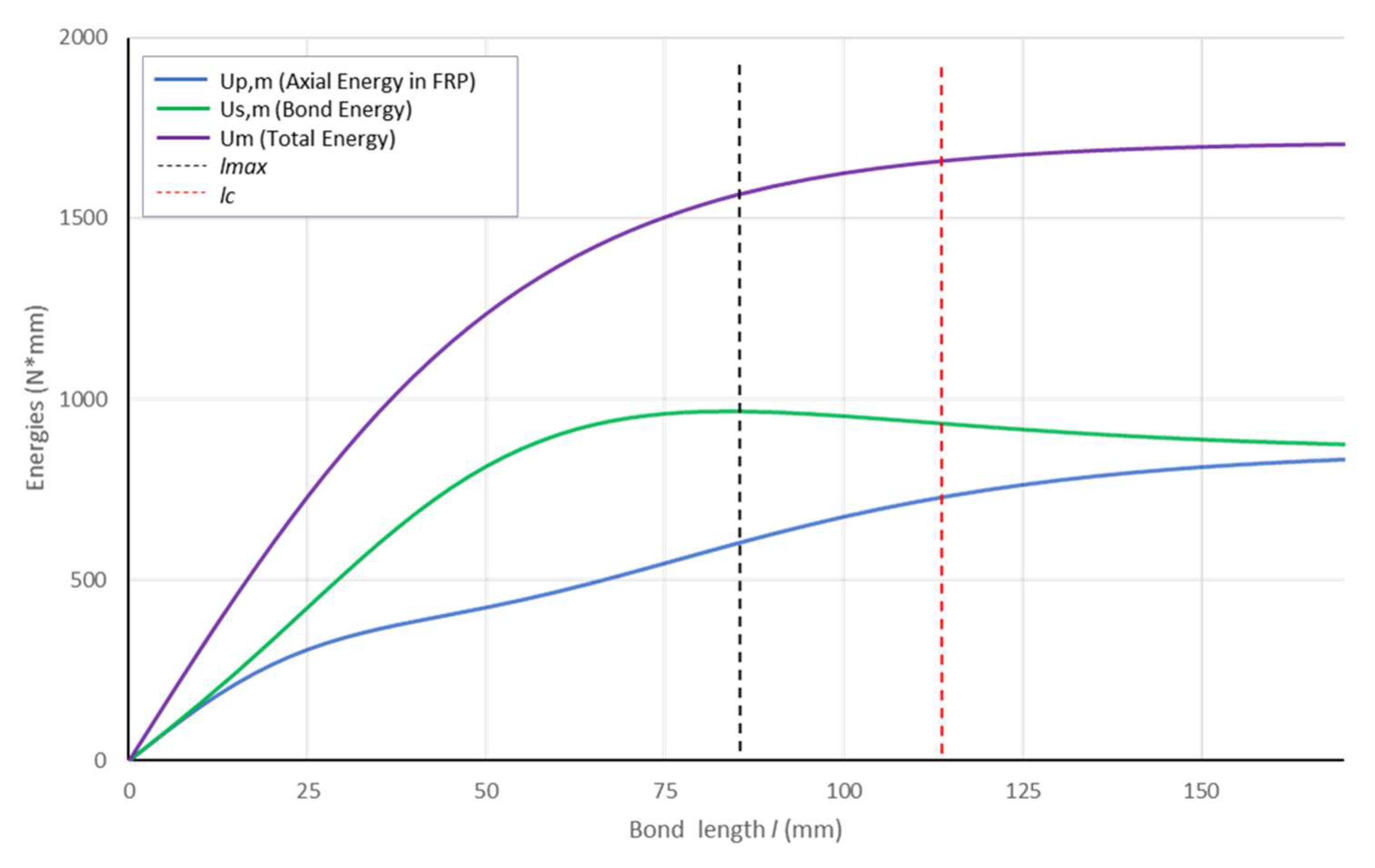
Next, the variations in the energies U p , m   a n d   U s , m   will be examined as the bond length l increases from zero to large values with the displacement at the loaded end remaining s m . Figure 3 illustrates the graphs of U p , m and U s , m , given by Equations (12) and (13), along with the total energy U m ( = U p , m + U s , m ) accumulated in the system, plotted as a function of the bond length   l . The curves in the diagram have been calculated for E = 200.000   MPa , t = 0.3   mm , b = 50   mm , τ m = 5   MPa and s m = 0.25   mm .
The function plots reveal that for large values of the bond length, the energies stored in the two components of the system asymptotically tend to equalize at a specific limiting value U .
The strain energy stored in the FRP increases monotonically and tends toward this value, while the energy stored at the interface approaches the same value after passing through an absolute maximum. The limiting value of the energies for the two components as the bond length tends to infinity is
U = lim l U p , m = lim l U s , m = 1 2 lim l U m = 1 2 G c b λ
To provide a practical approximation, a characteristic l c   is selected as a sufficiently large bond length at which the two energies effectively equalize. Assuming tan h ( λ l c ) = 0.97 , this leads to
l c = 2.09 / λ
then U = 0.239 b G c l c . The absolute maximum of the energy stored at the interface is found by setting the first derivative of the function U s , m equal to zero, which leads to the following algebraic equation
1 + T 2 + 2 λ l T ( 1 2 T 2 ) = 0
with T = tan h ( λ l ) . This equation is solved graphically, determining the length
l max = 1.529 / λ
Theoretical and numerical investigation of the strain energy functions U p , m   and U s , m   reveals that the energy behavior of the system is governed by two characteristic lengths: l c , at which the elastic energies stored in the two components of the system become approximately equal, and l m a x , at which the energy stored in the adhesive interface reaches its maximum value. As the system approaches the critical length l c , while maintaining the slip at the loaded end equal to s m , the portion of the total energy accommodated by the interface gradually decreases, whereas the portion absorbed by the FRP plate steadily increases. This process reflects the evolving manner in which the system handles the incoming energy as the bond length increases. The length l c marks the strain energy saturation point of the system—the state at which its capacity to accommodate additional energy becomes critically limited. Beyond this point, the system is no longer able to accept further energy input without undergoing a qualitative change in its internal balance. This limitation in energy accommodation signals a transition: the system begins to seek alternative mechanical responses or failure modes to cope with the energetic overload.
As the bond length reaches the characteristic length, l m a x , the bond mechanism becomes saturated and cannot store additional energy effectively. When l > l m a x , the strain energy stored in the interface decreases, while that stored in the FRP plate continues to increase. This reflects a transition where the FRP plate begins to carry a greater portion of the applied energy as the bond’s capacity diminishes. The total energy   U m   increases monotonically with l , indicating that the system continues to accumulate energy even after the bond energy peaks, primarily through deformation of the FRP.
The evolution of the energy components highlights the efficiency of the bond at small lengths and the increasing role of the FRP at larger bond lengths. Understanding this distribution is critical for optimizing bond length in FRP strengthening applications to ensure both effective energy absorption and load transfer. It is noted that when l l m a x , then U s , m ( l m a x ) 0.327 G c b l c , where for the latter the relation l m a x = 0.731 l c was used.

4. Energy-Based Interpretation of the Sudden Debonding of the FRP Plate

At the critical condition where the bonding length reaches l = l c and the slip at the loaded end attains its maximum value s m , the system exhibits a unique energy state. At this point, the elastic energies stored in the bond interface and the FRP plate become approximately equal. This energy balance reflects a saturated state in which neither the bond nor the FRP can accommodate further energy input without a change in the deformation mechanism. As the external force slightly exceeds the critical value σ c = σ 0 , m ( l c ) additional work is imposed on the system. However, both the bond and the FRP have exhausted their capacity to store more energy: the bond stress has reached its maximum τ m along nearly the entire bond length, and the FRP strain cannot increase without inducing incompatible displacements. Consequently, no further redistribution of energy between the two mechanisms is possible. This leads to a sudden loss of equilibrium, resulting in the rapid propagation of debonding. The phenomenon is energetically inevitable, as the system cannot transition smoothly to a new equilibrium state once the available mechanisms for energy storage have been saturated.
Since the failure of the system manifests itself as a loss of equilibrium at a critical bonding length, combined with a limiting deformation state, it is of particular interest to investigate the behavior of the total potential energy at the critical debonding condition, considering it as a function of the bonding length l . The total potential energy Π m   of the system is defined as
Π m = U p , m + U s , m + Ω m
where   U p , m and   U s , m are given by (12) and (13), and Ω m is the potential energy of the external force σ 0 , m b t
Ω m = σ 0 , m b t s m = b t σ 0 , m 2 E λ 1 tanh ( λ l )
Substituting Equations (12), (13), and (20) into Equation (19), the following obtained
Π m = 1 2 b t σ 0 , m 2 E λ 1 tanh ( λ l )
Regarding the parameter l , the first and second variations in the total potential energy are determined as
δ Π m = 1 2 b t σ 0 , m 2 E 1 tanh 2 ( λ l ) [ 1 + tanh ( λ l ) ] [ 1 tanh ( λ l ) ] δ l
δ 2 Π m = 1 2 b t σ 0 , m 2 E λ tanh 3 ( λ l ) [ 1 + tanh ( λ l ) ] [ 1 tanh ( λ l ) ] δ l δ l
By considering large values λ l and setting 0.97 tan h λ l instead of 1 tan h λ l , the above expressions will be replaced by their approximate forms as follows:
δ Π 1 2 b t σ 0 , m 2 E 1 tanh 2 ( λ l ) [ 1 + tanh ( λ l ) ] [ 0.97 tanh ( λ l ) ] δ l
δ 2 Π m 1 2 b t σ 0 , m 2 E λ tanh 3 ( λ l ) [ 1 + tanh ( λ l ) ] [ 0.97 tanh ( λ l ) ] δ l δ l
The above relations show that both variations vanish when tan h λ l = 0.97 ; the latter occurs, when
l = l c 2 / λ = 2 E t s m τ m
In addition, the following is valid:
if   l < l c ,   then   δ 2 Π m < 0
if   l > l c ,   then   δ 2 Π m > 0
The above relations reveal that when l = l c , the system passes from a stable equilibrium state, corresponding to δ 2 Π m > 0 , to an unstable one, corresponding to δ 2 Π m < 0 . In other words, when the FRP plate is loaded by an external tension σ 0 , as in Figure 1, and the slip of the loaded end has reached the value s m , then, the equilibrium state of the system becomes unstable as the bond length l approaches the value l c . The external stress resulting from the instability of the system is denoted by σ 0 , c r and has the following value:
σ 0 , c r = 0.97 E λ s m = 0.97 E τ m s m t
The aforementioned results align with the fundamental energy principles governing the equilibrium of mechanical systems, despite the absence of an explicit variation in elastic displacement parameters within the analysis. However, such a variation appears to occur indirectly through changes in the volume of the FRP plate, resulting from the variation in the bond length. This observation highlights an interesting aspect that warrants further investigation.
Let us now assume that the bonding length is l > l c and that the system is subjected to an external stress σ 0 . At this state, the elastic energies stored in the two components of the system are given by Equations (7) and (8). If the external stress increases to the value σ 0 , m = λ E s m tan h ( λ l ) , the slip at the loaded end reaches at limiting value s m . Since the bonding length exceeds the critical value, l > l c , and the slip–bond relationship follows the behavior shown in Figure 2, a fundamental question arises: what will happen, and why, if the external stress exceeds the value σ 0 , m ?
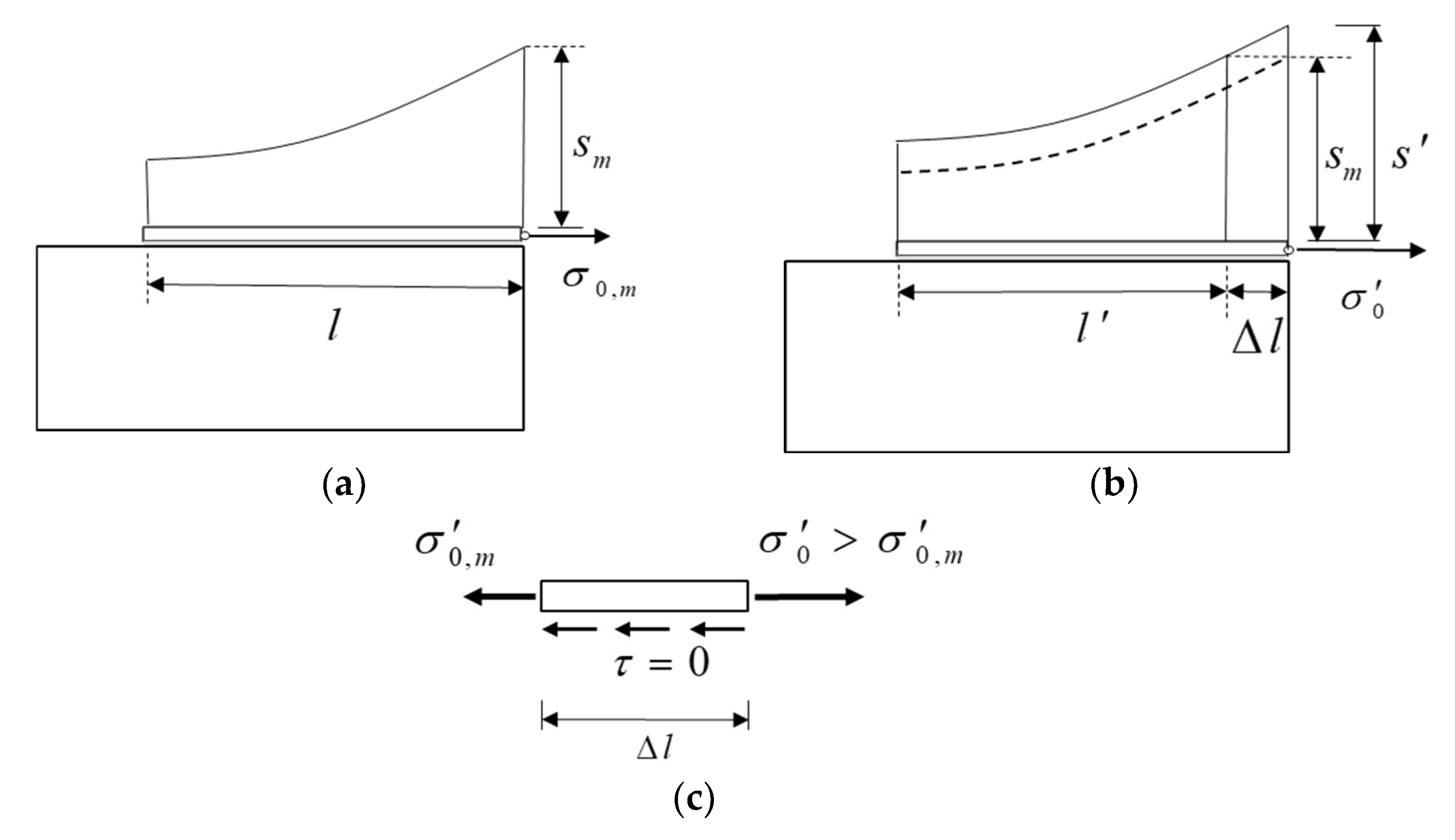
If the external stress exceeds σ 0 , m , reaching a value σ 0 , as shown in Figure 4, the slip at the loaded end of the FRP plate increases to s .
As a result, an additional amount of energy—equal to the extra work exerted by the external force—must be absorbed by the system. According to Equation (13), accommodating this additional energy requires the system to reduce the bonding length to l , thereby increasing the interface energy and absorbing a portion of the input. The remaining energy is stored in the FRP plate. With the new bond length l , the system exhibits the slip s m   at the right end of the bonded zone, corresponding to a normal stress σ 0 , m = λ E s m tan h λ l ( < σ 0 , m ) . It should be noted that along the debonded length l l of the plate, where complete debonding has occurred following the slip–bond law, no interfacial bond forces are available to balance the forces σ 0 b t and σ 0 , m b t acting on the two cross-sections of the debonded portion. As a result, the bonded segment can only sustain the force σ 0 , m b t and cannot carry the additional increment Δ F = ( σ 0 σ 0 , m ) b t . This weakness could only be overcome if the descending branch of the slip–bond law did not drop vertically, thus providing residual bonding capacity within the debonded segment. In the absence of such a residual bond, system equilibrium is lost, leading to a sudden and rapid propagation of debonding. The system’s energy response under a slip–bond law featuring a descending branch with a non-vertical slope is an interesting issue and will be examined in detail in a forthcoming publication.

5. Conclusions

This study has presented a closed-form, energy-based explanation of the sudden debonding of an FRP plate bonded to a rigid substrate and loaded in tension, assuming a bilinear bond–slip law with a vertical descending branch. Analytical expressions were obtained for the strain energy stored in both the FRP plate and the adhesive interface, enabling the spatial transfer of energy along the bond line to be quantified explicitly. Two characteristic lengths emerge from the analysis. The first, denoted l c , is reached when the elastic energy in the FRP becomes equal to the elastic energy in the adhesive interface and, simultaneously, the bond stress at the loaded end attains its peak value; this combined condition defines an energy-saturation state. The second length, l m a x , corresponds to the point at which the interface stores its maximum possible energy under continued bonding. Once energy saturation is reached at l c the system loses stability and debonding proceeds explosively; for bonds longer than l c the same unstable outcome arises as soon as the peak bond stress is reached under the assumed vertical softening branch.
A rigorous examination of the first and second derivatives of the total potential energy confirmed the transition from stable to unstable behavior, providing a precise criterion for catastrophic debonding. The theoretically predicted l c coincides with the development length widely reported in experimental studies based on maximum transferable load, underscoring the compatibility of the present closed-form model with existing evidence. Because l c and   l m a x can be evaluated analytically, they offer a straightforward means of estimating the minimum anchorage length and of performing rapid stability checks in practical FRP-strengthening designs.
The framework developed here is confined to linear-elastic behavior and therefore omits the progressive softening and time-dependent effects that may occur in service. The influence of a graded softening branch, together with creep and fatigue, is the subject of a companion study that will combine cohesive-zone numerical simulations with targeted bond tests to furnish direct validation and extend the applicability of the proposed model.

Author Contributions

Conceptualization, M.K.; methodology, N.M. and M.K.; software, N.M.; validation, N.M. and M.K.; formal analysis, N.M. and M.K.; investigation, N.M. and M.K.; writing—original draft preparation, M.K.; writing—review and editing, N.M.; visualization, N.M. and M.K.; supervision, M.K.; project administration, M.K. All authors have read and agreed to the published version of the manuscript.

Funding

This research received no external funding.

Data Availability Statement

The data presented in this study are available on request from the corresponding author.

Acknowledgments

During the preparation of this manuscript, the authors used the AI-based language model ChatGPT (OpenAI) for assistance with language editing and for generating the graphical representation of an algebraic expression based on equations and parameters provided by the authors. All outputs were critically reviewed, edited, and validated by the authors, who take full responsibility for the final content.

Conflicts of Interest

The authors declare no conflict of interest.

References

  1. American Concrete Institute. Guide for the Design and Construction of Externally Bonded FRP Systems for Strengthening Concrete Structures; ACI 440.2R-17; American Concrete Institute: Farmington Hills, MI, USA, 2017. [Google Scholar]
  2. ISIS Canada. Design Manual No. 3: Reinforcing Concrete Structures with Fibre Reinforced Polymers; ISIS: Winnipeg, MB, Canada, 2007. [Google Scholar]
  3. ISIS Canada. Design Manual No. 4: Strengthening Concrete Structures with Externally Bonded Fibre Reinforced Polymers; ISIS: Winnipeg, MB, Canada, 2007. [Google Scholar]
  4. Zhou, J.K.; Hao, Z.-H.; Zeng, J.J.; Feng, S.-Z.; Liang, Q.J.; Zhao, B.; Feng, R.; Zhuge, Y. Durability assessment of GFRP bars embedded in UHP-ECCs subjected to an accelerated aging environment with sustained loading. Constr. Build. Mater. 2024, 419, 135364. [Google Scholar] [CrossRef]
  5. Zeng, J.J.; Hao, Z.-H.; Liang, Q.J.; Zhuge, Y.; Liu, Y. Durability assessment of GFRP bars exposed to combined accelerated aging in alkaline solution and a constant load. Eng. Struct. 2023, 297, 116990. [Google Scholar] [CrossRef]
  6. Saadatmanesh, H.; Ehsani, M.R. RC beams strengthened with FRP plates. I: Experimental study. J. Struct. Eng. 1991, 117, 3417–3433. [Google Scholar]
  7. Saadatmanesh, H.; Ehsani, M.R. RC beams strengthened with FRP plates. II: Analysis and parametric study. J. Struct. Eng. 1991, 117, 3434–3455. [Google Scholar] [CrossRef]
  8. Khalifa, A.; Gold, W.J.; Nanni, A.; Abdel Aziz, M.I. Contribution of externally bonded FRP to shear capacity of RC flexural members. J. Compos. Constr. 1998, 2, 195–202. [Google Scholar] [CrossRef]
  9. Chaallal, O.; Shahawy, M. Performance of fiber-reinforced polymer-wrapped reinforced concrete column under combined axial-flexural. ACI Struct. J. 2000, 97, 659–668. [Google Scholar]
  10. Malek, A.M.; Saadatmanesh, H.; Ehsani, M.R. Prediction of failure load of R/C beams strengthened with FRP plate due to stress concentration at the plate end. ACI Struct. J. 1998, 95, 142–152. [Google Scholar] [CrossRef]
  11. Aidoo, J.; Harris, K.; Petrou, M. Fatigue behavior of carbon fiber reinforced polymer-strengthened concrete bridge girders. J. Compos. Constr. 2004, 8, 501–509. [Google Scholar] [CrossRef]
  12. De Lorenzis, L.; Miller, B.; Nanni, A. Bond of FRP laminates to concrete. ACI Mater. J. 2001, 98, 256–264. [Google Scholar]
  13. Al-Rousan, R.Z.; Al-Tahat, M.F. Consequence of surface preparation techniques on the bond behavior between concrete and CFRP composites. Constr. Build. Mater. 2019, 212, 362–374. [Google Scholar] [CrossRef]
  14. Shi, J.W.; Cao, W.H.; Wu, Z.S. Effect of adhesive properties on the bond behaviour of externally bonded FRP-to-concrete joints. Compos. Part B Eng. 2019, 177, 107365. [Google Scholar] [CrossRef]
  15. Chen, J.F.; Yuan, H.; Teng, J.G. Debonding failure along a softening FRP-to-concrete interface between two adjacent cracks in concrete members. Eng. Struct. 2007, 29, 259–270. [Google Scholar] [CrossRef]
  16. Zhang, P.; Lei, D.; Ren, Q.; He, J.; Shen, H.; Yang, Z. Experimental and numerical investigation of debonding process of the FRP plate-concrete interface. Constr. Build. Mater. 2020, 235, 117457. [Google Scholar] [CrossRef]
  17. Yao, J.; Teng, J.G.; Chen, J.F. Experimental study on FRP-to-concrete bonded joints. Compos. Part B Eng. 2005, 36, 99–113. [Google Scholar] [CrossRef]
  18. Wu, Y.F.; Jiang, C. Quantification of bond-slip relationship for externally bonded FRP-to-concrete joints. J. Compos. Constr. 2013, 17, 673–686. [Google Scholar] [CrossRef]
  19. Lu, X.Z.; Teng, J.G.; Ye, L.P.; Jiang, J.J. Bond–slip models for FRP sheets/plates bonded to concrete. Eng. Struct. 2005, 27, 920–937. [Google Scholar] [CrossRef]
  20. Biscaia, H.C.; Chastre, C.; Silva, M.A.G. Linear and nonlinear analysis of bond-slip models for interfaces between FRP composites and concrete. Compos. Part B Eng. 2013, 45, 1554–1568. [Google Scholar] [CrossRef]
  21. Pan, J.; Wu, Y.F. Analytical modeling of bond behavior between FRP plate and concrete. Compos. Part B Eng. 2014, 61, 17–25. [Google Scholar] [CrossRef]
  22. Wang, J. Debonding of FRP-plated reinforced concrete beam, a bond-slip analysis. I. Theoretical formulation. Int. J. Solids Struct. 2006, 43, 6649–6664. [Google Scholar] [CrossRef]
  23. Ascione, F.; Napoli, A.; Realfonzo, R. Interface bond between FRP systems and substrate: Analytical modeling. Compos. Struct. 2021, 257, 112942. [Google Scholar] [CrossRef]
  24. Calabrese, S.A.; Colombi, P.; D’Antino, T. Analytical solution of the bond behavior of FRCM composites using a rigid-softening cohesive material law. Compos. Part B Eng. 2019, 174, 107051. [Google Scholar] [CrossRef]
  25. Ferracuti, B.; Savoia, M.; Mazzotti, C. Interface law for FRP–concrete delamination. Compos. Struct. 2007, 80, 523–533. [Google Scholar] [CrossRef]
  26. Täljsten, B. Strengthening of concrete prisms using the plate-bonding technique. Int. J. Fract. 1996, 82, 253–266. [Google Scholar] [CrossRef]
  27. Achintha, P.M.M.; Burgoyne, C.J. Fracture mechanics of plate debonding. J. Compos. Constr. 2008, 12, 396–404. [Google Scholar] [CrossRef]
  28. Leung, C.K.Y.; Yang, Y. Energy-based modeling approach for debonding of FRP plate from concrete substrate. J. Eng. Mech. 2006, 132, 583–593. [Google Scholar] [CrossRef]
  29. Carpinteri, A.; Cornetti, P.; Pugno, N. Edge debonding in FRP strengthened beams: Stress versus energy failure criteria. Eng. Struct. 2009, 31, 2436–2447. [Google Scholar] [CrossRef]
  30. Gunes, O.; Buyukozturk, O.; Karaca, E. A fracture-based model for FRP debonding in strengthened beams. Eng. Fract. Mech. 2009, 76, 1897–1909. [Google Scholar] [CrossRef]
  31. Arduini, M.; Di Tommaso, A.; Nanni, A. Brittle failure in FRP plate and sheet bonded beams. ACI Struct. J. 1997, 94, 363–370. [Google Scholar] [CrossRef] [PubMed]
  32. Diab, H.M.; Farghal, O.A. Bond strength and effective bond length of FRP sheets/plates bonded to concrete considering the type of adhesive layer. Compos. Part B Eng. 2014, 58, 618–624. [Google Scholar] [CrossRef]
  33. Atunbi, E.O.; Lloyd, A.; Bischoff, P.H. Effective bond length of CFRP sheets externally bonded to reinforced concrete. Build. Tomorrow’s Soc. 2018, 167, 726–738. [Google Scholar]
  34. Ueda, T.; Dai, J. Interface bond between FRP sheets and concrete substrates: Properties, numerical modeling and roles in member behaviour. Prog. Struct. Eng. Mater. 2005, 7, 27–43. [Google Scholar] [CrossRef]
  35. Hosseini, A.; Mostofinejad, D. Effective bond length of FRP-to-concrete adhesively-bonded joints: Experimental evaluation of existing models. Int. J. Adhes. Adhes. 2014, 48, 150–158. [Google Scholar] [CrossRef]
  36. Machello, C.; Rahmati, M.; Bazli, M.; Rajabipour, A.; Arashpour, M.; Hassanli, R.; Shakiba, M. Machine learning-based prediction of bond performance of FRP composite bars in concrete for marine composite structures. Compos. Struct. 2025, 370, 119401. [Google Scholar] [CrossRef]
  37. Zhang, P.F.; Zhang, D.; Zhao, X.L.; Zhao, X.; Iqbal, M.; Tuerxunmaimaiti, Y.; Zhao, Q. Natural language processing-based deep transfer learning model across diverse tabular datasets for bond strength prediction of composite bars in concrete. Comput.-Aided Civ. Infrastruct. Eng. 2025, 40, 917–939. [Google Scholar] [CrossRef]
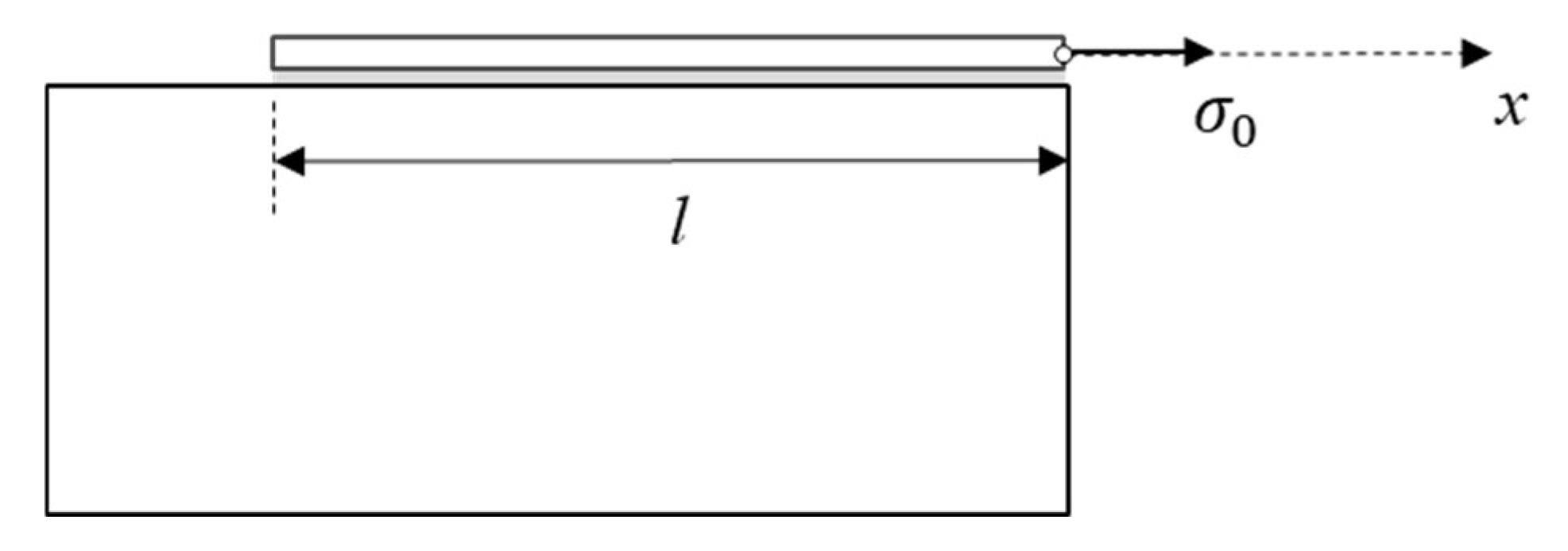
Figure 1. The FRP plate bonded to a rigid concrete substrate.
Jcs 09 00412 g001
Figure 2. The slip–bond diagram with a sudden stress drop.
Jcs 09 00412 g002
Figure 3. Variations in the strain energies as a function of the bond length.
Jcs 09 00412 g003
Figure 4. The figures (a,b) show the slip along the bond length for the external stresses σ 0 , m   and σ 0 , respectively, and (c) shows the free body diagram of the debonded part of the FRP plate.
Jcs 09 00412 g004
Disclaimer/Publisher’s Note: The statements, opinions and data contained in all publications are solely those of the individual author(s) and contributor(s) and not of MDPI and/or the editor(s). MDPI and/or the editor(s) disclaim responsibility for any injury to people or property resulting from any ideas, methods, instructions or products referred to in the content.