Article

Material Removal in Mycelium-Bonded Composites Through Laser Processing

by
Maciej Sydor
1,*,
Grzegorz Pinkowski
2 and
Agata Bonenberg
3
1
Institute of Safety and Quality Engineering, Faculty of Engineering Management, Poznań University of Technology, 60-965 Poznań, Poland
2
Department of Woodworking and Fundamentals of Machine Design, Faculty of Forestry and Wood Technology, Poznań University of Life Sciences, 60-637 Poznań, Poland
3
Institute of Interior Design and Industrial Design, Faculty of Architecture, Poznan University of Technology, 61-131 Poznań, Poland
*
Author to whom correspondence should be addressed.
J. Compos. Sci. 2025, 9(8), 389; https://doi.org/10.3390/jcs9080389
Submission received: 25 June 2025 / Revised: 18 July 2025 / Accepted: 21 July 2025 / Published: 23 July 2025
(This article belongs to the Special Issue Advances in Laser Fabrication of Composites)

Abstract

Mycelium-bonded composites (MBCs), or myco-composites, represent a novel engineered material that combines natural lignocellulosic substrates with a fungal matrix. As a sustainable alternative to plastics, MBCs are gaining increasing interest; however, their large-scale industrial adoption remains limited, partly due to low social acceptance resulting from their unattractive appearance. Laser engraving provides a promising method for fabricating intricate patterns and functional surfaces on MBCs, minimizing tool wear, material loss, and environmental impact, while enhancing esthetic and engineering properties. This study investigates the influence of CO2 laser parameters on the material removal rate during the engraving of myco-composites, focusing on the effects of variable laser power, beam defocus, and head feed rate on engraving outcomes. The results demonstrate that laser power and beam focus significantly impact material removal in mycelium-bonded composites. Specifically, increasing the laser power results in greater material removal, which is more pronounced when the beam is focused due to higher energy density. In contrast, a beam defocused by 1 mm produces less intense material removal. These findings highlight the critical role of beam focus—surpassing the influence of power alone—in determining engraving quality, particularly on irregular or uneven surfaces. Moreover, reducing the laser head feed rate at a constant power level increases the material removal rate linearly; however, it also results in excessive charring and localized overheating, revealing the low thermal tolerance of myco-composites. These insights are essential for optimizing laser processing techniques to fully realize the potential of mycelium-bonded composites as sustainable engineering materials, simultaneously maintaining their appearance and functional properties.

1. Introduction

Mycelium-bonded composites (MBCs), also known as mycelium-based composites or myco-composites, combine natural lignocellulosic materials (e.g., wood chips, bran, flax, and hemp stalks) bound together by a continuous fungal mycelium matrix made of chitin. In these composites, the mycelium functions as the binding agent, providing cohesion and shape stability, while the lignocellulosic materials serve as the filler, contributing to compressive load transfer and thermal insulation.
The oldest patent document for MBCs dates back to 12 December 2007 [1]. One of the pioneers in research on lignocellulosic composites bonded with mycelium was Philip Ross, who created the earliest successful application of MBCs in architecture, the Mycotectural Alpha art installation, in 2009 at Kunsthalle Düsseldorf [2]. The first scientific article on MBCs dates back to 2012 [3]. As of 2025, Scopus and other scientometric databases list approximately 200 original scientific articles and several review articles on MBCs. Around 50 patents are known for various substrate compositions, fungi, MBC manufacturing technologies, and products:
  • Artistic installations [4].
  • Plastic packaging alternatives [5].
  • Building boards, thermal and acoustic insulation [6].
  • Lightweight, biodegradable furniture and interior decoration products [7].
Various companies worldwide have developed and commercialized substrates and kits for producing mycelium-based composites (MBCs), which are increasingly utilized as sustainable alternatives in packaging, building insulation, and decorative elements [8]. These companies include Ecovative LCC (Green Island, NY, USA), founded in 2007 by Eben Bayer and Gavin McIntyre (www.ecovative.com, accessed on 27 June 2025); MycoWorks Inc. (Emeryville, CA, USA), established in 2013 by Phil Ross and Sophia Wang (www.mycoworks.com, accessed on 27 July 2025); Mogu S.r.l. (Inarco, Italy), founded in 2015 (mogu.bio, accessed on 27 July 2025); and Mycelium Materials Europe B.V. (Ammerzoden, Netherlands), established in 2018 (www.myceliummaterials.nl, accessed on 27 July 2025). A standard limitation among products offered by these companies is their restricted availability for large-scale industrial applications. Additionally, the prices of mycelium products are higher than those of traditional materials [9].
While mycelium-bonded lignocellulosic composites offer numerous advantages, they also have disadvantages, including variability in material properties, moisture sensitivity, limited mechanical strength, challenges in production scalability, unattractive odor, low durability in outdoor conditions, and issues with broad social acceptance related to the use of fungi. Current research focuses on addressing these limitations, specifically in the following areas:
  • Overcoming the technical limitations of MBCs, which currently do not meet all industrial standards [10].
  • Increasing applicability beyond artistic installations, such as textiles, furniture, wall coverings, electronics device casings, thermal insulation materials, etc. Implementation barriers for these materials still need to be understood and investigated to assess the feasibility of these applications or what further research and development are required to enable the use of MBCs in creating commercial products [11,12].
  • Enhancing cost-effectiveness of MBCs in replacing conventional engineering materials, especially plastics [13].
  • Investigating the level of social acceptance of MBC products [14,15].
Laser engraving enables the application of intricate patterns and structures onto the surface of lignocellulosic materials [16]. It can also modify the surface of lignocellulosic composites to improve their adhesion, varnishing, or bonding, resulting in minimal material loss [17]. Furthermore, laser engraving is eco-friendly as it does not require harmful chemicals or coolants. This enhancement of surface properties significantly increases the added value of myco-composites, making them more attractive to customers.
Laser engraving, characterized by removing material from a surface, is distinct from laser marking [18]. The latter involves surface alteration through color change and surface charring mechanisms, generally with no material removal [19]. These terms can be confused due to the shared equipment used for both processes. Effective laser marking is typically achievable only with specially engineered “laserable” materials, such as laser-sensitive polymers or novel metal alloys. In contrast, lignocellulosic materials, including myco-composites, do not inherently possess these “laserable” properties, making it challenging to produce non-ablative marks. Instead, the observed interactions during laser processing of lignocellulosic surfaces primarily involve significant material removal (engraving) and, under certain conditions, considerable thermal decomposition and charring, resulting in changes to material properties [20].
Expanding on the broader research into laser treatment of engineering composites (e.g., CFRP), which primarily focuses on enhancing adhesion, surface roughness, and other critical properties, this study delves into a nascent application: the laser treatment of mycelium-bonded materials. While this field remains conceptual, foundational work by Jones et al. (2017) provides essential insights, particularly their analysis of the thermal degradation of MBCs, noting an onset at approximately 180–250 °C [13]. This thermal characteristic is crucial for developing effective laser-based material removal strategies. Therefore, this research investigates how CO2 laser parameters —specifically variable beam power, defocusing, and laser head speeds—influence the material removal rate during the surface treatment of these novel myco-composites, ultimately impacting engraving results.

2. Materials and Methods

2.1. Materials

Myco-composites were fabricated using a substrate based on birch (Betula alba L.) sapwood chips supplemented with wheat flour (particle size < 0.5 mm). The wood chips had a controlled size distribution: 70% (2–10 mm), 20% (>10 mm), and 10% (<2 mm). The substrate was prepared by combining the chips and flour at a dry mass ratio of 85:15 and hydrating the mixture with distilled water to achieve a target moisture content of 65%. The homogenized substrate was sterilized via autoclaving at 121 °C and 0.1 MPa for 90 min, then cooled. Inoculation was performed aseptically by adding Pleurotus ostreatus spawn, prepared on potato dextrose agar (PDA) in Petri dishes, at 10% of the total wet mass. The inoculated material was thoroughly blended to ensure uniform spawn distribution before being compacted into molds for incubation.
The growth and incubation phases began by placing the mixture into culture vessels sized to match the dimensions of the final myco-composite samples. Phase I of growth involved incubating the samples in a growth chamber for 7 days at a controlled temperature of 24 °C. Following this initial seven-day period, during Phase II of growth, the nascent myco-composites were removed from their culture vessels and incubated for an additional 10 days at the same temperature (24 °C).
The production process was completed by heat-treating the myco-composite samples at 70 °C for 4 h to terminate fungal growth. This methodology yielded 10 cylindrical samples with a diameter of 100 mm and a height of 15 mm (Figure 1).
The density of the final dried mycelium composite samples generally ranged from 80 to 160 kg/m3. Three samples with the highest structural cohesion—and, consequently, the highest densities—were selected for further testing. These samples were entirely covered with a continuous fungal skin across the outer surface, with a thickness ranging from 0.5 to 0.7 mm. The average density of the selected specimens was 153 ± 2 kg/m3. Before laser treatment, the samples were visually inspected to ensure macroscopic uniformity.

2.2. Methods

Laser engraving trials were conducted using a commercial CO2 laser system (Speedy 100, Trotec Laser GmbH, Marchtrenk, Austria), commonly used for precision material processing applications. It features an air-cooled, sealed-off OEM CO2 laser source (Iradion Laser Holding GmbH, Wels, Austria), operating at a wavelength of 10.6 µm with a laser spot size of 120 µm. This source, marketed as CeramiCore®, provides a maximum output power of 50 W. The laser system offers a working area of 610 × 305 mm and accommodates a maximum workpiece height of 157 mm. The accuracy of height adjustment was ± 0.015 mm. The minimum step size achievable by the positioning system was 0.005 mm, and the maximum processing speed reached 2.8 m/s (110 ips). Samples were placed directly on the work table without fixation, as the machine’s large mass (122 kg) provided sufficient stability during operation.
All laser engraving experiments were conducted using a 1.5″ focal lens, which yields a working distance of approximately 33.5 mm from the laser nozzle to the material surface. Three distinct laser engraving trials were conducted: A, B, and C. A series of 5 mm × 5 mm engravings was created in each trial. In Trial A, laser power was the variable parameter, ranging from 50 W to 5 W in decrements of 5 W, resulting in 10 separate tests. A constant laser head speed of 2.24 m/s was maintained throughout Trial A. The specific parameters used in Trial A are presented in Table 1.
In Trial B (Sample B), the laser head movement speed was systematically varied, from 2.24 m/s to 0.98 m/s, in 0.14 m/s decrements. The processing parameters used in this trial are summarized in Table 2.
Sample C was processed using a defocused laser. A constant laser head speed was maintained while the laser power was decreased, as in Trial A. The variable parameter was laser power under controlled defocusing, in which the focal distance of the laser head was altered by 1 mm. The laser processing parameters used in Trial C are summarized in Table 3.
A digital microscope (Dino-Lite AM4815ZT EDGE, IDCP B.V., Almere, The Netherlands) was used to observe the engravings. This microscope features Extended Dynamic Range (EDR), Extended Depth of Field (EDOF), and a polarized light measurement mode. The EDR function captures high-contrast images across a wide range of brightness levels, enabling the observation of subtle details in the sample’s bright and dark regions. The EDOF feature produces images with an extended depth of field, facilitating clear visualization of samples with uneven surface heights. Using polarized light, the microscope can detect subtle changes in the sample’s optical properties—such as birefringence—which can provide insights into the material’s composition and structure. The microscope used is equipped with a 5-megapixel CMOS camera and supports a 20× to 200× magnification range, allowing for detailed observations of the engravings. A built-in LED light source provides consistent illumination of the sample.
The material removal rate was quantified using a material loss index, defined as the area between the measured profile and the pre-laser processing (reference) surface. This is illustrated by the green area in the schematic shown in Figure 2.
The Material Loss Index is represented graphically as the area enclosed between the measured profile and the reference surface (highlighted in green in Figure 3). The profile was recorded on the sample along a measurement path running perpendicular to the surface, precisely at the center of the engraving (marked by the red line in Figure 3). Profiling was performed using a modified profilometer (ME10, Carl Zeiss, Jena, Germany) equipped with a three-millimeter radius ball-tip probe. The recording conditions included a probe feed rate of 100 mm/s and a measurement pressure of 5 mN. The Material Loss Index ( I M L ) is defined by Formula (1).
I M L = x 1 x 2 g x f x d x
where the following hold:
  • I M L —the proposed Material Loss Index.
  • f x —the function describing the measured profile of the engraving (represented by the red line in Figure 2).
  • g x —the function describing the reference surface (blue line), which, for convenience in depth measurements, is assumed to be 0.
  • x 1 and x 2 —the start and end points of the engraved region along the measurement path (5 mm/5000 μm in this study).

3. Results and Analysis

3.1. Material Loss Index

3.1.1. Trials A and C

Table 4 presents the Material Loss Index ( I M L ) values for samples A and C, as a function of laser power P L .
The values presented in Table 4 are shown in Figure 3. The figure also displays trend lines.
The relationship in Figure 3 can be considered to be linear. However, when the laser is defocused, the increase in the index is less pronounced compared to the focused condition, as indicated by the smaller slope of the linear trend line (0.0036 vs. 0.0587). As laser power increases, the difference between the focused and defocused conditions becomes more substantial.
As previously mentioned, in both Trials (A and C), the laser power was reduced from an initial value of 50 W. Consequently, the first engraving was the most visible in both cases. As the power decreased, the engravings gradually became less distinct. Figure 4a shows the first engraving for sample A, while Figure 4b presents the last visible engraving for this sample—the seventh in the series—engraved at a laser power P L = 20   W .
A similar phenomenon was observed with the defocused laser. Figure 5a shows the first engraving for sample C, while Figure 5b presents the last visible engraving for this sample—the sixth in the series—produced at a laser power of 25 W.
Higher laser power in Trials A and C resulted in more visible engravings, characterized by a distinct, blackened outline of the engraved square caused by burning. These observations are supported by the increase in the mass loss index values with increasing laser power. Conversely, as laser power decreased, both the visibility and depth of the engraving diminished, eventually reaching a point where the material loss was negligible and the engraving became indiscernible against the surface of the sample.
A focused laser beam (Trial A) enables more effective localized energy delivery, allowing it to better compensate for surface irregularities and the heterogeneous composition of the material. In contrast, the defocused beam (Trial C) delivers lower energy density to the sample surface, reducing material removal efficiency. It is important to emphasize that the inherent unevenness of the mycelium-based composite surface poses a significant challenge to achieving precise beam control and stable focusing.

3.1.2. Trial B

Table 5 presents the Material Loss Index I M L values in Trial B, as a function of laser head speed.
The values in Table 5 show that the Material Loss Index ( I M L ) increases as the laser head’s feed rate decreases. This inverse relationship between laser head speed and material removal rate exhibits a linear characteristic visible in Figure 6.
The relationship in Figure 6 exhibits a linear characteristic, and its regression equation is described by a high coefficient of determination (R = 0.94).
Figure 7a presents the initial engraving for sample B (laser head travel speed of 2.24 m/s), contrasted with Figure 7b, which shows the same sample’s final (10th) engraving. This engraving was created at a laser head travel speed of 0.98 m/s.
Figure 6 and Figure 7 demonstrate that slower laser head speeds increase burning and greater engraving depth. Slower movement means more prolonged exposure to the laser. This is because slower movement leads to prolonged exposure to the laser beam. The results indicate that at 20 W, Sample A (focused) exhibited significant material loss (0.35 mm2) compared to Sample C (defocused), which showed only 0.01 mm2. The engravings became indiscernible at lower power levels (5 W to 15 W).
Regarding feed rate, slower speeds enhanced material removal, leading to excessive burning and localized overheating. Therefore, an optimized balance is required. A laser power in the range of 20–25 W, combined with a focused beam (zero defocus) and a calibrated feed rate—approximately 1.5 to 2.0 m/s to prevent the excessive burning observed at very low speeds—appears to offer a promising trade-off between effective material removal, minimal charring, and improved surface quality in mycelium-based composites.
Key observations based on the results can be summarized as follows:
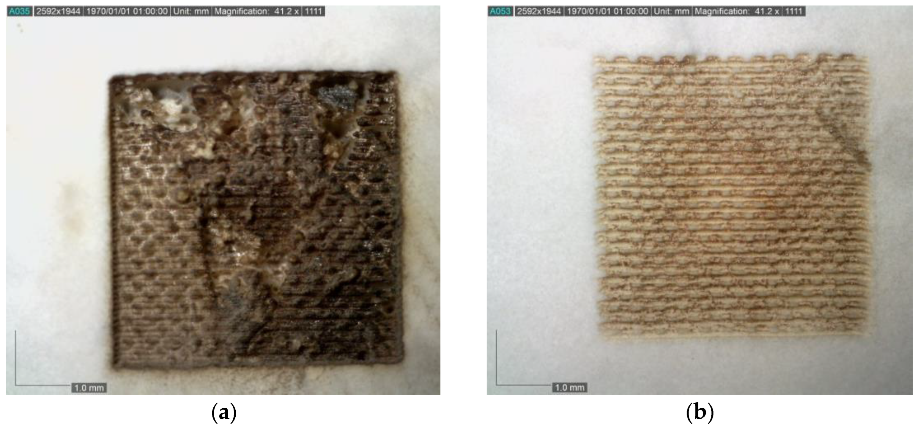
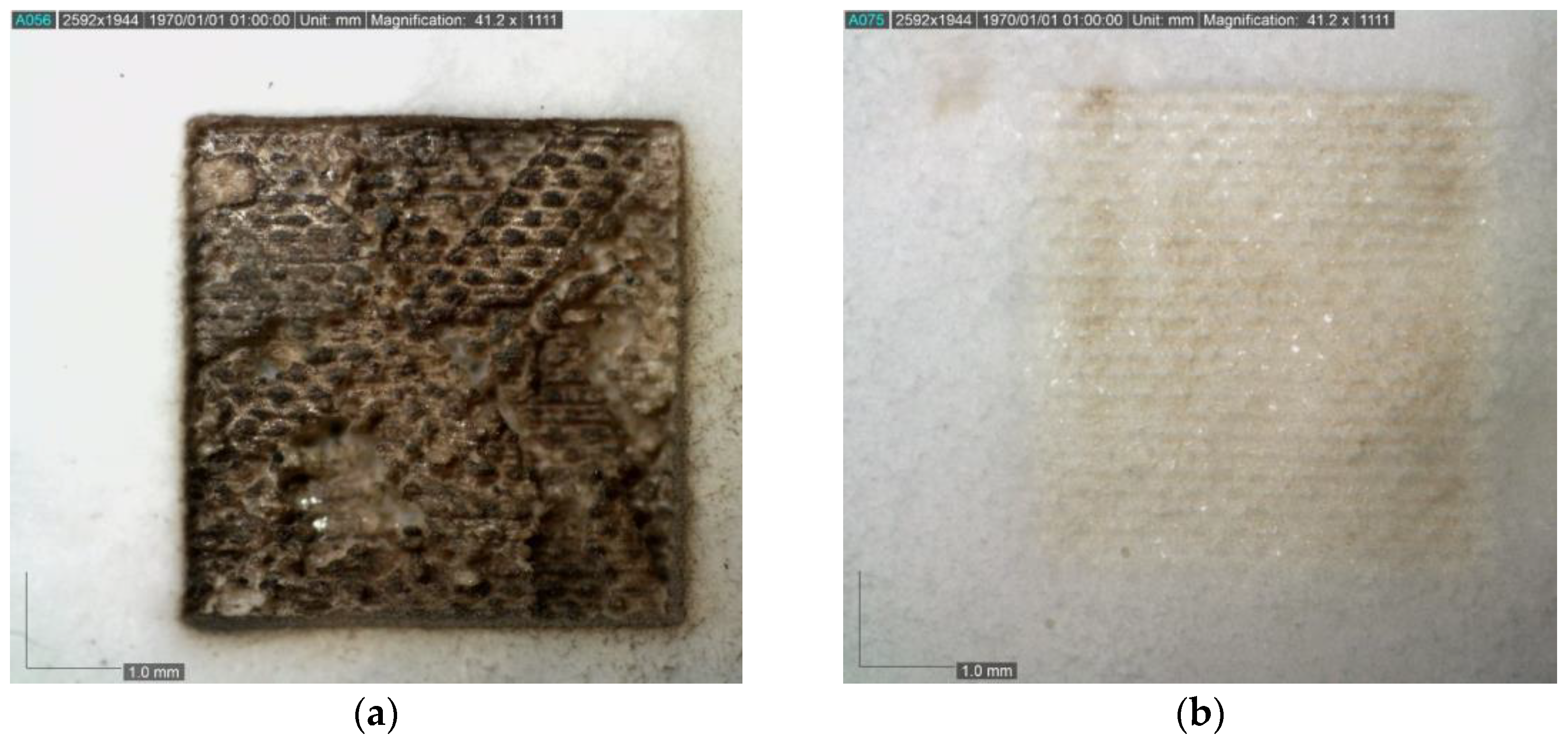
  • Higher laser power resulted in more visible engravings with a distinct, blackened outline due to burning, observed in both focused (Sample A) and defocused (Sample C) conditions. As laser power decreased, the visibility and depth of the engravings diminished, eventually reaching a point where material loss was negligible and the engraving became indiscernible. Slower laser head speeds led to greater burn and deeper engravings, attributable to prolonged exposure to the laser beam.
  • A linear relationship was observed between laser power and the Material Loss Index ( I M L ) in both Trials A and C. A linear relationship was also found between laser head speed and the IML in Trial B.

4. Discussion

The investigation into laser processing of mycelium-bonded composites (MBCs) highlights opportunities to enhance both the utility and market appeal of these sustainable materials. A key advantage of laser technology is its ability to perform material removal with minimal tool wear and waste, while maintaining the integrity of the surrounding delicate material. As a dry and additive-free process, laser engraving aligns with green manufacturing principles, avoiding the need for harmful chemicals or coolants.
The unpleasant odor of mycelium-based composites (MBCs) is a well-documented issue, primarily attributed to the biological nature of fungal growth, degradation of organic substrates, and residual moisture [21]. While laser engraving does not eliminate this disadvantage, it provides a tool to achieve a high degree of visual consistency on the surface, which is vital for consumer acceptance, thereby helping to overcome one of the main obstacles to the broader acceptance of MBCs [14,15]. This enhances the esthetic value of these environmentally friendly materials.
As a repeatable, non-contact method for surface patterning and texturing, laser engraving offers several advantages:
  • Consistent appearance across batches of MBCs, regardless of minor variations in the surface topography of the raw composite.
  • Reproduction of specific functional patterns (e.g., to improve adhesion for gluing or painting).
  • Objective assessment of the quality and thickness of the fungal skin on the surface of the mycelium-based composite.
The findings of this research have implications for a range of industrial sectors seeking sustainable alternatives to conventional materials. MBCs, enhanced by advanced laser-engraved designs, have potential applications in the following areas:
  • Integration into automated or robotic manufacturing workflows during MBC production, characteristic of Industry 4.0 practices [22].
  • Replacement of plastic in packaging applications, with customizable branding and informational labeling. This aligns with the growing trend toward biodegradable materials in disposable packaging [23].
  • Development of sustainable furniture lines featuring intricate engravings, leveraging laser technology that has long been adopted in the furniture industry [24],
  • Implementing environmentally friendly and energy-efficient materials for thermal and acoustic insulation, including use as wall and ceiling coverings, aided by the increasing popularity of laser engraving in the construction sector [25].
  • Incorporation of laser-processed biocomposites as product components in textiles, electronics, and consumer goods, supported by laser marking and engraving techniques widely used for materials like wood, leather, and fabrics [26].
  • Production of biodegradable pots and other ecological products with customized designs or functional markings for use in agriculture and horticulture [27].
The versatility offered by laser processing supports a broad adoption of MBCs across diverse markets. Furthermore, laser processing can reduce the need for additional surface treatments.

5. Conclusions

  • The increasing laser power enhances the material removal rate, leading to more pronounced and deeper engravings. However, when the laser beam is defocused, the intensity of material removal diminishes noticeably. This reduction occurs because a defocused beam spreads energy over a larger area, lowering the energy density required to reach the material’s ablation or vaporization threshold. In contrast, a focused laser beam concentrates thermal energy more effectively, enabling it to consistently meet and exceed this threshold across the entire irradiated zone. Consequently, focused laser processing achieves superior control and efficiency in material removal, making it the preferred configuration for engraving mycelium-bonded composites.
  • Based on our observations, a laser power around 20–25 W with a focused beam (zero defocus) and a carefully selected feed rate (e.g., around 1.5–2.0 m/s to avoid excessive burning as seen at very low speeds) appears to offer a promising balance for effective material removal while minimizing charring and optimizing surface quality in mycelium-based composites studied.
  • The quality of the laser beam focus is more critical than the power in the engraving of myco-composites. Although increasing laser power contributes to a higher material removal rate, this effect is significantly more pronounced when the beam is properly focused. These findings highlight the importance of precise beam control and focus in achieving optimal engraving results; however, the uneven surface of the myco-composite presents a significant challenge for accurate focus adjustment.
  • Optimizing the laser feed rate is crucial for balancing material removal and surface quality in mycelium-based composites. While slower speeds increase dwell time and enhance ablation, excessively low speeds lead to thermal overload, resulting in burning and surface degradation. Therefore, precise control of energy input per unit area—through careful laser power and feed rate adjustment—is essential to achieve effective and clean engraving without exceeding the material’s thermal tolerance.
Overall, the obtained results suggest that the material loss index ( I M L ) can be controlled by adjusting the laser power and head speed, and the relationships between these parameters and I M L are linear. This study’s results provide data on material removal rates as a function of laser parameters, uniquely addressing the previously unexplored domain of laser engraving for myco-composites. The results hold promise for producers seeking to capitalize on the sustainability and customization benefits of MBCs.

Author Contributions

Conceptualization, M.S.; methodology, M.S. and G.P.; validation, M.S., G.P. and A.B.; formal analysis, A.B.; investigation, G.P.; resources, M.S.; data curation, G.P.; writing—original draft preparation, M.S. and A.B.; writing—review and editing, M.S.; visualization, G.P. and M.S.; supervision, M.S.; project administration, M.S.; funding acquisition, M.S. All authors have read and agreed to the published version of the manuscript.

Funding

This research received no external funding.

Data Availability Statement

The data presented in this study are available upon reasonable request from the corresponding author.

Acknowledgments

The authors thank Grzegorz Cofta for creating the test samples used in this study.

Conflicts of Interest

The authors declare no conflicts of interest.

References

  1. Bayer, E.; McIntyre, G.; Swersey, B.L. Method for Producing Grown Materials and Products Made Thereby. U.S. Patent 9,485,917 B2, 8 November 2016. (Filed 12 December 2007, and published as US 2008/0145577 A1 on 19 June 2008). [Google Scholar]
  2. Armstrong, R. The Post-Epistemological Details of Oceanic Ontologies. Archit. Des. 2014, 84, 112–117. [Google Scholar] [CrossRef]
  3. Holt, G.A.; Mcintyre, G.; Flagg, D.; Bayer, E.; Wanjura, J.D.; Pelletier, M.G. Fungal Mycelium and Cotton Plant Materials in the Manufacture of Biodegradable Molded Packaging Material: Evaluation Study of Select Blends of Cotton Byproducts. J. Biobased Mat. Bioenergy 2012, 6, 431–439. [Google Scholar] [CrossRef]
  4. Rapp, R. On Mycohuman Performances: Fungi in Current Artistic Research. Fungal. Biol. Biotechnol. 2019, 6, 22. [Google Scholar] [CrossRef] [PubMed]
  5. Abhijith, R.; Ashok, A.; Rejeesh, C.R. Sustainable Packaging Applications from Mycelium to Substitute Polystyrene: A Review. Mater. Today Proc. 2018, 5, 2139–2145. [Google Scholar] [CrossRef]
  6. Jones, M.; Mautner, A.; Luenco, S.; Bismarck, A.; John, S. Engineered Mycelium Composite Construction Materials from Fungal Biorefineries: A Critical Review. Mater. Des. 2020, 187, 108397. [Google Scholar] [CrossRef]
  7. Rashdan, W.; Fathy Ashour, A. “Growing Design”: The Role of Mycelium-Based Materials in Interior and Furniture Design. Int. J. Des. Objects 2024, 18, 37–62. [Google Scholar] [CrossRef]
  8. Wattanavichean, N.; Phanthuwongpakdee, J.; Koedrith, P.; Laoratanakul, P.; Thaithatgoon, B.; Somrithipol, S.; Kwantong, P.; Nuankaew, S.; Pinruan, U.; Chuaseeharonnachai, C.; et al. Mycelium-Based Breakthroughs: Exploring Commercialization, Research, and Next-Gen Possibilities. Circ. Econ. Sust. 2025, 1–43. [Google Scholar] [CrossRef]
  9. Chayaamor-Heil, N.; Houette, T.; Demirci, Ö.; Badarnah, L. The Potential of Co-Designing with Living Organisms: Towards a New Ecological Paradigm in Architecture. Sustainability 2024, 16, 673. [Google Scholar] [CrossRef]
  10. Le Ferrand, H. Critical Review of Mycelium-Bound Product Development to Identify Barriers to Entry and Paths to Overcome Them. J. Clean. Prod. 2024, 450, 141859. [Google Scholar] [CrossRef]
  11. Elsacker, E.; Vandelook, S.; Brancart, J.; Peeters, E.; De Laet, L. Mechanical, Physical and Chemical Characterisation of Mycelium-Based Composites with Different Types of Lignocellulosic Substrates. PLoS ONE 2019, 14, e0213954. [Google Scholar] [CrossRef] [PubMed]
  12. Appels, F.V.W.; Camere, S.; Montalti, M.; Karana, E.; Jansen, K.M.B.; Dijksterhuis, J.; Krijgsheld, P.; Wösten, H.A.B. Fabrication Factors Influencing Mechanical, Moisture- and Water-Related Properties of Mycelium-Based Composites. Mater. Des. 2019, 161, 64–71. [Google Scholar] [CrossRef]
  13. Jones, M.; Huynh, T.; Dekiwadia, C.; Daver, F.; John, S. Mycelium Composites: A Review of Engineering Characteristics and Growth Kinetics. J. Bionanosci. 2017, 11, 241–257. [Google Scholar] [CrossRef]
  14. Bonenberg, A.; Sydor, M.; Cofta, G.; Doczekalska, B.; Grygorowicz-Kosakowska, K. Mycelium-Based Composite Materials: Study of Acceptance. Materials 2023, 16, 2164. [Google Scholar] [CrossRef] [PubMed]
  15. Lewandowska, A.; Bonenberg, A.; Sydor, M. Mycelium-Based Composites: Surveying Their Acceptance by Professional Architects. Biomimetics 2024, 9, 333. [Google Scholar] [CrossRef] [PubMed]
  16. Kúdela, J.; Andrejko, M.; Kubovský, I. The Effect of CO2 Laser Engraving on the Surface Structure and Properties of Spruce Wood. Coatings 2023, 13, 2006. [Google Scholar] [CrossRef]
  17. Gusts, A.S.; Adijāns, I. Investigation of Laser Texturing Parameters and Their Impact on Glue Adhesion Properties on the Surface of Birch Plywood. In Proceedings of the 15th International Scientific and Practical Conference, Rezekne, Latvia, 22 June 2024; Rezekne Academy of Technologies: Rēzekne, Latvia, 2024; Volume 3, pp. 387–392. [Google Scholar]
  18. Lazov, L.; Deneva, H.; Narica, P. Laser Marking Methods. In Proceedings of the International Scientific and Practical Conference, Rezekne, Latvia, 16 June 2015; Rezekne Academy of Technologies: Rēzekne, Latvia, 2015; Volume 1, pp. 108–115. [Google Scholar]
  19. Ganeev, R.A. Laser-Surface Interactions; SpringerLink Bücher; Springer Dordrecht: Dordrecht, The Netherlands, 2014; ISBN 978-94-007-7340-0. [Google Scholar] [CrossRef]
  20. Jurek, M.; Wagnerová, R. Laser Beam Calibration for Wood Surface Colour Treatment. Eur. J. Wood. Prod. 2021, 79, 1097–1107. [Google Scholar] [CrossRef]
  21. Camere, S.; Karana, E. Fabricating Materials from Living Organisms: An Emerging Design Practice. J. Clean. Prod. 2018, 186, 570–584. [Google Scholar] [CrossRef]
  22. Nath, A.K.; Sarkar, S.; Muvvala, G.; Karmakar, D.P.; Chakraborty, S.S.; Mullick, S.; Madhukar, Y.K. LASER-Based Manufacturing as a Green Manufacturing Process. In Sustainable Material Forming and Joining; Narayanan, R.G., Gunasekera, J.S., Eds.; CRC Press: Boca Raton, FL, USA, 2019; pp. 303–365. ISBN 978-1-315-16314-7. [Google Scholar]
  23. Reichert, C.L.; Bugnicourt, E.; Coltelli, M.-B.; Cinelli, P.; Lazzeri, A.; Canesi, I.; Braca, F.; Martínez, B.M.; Alonso, R.; Agostinis, L.; et al. Bio-Based Packaging: Materials, Modifications, Industrial Applications and Sustainability. Polymers 2020, 12, 1558. [Google Scholar] [CrossRef] [PubMed]
  24. Wieloch, G.; Pohl, P. Use of Lasers in the Furniture Industry. In Proceedings of the Research Trends, Instrumentation, and Applications in Metrology and Materials Processing, Szczecin-Świnoujście, Poland, 1 March 1995; Society of Photo Optical Instrumentation Engineers: Szczecin-Świnoujście, Poland, 1995; Volume 2202, pp. 604–607. [Google Scholar]
  25. Mehra, R.; Mohal, S.; Singh, H.; Chaubey, S.K. Investigations on Machining of Hybrid Glass Fiber-Reinforced Polymer Using Laser Engraving Machine. J. Materi. Eng. Perform. 2025. [Google Scholar] [CrossRef]
  26. Angelova, Y.P. Factors Influencing the Laser Treatment of Textile Materials: An Overview. J. Eng. Fiber. Fabr. 2020, 15, 1558925020952803. [Google Scholar] [CrossRef]
  27. Hall, C.R.; Campbell, B.L.; Behe, B.K.; Yue, C.; Lopez, R.G.; Dennis, J.H. The Appeal of Biodegradable Packaging to Floral Consumers. HortScience 2010, 45, 583–591. [Google Scholar] [CrossRef]
Figure 1. Cylindrical mecelium-bonded composite (MBC) samples prior to laser engraving.
Jcs 09 00389 g001
Figure 2. Graphical interpretation of the Material Loss Index I M L .
Jcs 09 00389 g002
Figure 3. The Material Loss Index ( I M L ) values depending on the laser power P L for samples A and C.
Jcs 09 00389 g003
Figure 4. Tests on sample A with decreasing laser power P L (laser is focused): (a)—first test with P L = 50   W ; (b)—last visible (7th) test with P L = 20   W .
Jcs 09 00389 g004
Figure 5. Tests on sample C with decreasing laser power P L (the laser is defocused by 1 mm): (a)—first test with P L = 50   W ; (b)—last visible (7th) test with P L = 20   W .
Jcs 09 00389 g005
Figure 6. Material Loss Index ( I M L ) values depending on the laser head speed v L in Trial B.
Jcs 09 00389 g006
Figure 7. Tests on sample B with decreasing head feed speed: (a)—first test with feed speed of 2.24 m/s; (b)—10th test with feed speed of 0.98 m/s.
Jcs 09 00389 g007
Table 1. Trial A, with decreasing power of laser beam.
Test No. Power   of   the   Laser   Beam ,   P L (W) Head   Speed   ( Feed   Rate ) ,   v L (m/s)
1502.24
245
340
435
530
625
720
815
910
105
Table 2. Trial B, with variable laser head speed (feed rate).
Test No. Power   of   the   Laser   Beam ,   P L (W) Head   Speed   ( Feed   Rate ) ,   v L (m/s)
1502.24
22.10
31.96
41.82
51.68
61.54
71.40
81.26
91.12
100.98
Table 3. Trial C, with laser power as the variable, and shifting the laser focus by 1 mm.
Test No. Power   of   the   Laser   Beam ,   P L (W) Head   Speed   ( Feed   Rate ) ,   v L (m/s)Leaser Defocusing (mm)
1502.241
245
340
435
530
625
720
815
910
105
Table 4. Variation in Material Loss Index for Samples A and C as a function of laser power.
Laser   Power ,   P L (W) Material   Loss   Index ,   I M L (mm2)
Sample ASample C
(Laser Defocused by 1 mm)
502.391.85
452.260.99
401.610.87
351.080.64
300.940.49
250.100.54
200.350.01
1500
1000
500
Table 5. Material Loss Index I M L values in Trial B as a function of laser head speed (vL).
Laser   Head   Speed ,   v L (m/s) Material   Loss   Index ,   I M L (mm2)
2.241.21
2.11.50
1.961.83
1.821.69
1.681.89
1.542.22
1.42.31
1.262.37
1.123.04
0.982.93
Disclaimer/Publisher’s Note: The statements, opinions and data contained in all publications are solely those of the individual author(s) and contributor(s) and not of MDPI and/or the editor(s). MDPI and/or the editor(s) disclaim responsibility for any injury to people or property resulting from any ideas, methods, instructions or products referred to in the content.

