Abstract
This paper analyzed the behavior of polymer composite materials reinforced with randomly oriented short natural fibers (hemp, flax, etc.) subjected to external stresses under quasistatic contact conditions with dry Coulomb friction. We presumed the composite body, a 2D flat rectangular plate, being in frictional contact with a rigid foundation for the quasistatic case. The manuscript proposes the finite element method approximation in space and the finite difference approximation in time. The problem of quasistatic frictional contact is described with a special finite element, which can analyze the state of the nodes in the contact area, and their modification, between open, sliding, and fixed contact states, in the analyzed time interval. This finite element also models the Coulomb friction law and controls the penetrability according to a power law. Moreover, the quasi-static case analyzed allows for the description of the load history using an incremental and iterative algorithm. The discrete problem will be a static and nonlinear one for each time increment, and in the case of sliding contact, the stiffness matrix becomes non-symmetric. The regularization of the non-differentiable term comes from the modulus of the normal contact stress, with a convex function and with the gradient in the sub-unit modulus. The non-penetration condition was achieved with the penalty method, and the linearization was conducted with the Newton–Raphson method.
1. Introduction
The contact between two solid bodies made of composite materials or between a composite body and a rigid foundation is a complex physical process that describes the opposing resistance to penetration, in the normal direction, and a relative tangential motion. The interaction between the two bodies made of composite materials in contact can be described by the laws of the contact phenomenon and the laws of friction, which describe the relationships between the displacements and the forces acting on the contact area.
In the analyzed time interval, the frictional states on the contact boundary can change among open, sliding, or fixed. This paper modeled the contact problem using the quasi-static case and used incrementally-iterative algorithms. In the specialized literature, there are many incremental approaches to elastic contact problems.
The manuscript analyzed a composite made up of 50% polymer and 50% short natural fibers, ±10%, randomly oriented in a homogeneous mixture. The properties of this composite material make it highly appreciated in industry, especially in the field of furniture and household appliances.
The roughness of the contact area and implicitly the behavior of the contact phenomenon depend on the nature of the composite material. There are studies in the specialized literature for this type of composite material that have addressed the behavior of contact problems with different friction laws and analyzed fiber-reinforced composites taking into account their tribological characteristics. The tribological characteristics of the composites are related to the fiber to polymer volumetric ratio and the roughness of the contact area. These relations can be expressed when analyzing the contact with friction behavior of the composite. In this regard, we mention [1,2,3,4].
The friction coefficient on the contact area depends on the proportions of the components in the composite material and its rigidity. The contact area in composite materials is much rougher than in the case of metals. In addition, the contact area will contain randomly distributed soft components (natural hemp fibers) and hard components (the polypropylene matrix).
In the contact problem, the anisotropy of the contact area is more important than the anisotropy of the composite material [5,6,7]. There are still many open problems in the study of composite materials with randomly oriented natural fibers.
We considered the composite as homogeneous (i.e., the polymer and the randomly oriented short natural fibers) well mixed. For the mathematical model, we assumed the composite body to be viscoelastic with linear elasticity. The mathematical model consisted of a series of variational inequalities that were approximated with the finite element method [8,9,10,11], in which the non-differentiable term given by the law of dry friction contact according to Coulomb’s law is replaced by a friction functional regularized with a convex function. The regularization method consists of the approximation of the non-differentiable term in the contact condition with a differentiable term.
2. Materials and Methods
2.1. Quasistatic Formulation of Contact Problems with Friction for Composite Materials
Contact problems for composite materials consist of determining the displacements, deformations, and stresses in two viscoelastic, isotropic linear bodies in contact, or of a composite body in contact with a rigid support, subjected to various friction laws.
In this manuscript, we analyzed the second variant when the traction forces act at a speed sufficiently low that the inertial effects can be neglected.
Let there be a viscoelastic composite body which at the moment t = 0 is set within the domain , where d = 2 or d = 3, with the Lipschitz boundary, shared in three mutually disjunctive parts having the measure
This is denoted by , and , , and . The body is fixed on the boundary , where the displacements are set to zero, that is, the body is embedded in that portion of the boundary, having tractions of intensity h acting on the boundary , and the boundary being the area in contact with the rigid foundation. Here, we applied the Signorini condition and Coulomb friction law. Volume forces with the intensity f act in Ω. We have noted the following: displacement vector, tension tensor, , deformation tensor are the normal and tangential components of the tension tensor and displacement vector, respectively.
We considered the constitutive relation Kelvin–Voigt in the viscoelastic case.
where și with , are the components of the elastic and viscoelastic tensors, respectively, which satisfy the ellipticity condition.
The classical quasistatic equilibrium equations are:
where n is the external unit normal on is the friction coefficient that depends on the tangential velocity, and is the deformation velocity.
Relation (1) is the equilibrium equation, (3) and (4) are the Dirichlet and Neumann boundary conditions, respectively, (5) is the Signorini contact condition, (6) and (7) are the Coulomb type friction laws, and (8) are the initial conditions.
Because of the Coulomb friction law, the problem becomes time dependent, and all the values can be time dependent. This makes the studied process irreversible and dependent on the loading way. Thus, the final displacements and tensions depend on the way the volume forces f and tractions h change in time, and not only their final values. The numerical algorithm proposed in this work can describe this by performing incremental loadings, in small steps, followed by iterative solutions and testing the convergence of the chosen method.
The quasistatic problem with dry friction following the Coulomb’s law for homogeneous and viscoelastic composite materials can be formulated as follows:
Problem P1: Find out the displacements and tensions that satisfy Equations (1)–(8) for any given moment t ∈ [0,T] and the initial condition u(x,0) = u₀ on .
Physical arguments and mathematical difficulties regarding the local friction laws (6) and (7) made Duvant [12], Oden and Pires [13], and Cocu [14] take into consideration the nonlocal, even nonlinear, friction laws derived from (6) and (7) by replacing || with a convenient regularized R(). These models fit even better, given that in the case of composite materials reinforced with fibers, the contact area has a micro-structure consisting of pronounced roughness, no longer being a perfect plain surface, and as the normal force N on the contact area gradually increases, the asperities gradually flatten to an equilibrium with the normal forces. However, the normal force is not single pointed but distributed over the real contact area, and thus the tangential tension is also distributed over the real contact area, whose shape is influenced by surfaces with deformed asperities in contact.
In the accepted hypothesis, these asperities can be modeled as smooth periodic perturbations of the contact area with a period ε, where ε > 0; in this case, Coulomb’s law becomes:
where δ is Dirac’s distribution for a point x.
However, because the contact area is finite, we can assume that:
where is a series of test functions that usually approximate , and is the radius of the deforming contact area.
However, (9) only applies in the case of a normal force acting only in point y, while in our case, where N is distributed, we obtain:
where ∗ stands for the convolution operation.
Generalizing, a convenient regularization might be defined as:
where
C₀ is constant and is a measure of the characteristic radius of the deformed asperities on the contact area.
Thus, for > 0, the slipping tangential tension is proportional to R(), which is the weighted average of in a vicinity of radius 2 on the contact area.
Oden and Pires [15] considered the problem of contact between an elastic body and a rigid support with a nonlocal and nonlinear friction law for the static case on and d = 3, ().
For the quasistatic case, it will be
where , is an increasing function, piecewise differentiable so that and , and is a measurement of the stiffness of the asperities’ junctions on the contact area of the composite material. If there is no reversal of the loading direction, the following form can be chosen for the function :
The friction laws (12) and (13) are general laws containing particular cases (i.e., for the static and quasi-static cases, respectively):
- (a)
- if and , we obtain local but nonlinear laws;
- (b)
- if and , we obtain nonlocal laws;
- (c)
- if and , we obtain classical Coulomb’s laws;
- (d)
- if and , if is known, the contact area is known, a priori;
- (e)
- if we obtain the classical problem of frictionless unilateral contact.
The unilateral Signorini-type contact conditions (5) represent impenetrability conditions, valid for smooth contact surfaces, and remain smooth throughout the process. These can be represented by functions in C1(Ω) as continuous with continuous derivatives.
Both the theoretical and experimental data led to the conclusion that a power law should be adopted to model the normal contact tension variation in accordance with the penetration degree for sufficiently small loadings.
These aspects led Oden and Martins [16] to consider the following power law relationship:
In the case of a deformable body in contact with a rigid support, > 0 and > 0 are experimentally determined constants representing the contact physical characteristics, the notation represents the positive part (i.e., = max (x, 0)), and g is the distance between the rigid surface and the highest asperities of the body.
Note that the Signorini law (5) can be formally obtained from (14), making .
The contact with friction problem for a viscoelastic body in contact with a rigid support can be therefore formulated as:
Problem P2: Find out the displacements and tensions that satisfy Equations (1)–(8), (13) and (14) and the initial condition
The proposed friction law is a generalization of the friction law considered so far to be isotropic.
For the case d = 3 (i.e., , we denote by , the main orthotropic axes defined on the surface portion , with and , then instead of Relations (7) and (8), we may consider, without essential changes, the following orthotropic friction law, suitable for composite materials reinforced with natural fibers oriented in two perpendicular directions:
2.2. Variational Formulation of Quasistatic Contact Problems for Composite Materials
In order to numerically solve the quasistatic contact problem using the finite element method, we need to express it variationally. We start by introducing the following function spaces:
with , we define
In order to obtain variational formulations for P2, we used Green type relations, where for u, v ∈ V we obtained:
The Signorini condition (5) and the local friction laws (6) and (7) will accordingly become:
By using Green’s formula on Ω, we obtain the following variational expression of problem P1:
Problem P’1: Find out u: Q → K so that and
Analogous, a variational expression for problem P2 is:
Problem P‘2: Find out u: Q →V so that and
Please note that the inequalities (23) and (24) can be written in an elegant synthetic mathematical form using the notion of sub-differentials.
In order to solve these problems numerically, we need to take into account approximations of these problems, obtained by discretization using the finite element method in space and finite differences in time. This procedure leads to incremental formulations, to whom we may apply, in principle, the same methods as for static problem cases.
2.3. Incremental Formulations Obtained by Temporal Discretization
We obtained the incremental formulations from the variational formulations by replacing the temporal derivatives of displacements with finite differences. The quasistatic problems were solved step by step: at each step, we calculated the small deformations and displacements, obtained as a result of the small incremental changes of the applied forces, and we added them to the values calculated in the previous step.
Thus, the dependence on the way of loading is neglected in every increment; this sequence of steps also takes into account how the applied forces vary in time, which is very important for describing the contact state of the points on the contact boundary.
In order to obtain incremental formulations of the quasistatic contact problems, we introduced a partition of the time interval and the following notations.
Derivative, by the time t, can be approximated using the finite differences formula:
Using the above notations, the time discretized form of the problem P‘1 becomes:
Denoting by the set:
, we see that:
, and from (27), we obtain:
Problem P’’1: We looked for so that
where we denoted:
which, using Green’s formula and considering the equilibrium in step m due to the displacement , can also be written as:
One can note that the incremental inequality (28) has a similar form with a quasi-variational inequality describing a static problem, and the condition ensuring the impenetrability condition , m = 0, 1, …, p − 1.
Similarly, problem P′2 leads to the incremental one.
Problem P’’2: Find out the sequence with , where is the inequality solution.
It can be seen that the quasi-variational inequality (29) is equivalent with the following incremental, time independent (static) problem.
It is required that , so that
The existence and uniqueness of the solutions of the quasi-variational inequations have been analyzed by Anderson [16], Klarbing [17], and Cocu [14]. The necessary conditions for this are as follows: the friction coefficient should be sufficiently small, slipping directions on the contact area should be predictable, and Hooke’s law should be dependent on the velocity of the deformation.
All of these restrictions are met in the case of quasistatic contact in viscoelastic materials such as natural fiber-reinforced composites.
To correctly model these characteristics, the incremental and iterative Newton-Raphson method was used.
2.4. Approximation Using the Finite Elements Method and the Description of the Incremental and Iterative Algorithms
2.4.1. The Existence and the Uniqueness of the Solution of the Incremental Problem: Contact Finite Element with Friction
Using the standard procedure for the finite element method, the approximation of the variational Equation (26) can be made in the finite dimensional space For a certain (h > 0) that defines the fineness of the partition and the approximations of the displacements for the time are elements, . In each finite element in the displacement fields from within a finite element are interpolated between the nodal values of the element as:
where is the node number of the finite element , and is the form function associated with the nodal point i of the finite element .
For every incremental step of Problem P″2, we took an internal approximation of the finite element type, with the discretization parameter [18] as:
Problem P″2h: Find out so that
Given that for every time increment the problem P2 is a static one, the existence of the finite element approximate solution develops into proving the existence of the solution of inequation (31), which is a fixed point for the application , which associates , where the element is defined as
so that the series approaches , where because the map is a contraction.
Proof. The proof can be found in [14] for a sufficiently small frictional coefficient.
The matrix form of the equilibrium equation approximated with the finite element method for Problem P″2h is:
Problem P″2hm: Find a function so that
using the approximation with the finite element method , according to the notations (16)–(22). The use of the finite element method in the study of composites can be seen in [19,20,21,22,23,24]. Where K is the stiffness matrix, and is the loadings vector, obtained from (18), and (22), respectively, by approximating and assembling with finite elements. The P and J matrices, obtained via (20) and (21), respectively, represent the nodal forces vector and the friction forces on the contact boundary , respectively, obtained by assembling the contact finite elements.
System (33) is an algebraic system of equations, resulting from the approximation of the spatial variables with the finite element method and the approximation of the temporal variables with finite differences, resulting from the boundary conditions that also depend on the time t.
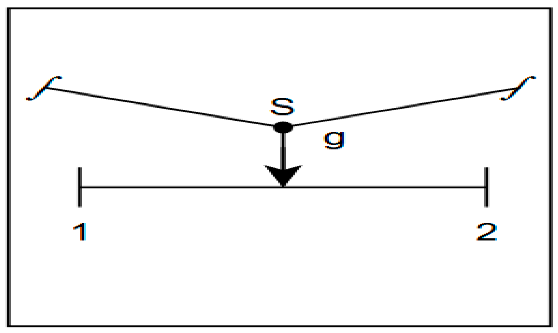
The contact finite element in 2D (see Figure 1) consists of three nodes on the contact boundary, two “master” nodes belonging to a body (or the rigid support) and a “slave” node belonging to the second body. This contact finite element is a node-segment type and has linear, first degree, interpolation functions and models the friction law and the non-penetration or penetration condition by a power type law [25,26].
Figure 1.
Contact finite element in 2D. 1 and 2 are the master nodes, S is the slave node and g is the gap.
2.4.2. The Newton–Raphson Algorithm in Iterative and Incremental Solving of Nonlinear Algebraic Systems
Let the stiffness matrix containing also the contribution of the frictional contact; for this reason, the matrix will contain both nonlinearities and non-symmetries, caused by the slipping contact and the anisotropicity of the composite material. We considered a partition of the time interval [0,T] = with 0 = < ... < and denoted , a time sub-interval where the system can be taken as static. We assumed that we found the solution on the sub-interval , corresponding to this time step, and searched for a solution on the sub-interval , applying iteratively the Newton–Raphson algorithm to obtain the solution , which satisfies the condition < TOL, where index n defines the iteration on this sub-interval and TOL is a positive constant, sufficiently small, stop condition for the iteration. Considering (33), we denoted the matrix function as follows:
or in the incremental and iterative form = 0, n and knowing it is differentiable in and is a solution on the sub-interval (i.e., we developed the Taylor series for function T and retained only the first term, thus resulting in the Newton method:
Finally, on interval [0,T], the solution for the quasistatic problem will contain the solutions on every time sub-interval , meaning that {U0, U1,..., UT}, which correspond to the incremental loadings on each sub-interval.
A synthetic presentation of the algorithm of the quasistatic contact problem is given below:
- Initialize data t0 = 0, k = 0, n = 0,
- Calculate the stiffness matrix K of the composite;
- Calculate the contact nodal forces P and the frictional contact forces J, assemble the global stiffness matrix KN and the global incremental loading vector on the sub-interval , followed by resolving with the Newton–Raphson algorithm {};
- Check the convergence: if < TOL, go to (vii);
- Else go to (vi);
- Update the displacement fields, the condition + , and the increments of the loading forces ;
- n = n + 1 and go to (ii);
- Exit.
2.4.3. Numerical Simulation
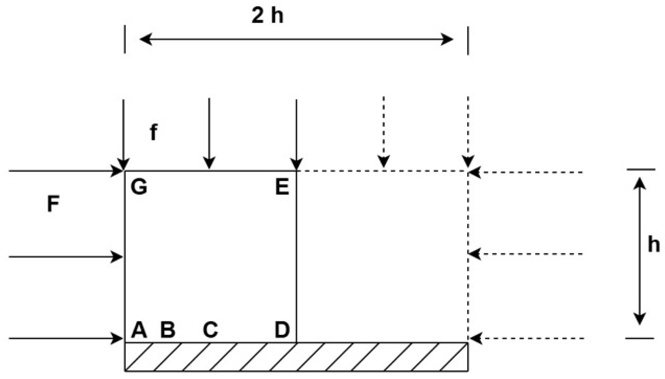
For the numerical simulation with finite elements, we chose a classical test used by many authors [27,28]. The test consists of a plane composite plate made of 50% polypropylene and 50% hemp fibers, ±10%, whose elasticity module Ec was determined through measurements in [29] using the resonance method. The plate is in dry friction contact with a rigid support, the contact area being along the length of the plate. This test has the advantage of being very simple geometrically and symmetric by the vertical axis in the middle of the rectangular plate. The stress loadings manifest in the plate plane (Figure 2), so that on the contact area with the rigid support, all of the possible contact states can appear: open, sliding, or fixed. For symmetry reasons, working with only half of the plate will suffice. Table 1 presents the zone distributions on the contact boundary, with the contact states open, sliding, or fixed, for different fiber to composite ratios, different stress loadings, and different friction coefficients, in the hypothesis of plane state deformation. Half of the plane plate was discretized into 128 quadrilateral finite elements (plane state deformation), and the contact area ABCD was discretized into 32 node-segment contact finite elements. The contact area ABCD had 17 nodes.
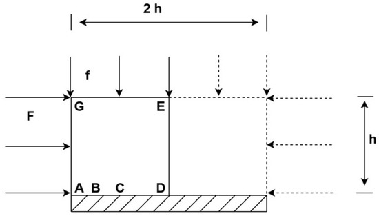
Figure 2.
Geometry (h = 40 mm) and stress loading. AB segment (boundary) is open contact, BC segment in a sliding contact, CD is stick contact. F stands for the horizontal force applied on the AG segment, and f for the vertical force applied on the GE segment of the plate.

Table 1.
The contact states on the ABCD boundary.
The elasticity module (Ec) formula for a composite material reinforced with random oriented fibers derives from composite theory as it is an extension of the law of the mixture, adjusted for the random orientation of the fibers. The most frequent form of this is:
where:
Ec = η Vf Ef + Vm Em
- -
- Vf, Vm are the volume ratios of the fibers and matrix (Vf + Vm = 1), respectively;
- -
- Ef, Em are the elasticity modules of the fibers and matrix, respectively,
- -
- η is an orientation factor that depends on the fiber length, orientation, adhesion, etc. (for random orientation in 3D, η ≈ 1/5; for random 2D, η ≈ 3/8).
Ec = (3/8)Vf Ef + Vm Em, in the case of 2D.
This formula is accepted in the literature [28,30,31] for composites reinforced with random oriented short fibers, mainly in studies on thermoplastic materials reinforced with natural or synthetic fibers. An extrapolation of the mechanical properties of the composite with its proportions was searched, but for this, the elasticity module E of every constituent is needed, (random oriented fibers + melted matrix), and not only the E of the composite at a 50–50% mixture.
However, it is known that the law of mixture is only approximately valid and does not take into account the shape or appearance of the fibers, their distribution or orientation, and most importantly, the fiber–matrix adhesion. To verify these aspects, it was necessary to find out the Young’s modulus E for hemp fiber and for molten polypropylene, in our case, from the specialized literature [32].
From the numerical simulation with the finite element method, we obtained the following results, which characterized with a good approximation, the mechanical properties of the composite material.
In Table 1, the distribution of contact states for EC = 130 GPa (see [32]) on the ABCD boundary is represented.
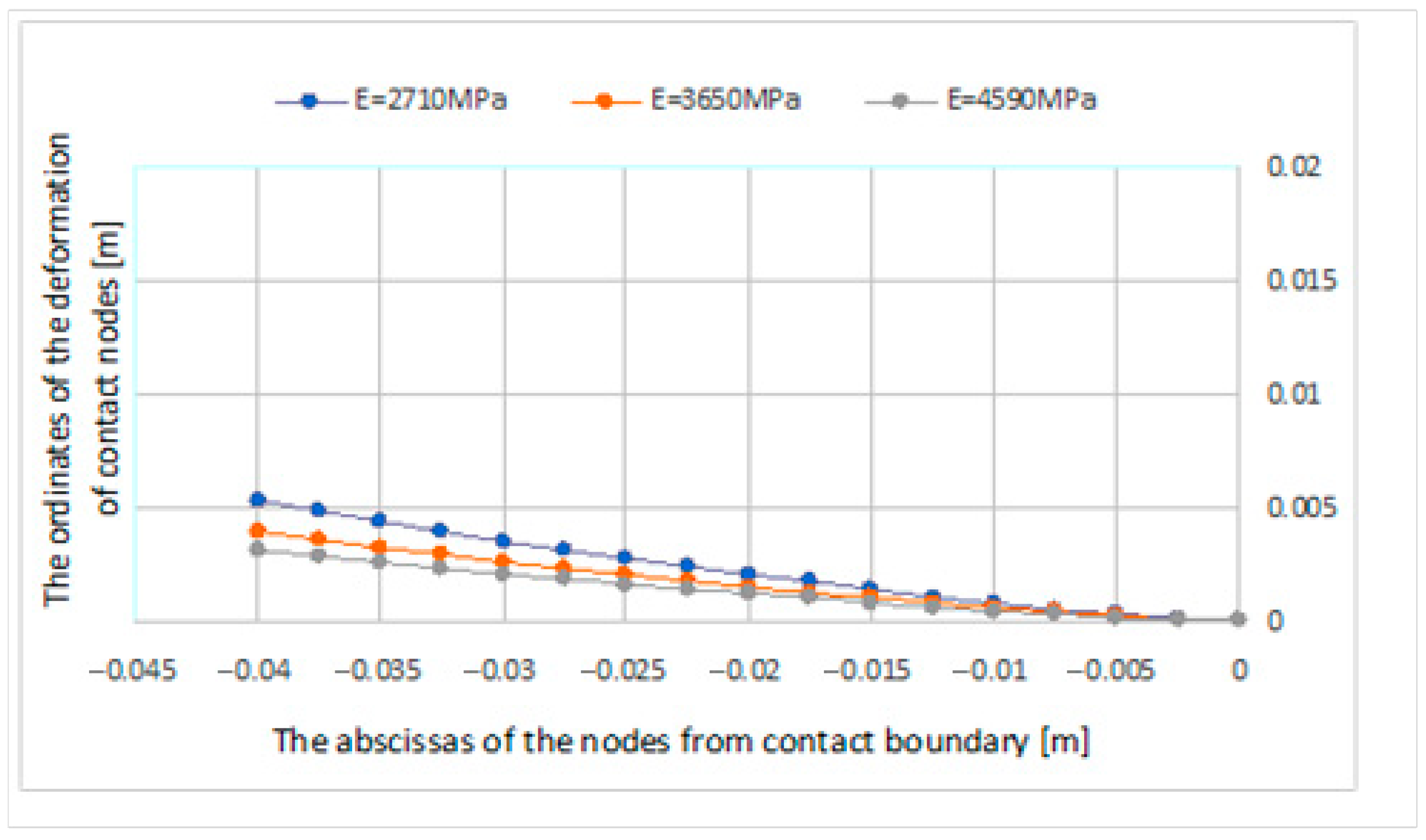
The ordinates of the deformation of the contact nodes, for three different values of Ec, is presented in Figure 3.
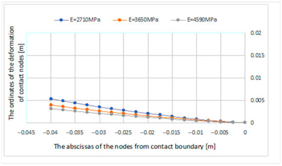
Figure 3.
The three deformations of the contact boundary for η = 0.2, μ = 0.01, Vf = 0.3 with Ec = 27 MPa, Vf = 0.5 with Ec = 3650 MPa, and Vf = 0.7 and Ec = 4590 MPa [31].
The main goal of this numerical simulation was to emphasize the importance of the ratios of the two constituents of the composite by analyzing the behavior of the contact states on the contact boundary in the case of the plane state deformation in Figure 2. The variation in the volume ratio of the fibers had an important influence on the distribution of the contact areas and states and on the normal and tangential contact loadings (see the results in Table 1 and Table 2).

Table 2.
Contact state for the composite material for Ec =3.65 GPa with variable η {0.25, 0.2, 0.15} and Vf = 0.5, ν = 0.39 with 17 contact nodes, where Ef = 30 GPa and Em =1.3 GPa [31].
The contact states for a composite with different values of the friction coefficient are presented in Table 3.

Table 3.
Contact state for the composite material with Ec = 130 GPa, ν = 0.3, Vf = 0.5, with 17 contact nodes, for different values of [31,32].
It was found that the composite properties were sufficiently well-characterized by the boundary area in contact with the rigid solid through harshness, friction coefficient, and the distribution of the contact areas states, which can be open, sliding, or fixed, and through the normal and tangential stress loadings in the contact area.
In practical problems, nonlinear problems often arise, as in our case, in the study of the elastic contact problem with friction for composites reinforced with randomly oriented short natural fibers. The implemented algorithms are restrictive and users have to continuously modify them to solve certain problems. For this reason, it is desirable to use modular software, whose modules can be selectively used to conveniently solve the desired problem with only the help of input data, without modifying the software. This was achieved and presented in this manuscript with the help of an interpretive language using macro-instructions that allowed us to build a variable algorithm, depending on the type of problem to be solved (see [33]).
For example, if in the numerical simulation the composite material is considered homogeneous and isotropic, the global stiffness matrix will be symmetric, and the TANG macro-instruction will be used; in the case of an anisotropic composite or if sliding contact also occurs on the contact area, the stiffness matrix will be non-symmetric, in which case the UTAN macro-instruction will be used.
If we want to form the right member of the equations, modified in the quasistatic case with time dependent boundary conditions, we will use the FORM macro-instruction; the macro-instruction SOLV will give the system solution U, the printing of the displacements is made with DISP, and of the stresses with STRE.
LOOP n and NEXT can be used to repeat n times the group of instructions between LOOP n and NEXT.
The macro-instructions set in the first column of Table 4 implements the Newton–Raphson linearization method, which at each step recalculates both the stiffness matrix and the free terms vector, thus requiring a high computational effort. This algorithm consists of 10 iterations and the displacements are printed every two iterations.

Table 4.
Software usage examples.
If the nonlinearities are not very pronounced, the modified Newton–Raphson method can be used, which forms the stiffness matrix only once and modifies the vector of free terms at each iteration; an example of this case is in the second column of Table 4.
This method is faster at computing time, but the convergence speed to the solution is lower than in the case of the classical method. For this reason, there are times when a combination of the two methods is a better approach: for example, case C in Table 4, when the stiffness matrix is formed only once every five iterations and the free term is updated in each iteration.
In the case where we want to solve an incremental and iterative nonlinear problem in which the load force is given incrementally, case D in Table 4 should be used, where:
- DT = initializes iterations;
- PROP = performs the proportional incremental loading;
- CV = performs the convergence test of the displacements.
3. Conclusions
One of the main results of this manuscript is that the properties of the composite materials were sufficiently well-characterized by the boundary area in contact with the rigid solid through the harshness, friction coefficient, and the distribution of the contact areas states, which could be open, sliding, or fixed, and through the normal and tangential stress loadings in the contact area. All of these are considered in the contact with friction phenomenon.
In addition, it was observed that composite materials exhibit a certain shape memory, pronounced damping, and a delayed return to the initial state.
The main contribution of the algorithm presented in this manuscript and proven by examples from the numerical simulations is that the mechanical behavior of the new composite obtained with different fiber volume proportions can be predicted with a good approximation.
Author Contributions
Conceptualization, M.R.A. and N.P.; Methodology, A.M.M. and T.S.; Software, N.P. and V.M.M.; Validation, M.R.A., A.M. and N.P.; Formal analysis T.S.; Data curation, T.S. and A.M.M.; Writing—original draft preparation, N.P. and M.R.A.; Writing—review and editing, A.M.M. and A.M.; Supervision, N.P. and T.S. All authors have read and agreed to the published version of the manuscript.
Funding
This research received no external funding.
Data Availability Statement
The original contributions presented in this study are included in the article. Further inquiries can be directed to the corresponding authors.
Conflicts of Interest
The authors declare no conflict of interest.
References
- Rodriguez-Tembleque, L.; Buroni, F.; Abascal, R.; Sáez, A. Analysis of FRP composites under frictional contact condition. Int. J. Solids Struct. 2013, 50, 3947–3959. [Google Scholar] [CrossRef]
- Alzweighi, M.; Tryding, J.; Mansour, R.; Borgqvist, E.; Kulachenko, A. Anisotropic damage behavior in fiber-based materials: Modeling and experimental validation. J. Mech. Phys. Solids 2023, 181, 105430. [Google Scholar] [CrossRef]
- Pickering, K.L.; Efendy, M.G.A.; Le, T.M. A review of recent developments in natural fibre composites and their mechanical performance. Compos. Part A Appl. Sci. 2016, 83, 98–112. [Google Scholar] [CrossRef]
- Abdollahiparsa, H.; Shahmirzaloo, A.; Teuffel, P.; Blok, R. A review of recent developments in structural applications of natural fiber-Reinforced composites (NFRCs). Compos. Adv. Mater. 2023, 32, 1–18. [Google Scholar] [CrossRef]
- Vlassak, J.J.; Ciavarella, M.; Barber, J.R.; Wang, X. The indentation modulus of elastically anisotropic materials for indenters of arbitrary shape. J. Mech. Phys. Solids 2003, 51, 1701–1721. [Google Scholar] [CrossRef]
- Ning, X.; Lovell, M.R.; Slaughter, W.S. Asymptotic solutions for axisymmetric contact of a thin, transversely isotropic elastic layer. Wear 2006, 260, 693–698. [Google Scholar] [CrossRef]
- Bagault, C.; Nélias, D.; Baietto, M.C.; Ovaert, T.C. Contact analyses for anisotropic half-space coated with an anisotropic layer: Effect of the anisotropy on the pressure distribution and contact area. Int. J. Solids Struct. 2013, 50, 743–754. [Google Scholar] [CrossRef]
- Birleanu, C.; Udroiu, R.; Cioaza, M.; Pustan, M.; Paul, B.; Vilau, C. The Effect of fiber Weight Fraction on Tribological Behavior for Glass Fiber Reinforced Polymer. Polymers 2025, 17, 720. [Google Scholar] [CrossRef]
- Tserpes, K.; Sioutis, I. Advances in Composite Materials for Space Applications: A Comprehensive Literature Review. Aerospace 2025, 12, 215. [Google Scholar] [CrossRef]
- Goda, T.; Vàradi, K.; Wetzel, B.; Friedrich, K. Finite element simulation of the fiber–matrix debonding in polymer composites produced by a sliding indentor: Part II: Parallel and anti-parallel fiber orientation. J. Compos. Mater. 2004, 38, 1607–1618. [Google Scholar] [CrossRef]
- Vàradi, K.; Nèder, Z.; Friedrich, K.; Flöck, J. Finite-element analysis of a polymer composite subjected to a ball indentation. Compos. Sci. Technol. 1999, 59, 271–281. [Google Scholar]
- Duvaut, G. Equilibre d’un solide elastique avec contact unilateral et frottement de Coulomb. C. R. Acad. Sc. Paris 1980, 290, 263–265. [Google Scholar]
- Oden, J.T.; Pires, E. Contact Problems in Elastostatics with Non-Local Friction Laws; TICOM Report; The University of Texas at Austin: Austin, TX, USA, 1981; pp. 81–112. [Google Scholar]
- Cocu, M. Existence of solutions of Signorini problems with friction. Int. J. Eng. Sci. 1984, 22, 567–575. [Google Scholar] [CrossRef]
- Oden, J.T.; Pires, E. Numerical analysis of certain contact problems in elasticity with nonlocal friction laws. Comp. Struct. 1983, 16, 481–485. [Google Scholar] [CrossRef]
- Andersson, L.E. A global existence result for a quasistatic contact problem with friction. Adv. Math. Sci. Appl. 1995, 5, 249–286. [Google Scholar]
- Klarbring, A.; Mikelic, A.; Schillor, A. A global existence result for the quasistatic frictional contact problem with normal compliance. In Unilateral Problems in Structural Analysis IV (Capri 1989); Birkhauser: Basel, Switzerland, 1991; pp. 85–111. [Google Scholar]
- Pop, N. Preconditioning Uzawa algorithm for contact problems. PAMM Proc. Appl. Math. Mech. 2008, 8, 10985–10986. [Google Scholar] [CrossRef]
- Bonari, J.; Paggi, M.; Dini, D. A new finite element paradigm to solve contact problems with roughness. Int. J. Solids Struct. 2022, 253, 111643. [Google Scholar] [CrossRef]
- Jiang, L.; Wu, M.; Yu, Q.; Shan, Y.; Zhang, Y. Investigations on the Adhesive Contact Behaviors between a Viscoelastic Stamp and a Transferred Element in Microtransfer Printing. Coatings 2021, 11, 1201. [Google Scholar] [CrossRef]
- Bensaada, A.; Essoufi, E.-H.; Zafrar, A. Primal-dual formulation for parameter estimation in elastic contact problem with friction. Appl. Math. Sci. Eng. 2024, 32, 2367025. [Google Scholar] [CrossRef]
- Katouzian, M.; Vlase, S.; Marin, M.; Pop, N. Temperature Influence on the Creep Behavior of a Carbon Fiber/Polyetheretherketone Composite. J. Appl. Comput. Mech. 2025, 1–10. [Google Scholar] [CrossRef]
- Katouzian, M.; Vlase, S. A Model to Study the Creep Behavior of Carbon Fiber/Epoxy Resin Composites Under Temperature. Appl. Sci. 2025, 15, 4206. [Google Scholar] [CrossRef]
- Vasile, A.; Coropeţchi, I.C.; Constantinescu, D.M.; Sorohan, S.; Picu, C.R. Simulated annealing algorithms used for microstructural design of composites. Mater. Today Proc. 2023, 93, 680–684. [Google Scholar] [CrossRef]
- Wriggers, P.; Simo, J.C. A note on tangent stiffness for fully nonlinear contact problems. Commun. Appl. Numer. Methods 1985, 1, 199–203. [Google Scholar] [CrossRef]
- Simo, J.C.; Wriggers, P.; Taylor, R.L. A perturbed Lagrangian formulation for the finite element solution of contact problems. Comput. Methods Appl. Mech. Eng. 1985, 50, 163–180. [Google Scholar] [CrossRef]
- Raous, M.; Chabrand, P.; Lebon, F. Numerical method for frictional contact problems and applications. J. Theor. Appl. Mech. 1988, 7, 111–128. [Google Scholar]
- Hull, D.; Clyne, T.W. On Introduction to Composite Materials, 2nd ed.; Cambridge University Press: Cambridge, UK, 1996. [Google Scholar]
- Apsan, M.R.; Mitu, A.M.; Neagoe, C.N.; Pop, N.; Sireteanu, T. Non-Destructive Testing for Evaluation of Young’s Modulus by Using Free Vibration Response of Composite Materials. Appl. Sci. 2025, 15, 189. [Google Scholar] [CrossRef]
- Halpin, J.C.; Kardos, J.L. The Halpin-Tsai Equations: A Review. Polym. Eng. Sci. 1976, 16, 344–352. [Google Scholar]
- Mina, J.H.; González, A.V.; Muñoz-Vélez, M.F. Micro- and Macromechanical Properties of a Composite with a Ternary PLA–PCL–TPS Matrix Reinforced with Short Fique Fibers. Polymers 2020, 12, 58. [Google Scholar] [CrossRef]
- Alart, P.; Lebon, F. Numerical Study of a Stratified Composite Coupling Homogenization and Frictional Contact. Math. Comput. Model. 1988, 28, 273–286. [Google Scholar] [CrossRef]
- Zienkiewicz, O.C.; Taylor, R.L. The Finite Element Method, 4th ed.; McGraw-Hill: London, UK, 1991; Volume 2. [Google Scholar]
Disclaimer/Publisher’s Note: The statements, opinions and data contained in all publications are solely those of the individual author(s) and contributor(s) and not of MDPI and/or the editor(s). MDPI and/or the editor(s) disclaim responsibility for any injury to people or property resulting from any ideas, methods, instructions or products referred to in the content. |
© 2025 by the authors. Licensee MDPI, Basel, Switzerland. This article is an open access article distributed under the terms and conditions of the Creative Commons Attribution (CC BY) license (https://creativecommons.org/licenses/by/4.0/).

