Review

Review of Experimental Testing and Fire Performance of Mass Timber Structures

Department of Infrastructure Engineering, The University of Melbourne, Parkville 3010, Australia
*
Authors to whom correspondence should be addressed.
J. Compos. Sci. 2025, 9(6), 290; https://doi.org/10.3390/jcs9060290
Submission received: 1 May 2025 / Revised: 27 May 2025 / Accepted: 28 May 2025 / Published: 5 June 2025

Abstract

:
Mass timber construction is gaining popularity in mid-rise and tall buildings due to its sustainability, aesthetics, versatile prefabrication, light weight, and faster construction time compared to conventional building materials such as concrete and steel. One of the challenges with timber construction is a potential fire hazard, and the risk is even aggravated in taller buildings due to the increased evacuation period. Several researchers have identified and reported important parameters that will have direct influence over mass timber fire performance behaviour. However, the current findings from the literature do not provide a correlation between the key parameters and the fire performance behaviour. This paper presents a review of experimental fire testing of mass timber structures and analyses the fire performance results output obtained from the experimental testing. This paper attempts to identify several key parameters that influence the fire performance behaviour of mass timber structures, such as peak temperature, charring rate and decay behaviour. The correlation between the key parameters and the fire performance behaviour of mass timber structures will enhance in developing a rational model to determine the time to reach the fire growth, peak temperature, charring behaviour, structural integrity (strength and stiffness reduction) and decay behaviour of the exposed timber.

1. Introduction

1.1. Background

Mass timber is a groundbreaking advancement in sustainable building materials, offering a strong and eco-friendly alternative to traditional construction elements such as concrete and steel. This innovative material is a variety of large, engineered wood products used as primary structural components in buildings [1]. Mass timber construction involves using timber as the main structural system of a building [2]. A diagram illustrating the manufacturing process of engineered or mass timber elements is shown in Figure 1 [3]. Different types of mass timber products include cross laminated timber (CLT), glued laminated timber (Glulam), nail laminated timber (NLT), dowel laminated timber (DLT) and structural composite lumber (SCL).
CLT is a modern and innovative mass timber material that has been steadily gaining traction in the construction industry [4]. CLT panels are created by stacking layers of lumber boards at right angles and bonding them with a structural adhesive [4] which is shown in Figure 2a. The timber used in CLT panels undergoes machine stress rating and is kiln dried to a moisture content of 12% [1]. These panels are typically constructed with an odd number of layers, with three, five, and seven layers being the most common configurations. CLT panel dimensions vary by manufacturer, but they can reach lengths of up to 18 m, widths of 5 m, and thicknesses of up to 500 mm, making them well-suited for applications such as floors, walls, and roofs. From an engineering standpoint, CLT presents numerous benefits that make it a strong alternative to concrete and steel in construction [4]. Its design, which involves layering timber in alternating crosswise orientations, provides exceptional dimensional stability, enabling the prefabrication of large-scale wall and floor components [5].
Glulam is a versatile mass timber product suitable for a wide range of applications [6]. Glulam is made up of multiple layers of dimensional lumber, with the grain of each layer running parallel to the length of the member, which is shown in Figure 2b. These individual pieces of lumber are selected for their strength based on performance characteristics and are bonded together using a durable, moisture-resistant adhesive. The dimensions of Glulam members vary depending on the manufacturer, typically ranging from 180 to 630 mm in thickness, 66 to 200 mm in width, and up to 50 m in length, making them ideal for use as beams and columns. A significant advantage of Glulam is its ability to be manufactured in large sizes and intricate shapes, allowing it to meet both architectural and structural design requirements. Similar to CLT, Glulam boasts excellent strength and stiffness properties, with a remarkably high strength-to-weight ratio, making it stronger than structural steel when compared by weight.
NLT is an engineered wood product that has been used in construction for over a century and is experiencing renewed interest due to the growing emphasis on sustainable materials [7]. NLT is made by placing individual pieces of dimensional lumber side by side and fastening them with nails [7] which is shown in Figure 2c. This mechanical lamination process forms a single solid structural component, making it suitable for applications such as floors, roofs, walls, and elevator shafts in buildings. One of NLT’s key advantages over other types of mass timber is that it does not require a specialised manufacturing facility or advanced equipment for production [7]. Instead, NLT systems can be assembled on-site using standard carpentry techniques and locally sourced wood species, making them a practical and accessible option for sustainable construction.
DLT is a relatively lesser-known mass timber product that is widely used in Europe and is gradually gaining popularity in North America and other regions [8]. DLT is similar to NLT but uses wooden dowels instead of nails or screws to join the timber members [8] which is shown in Figure 2d. Unlike mass timber products such as CLT and Glulam, which rely on adhesives, DLT eliminates the use of adhesives, preventing the emission of toxic gases such as formaldehyde and volatile organic compounds [8]. This absence of adhesives contributes to a healthier indoor environment by enhancing air quality and reducing the likelihood of allergic reactions. Additionally, by removing adhesives and metal fasteners, DLT enhances the recyclability and reusability of timber [8]. Despite these advantages, further research is necessary to fully quantify the structural and environmental benefits of DLT and to explore its long-term performance in construction applications.
SCL refers to a group of mass timber products made by bonding smaller wood pieces together to form a single, solid structural element [9]. The two most widely used SCL products in construction are Laminated Veneer Lumber (LVL) and Laminated Strand Lumber (LSL), which are shown in Figure 3. SCL is produced by gluing specially graded, thinly sliced wood veneers under high heat and pressure. Before lamination, the veneers are dried, with their grains aligned parallel to the length of the structural member. LSL, a more recent SCL innovation, is gaining popularity and is similar to LVL, with the key distinction being that LSL uses timber strands instead of wood veneers. Both LVL and LSL are well-suited for residential construction, serving various structural applications such as beams, joists, studs, and rafters.
Mass timber is gaining popularity in mid-rise building constructions. The benefits of mass timber construction in buildings are sustainability, aesthetics, versatile prefabrication, light weight, and faster construction time compared to conventional materials (e.g., concrete and steel). There is a big push towards net zero emissions across many countries in the world. Timber as a building material, if used appropriately in the building construction (low, mid or even high-rise buildings), will not only reduce the greenhouse gas emissions but also store greenhouse gases. A comparative study of four office buildings of similar types but constructed with different types of materials found that the building with timber construction had a Global Warming Potential (GWP) of 1.25 kilotons of equivalent CO2 [10]. Whereas the ‘TimberPlus’ design that extensively utilises timber as non-structural elements (partitions inside the building and exterior cladding), while excluding timber as structural elements, had a GWP of 5.96 kilotons of equivalent CO2. In contrast, buildings constructed with conventional material such as steel and concrete had a WGP of 1584 and 1544 kilotons of equivalent CO2, respectively. As such, manufacturing of the mass timber products has increased significantly over the past three decades [11]. The mass timber construction has been adopted progressively in taller structures, which is shown in Figure 4.
One of the challenges with timber construction compared to commonly used materials (concrete and steel) is a potential fire hazard, and the risk is even aggravated in taller buildings due to the increased evacuation period [12]. Furthermore, exposed timber offers a desirable aesthetic that enhances the connection of building occupants to the natural environment. A notable instance of a mass timber construction structure affected by the fire is the GlaxoSmithKline Carbon Neutral Laboratory for Sustainable Chemistry at Nottingham University. The laboratory was a two-storey building with a footprint of 4500 m2, containing multiple compartments with significant open space [13]. Unfortunately, the building caught fire during construction and completely collapsed due to the failure of the mass timber structures, despite the presence of fifty firefighters. This highlighted the risk to structure during construction when fire safety alarms and sprinkler systems might not be operational, as well as the overall fire hazard associated with modern timber buildings.
The 2017 Grenfell Tower fire prompted the government in England to implement an effective ban on combustible materials within the external wall zones of specific buildings. This applied to residential and institutional buildings and those with rooms for residential use, with a storey exceeding 18 m above the lowest ground floor level. The ban was formalised in the 2018 amendment to the Building Regulations 2010, notably through changes to Regulation 7 [14]. This regulation also addressed the use of timber in certain applications. Some large-scale timber constructions incorporated CLT within external walls [15]. Consequently, the ban has directly affected the timber industry. Nonetheless, timber buildings that fall outside the scope of the ban can be approved if sufficient evidence demonstrates their safety. The engineered timber industry is encouraged to focus on addressing safety concerns and generating solid evidence to support the realisation of safe structures [15].
Figure 2. Different types of mass timber: (a) CLT; (b) Glulam; (c) NLT; (d) DLT [16].
Jcs 09 00290 g002
Figure 3. Different types of structural composite lumber (SCL). (a) Laminated Veneer Lumber (LVL) [17,18]; (b) Laminated Strand Lumber (LSL) [19,20].
Jcs 09 00290 g003
Figure 4. Progression of the tallest completed (green) and planned (orange) modern tall timber buildings [21].
Jcs 09 00290 g004

1.2. Motivation of the Research and the Research Gap

Extensive experiments and analytical approaches have been carried out in the last decade to understand the fire behaviour of mass timber structures. Experimental investigations were carried out on various types of mass timber structures, such as beams, columns, walls, floors, connections, and compartments, encompassing tests from micro scale (thermogravimetric analysis), medium scale (laboratory testing), and macro scale (full-scale testing) levels.
Full-scale experimental testing of mass timber beams, columns, walls, floors, and connections was typically carried out under standard fire curves [22,23,24]. Experimental fire testing of mass timber beams, columns and walls reported dry density of mass timber ranging from 340 kg/m3 to 560 kg/m3 and moisture content between 8% and 12%. Furthermore, the effect of fire on one or multiple faces of the structure, both with and without sustained structural loadings, was also considered. Results from the experimental fire testing of mass timber beams, columns, and walls reported significant variations in fire performance behaviour such as peak temperature, charring depth, charring rate, and zero-strength layer thickness.
To bridge the above identified research gap, comprehensive experimental tests were conducted on full-scale compartments under natural fire (non-standard fire) conditions. The compartment structure is composed of structural elements such as beams, columns, walls, floors/ceilings, connections, and openings, such as doors and windows, along with stairs and furniture. Conducting full-scale fire tests on compartments is essential to assess the fire response of timber, considering various factors such as the size of openings, the extent of exposed timber, and compartment dimensions. Although numerous studies have documented distinct fire performance behaviour in terms of maximum temperature, heat release rate, charring depth, and charring rate, the reasons for differences in fire performance across various tests have not been pinpointed. Mitchell et al. [21] conducted a comprehensive review of 63 mass timber compartment tests, investigating the influence of various compartment design parameters on compartment temperature, timber charring rate, and heat release rate from timber. Ref. [21] plotted peak mean temperatures from the experimental data against the inverse modified opening factor, overlaying these plots with curves from refs. [25,26]. The results revealed significant scatter in the test data when compared to these established curves. Furthermore, Mitchell et al. [21] examined the relationship between average timber charring rate and movable fuel load density but found no strong correlation, suggesting that additional experiments are necessary to understand this relationship. The study also explored the relationship between the average charring rate of the entire compartment and the total timber heat release rate (HRR). Although a linear relationship was observed, the coefficient of regression (R2 value of 0.04) indicated that the correlation between charring rate and HRR was weak and influenced by other design parameters, such as ventilation.
Additionally, there is a lack of information regarding the decay behaviour of mass timber structures under fire, which could present considerable risks to the mass timber construction. A thorough grasp of these discrepancies necessitates a methodical testing regimen, along with an in-depth examination and juxtaposition of findings. Such measures are crucial for formulating precise predictive models and establishing robust safety regulations for timber constructions exposed to fire. Comprehending the factors that contribute to differences in fire response is vital for enhancing fire prevention strategies and safety protocols in design and construction.
This paper presents a review of experimental fire testing of mass timber structures such as compartments, beams and columns/walls and analyses the fire performance results output obtained from the experimental testing. Most of the experimental tests reviewed in this study are on CLT and Glulam. This paper attempts to identify key parameters such as fire condition, exposed timber, moisture content and density of the timber, sustained structural loading, etc. that will influence the fire performance behaviour of the structure, such as charring rate, zero-strength layer thickness and decay behaviour.

2. Review of Experimental Fire Testing

A systematic approach was adopted to conduct the literature review on fire testing of mass timber structures. This process involved several key steps: keyword selection, database selection, and filtering of collected records. The initial search included various keywords such as “mass timber structure”, “fire test” and “fire performance”. The scholarly database Scopus was utilised to explore prior studies and publications relevant to this topic, covering the period from 1950 to 2024. The initial search yielded 892 publications.
To further analyse the data, the bibliometric visualisation program VOSviewer was implemented. This tool was used to import the generated articles and construct bibliometric networks based on the co-occurrence of author keywords from literature. The full counting method in VOSviewer [27] was used to create a visualisation network of these co-occurrences. Out of 2174 keywords resulting from the 892 publications, 90 keywords met the threshold requirement of a minimum of five occurrences. These 90 keywords were reviewed during the verification process, and any duplicates or non-relevant keywords, such as “wildfire”, “boreal forest” and “logging” were removed. After verification, 63 keywords remained, forming 8 clusters and 224 publications.
Figure 5 presents a visualisation network of co-occurrences generated by VOSviewer, identifying clusters of relevant publications in this study. Four distinct clusters were identified based on the relationships between the nodes. The most prominent nodes in these clusters included keywords such as “charring rate”, “cross-laminated timber”, “fire tests” and “fire performance”. These clusters facilitated highlighting the main areas of focus within the literature and provided a visual representation of the interconnectedness of various research topics.
After screening the initial set of publications, 18 publications were selected based on the four selected keywords “charring rate”, “cross-laminated timber”, “fire tests” and “fire performance”. These publications were categorised into three main groups based on the type of structures: (i) compartments, (ii) mass timber beams, and (iii) mass timber columns/walls. The lists of publications for each group are listed in Table 1, Table 2 and Table 3. This categorisation helps to organise the literature and allows for a more focused analysis of the different aspects of fire performance in mass timber structures.
The systematic approach adopted in this literature review ensures a comprehensive and thorough examination of the existing research on fire testing of mass timber structures. By using a combination of keyword selection, database searching, and bibliometric analysis, it facilitated identifying key trends and gaps in the literature. This approach also allows for the identification of the most relevant studies and provides a solid foundation for further research in this area.

2.1. Compartment

A total of eight timber compartment fire experiments were reviewed which are listed in Table 1.
Table 1. List of publications on timber compartment fire experiments reviewed.
S. No.AuthorTitleYear
1Zelinka et al. [28]Compartment fire testing of a two-story mass timber building2018
2Zhang et al. [29]Experimental study of compartment fire development and ejected flame thermal behavior for a large-scale light timber frame construction2021
3Emberley et al. [30]Description of small and large-scale cross laminated timber fire tests2017
4Just et al. [31]CLT compartment fire2018
5 Hopkin et al. [32]Full-scale natural fire tests on gypsum lined structural insulated panel (SIP) and engineered floor joist assemblies2011
6Hadden et al. [33]Effects of exposed cross laminated timber on compartment fire dynamics2017
7Brandon et al. [34]Fire Safe implementation of visible mass timber in tall buildings—compartment fire testing2021
8Gorska et al. [26]Fire dynamics in mass timber compartments2021
Zelinka et al. [28] carried out five comprehensive fire experiments on a double-story compartment structure made of mass timber. The key variable explored was the extent and position of the unprotected mass timber structural element, which ranged from no protection (fully exposed) to complete protection using gypsum board. Each apartment measured 9.14 m × 9.14 m × 2.74 m and was linked to its respective L-shaped corridor of 1.52 m × 2.74 m. In all experiments, the fuel load was kept consistent. During the first three experiments, the fire reached flashover and then entered a cooling phase as the combustible materials were consumed. These experiments lasted for up to four hours each. In the fourth experiment, automatic fire sprinklers were installed, which suppressed the fire automatically upon activation. For the fifth experiment, the sprinklers’ activation was intentionally delayed by approximately 20 min compared to the fourth experiment, simulating a scenario where fire services responded to charge a malfunctioning sprinkler system. Their research indicated that fires in areas with completely unprotected CLT can be managed effectively by using a proper sprinkler activation system. Even with the delayed sprinkler activation time, it reduced the peak temperatures and heat release rates within the compartment. However, localised delamination can lead to increased surface and internal temperatures by exposing additional layers of CLT.
Zhang et al. [29] conducted a compartment fire experiment of timber frame construction to study fire progression and ejected flame behaviour. The test setup included two compartments with four façade walls, composed of external and internal linings, measuring 5.1 m in height, 3.6 m in length, and 2.4 m in width, and weighing 1480 kg. The experiment analysed room temperature, mass changes during burning, radical temperature profiles near the openings and façade walls, as well as the dimensions of ejected flames. Their findings revealed that room temperature and heat release rate (HRR) experienced flashover twice during the fully burning stage, deviating significantly from conventional compartment fire behaviour in buildings. The double flashover observed on the side walls aligned with previous large-scale experimental studies [35,36]. Ref. [36] suggested that the partial failure of the external linings resulted in additional ventilation, which exacerbated the situation. This increased airflow likely intensified the fire, causing the internal linings to suffer partial damage and collapse. As a result, the external linings were left unprotected, directly exposed to flames and heat flow. This exposure further compromised the structural integrity, highlighting the critical role of internal linings in fire protection and the cascading effects of their failure. Furthermore, after flashover, the ejected flame height continuously increased until the fire entered the decay stage, while the horizontal ejection distance remained stable and extended as the openings were severely compromised.
Emberley et al. [30] conducted both macro-scale compartment fire experiments and micro-scale experiments using a cone heater to establish the self-extinction behaviour of cross laminated timber (CLT). The macro-scale compartment had dimensions of 3.5 m × 3.5 m × 2.7 m and a door opening of 0.85 m × 2.1 m. The micro-scale tests identified a heat flux for CLT as 45 kW/m2. Self-extinction takes place when the heat flux is eliminated [37]. This occurs because the heat flux generated by the flames from the burning timber is insufficient to maintain the mass loss rate required to sustain flaming combustion on the timber’s surface [38]. The steady-state burning time and delamination time from experimental testing were found to be 10 min and 30 min, respectively. The fuel source for testing was twin 40 kg wood cribs, which is equivalent to 100 MJ/m2. Each crib consisted of 1000 mm × 25 mm × 25 mm wooden sticks arranged with the solid to void (air) ratio of 1:1. The wood crib fuel source was anticipated to achieve a peak heat release rate (HRR) of around 2 MW. Emberley et al. [30] found no delamination, which suggests that preventing delamination allows for self-extinction in a compartment with partially unprotected walls and an entirely unprotected ceiling. Self-extinction was observed when the peak incident heat flux dropped below 45 kW/m2. This process began at the base of the exposed wall surface and progressively moved towards the ceiling. Instead of reporting the charring rate, Emberley et al. [30] defined the pyrolysis rate as the velocity of the pyrolysis front, which aligns with the movement of the char front. As such, the pyrolysis rate is considered comparable to the charring rate. Measurements recorded at various locations within the compartment revealed pyrolysis rates of 0.5 to 2.3 mm/min and 0.4 to 1.1 mm/min in the ceiling and the wall, respectively.
Just et al. [31] conducted experimental testing of a two-storey compartment to assess the self-extinguishing properties of CLT and examine fire propagation through joints and façades. In each test set-up, two walls were protected using gypsum wallboard, while the remaining two walls were fully exposed. The ceiling and floor were fully protected with gypsum board and fibre cement board, respectively. The furniture and office items were used as a fuel source, which was estimated to be 600 MJ/m2, with the fire ignited on the ground floor. The self-extinction was not observed during experimental testing due to a second flashover. However, CLT construction was deemed fire-safe because there was sufficient time (73 min gap between the first and second flashovers) for fire and rescue services to respond to 93% of Estonia’s population that live within 15 min of a fire station. Their findings suggested that double layers of gypsum board would suffice to protect the ceiling from fire, as the maximum temperature on the outer layer was only 248 °C, which is well below to char the timber. The experimental results showed all CLT panel joining methods performed effectively, without smoke, heat, or fire penetrating the joints.
Hopkin et al. [32] conducted four large-scale fire tests on structures built with a structural insulated panel system (SIP) and protected from plasterboard linings. Two of these experiments used expanded polystyrene (EPS) core SIPs, while the remaining two utilised polyurethane (PUR) core SIPs. Each group included tests with 30-min and 60-min fire resistance ratings. Of the four experiments, two had to be terminated early due to the imminent collapse of the engineered floor system. Following the failure of the plasterboard system, the I-joists experienced rapid deflection, nearing 200 mm by the time of termination. Despite this, the SIP wall units supporting the floors remained stable. It was observed that an alternative load path within the SIP units, enabled by the timber ring beams and corner studs, helped prevent catastrophic collapse, even though the SIPs’ composite action was no longer effective. Additionally, the experiments highlighted mechanisms of fire spread, with one test revealing how the internal compartment fire breached into the façade cavity.
Hadden et al. [33] conducted five comprehensive experiments to assess how exposed cross laminated timber (CLT) influences fire behaviour within a compartment. The compartment featured internal dimensions of 2.72 m × 2.72 m × 2.72 m and included a doorway measuring 0.76 m × 1.84 m. Two sheets of plasterboards (12.5 mm each) were used to protect the exposed areas. One extra layer of insulation material (stone wool) sandwiching between the wood and plasterboard was added in all test setup except Alpha-1. The base was insulated with 50 mm of dense stone wool. Wood cribs (equivalent to 132 MJ/m2) were used as a fuel source in the experimental testing. Layer delamination and the presence of air within the compartment were identified as the main factors influencing the compartment’s ability to self-extinguish. Delamination exposed uncharred wood to intense heat, causing rapid combustion and an increase in the heat release rate (HRR). As such, the degree of delamination and the thickness of the CLT layers played a significant role in determining the HRR and the potential for self-extinction. This was influenced by the quantity of combustible material and the depth of heat penetration into the CLT layers. Self-extinction occurred in test setups consisting of two unprotected surfaces and without delamination. However, in compartments with three exposed surfaces, self-extinction did not occur because the critical heat flux necessary for extinction was not reached. This was due to the increased number of surfaces participating in the heat transfer process.
Brandon et al. [34] conducted five full-scale fire tests on compartments made from CLT and GLT. The compartments were sized at 7.0 m × 6.85 m × 2.73 m. In the initial group of small opening experiments, which simulate residential settings (Tests 1, 2, 3, and 5). In contrast, Test 4, which was a larger opening test indicative of a commercial space, had every internal wall exposed except for the rear wall. The experiments conducted involved assessing the internal exposure of the compartment, monitoring temperature changes on surfaces shielded by gypsum, observing temperature variations within the structural wood, measuring oxygen levels at specific points, and evaluating the impact on the wall’s external surfaces and façade near the openings. In the compartment with larger openings, the rear wall was protected by double layers of gypsum wallboard, whereas the remaining walls were unprotected CLT and GLT. Although this particular compartment fire reached the highest combustion levels, it caused minimal internal and external damage. The intensity of the fire diminished swiftly post-flashover and kept reducing until the experiment concluded four hours post-ignition. Compared to other fires in compartments with fewer and smaller vents, this one caused significantly less damage to the structure. In the initial 10 min following flashover, the temperature remained consistent in compartments that featured fewer and smaller openings. Following this period, the temperature in the compartment with an exposed ceiling, which included a glued laminated timber beam, began to decrease 22 min after the flashover. This temperature reduction persisted throughout the duration of the experiment, which concluded 4 h after ignition. Following the tests, residual smouldering and hot spots were extinguished using minimal amounts of water mist. Subsequent overnight analyses examining the thermal wave’s impact on the load-bearing structure revealed that the structure’s integrity remained uncompromised after the tests.
Gorska et al. [26] conducted 24 medium-scale compartments’ experimental tests to investigate the compartment fire dynamics from different arrangements of exposed CLT surfaces. The compartment was 50 cm × 50 cm × 37 cm with an opening of 30 cm × 28 cm. Eight distinct arrangements of exposed wooden surfaces underwent testing. The testing found a compartment achieved a steady-state condition 10 min following a flashover. Key factors such as the total heat release rate, gas-phase temperature, and the rate at which CLT panels char were used to assess fire behaviour in its mature phase. The first separation of the timber layers was noted around 30 min post-flashover. The study’s findings indicated a shift in conditions resulting from the combustion of CLT surfaces, a shift that was not accounted for within the existing compartment fire model established by [25]. The model’s primary shortcomings stem from how it defined the area for heat loss through the opening factor and its singular focus on the opening factor as the determinant of fire regime transitions (Regime I and Regime II). Further findings suggest that introducing exposed wooden surfaces altered the fire dynamics, leading to a behaviour pattern that is different from Regime I. The alteration in the regime caused by the exposure of CLT was distinct from traditional Regime II fire behaviour. The combustion of timber elements generated higher flow velocities at the opening, driven by increased momentum within the compartment due to larger heated areas that enhance buoyancy. This resulted in lower temperatures near the ceiling and a descending smoke layer height. The fluid dynamics influenced the burning rate of the exposed timber panels, with the ceiling decomposing at the slowest rate. This impacted the overall heat release rate.

2.2. Mass Timber Beam

A total of four mass timber beam fire experiments were reviewed, which are listed in Table 2.
Table 2. List of publications on mass timber beam fire experiments reviewed.
S. No.AuthorTitleYear
1Darmon & Lalu [39] The fire performance of cross laminated timber beams2019
2Fahrni et al. [40]Fire tests on glued-laminated timber beams with specific local material properties2019
3Verma & Salem [41]Comparative study on the flexural behaviour of glulam built-up beams based on ambient and standard fire tests2021
4Lineham et al. [42]Structural response of fire exposed cross laminated timber beams under sustained loads2016
Darmon & Lalu [39] conducted fire testing of a simply supported glulam beam. The test beam was subjected to fire on three sides following the ISO 834 standard fire curve [23]. The beam, measuring 180 mm by 440 mm in cross-section with a 3500 mm span, consisted of 11 layers, each 44 mm thick. It was loaded uniformly with 6.10 kN/m on its upper surface. To measure temperature changes, four thermocouples were placed at varying depths from the bottom of the beam. The timber beam had a moisture content of 11.6% and a dry density of 338 kg/m3. Temperatures were measured using thermocouples placed at various depths within the beam. The authors developed an analytical model, which calculated a charring rate of 0.75 mm/min, aligning well with Eurocode 5 [43]. However, the experimental charring rate was observed to be 0.566 mm/min, lower than the predicted value. The test results revealed that the zero-strength layer exceeded the commonly adopted value, suggesting that the Eurocode 5 [43] method may be non-conservative and requires revision.
Fahrni et al. [40] conducted six fire resistance tests at the SP fire laboratory in Stockholm. These experiments utilised a model-scale furnace with dimensions of 1.0 m × 1.0 m × 1.0 m and were conducted as four-point bending tests. The tests focused on the central section of the beams, which was subjected to the standard ISO 834 fire curve [23] on three sides, while the top was insulated with stonewool. Measurements of the residual cross-section were taken at five equally spaced points along the beam, with the central point located at the midpoint of the fire-exposed section. After sectioning the beams, images were captured to determine the centroid’s location and the area’s second moment of inertia, considering the actual residual shape. The width and height of the remaining section were estimated based on uniform charring depths. The average notional charring rate of six test specimens was found to be 0.73 mm/min, aligning with the 0.7 mm/min rate specified in Eurocode 5 [43]. For each beam, the notional charring rate βn and the one-dimensional charring rate β0 were established, considering the average charring on both sides of each cut and across all five cuts. The bottom two lamellas were excluded from analysis due to their exposure to fire from multiple directions, which would not represent the one-dimensional basic design charring rate β0. The average β0 for the beam ranged from 0.63 mm/min to 0.72 mm/min. This data, combined with the fire resistance duration and ambient temperature bending strength, was used to compute the zero-strength layer d0. From four fire tests on glulam beams under bending stress, an average zero-strength layer thickness of 6.4 mm was identified (minimum 1.5 mm, maximum 11.8 mm), aligning with Eurocode 5 [43] of 7 mm zero-strength layer thickness.
Verma and Salem [41] tested hollow section (built up with glulam) timber beams under four-point loadings under room temperature and standard fire. Their experimental study involved eleven simply supported beam assemblies, each measuring 3100 mm in length. Seven specimens were tested at room temperature, whereas the remaining four specimens were tested under the CAN/ULC-S101 standard fire curve [24]. Among the seven beams tested at room temperature, self-tapping screws were used for five beams, whereas industrial polyurethane adhesives were used for assembling the other two beams. The ambient temperature tests revealed that reducing the spacing of screws connecting the top and bottom flange panels to the web panels from 800 mm to 200 mm enhanced the bending strength of the beam assembly by approximately 45%. Notably, the glued beam assemblies demonstrated exceptionally high bending strength, nearly equivalent to the theoretical bending strength of a built-up section. In the next phase of testing, the two strongest beam (glued and screwed) assemblies (subjected to prescribed loading equivalent to the bending moment capacity of the beam at room temperature) were tested under standard fire. Results showed that both glued and screwed hollow beams could resist the prescribed load under standard fire for more than a 30 min exposure period without requiring additional fire protection.
Lineham et al. [42] conducted experimental tests on 12 one-way spanning CLT beams under four-point bending. All specimens had identical overall dimensions. Four control specimens were tested to failure under displacement control at ambient temperature, while the remaining eight were simultaneously subjected to sustained mechanical loading and intense radiant heating. The results demonstrated that the assumption of a constant 7 mm zero-strength layer is invalid for non-standard heating exposures. The concept of a constant zero-strength layer and reduced cross-section analysis proved inadequate for accurately predicting the structural behaviour or fire resistance of CLT beams under the tested conditions. Although earlier studies had identified the limitations of the 7 mm zero-strength layer [44], this research was the first to experimentally illustrate the shortcomings of the reduced cross-section method outlined in Eurocode 5 [43] in capturing the relevant physical phenomena during non-standard fire scenarios. The findings underscored the need to replace the zero-strength layer concept with more detailed thermo-mechanical cross-sectional analyses that properly account for the structural effects of real fire exposures. The authors recommended discarding the zero-strength layer approach and developing new methodologies for predicting the structural fire response of CLT elements. Once validated, such approaches could provide more realistic and reliable fire safety designs.

2.3. Mass Timber Column/Wall

A total of four mass timber column/wall fire experiments were reviewed, which are listed in Table 3.
Table 3. List of publications on mass timber column/wall fire experiments reviewed.
S. No.AuthorTitleYear
1Zhang et al. [45]Experimental and numerical study on the validity of the energy-based time equivalent method for evaluating the fire resistance of timber components exposed to travelling fires2023
2Bai et al. [46]Residual compressive load-carrying capacity of cross-laminated timber walls after exposed to one-side fire2021
3Wiesner et al. [47]Structural response of cross-laminated timber compression elements exposed to fire2017
4Kippel et al. [48]Fire tests on loaded cross-laminated timber wall and floor elements2014
Zhang et al. [45] tested six glulam timber columns using improved Travelling Fires Methodology (iTFM) fires and the equivalent standard fires. Each column consisted of five glued lamellae, with the orientation parallel to the glue referred to as “Pa-AL” and the perpendicular orientation as “Pe-AL”. The glulam’s dry density was measured at 480 kg/m3, and its moisture content was 12%. The TFM fire model consisted of two regions: the near-field, which measures flame temperature, and the far-field, which measures smoke temperature. The near-field region was set at a constant temperature of 1000 °C, whereas the effect of heating rates was adopted in the far-field region. By altering the rate of heating and the duration of constant temperature, three distinct iTFM fire curves were created. Due to the test furnace’s cooling control limitations, the iTFM fire’s cooling phase showed a roughly linear decrease. The effectiveness of the iTFM was validated by comparing the critical fire performance parameters such as charring depth, charring rate, ultimate loading bearing capacity and displacement of columns, under the iTFM fires and their equivalent standard fires. The investigation revealed that the adhesive layer had negligible impact on the fire resistance properties of the timber columns, as determined by comparing charring depths and charring rates in both directions of the columns.
Bai et al. [46] examined the residual compressive load-carrying capacity of CLT wall specimens with three and five lamellae layers under ambient temperature and one-sided fire exposure, following the ISO 834 standard fire heating curve [23]. The tests revealed that the CLT walls exposed to one-sided fire failed in buckling due to eccentric loading. The reduction in residual axial load-carrying capacity was less significant in the 5-ply walls compared to the 3-ply walls of the same overall thickness. Additionally, the theoretical results from eccentric compression, which accounted for shear deformation and geometric imperfections, were consistent with the axial compression test values. The theoretical residual axial load-carrying capacity was accurately estimated for CLT exposed to fire on one side, which could serve as a guideline for evaluating the post-fire performance behaviour of CLT structures.
Wiesner et al. [47] tested three-layer and five-layer lamellae CLT wall specimens at ambient temperature and in fire conditions. The test specimens were initially loaded to continuous compressive loads ranging from 10% to 20% of the theoretical compressive capacity under ambient conditions. The loaded wall specimens were tested at elevated temperature with a heat flux of 50 kW/m2. The results showed that walls failed by global buckling at both room temperature and fire conditions. Under fire conditions, failure resulted from significant lateral movement, non-linear bending effects, and a neutral axis shift due to reduced cross-section and bending stiffness. Charring rates obtained from experimental testing ranged from 0.8 to 1.0 mm/min, which is notably higher than 0.65 mm/min as specified in Eurocode 5 [43]. The configuration of CLT layers significantly impacted deformation behaviour and failure times, with 5-ply walls failing later than 3-ply walls. The deformation behaviour of walls from fire testing reveals that the zero-strength layer depths between 15.2 mm and 21.8 mm are required based on the conventional reduced cross-section method (RCSM). However, deformation behaviour highlighted the inadequacy of the zero-strength layer concept for accurately modelling the mechanical response of CLT compression elements exposed to fire.
Kippel et al. [48] tested three-layer and five-layer lamellae CLT wall specimens with the ASTM E119 standard fire curves [22] to investigate the influence of different support conditions on the fire behaviour of wall elements. The average charring rate of 0.72 mm/min from fire testing was marginally greater than the charring rate of 0.65 mm/min as specified in Eurocode 5 [43]. Throughout all tests, the vertical deflection showed a consistent linear increase over time. Despite a reduction of at least 30% in the load-bearing cross-section during the fire tests, the vertical deflections were notably minimal. The fire performance of the CLT wall panels appeared to be unaffected by the different support conditions examined in this study.

2.4. Summary of the Literature Review

Zelinka et al. [28] suggested that fires in compartments with fully exposed CLT can be effectively controlled when sprinklers activate properly. Even delayed sprinkler activation contributes to lowering peak temperatures and HRR within the compartment. However, localised delamination can lead to increased surface and internal temperatures by exposing additional layers of CLT. Zhang et al. [29] revealed that room temperature and heat release rate (HRR) experienced flashover twice during the fully burning stage, deviating significantly from conventional compartment fire behaviour in buildings. Furthermore, after flashover, the ejected flame height continuously increased until the fire entered the decay stage, while the horizontal ejection distance remained stable and extended as the openings were severely compromised. Emberley et al. [30] found no delamination, indicating that when delamination is prevented, self-extinction can occur in a compartment with partially exposed walls and a fully exposed ceiling. Just et al. [31] failed to demonstrate self-extinction, as a second flashover was observed. Hadden et al. [33] identified two primary factors affecting the likelihood of self-extinction: layer delamination and the available air in the compartment. Delamination exposed uncharred wood to intense heat, causing rapid combustion and an increase in the heat release rate (HRR). Self-extinction occurred in compartments with two exposed surfaces and no delamination. However, in compartments with three exposed surfaces, self-extinction did not take place, as the critical heat flux required for extinction could not be achieved. Brandon et al. [34] investigated smouldering timber behind encapsulation, finding that using infrared cameras to identify hotspots before attempting extinguishment significantly reduced extinguishment time to just 30 min. Gorska et al. [26] found that introducing exposed wooden surfaces altered the fire dynamics, leading to a different fire behaviour pattern.
Darmon & Lalu [39] revealed that the zero-strength layer exceeded the commonly assumed value used in practice, suggesting that the Eurocode 5 [43] method may be non-conservative and requires revision. Fahrni et al. [40] identified the average zero-strength layer thickness of 6.4 mm was aligning with Eurocode 5 [43] of 7 mm zero-strength layer thickness. Lineham et al. [42] demonstrated that the assumption of a constant 7 mm zero-strength layer as specified in Eurocode 5 [43] is invalid for non-standard heating exposures. The concept of a constant zero-strength layer and reduced cross-section analysis proved inadequate for accurately predicting the structural behaviour or fire resistance of CLT beams under the tested conditions. Wiesner et al. [47] found that the zero-strength layer analysis would require layer depths between 15.2 mm and 21.8 mm and highlighted the inadequacy of the zero-strength layer concept for accurately modelling the mechanical response of CLT compression elements exposed to fire.
Zhang et al. [45] demonstrated iTFM fires and the equivalent standard fires for testing columns. The effectiveness of the iTFM was validated by comparing the critical fire performance parameters such as charring depth, charring rate, ultimate loading bearing capacity and displacement of columns, under the iTFM fires and their equivalent standard fires. Wiesner et al. [47] measured one-dimensional charring rates that ranged from 0.82 to 1.0 mm/min during testing, which is significantly higher than 0.65 mm/min as specified in Eurocode 5 [43]. Kippel et al. [48] found that the average charring rate of 0.72 mm/min from fire testing was marginally greater than the charring rate for solid wood (0.65 mm/min) as specified in Eurocode 5 [43].
Despite observations of smouldering and self-extinction in several experiments, its behaviour and impact on structural integrity are still poorly understood. More research is needed to explore smouldering following fires in mass timber compartments. This includes identifying areas of a structure most susceptible to smouldering, such as timber connections, voids, cavities, and service penetrations. Furthermore, improved methods for detecting and extinguishing smouldering are necessary to mitigate hazards to timber structures. Several researchers reported significant discrepancies in the zero-strength layer thickness compared to the specifications outlined in Eurocode 5 [43]. This raises the need for further investigation into the concept of a constant zero-strength layer and the reduced cross-section analysis described in Eurocode 5 [43].

3. Analysis

3.1. Analysis of Compartment Fire Testing Data

A total of eight compartment fire experiments with 31 test specimen data were reviewed and analysed. Various key parameters, such as compartment geometric parameters (inverse modified opening factor as per Equation (1) [25]), fire load density, exposed timber area and exposed time, were selected and plotted against the test results obtained from the compartment fire testing to find if there is any correlation between the selected key parameters and the compartment fire performance behaviour.
O m = A T A C L T A W H 0.5
where AT = total internal compartment area excluding openings and floor; ACLT = total area of exposed timber; AW = area of opening; H = height of opening.
Compartment peak temperature is plotted against several key parameters and are presented in Figure 6. Figure 6a presents the compartment peak temperature plotted against the inverse modified opening factor (as defined by Equation (1)). The experimental data from [26,29] align with the curves proposed by Thomas & Heselden [25]. However, most peak average temperatures exceeding 1100 °C from other reviewed experiments do not conform to this proposed framework. Figure 6b shows the plot between compartment peak temperature and fire load density, confirming that there is no correlation between compartment peak temperature and fire load density. However, compartment peak temperature was found to correlate with the key parameter “exposed timber area” (presented in Figure 6d) by removing one of the specimen data (600 °C from specimen #5 by Zelinka et al. where the delayed sprinkler system was used in the compartment testing). The plot shows that the compartment peak temperature increases linearly with the exposed timber area. Figure 6e,f depict the relationship between compartment peak temperature and the exposed timber area as a percentage of the compartment surface area, as well as the ratio of exposed timber area to opening area, respectively. Both plots indicate no correlation between the compartment peak temperature test data and these key parameters. However, Figure 6g shows that compartment peak temperature increases with the exposed time, and a trend line illustrating the relationship between compartment temperature and exposed time is provided.
Compartment charring rate is plotted against several key parameters and is presented in Figure 7. Figure 7a presents the charring rate plotted against the inverse modified opening factor (as defined by Equation (1)). The upper bound, represented by a dotted line, shows that as the surface area of timber relative to the surface area of openings increases, the availability of ventilation and oxygen decreases, leading to a predicted reduction in the maximum average charring rate. Figure 7b,c depict the relationship between the charring rate and fire load density, as well as the exposed timber area, respectively. Both plots indicate no correlation between the charring rate and these key parameters. However, Figure 7d,e reveal that the key parameters “exposed timber area as a percentage of compartment surface area” and “ratio of exposed timber area to opening area” correlate best with the charring rate.
Important phases during fire development, such as initial growth, first peak temperature, first peak heat release rate, second peak temperature, second peak heat release, second peak heat release and decay of the fire, are reviewed and compared from the 31 test specimen results. The decay phase is defined as the time it takes for the temperature to drop to 80% of its peak value after the flashover (refer to Figure 8). The important fire development phases (normalised to initial growth) are shown in Figure 9. It can be seen from Figure 9 that the compartment reached its first peak temperature at approximately 2.4 times the initial growth phase time, and the compartment temperature decayed at approximately 4 times the initial growth phase time. Some of the compartments reached a second peak temperature just before the decaying phase. However, the compartment first and second heat peak release rates occurred prior to reaching the compartment first and second peak temperatures, respectively. Fire development plots shown in Figure 9 will provide information on when the temperature will grow, peak and decay, which is valuable information for mid-rise and tall buildings for developing evacuation plans and other safety information against fire.
Compartment fire testing data obtained from the literature review are listed in Table A1 and Table A2 in Appendix A.

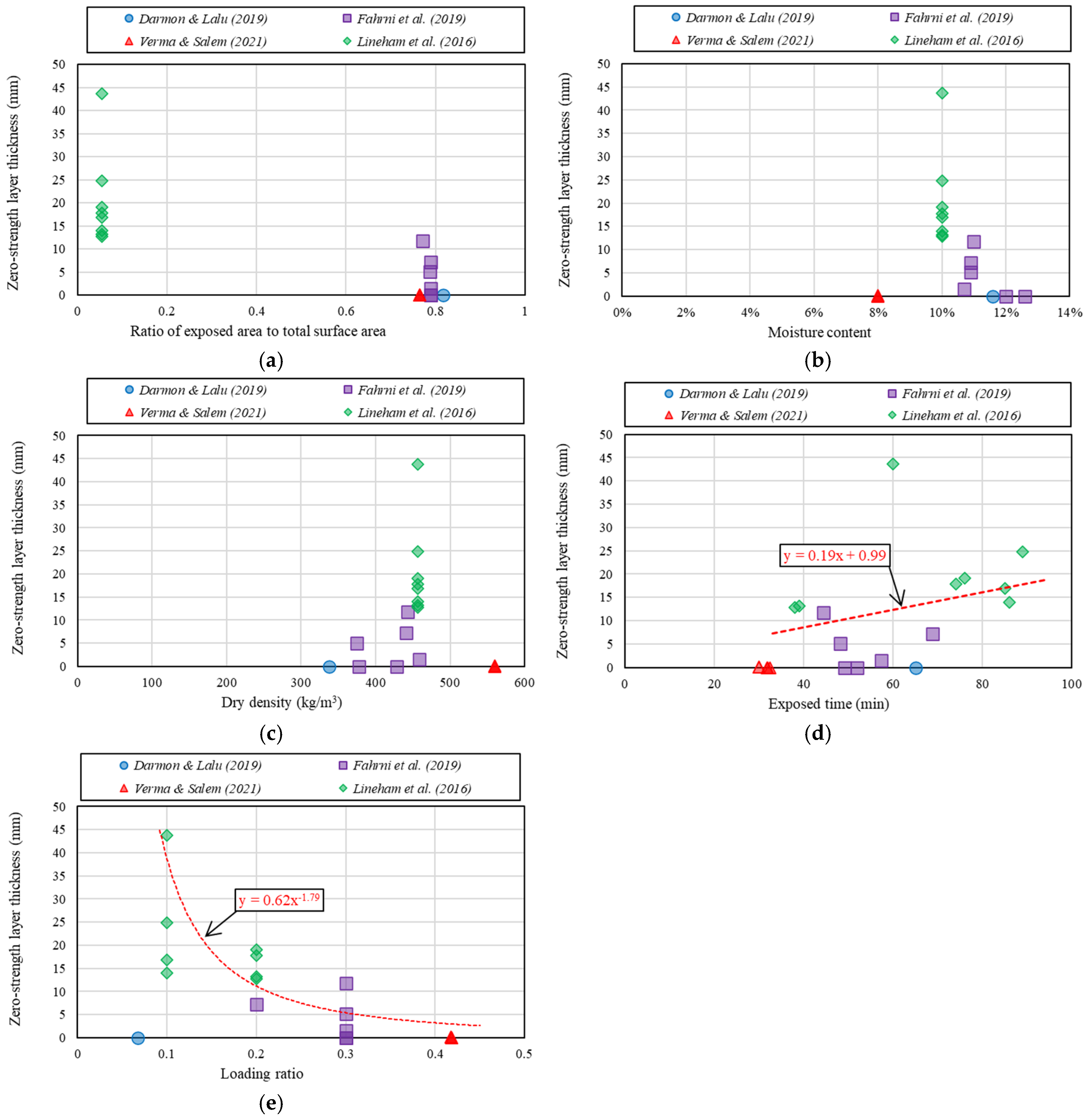
3.2. Analysis of Mass Timber Beam Fire Testing Data

A total of four mass timber beam fire experiments with 19 specimens were reviewed and analysed. Various key parameters such as moisture content and dry density of timber, exposed timber area, exposed time and sustained structural loading ratio were selected and plotted against the test results obtained from the mass timber beam fire testing to find if there is any correlation between the selected key parameters and the mass timber beam fire performance behaviour.
Mass timber beam charring rate is plotted against several key parameters and is presented in Figure 10. Figure 10a presents the charring rate plotted against the ratio of exposed timber area to total surface area of the beam. A constant charring rate of 0.65 mm/min, as specified by Eurocode 5 [43], is represented by a solid line, with dotted lines indicating the upper and lower bounds within 20% of the Eurocode 5 charring rate. The charring rates from experimental test data were also plotted against several key parameters, such as moisture content, dry density, exposed time and structural loading ratio (ratio of load applied during fire testing to the capacity of the beam at ambient temperature) which are depicted in Figure 10b–e, respectively. All plots demonstrate that the charring rates from experimental test data are within 20% of the Eurocode 5 charring rate, with a few exceptions.
Eurocode 5 [43] incorporates the reduced cross-section method (RCSM) for designing timber structures subjected to fire. This method considers reduced strength and stiffness beneath the charred surface by adding an additional layer, known as the zero-strength layer. This zero-strength layer is a crucial parameter in assessing the fire performance of timber structures. Figure 11 showed various plots of zero-strength layer thickness against several key parameters. Figure 11a–c illustrate the relationship between zero-strength layer thickness and the ratio of exposed timber area to total surface area, moisture content, and dry density of the beam, respectively. These plots show no correlation between the zero-strength layer thickness test data and these key parameters. However, Figure 11d,e indicate that “exposed time” and “loading ratio” are the key parameters that best correlate with zero-strength layer thickness. The zero-strength layer thickness increases linearly with exposed time, while a rapid decrease in zero-strength layer thickness is observed with an increased loading ratio.
Mass timber beam fire testing data obtained from the literature review are listed in Table A3 in Appendix A.

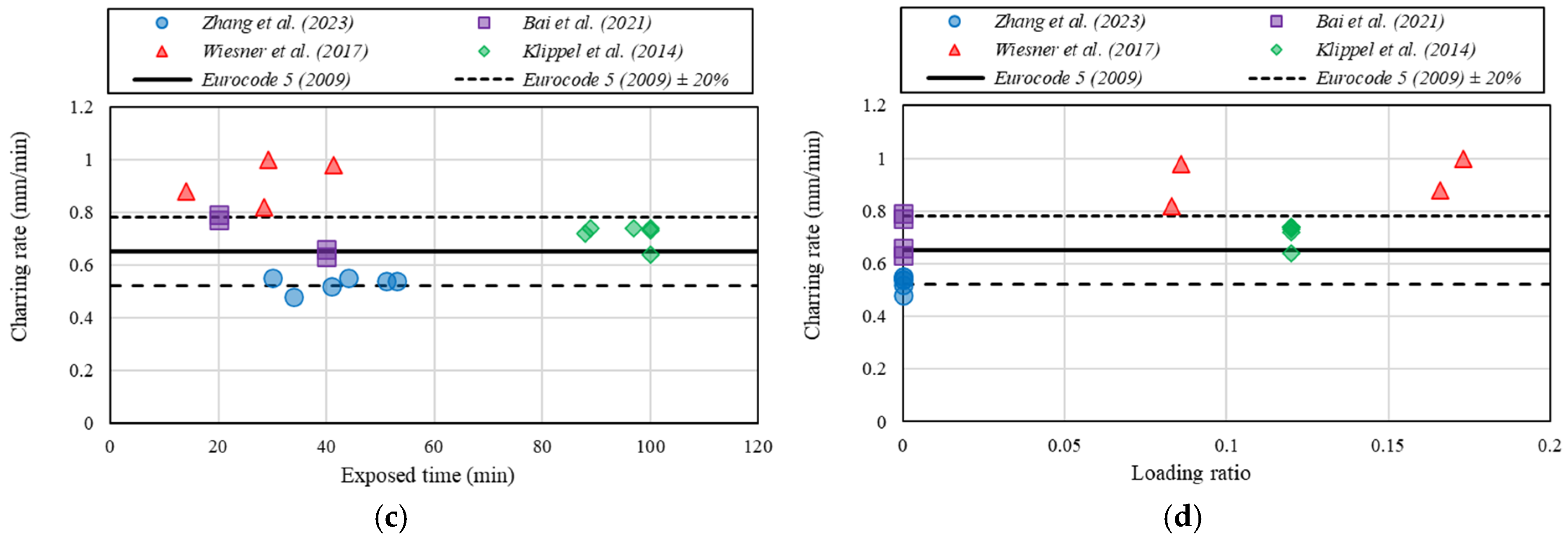
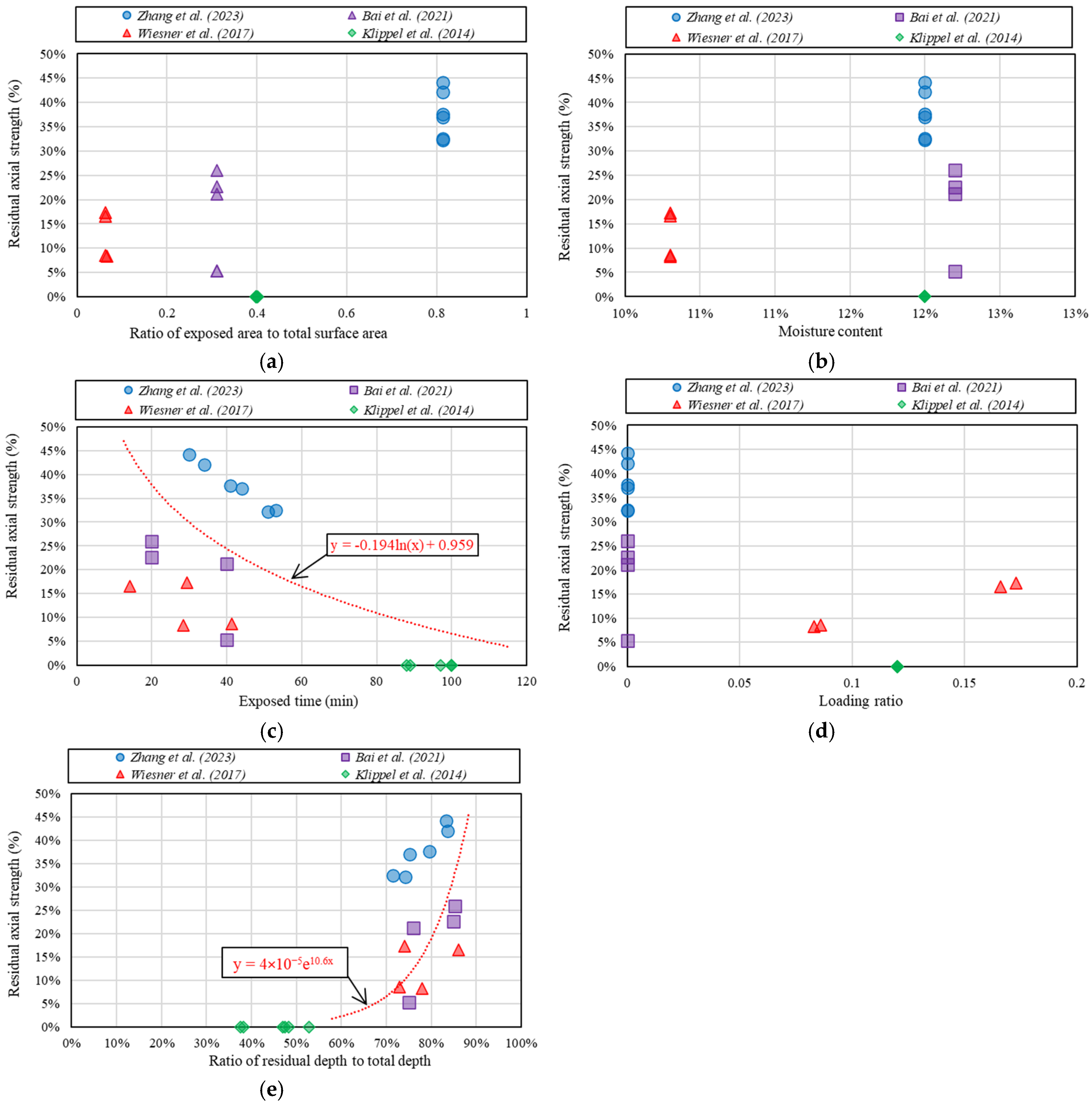
3.3. Analysis of Mass Timber Column/Wall Fire Testing Data

A total of four mass timber column/wall fire experiments with 20 specimens were reviewed and analysed. Various key parameters such as moisture content of timber, exposed timber area, exposed time and sustained structural loading ratio were selected and plotted against the test results obtained from the mass timber column/wall fire testing to find if there is any correlation between the selected key parameters and the mass timber column/wall fire performance behaviour.
Mass timber column/wall charring rate is plotted against several key parameters and is presented in Figure 12. Figure 12a presents the charring rate plotted against the ratio of exposed timber area to total surface area of the column/wall. A constant charring rate of 0.65 mm/min, as specified by Eurocode 5 [43], is represented by a solid line, with dotted lines indicating the upper and lower bounds within 20% of the Eurocode 5 charring rate. The charring rates from experimental test data were also plotted against several key parameters, such as moisture content, exposed time and structural loading ratio (ratio of load applied during fire testing to the capacity of the column/wall at ambient temperature), which are depicted in Figure 12b–d, respectively. All plots demonstrate that the charring rates from experimental test data are within 20% of the Eurocode 5 charring rate, with a few exceptions.
Mass timber column/wall residual axial strength (ratio of column/wall axial compression strength after fire testing to the axial compression strength at ambient temperature) is plotted against several key parameters and are presented in Figure 13. Figure 13a,b,d illustrate the relationship between residual axial strength and the ratio of exposed timber area to total surface area, moisture content and structural loading ratio, respectively. These plots show no correlation between the residual axial strength and these key parameters. However, Figure 13c,e indicate that “exposed time” and “ratio of residual depth to total depth” are the key parameters that best correlate with residual axial strength. The residual axial strength decreases rapidly with exposed time, while an exponential increase in residual axial strength is observed with an increased ratio of residual depth to total depth.
Mass timber column/wall fire testing data obtained from the literature review are listed in Table A4 in Appendix A.

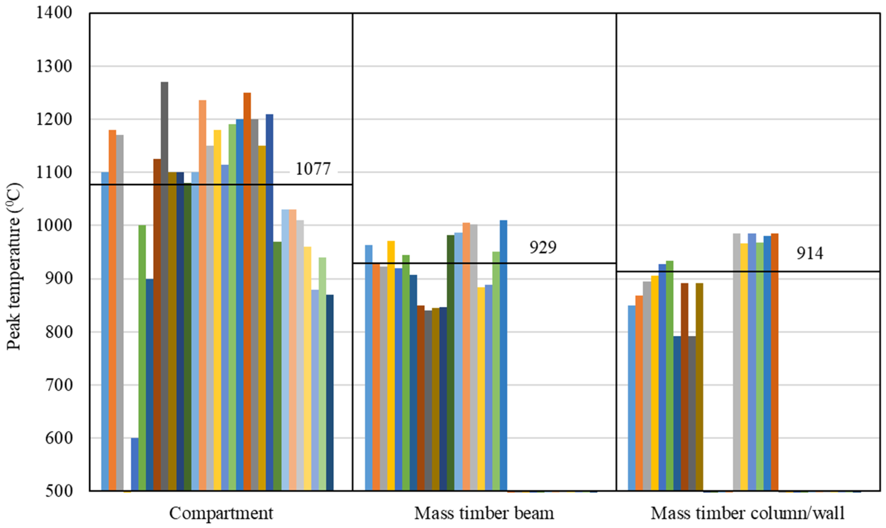
3.4. Comparison of Results from Compartment, Mass Timber Beam and Mass Timber Column/Wall Fire Testing

Unlike the mass timber beam and mass timber column/wall specimens, which were tested under standard fire conditions, compartment tests were conducted under non-standard and natural fire conditions. As such, the peak temperature of the compartment test specimen was scattered against exposed time (refer to Figure 14) compared to mass timber beam and mass timber column/wall test specimens. It is also observed from Figure 15 that the average peak temperature of the compartment specimen was significantly higher compared to the average peak temperature of the mass timber beam and mass timber column/wall specimens. The higher peak temperature of the compartment test specimen may be attributed to the uncontrolled fire conditions, compartment size, fuel load, openings/ventilation, exposed timber area, etc.
The average charring rate of the compartment test specimen was significantly (refer to Figure 16) higher (1.22 mm/min) compared to mass timber beam and mass timber column/wall test specimens. Furthermore, the charring rate of the compartment specimen was scattered (with a standard deviation of 0.69 mm/min) compared to less scatteredness in the mass timber beam (standard deviation of 0.12 mm/min) and mass timber column/wall (standard deviation of 0.15 mm/min) test specimens. The average charring rate of mass timber beams, and mass timber columns was found to be 0.60 mm/min and 0.70 mm/min, respectively, which are within ±10% of the charring rate stipulated in Eurocode 5 [43]. The variation of charring rate of mass timber beam and mass timber column/wall test specimen may be attributed to several key parameters such as moisture content, dry density, loading ratio, etc., whereas the scatteredness of charring rate of compartment test specimen may be attributed to uncontrolled fire conditions, compartment size, fuel load, openings/ventilation, exposed timber area, moisture content, dry density, loading ratio, etc.

4. Conclusions

This paper reviews and analyses the experimental fire testing data of eight compartments with 31 specimens, four mass timber beams with 19 specimens and four mass timber columns/walls with 20 specimens. Several key parameters, such as compartment opening factor, moisture content and dry density of timber, exposed timber area, exposed time and sustained structural loading ratio, were selected and plotted against the test results obtained from fire testing to find if there is any correlation between the selected key parameters and fire performance behaviour of mass timber structures.
Findings from this investigation are summarised below.
  • All compartment tests were conducted under non-standard and natural fire conditions, whereas mass timber beams and columns/walls were tested under standard fire conditions.
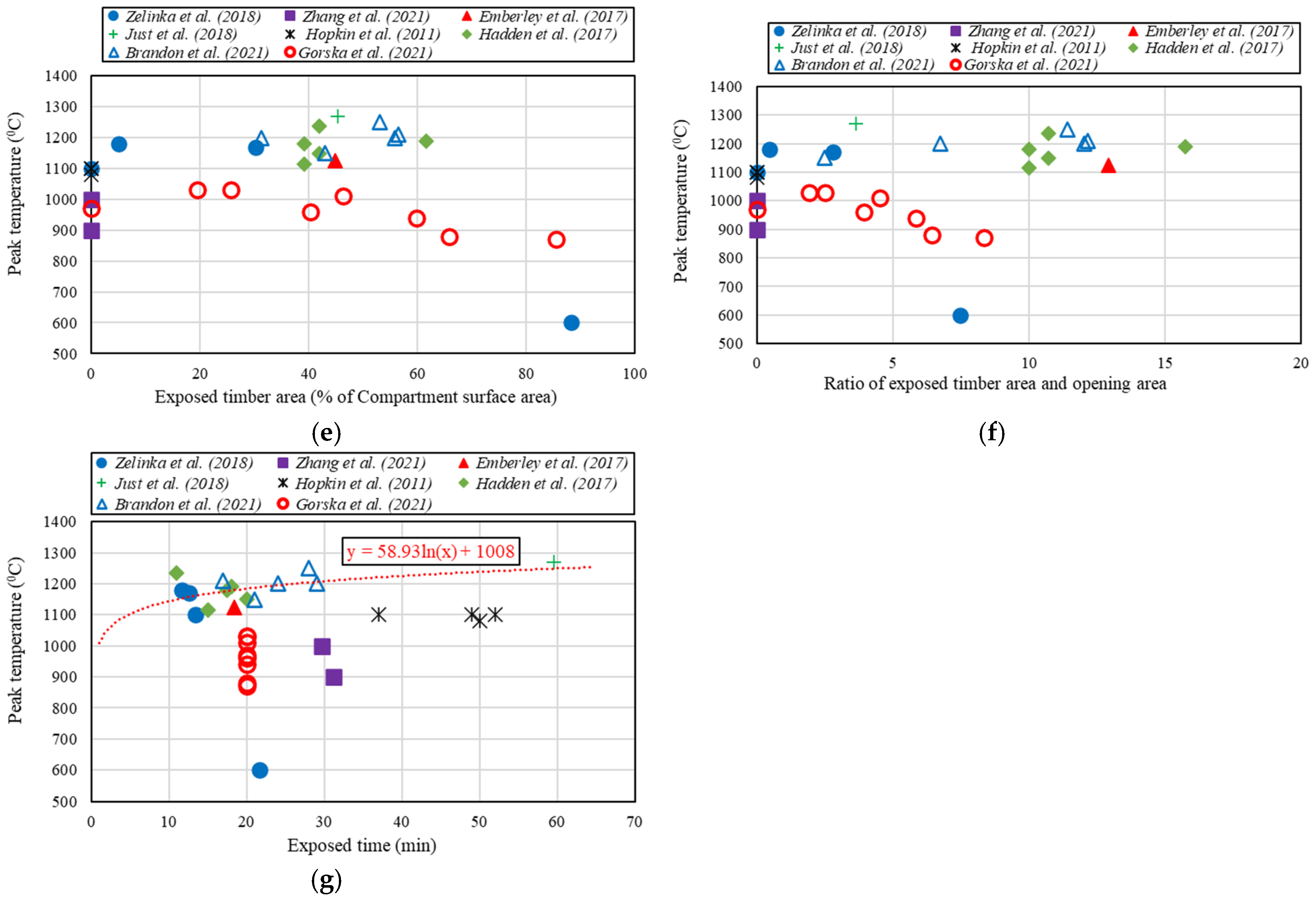
  • The compartment peak temperature was found to correlate with the key parameters “exposed timber area” and “exposed time”. The compartment peak temperature increases linearly with the exposed timber area and exposed time.
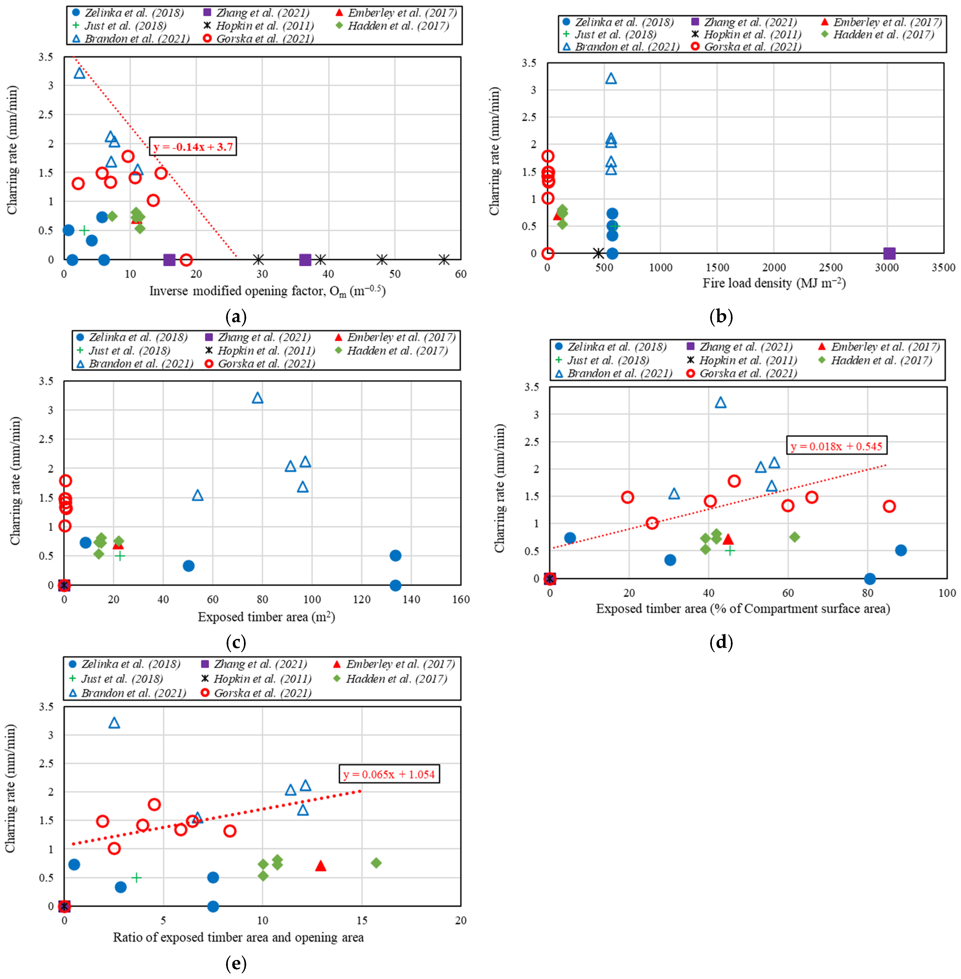
  • The compartment charring rate was found to correlate with the key parameters “inverse modified opening factor”, “exposed timber area as a percentage of compartment surface area” and “ratio of exposed timber area and opening area”.
  • The compartment reached its first peak temperature at approximately 2.4 times the initial growth phase time, and the compartment temperature decayed at approximately 4 times the initial growth phase time. However, the compartment first and second heat peak release rates occurred prior to reaching the compartment first and second peak temperatures, respectively.
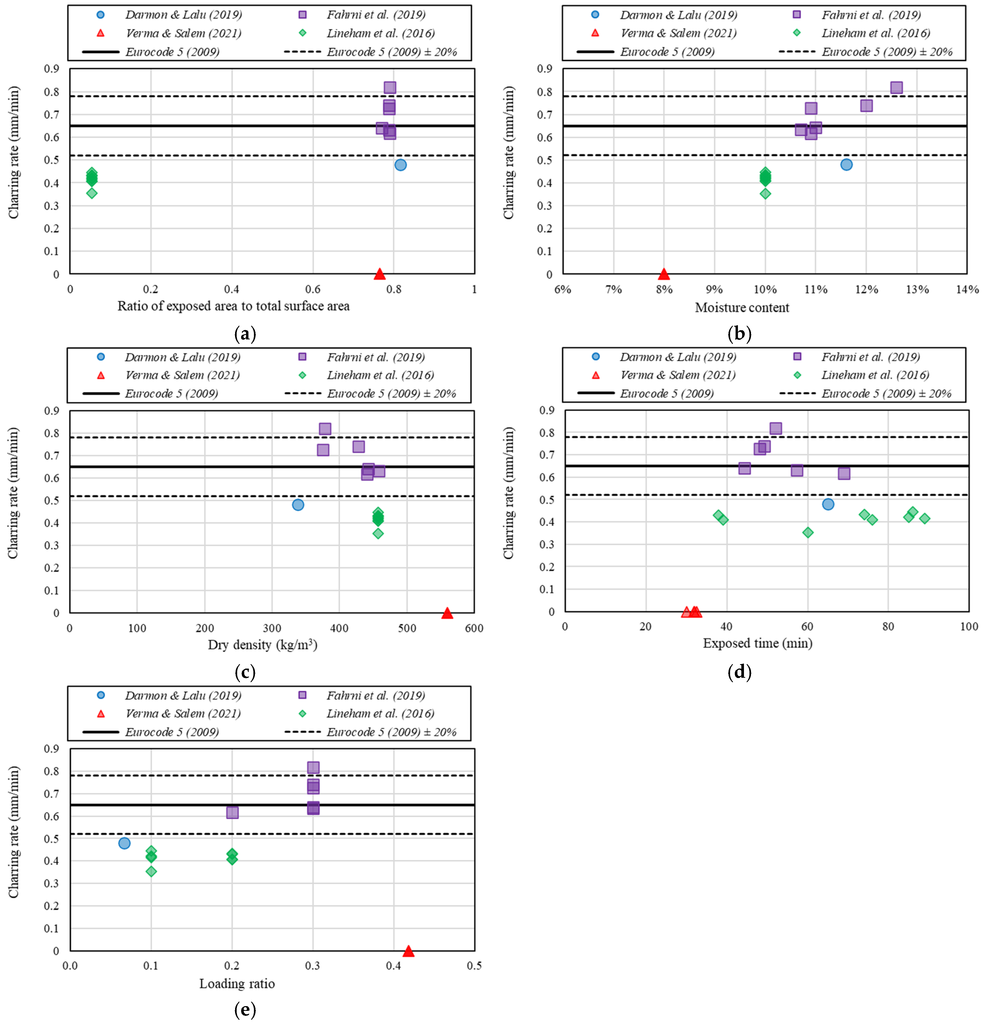
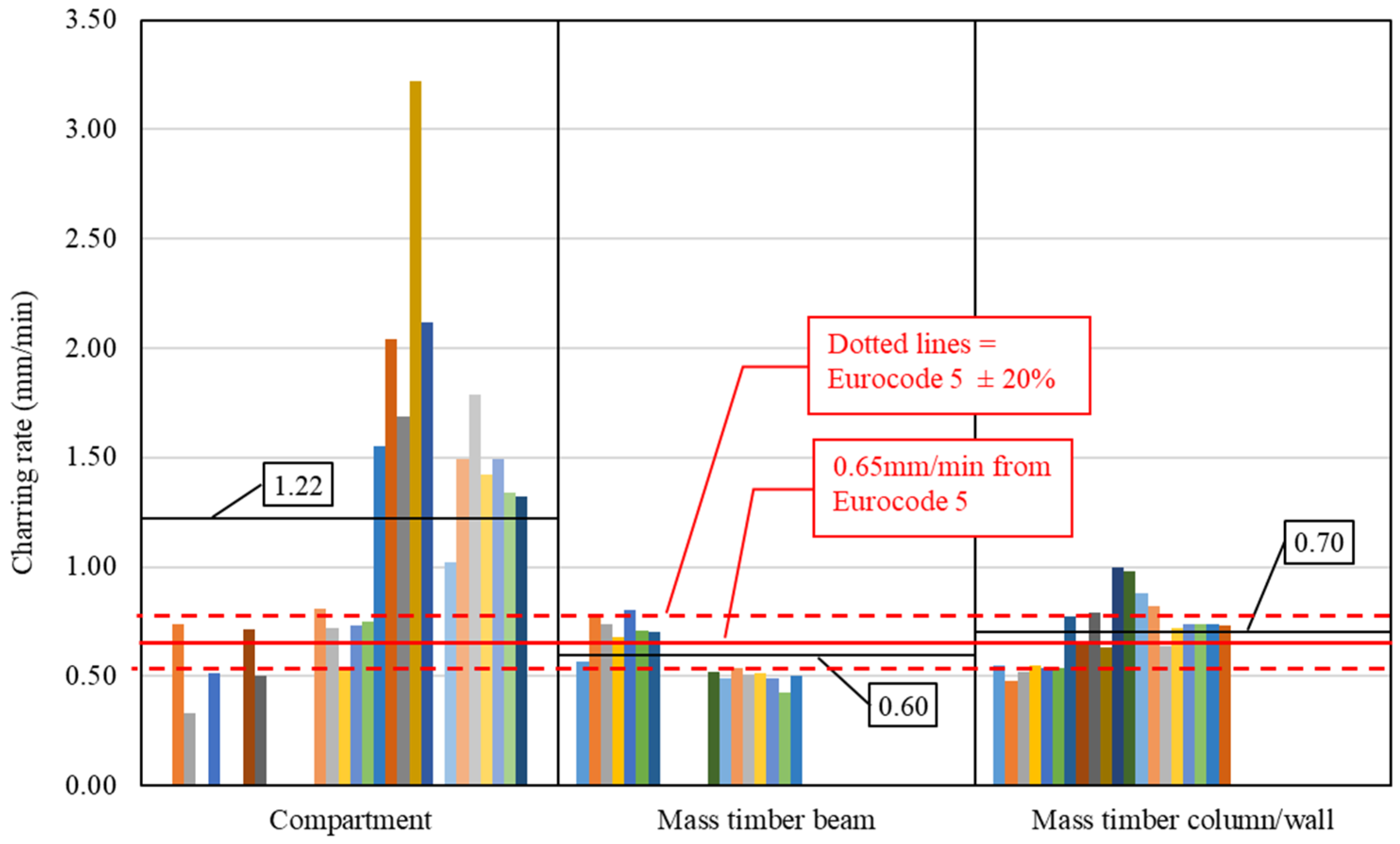
  • There were some fluctuations in the mass timber beam and column/wall charring rate plotted against several key parameters. However, the fluctuation was found to be within 20% of the charring rate specified in Eurocode 5.
  • The mass timber beam zero-strength layer thickness was found to correlate with the key parameters “exposed time” and “loading ratio”. The zero-strength layer thickness was found to be linearly increasing with the exposed time, unlike the constant zero-strength layer thickness of 7 mm specified in Eurocode 5.
  • The mass timber column/wall residual axial compression strength was found to correlate with the key parameters “exposed time” and “ratio of residual depth to total depth”. The residual axial strength decreases rapidly with fire exposed time, while an exponential increase in residual axial strength is observed with an increased ratio of residual depth to total depth.
  • The compartment average peak temperature was significantly higher compared to the mass timber beam and column/wall specimen.
  • The average charring rate of compartment test specimens was significantly higher (1.22 mm/min) compared to mass timber beam (0.60 mm/min) and mass timber column/wall (0.70 mm/min) test specimens. Furthermore, the charring rate of the compartment specimen was scattered (with a standard deviation of 0.69 mm/min) compared to less scatteredness in the mass timber beam (standard deviation of 0.12 mm/min) and mass timber column/wall (standard deviation of 0.15 mm/min) test specimens.
The development of mass timber structures for fire safety design requires further research in identifying the key parameters and their influence on fire dynamics behaviour. Critical key parameters, such as fire condition, exposed timber, exposed fire time, moisture content and density of timber, openings, structural loading, etc., significantly impact fire dynamics.

Author Contributions

Conceptualisation, S.M. and T.G.; methodology, S.M.; software, S.M.; formal analysis, S.M.; investigation, S.M.; data curation, S.M.; writing—original draft preparation, S.M.; writing—review and editing, S.M. and T.G.; visualisation, S.M. and T.G.; supervision, T.G. and P.M.; funding acquisition, T.G. and P.M. All authors have read and agreed to the published version of the manuscript.

Funding

This research was funded by the Australian Government Research Training Program Scholarship which is provided by the Australian Commonwealth Government and the University of Melbourne.

Data Availability Statement

Data are contained within the article.

Conflicts of Interest

The authors declare no conflicts of interest.

Appendix A

Table A1. Compartment experimental results of 31 test specimens from literature (Part 1).
AuthorCompartment Floor Area (m2)Exposed Timber Area (m2)Opening Area (m2) Inverse Modified Opening Factor (m−0.5)Fire Load Density (MJm−2)Average Charring Rate (mm/min)Peak
Temperature (°C)
Zelinka et al. [28]83.540.0017.865.94570N/A1100
83.548.3617.865.655700.741180
83.5450.0917.864.155700.331170
83.54133.6317.861.16570N/AN/A
83.54133.6317.860.635700.51600
Zhang et al. [29]8.640.001.0036.443015N/A1000
8.640.001.6015.843015N/A900
Emberley et al. [30]12.2521.701.6810.951000.711125
Just et al. [31]15.7522.506.203.016000.501270
Hopkin et al. [32]12.000.001.5029.40450N/A1100
12.000.001.5038.73450N/A1100
12.000.001.5048.07450N/A1080
12.000.001.5057.40450N/A1100
Hadden et al. [33]7.4015.001.4010.911320.811236
7.4015.001.4010.911320.721150
7.4014.001.4011.441320.531180
7.4014.001.4011.441320.731114
7.4022.001.407.221320.751190
Brandon et al. [34]47.9553.808.0011.085601.551200
47.9591.208.007.575602.041250
47.9596.208.007.115601.691200
47.9577.9031.202.285603.221150
47.9597.208.007.015602.121210
Gorska et al. [26]0.250.000.0818.43N/AN/A970
0.250.210.0813.45N/A1.021030
0.250.160.0814.56N/A1.491030
0.250.380.089.58N/A1.791010
0.250.330.0810.69N/A1.42960
0.250.540.085.71N/A1.49880
0.250.490.087.00N/A1.34940
0.250.700.082.03N/A1.32870
Table A2. Compartment experimental results of 31 test specimens from literature (Part 2).
AuthorFire Development (min)
Initial GrowthFirst Peak HRRSecond Peak HRRFirst Peak TemperatureSecond Peak TemperatureDecay *
Zelinka et al. [28]13.014.518.913.5N/AN/A
11.013.019.111.723.831.2
12.0N/A20.612.627.236.0
N/ANegligibleN/AN/AN/AN/A
3.917.923.29.921.723.5
Zhang et al. [29]21.8N/AN/A23.729.731.2
20.8N/AN/A22.031.235.5
Emberley et al. [30]11.8N/AN/A18.4N/A21.8
Just et al. [31]23.0N/AN/A59.5121.0136.0
Hopkin et al. [32]14.0N/AN/A52.0N/A64.0
12.0N/AN/A37.0N/A50.0
17.0N/AN/A50.0N/A69.0
9.0N/AN/A49.0N/A52.0
Hadden et al. [33]4.66.3N/A11.0N/A21.0
5.112.5N/A20.058.0N/A
8.610.5N/A17.5N/A19.0
4.27.5N/A15.022.0N/A
5.47.0N/A18.0N/AN/A
Brandon et al. [34]14.012.0N/A24.0N/A37.0
8.017.0N/A28.0N/A42.0
12.014.0N/A29.0N/A47.0
17.014.0N/A21.0N/A28.0
4.015.0N/A17.0N/A46.0
Gorska et al. [26]10.0N/AN/A20.0N/A35.0
10.0N/AN/A20.0N/A35.0
* Decay—Refer to Figure 8.
Table A3. Mass timber beam experimental results of 19 test specimens from literature.
AuthorTotal Surface Area (m2)Exposed Area (m2)Moisture Content (%)Dry Density (kg/m3)Exposed Time (min)Loading Ratio (%)Peak Temperature (°C)Charring Rate (mm/min)Zero-Strength Layer Thickness (mm)
Darmon & Lalu [39]3.562.9011.6%33865.06.7%9630.57N/A
Fahrni et al. [40]3.282.5912.6%37852.030.0%9300.78N/A
3.192.5112.0%42849.330.0%9220.74N/A
3.302.6010.9%44168.920.0%9720.687.2
3.282.5810.9%37548.130.0%9190.805.1
3.262.5710.7%45857.330.0%9450.711.5
2.782.1411.0%44344.430.0%9070.7011.8
Verma & Salem [41]3.552.728.0%56032.541.8%850N/A0.0
3.552.728.0%56030.041.8%840N/A0.0
3.552.728.0%56031.841.8%845N/A0.0
3.552.728.0%56032.041.8%846N/A0.0
Lineham et al. [42]1.660.0910.0%45774.020.0%9820.5217.8
1.660.0910.0%45776.020.0%9860.4919.1
1.660.0910.0%45786.010.0%10050.5314.0
1.660.0910.0%45785.010.0%10030.5116.9
1.660.0910.0%45738.020.0%8840.5212.8
1.660.0910.0%45739.020.0%8880.4913.2
1.660.0910.0%45760.010.0%9520.4343.7
1.660.0910.0%45789.010.0%10100.5024.8
Table A4. Mass timber column/wall results of 20 test specimens from literature.
AuthorTotal Surface Area (m2)Exposed Area (m2)Moisture Content (%)Exposed Time (min)Loading Ratio (%)Peak Temperature (°C)Charring Rate (mm/min)Residual Axial Strength (%)Ratio of Residual Depth to Total Depth (%)
Zhang et al. [45]1.281.0412.0%30.00.0%8500.5544%83%
1.281.0412.0%34.00.0%8680.4842%84%
1.281.0412.0%41.00.0%8960.5238%80%
1.281.0412.0%44.00.0%9060.5537%75%
1.281.0412.0%51.00.0%9280.5432%74%
1.281.0412.0%53.00.0%9330.5433%71%
Bai et al. [46]3.241.0112.2%20.00.0%7920.7726%85%
3.241.0112.2%40.00.0%8920.665%75%
3.241.0112.2%20.00.0%7920.7923%85%
3.241.0112.2%40.00.0%8920.6321%76%
Wiesner et al. [47]1.420.0910.3%29.317.3%N/A1.0017%74%
1.420.0910.3%41.38.6%N/A0.989%73%
1.420.0910.3%14.116.6%N/A0.8817%86%
1.360.0910.3%28.48.3%N/A0.828%78%
Kippel et al. [48]3.591.4412.0%100.012.0%9850.640%38%
3.591.4412.0%88.012.0%9670.720%38%
4.981.9812.0%100.012.0%9850.740%47%
4.981.9812.0%89.012.0%9680.740%53%
4.981.9812.0%97.012.0%9800.740%47%
4.981.9812.0%10012.0%9850.730%48%

References

  1. Harte, A.M. Mass timber–the emergence of a modern construction material. J. Struct. Integr. Maint. 2017, 2, 121–132. [Google Scholar] [CrossRef]
  2. Evison, D.C.; Kremer, P.D.; Guiver, J. Mass timber construction in Australia and New Zealand-status, and economic and environmental influences on adoption. Wood Fiber Sci. 2018, 50, 128–138. [Google Scholar] [CrossRef]
  3. Waugh Thistleton Architects and Weiss Insights. Available online: https://issuu.com/waughthistleton (accessed on 11 January 2025).
  4. Karacabeyli, E.; Douglas, B. CLT Handbook: Cross-Laminated Timber; FP Innovations: Pointe-Claire, QC, Canada, 2013. [Google Scholar]
  5. Kuilen, J.W.G.V.D.; Ceccotti, A.; Xia, Z.; He, M. Very Tall Wooden Buildings with Cross Laminated Timber. Procedia Eng. 2011, 14, 1621–1628. [Google Scholar] [CrossRef]
  6. Ong, C.B. Glue-laminated timber (Glulam). In Wood Composites; Woodhead Publishing: Sawston, UK, 2015; pp. 123–140. [Google Scholar] [CrossRef]
  7. Binational Softwood Lumber Council. Nail-Laminated Timber: US Design & Construction Guide; Binational Softwood Lumber Council: Surrey, BC, Canada, 2017. [Google Scholar]
  8. Sotayo, A.; Bradley, D.; Bather, M.; Sareh, P.; Oudjene, M.; El-Houjeyri, I.; Harte, A.M.; Mehra, S.; O′Ceallaigh, C.; Haller, P. Review of state of the art of dowel laminated timber members and densified wood materials as sustainable engineered wood products for construction and building applications. Dev. Built Environ. 2020, 1, 100004. [Google Scholar] [CrossRef]
  9. Stark, N.; Cai, Z.; Carll, C. Wood-Based Composite Materials-Panel Products, Glued-Laminated Timber, Structural Composite Lumber, and Wood-Nonwood Composite Materials. In Wood Handbook: Wood as an Engineering Material, FPL-GTR-282; U.S. Department of Agriculture: Washington, DC, USA, 2010. [Google Scholar]
  10. John, S.; Nebel, B.; Perez, N.; Buchanan, A. Environmental Impacts of Multi-Storey Buildings Using Different Construction Materials; New Zealand Ministry of Agriculture and Forestry: Christchurch, New Zealand, 2009.
  11. Pettersson, C. Fire Safety in Timber Buildings—A Review of Existing Knowledge, Brandforsk. 2020. Available online: https://www.brandforsk.se/wp-content/uploads/2020/11/Brandforsk_Report_Fire-Safety-in-Timber-Buildings-1.pdf (accessed on 11 January 2025).
  12. Hopkin, D.J.; Spearpoint, M. A calculation method for flame extension from partially exposed mass timber enclosures. In Proceedings of the Applications of Structural Fire Engineering, Ljubljana, Sloveni, 9–11 June 2021. [Google Scholar]
  13. Construction News, Notts TV Nottingham University Chemistry Building Destroyed in Fire–Video. Available online: https://www.theguardian.com/uk-news/video/2014/sep/13/nottingham-university-chemistry-building-destroyed-fire-video (accessed on 12 February 2025).
  14. The Building (Amendment) Regulations. UK Statutory Instruments 2018 No. 1230, Building and Buildings, England. 2018. Available online: https://www.legislation.gov.uk/uksi/2018/1230/contents/made (accessed on 11 January 2025).
  15. Law, A.; Butterworth, N. Prescription in English fire regulation: Treatment, cure or placebo? Proc. Inst. Civ. Eng. Forensic Eng. 2019, 172, 61–68. [Google Scholar] [CrossRef]
  16. Abed, J.; Rayburg, S.; Rodwell, J.; Neave, M. A Review of the Performance and Benefits of Mass Timber as an Alternative to Concrete and Steel for Improving the Sustainability of Structures. Sustainability 2022, 14, 5570. [Google Scholar] [CrossRef]
  17. Chirag Enterprises Laminated Veneer Lumber LVL Board. Available online: https://www.indiamart.com/proddetail/laminated-veneer-lumber-19724343155.html (accessed on 15 March 2025).
  18. CWC. Laminate Veneer Lumber—The Canadian Wood Council—CWC. Available online: https://cwc.ca/wp-content/uploads/2020/06/105.1_AWC-CWC_EPD_North-American-Laminated-Veneer-Lumber-1.pdf (accessed on 15 March 2025).
  19. CWC. Laminated Strand Lumber—The Canadian Wood Council—CWC. Available online: https://cwc.ca/articles/laminated-strand-lumber/ (accessed on 15 March 2025).
  20. Naturally Wood. What Is Laminated Strand Lumber (LSL)?—Naturally: Wood. Available online: https://www.naturallywood.com/products/laminated-strand-lumber/ (accessed on 15 March 2025).
  21. Mitchell, H.; Kotsovinos, P.; Richter, F.; Thomson, D.; Barber, D.; Rein, G. Review of fire experiments in mass timber compartments: Current understanding, limitations, and research gaps. Fire Mater. 2022, 47, 415–432. [Google Scholar] [CrossRef]
  22. ASTM E119; Standard test Methods for Fire Tests of Building Construction and Materials. American Society for Testing and Materials: West Conshohocken, PA, USA, 2012.
  23. ISO 834-1; Fire-Resistance Tests—Elements of Building Construction—Part 1: General Requirements. International Organization for Standardization: Geneva, Switzerland, 1999.
  24. CAN/ULC-S101; Standard Methods of Fire Endurance Tests of Building Construction and Material. Underwriters Laboratories of Canada: Toronto, ON, Cannada, 2014.
  25. Thomas, P.J.; Heselden, A.J. Fully Developed Fires in Single Compartments; CIB Report; Fire Research Station: Tokyo, Japan, 1972. [Google Scholar]
  26. Gorska, C.; Hidalgo, J.P.; Torero, J.L. Fire dynamics in mass timber compartments. Fire Saf. J. 2021, 120, 103098. [Google Scholar] [CrossRef]
  27. VOSviewer, Version 1.6.20; Centre for Science and Technology Studies, Leiden University: Leiden, The Netherlands, 2023.
  28. Zelinka, S.L.; Hasburgh, L.E.; Bourne, K.J.; Tucholski, D.R.; Ouellette, J.P.; Kochkin, V. Compartment Fire Testing of a Two-Story Mass Timber Building. 2018. Available online: https://awc.org/wp-content/uploads/2022/02/fpl_gtr247.pdf (accessed on 9 September 2023).
  29. Zhang, Y.; Yang, X.; Luo, Y.; Gao, Y.; Liu, H.; Li, T. Experimental study of compartment fire development and ejected flame thermal behavior for a large-scale light timber frame construction. Case Stud. Therm. Eng. 2021, 27, 101133. [Google Scholar] [CrossRef]
  30. Emberley, R.; Putynska, C.G.; Bolanos, A.; Lucherini, A.; Solarte, A.; Soriguer, D.; Gonzalez, M.G.; Humphreys, K.; Hidalgo, J.P.; Maluk, C.; et al. Description of small and large-scale cross laminated timber fire tests. Fire Saf. J. 2017, 91, 327–335. [Google Scholar] [CrossRef]
  31. Just, A.; Brandon, D.; Mager, K.N.; Lange, D.; Pukk, R. CLT compartment fire. In Proceedings of the 2018 World Conference on Timber Engineering, Seoul, Republic of Korea, 20–23 August 2018. [Google Scholar]
  32. Hopkin, D.J.; Lennon, T.; El-Rimawi, J.; Silberschmidt, V. Full-scale natural fire tests on gypsum lined structural insulated panel (SIP) and engineered floor joist assemblies. Fire Saf. J. 2011, 46, 528–542. [Google Scholar] [CrossRef]
  33. Hadden, R.M.; Bartlett, A.I.; Hidalgo, J.P.; Santamaria, S.; Wiesner, F.; Bisby, L.A.; Deeny, S.; Lane, B. Effects of exposed cross laminated timber on compartment fire dynamics. Fire Saf. J. 2017, 91, 480–489. [Google Scholar] [CrossRef]
  34. Brandon, D.; Sjöström, J.; Temple, A.; Hallberg, E.; Kahl, F. Fire Safe Implementation of Visible Mass Timber in Tall Buildings–Compartment Fire Testing; Uppsala University: Uppsala, Sweden, 2021; p. 223. ISBN 978-91-89385-26-9. [Google Scholar]
  35. Frangi, A.; Fontana, M. Fire Performance of Timber Structures Under Natural Fire Conditions. Fire Saf. Sci. 2005, 8, 279–290. [Google Scholar] [CrossRef]
  36. Jessop, D.; Abu, A.; Wade, C.; Spearpoint, M.; Gerlich, H. Performance of a light timber-framed compartment in natural fire subjected to lateral load. Fire Mater. 2019, 73, 175–188. [Google Scholar] [CrossRef]
  37. Babrauskas, V. Ignition of Wood: A Review of the State of the Art. J. Fire Prot. Eng. 2002, 12, 163–189. [Google Scholar] [CrossRef]
  38. Drysdale, D. An Introduction to Fire Dynamics, 3rd ed.; John Wiley & Sons: Hoboken, NJ, USA, 2011. [Google Scholar]
  39. Dârmon, R.; Lalu, O. The fire performance of Cross Laminated Timber beams. Procedia Manuf. 2019, 32, 121–128. [Google Scholar] [CrossRef]
  40. Fahrni, R.; Klippel, M.; Just, A.; Ollino, A.; Frangi, A. Fire tests on glued-laminated timber beams with specific local material properties. Fire Saf. J. 2019, 107, 161–169. [Google Scholar] [CrossRef]
  41. Verma, N.; Salem, O. Comparitive study on the flexural behaviour of glulam built-up beams based on ambient and standard fire tests. Eng. Struct. 2021, 233, 111759. [Google Scholar] [CrossRef]
  42. Lineham, S.A.; Thomson, D.; Bartlett, A.I.; Bisby, L.A.; Hadden, R.M. Structural response of fire-exposed cross-laminated timber beams under sustained loads. Fire Saf. J. 2016, 85, 23–34. [Google Scholar] [CrossRef]
  43. EN 1995-1-2; Eurocode 5 Design of Timber Structures, Part 1–2: General Structural Fire Design. CEN: Brussels, Belgium, 2009.
  44. Schaffer, E.; Marx, C.; Bender, D.; Woeste, F. Strength Validation and Fire Endurance of Glued-Laminated Timber Beams; U.S. Department of Agriculture, Forest Service, Forest Products Laboratory: Madison, WI, USA, 1986.
  45. Zhang, Y.; Zhi, W.; Zhang, X.; Ni, W.; Xu, C.; Xu, Y.; Wang, L. Experimental and numerical study on the validity of the energy-based time equivalent method for evaluating the fire resistance of timber components exposed to travelling fires. J. Build. Eng. 2023, 76, 107169. [Google Scholar] [CrossRef]
  46. Bai, Y.; Zhang, J.; Shen, H. Residual compressive load-carrying capacity of cross-laminated timber walls after exposed to one-side fire. J. Build. Eng. 2021, 34, 101931. [Google Scholar] [CrossRef]
  47. Wiesner, F.; Randmael, F.; Wan, W.; Bisby, L.; Hadden, R.M. Structural response of cross-laminated timber compression elements exposed to fire. Fire Saf. J. 2017, 91, 56–67. [Google Scholar] [CrossRef]
  48. Kippel, M.; Leyder, C.; Frangi, A.; Fontana, M. Fire Tests on Loaded Cross-laminated Timber Wall and Floor Elements. Fire Saf. Sci. 2014, 11, 626–639. [Google Scholar] [CrossRef]
  49. Blagojevic, M.; Pesic, D. A new curve for temperature-time relationship in compartment fire. Therm. Sci. 2011, 15, 339–352. [Google Scholar] [CrossRef]
Figure 1. Diagram illustrating the manufacturing process of engineered or mass timber elements [3].
Jcs 09 00290 g001
Figure 5. Visualisation network of co-occurrences of keywords generated by VOSviewer.
Jcs 09 00290 g005
Figure 6. Compartment peak temperature vs. several key parameters: (a) peak temperature vs. inverse modified opening factor [25,26,28,29,30,31,32,33,34]; (b) peak temperature vs. fire load density [26,28,29,30,31,32,33,34]; (c) peak temperature vs. exposed timber area [26,28,29,30,31,32,33,34]; (d) peak temperature vs. exposed timber area with line of best fit [26,28,29,30,31,32,33,34]; (e) peak temperature vs. exposed timber area as a percentage of compartment surface area [26,28,29,30,31,32,33,34]; (f) peak temperature vs. ratio of exposed timber area and opening area [26,28,29,30,31,32,33,34]; (g) peak temperature vs. time [26,28,29,30,31,32,33,34].
Jcs 09 00290 g006aJcs 09 00290 g006b
Figure 7. Compartment charring rate vs. several key parameters: (a) charring rate vs. inverse modified opening factor [26,28,29,30,31,32,33,34]; (b) charring rate vs. fire load density [26,28,29,30,31,32,33,34]; (c) charring rate vs. exposed timber area [26,28,29,30,31,32,33,34]; (d) charring rate vs. exposed timber area as a percentage of compartment surface area [26,28,29,30,31,32,33,34]; (e) charring rate vs. ratio of exposed timber area and opening area [26,28,29,30,31,32,33,34].
Jcs 09 00290 g007
Figure 8. Temperature-time curve [49].
Jcs 09 00290 g008
Figure 9. Compartment fire development phases normalised to the initial growth phase.
Jcs 09 00290 g009
Figure 10. Mass timber beam charring rate vs. several key parameters: (a) charring rate vs. ratio of exposed area to total surface area of timber beam [39,40,41,42,43]; (b) charring rate vs. moisture content [39,40,41,42,43]; (c) charring rate vs. dry density [39,40,41,42,43]; (d) charring rate vs. exposed time [39,40,41,42,43]; (e) charring rate vs. loading ratio [39,40,41,42,43].
Jcs 09 00290 g010
Figure 11. Mass timber beam zero-strength layer thickness vs. several key parameters: (a) zero-strength layer thickness vs. ratio of exposed area to total surface area of timber beam [39,40,41,42]; (b) zero-strength layer thickness vs. moisture content [39,40,41,42]; (c) zero-strength layer thickness vs. dry density [39,40,41,42]; (d) zero-strength layer thickness vs. exposed time [39,40,41,42]; (e) zero-strength layer thickness vs. loading ratio [39,40,41,42].
Jcs 09 00290 g011
Figure 12. Mass timber column/wall charring rate vs. several key parameters: (a) charring rate vs. ratio of exposed area to total surface area of timber column/wall [43,45,46,47,48]; (b) charring rate vs. moisture content [43,45,46,47,48]; (c) charring rate vs. exposed time [43,45,46,47,48]; (d) charring rate vs. loading ratio [43,45,46,47,48].
Jcs 09 00290 g012aJcs 09 00290 g012b
Figure 13. Mass timber column/wall residual axial strength vs. several key parameters: (a) residual axial strength vs. ratio of exposed area to total surface area of timber column/wall [45,46,47,48]; (b) residual axial strength vs. moisture content [45,46,47,48]; (c) residual axial strength vs. exposed time [45,46,47,48]; (d) residual axial strength vs. loading ratio [45,46,47,48]; (e) residual axial strength vs. ratio of residual depth to total depth [45,46,47,48].
Jcs 09 00290 g013
Figure 14. Peak temperature vs. time of different structures test specimens [22,23,24].
Jcs 09 00290 g014
Figure 15. Peak temperature of different structures test specimens.
Jcs 09 00290 g015
Figure 16. Charring rate of different structures test specimens.
Jcs 09 00290 g016
Disclaimer/Publisher’s Note: The statements, opinions and data contained in all publications are solely those of the individual author(s) and contributor(s) and not of MDPI and/or the editor(s). MDPI and/or the editor(s) disclaim responsibility for any injury to people or property resulting from any ideas, methods, instructions or products referred to in the content.

