Article

Experimental Study on the Effect of Impactor Hardness and Shape on the Impact Response of Composite Panels

1
Department of Mechanical Engineering, Imperial College London, London SW7 2AZ, UK
2
School of Engineering and Materials Science, Queen Mary University of London, London E1 4NS, UK
*
Authors to whom correspondence should be addressed.
These authors contributed equally to this work.
J. Compos. Sci. 2025, 9(5), 230; https://doi.org/10.3390/jcs9050230
Submission received: 28 February 2025 / Revised: 23 April 2025 / Accepted: 29 April 2025 / Published: 2 May 2025

Abstract

:
In recent decades, the application of composite materials in aerostructures has significantly increased, with modern commercial aircraft progressively replacing aluminum alloys with composite components. This shift is exemplified by comparing the material compositions of the Boeing 777 and the Boeing 787 (Dreamliner). The Boeing 777 incorporates approximately 50% aluminum alloy and 12% composite materials, whereas the Dreamliner reverses this ratio, utilizing around 50% composites and 12% aluminum alloy. While metals remain advantageous due to their availability and ease of machining, composites offer greater potential for property tailoring to meet specific performance requirements. They also provide superior strength-to-weight ratios and enhanced resistance to corrosion and fatigue. To ensure the reliability of composites in aerospace applications, comprehensive testing under various loading conditions, particularly impact, is essential. Impacts were performed on quasi-isotropic (QIT) carbon-fiber reinforced epoxy panels with stainless steel, round-nosed and flat-ended impactors with rubber discs of 1-, 1.5- and 2 mm thickness, adhered to the flat-ended impactor to simulate the transition between hard and soft impact loading conditions. QIT composite panels were tested in this research employing similar lay-ups often being implemented in aircraft wings and other structures. The rubber discs were applied in the flat-ended impactor case but not for the round-nosed impactor due to the limited adhesion between the rubber and the rounded stainless-steel surface. Impact energies of 7.5, 15 and 30 J were investigated, and the performance of the panels was evaluated using force-time and force-displacement data alongside post-impact ultrasonic C-scan imaging to assess the damaged area. Damage was observed at all three energy values for the round-nosed impacts but only at the highest impact energy when using the flat-ended impactor, leading to the hardness study with adhered rubber discs being performed at 30 J. The most noticeable difference with the addition of rubber discs was the reduction in the damage in the plies nearest the top (impacted) surface. This suggests that the rubber reduces the severity of the impact, but increasing the thickness of the rubber from 1 to 2 mm does not notably increase this effect. Indentation clearly plays a significant role in promoting delamination at low-impact energies for the round-nosed impactors.

1. Introduction

Aircraft structures experience diverse impact events during operation [1], ranging from low-velocity hard impacts such as tool drops to high-velocity soft impacts like bird strikes [2,3]. These scenarios represent distinct mechanical interactions with markedly different damage characteristics. The severity of impact damage is further influenced by the geometry of the impactor. Blunter impactors distribute force over a broader surface area, typically resulting in reduced damage, whereas sharper impactors localize energy, often causing concentrated indentation damage. Accordingly, it becomes essential to establish clear criteria to differentiate between hard and soft impacts and to categorize them accurately for predictive and diagnostic purposes. Moreover, the mechanisms of damage initiation and progression in CFRP panels differ significantly between hard and soft impact conditions. Another critical consideration is the shape of the impactor, as it significantly influences damage behavior—specifically, how CFRP panels respond to sharper impactors in contrast to blunter ones [4,5,6,7].
The classification of impacts as hard or soft has been addressed by several researchers. Yankelevsky characterized hard impacts as those where the impacting object undergoes minimal deformation compared to the target structure, typically sustaining no damage itself [8]. In contrast, Koechlin et al. suggested a different classification taking into account the hardness of an impactor and its relationship to impactor material and velocity and the degree to which the impact is elastic or plastic. At low velocities, an impact is considered soft if the projectile is damaged while the target remains intact; a hard impact is one where penetration occurs [9]. However, often, the impact on CFRP material does not result in penetration. Therefore, it is reasonable to define hard impacts as those in which the impactor remains undeformed—such as tool drops or runway debris—while soft impacts involve deformable impactors, like hailstones or birds.
Impact testing of pristine CFRP panels most commonly involves hard, low-velocity impacts, with numerous studies reporting such results [10,11,12,13,14,15,16,17,18,19]. Caprino et al. reported that penetration of CFRP panels subjected to low-velocity hard impacts could occur at energy levels as low as 1 J, primarily influenced by parameters such as total fiber volume, laminate thickness, and impactor diameter [16,20,21,22,23,24]. Conversely, Dau et al. observed that panels impacted by soft projectiles required threshold energies between 272 and 307 J to initiate perforation under similar low-velocity conditions [25]. High-velocity impact comparisons between hard and soft projectiles have also been reported. Liu et al. conducted high-velocity impact experiments using both soft and hard projectiles, revealing that damage in CFRP panels was only initiated at velocities around 100 m·s−1 for soft impactors. In contrast, hard impactors induced damage at just 30 m·s−1, with penetration observed beyond 70 m·s−1, highlighting the lower energy threshold for hard impacts [26]. These findings underscore the greater energy required to induce comparable damage with soft impactors. They also suggest the potential utility of intermediate projectile compositions, such as gelatin-aluminum hybrids, to simulate transitional behavior. However, limited research exists on the transition from hard to soft impact regimes, particularly at low velocities, highlighting a critical gap in current understanding.
The influence of impactor shape on CFRP panel performance has also been explored, with several notable studies contributing to this area [7,27,28]. Mitrevski et al. reported that the sharpest impactor led to the highest energy absorption and the deepest indentation, while the bluntest impactor produced the highest peak force and the shortest contact duration between the impactor and the panel [7,27]. Kazemianfar et al. further demonstrated that sharper impactors resulted in more extensive damage and that damage initiation occurred at lower load thresholds [28]. While these studies confirm the significant role of impactor geometry, their scope was limited to one or two impact energy levels. Considering that aircraft encounter a broad spectrum of impact energies in service [29,30], further investigations into the energy-dependent effects of impactor shape are warranted.
The current study addresses these gaps by subjecting quasi-isotropic CFRP panels to low-velocity impacts using both flat-ended and round-nosed hard impactors, as well as flat-ended impactors modified with adhered rubber layers to simulate softer impact conditions and explore the transition between hard and soft impact regimes. Impact testing was performed at energy levels of 7.5, 15 and 30 J, with rubber-modified (softened) impacts conducted only at 30 J based on preliminary observations from the unmodified flat-ended impactor tests. To explore the influence of impactor compliance, rubber layers of three different thicknesses—1 mm, 1.5 mm and 2 mm—are used. Force-time and force-displacement responses are recorded for each impact scenario. Additionally, C-scan imaging, which is not commonly available in prior studies, is employed to map interlaminar damage across the panels. Collectively, these methods provide a robust framework for evaluating the combined effects of impactor shape and compliance on the damage response of CFRP laminates.

2. Materials and Experimental Details

The composite panels examined in this study were fabricated using unidirectional carbon-fiber-reinforced epoxy prepreg, specifically MTC510-UD300-HS-33%RW, provided by SHD Composites, Nottingham, UK. The prepreg was cured in an autoclave, manufactured by Beian Ltd., Beijing, China, at a constant pressure of 6 bar, with a dwell time of 120 min at 110 °C and a controlled heating rate of 2 °C per minute. The resulting composite exhibited a glass transition temperature of 133 °C. The lay-up utilized was [452/-452/02/902]s and the panels were cut according to ASTM D7136 [31], giving quasi-isotropic panels with the dimensions shown in Figure 1 below.
Low-velocity impact tests were conducted using an Instron 9340 drop-weight impact tower supplied by CEAST, Turin, Italy, as shown in Figure 2. The experimental procedure followed standardized protocols previously established in related studies [32,33,34,35,36,37]. During testing, each panel was securely clamped at all four corners using rubber fixtures, mounted over a steel frame containing a central 125 × 75 mm2 rectangular cut-out window to allow impact deformation. Two stainless steel impactors with different geometries, provided by CEAST, Turin, Italy, were utilized to investigate the influence of impactor shape under hard, low-velocity impact conditions. The first was a round-nosed impactor, and the second a flat-ended impactor. Both had a diameter of 16 mm, with respective total masses of 5.265 kg and 5.266 kg. When rubber discs were adhered to the flat-ended impactor to simulate soft contact conditions, the total mass increased slightly to 5.267 kg. Each impactor was used at three energy levels: 7.5, 15, and 30 J, corresponding to impact velocities of 1.69, 2.39 and 3.38 m·s−1, respectively. A mechanical catching system was employed to prevent secondary impacts post-initial contact. No filtering was applied to the raw load-time data generated during testing. The accompanying CEAST 9340 software recorded both the impact force and the displacement of the panel as functions of time, providing detailed information on the dynamic response of the specimens during each impact event.
For the soft, low-velocity impact tests, a flat-ended impactor was employed with neoprene rubber discs of varying thicknesses adhered to its contact surface. Rubber could not be attached to the round-nosed impactor due to its curved geometry, which prevented effective bonding. The neoprene rubber, provided by PVC Tube Online Ltd., Essex, UK, possesses the material properties detailed in Table 1, with thicknesses of 1 mm, 1.5 mm and 2 mm implemented. To ensure secure adhesion, the contact surface of the flat-ended impactor was thoroughly cleaned using acetone prior to bonding. A two-part Araldite ultra-strength epoxy adhesive, supplied by PolarSeal, Surrey, UK, was used in accordance with the manufacturer’s guidelines: the adhesive components were mixed for 30 s, applied uniformly to both bonding surfaces, and then pressed together firmly. The assembled impactor was left undisturbed for a minimum of 14 h to allow for complete curing and optimal bond strength prior to testing. With the rubber disc attached, the total mass of the flat-ended impactor increased slightly to 5.267 kg. Impact tests using this modified impactor were conducted at a fixed energy level of 30 J, corresponding to an impact velocity of 3.38 m·s−1. This configuration was selected based on earlier observations that damage did not initiate with the flat-ended impactor at lower energy levels.
Post-impact, the CFRP panels were inspected using a Prisma portable ultrasonic C-scanner (Sonatest Ltd., Milton Kynes, UK), as shown in Figure 3, to evaluate interlaminar damage. The operational principles of this technique have been thoroughly described in the prior literature [32,39,40]. In brief, a continuous water spray was applied to the panel surface to facilitate acoustic coupling between the transducer and the laminate. A scanning frequency of 5 MHz was used. Ultrasonic waves emitted from the probe travel through the laminate and are reflected back upon encountering regions of delamination. The time-of-flight and amplitude of the reflected signals allow for the identification of both the location and extent of interlaminar damage. The ultrasonic C-scanner produced high-resolution images with a through-thickness scale ranging from 0 to 4.58 mm. Damage quantification was performed by computing the number of pixels that deviated from the dark blue background—this coloration corresponds to undamaged areas free of interlaminar defects. Ultrasonic C-scan imaging is recognized as a highly effective non-destructive testing (NDT) method for detecting delamination, or interlaminar cracking, in composite structures. In this method, a phased-array probe integrated with pulsers and receivers is utilized. An encoder is also integrated to record the scanning position of the probe. The ultrasonic waves, operating within a frequency range of 0.5 to 50 MHz, traverse the composite and reflect upon encountering subsurface delamination, with the depth of the defect inferred from the signal’s return time and characteristics.

3. Experimental Results: Hard Impacts

Pristine CFRP samples were subjected to low-velocity impacts at energy levels of 7.5, 15 and 30 J using two distinct impactors: a round-nosed (sharper) impactor and a flat-ended (blunter) impactor. Figure 4, Figure 5 and Figure 6 present the corresponding force-time and force-displacement curves for both impactor types across the tested energy levels.
Figure 4 illustrates the mechanical response of pristine panels impacted at 7.5 J. When impacted by the sharper, round-nosed impactor (red trace), a noticeable drop in load occurs at approximately 1 ms, which indicates the initiation of internal damage within the panel. This load is referred to as the damage initiation load. In contrast, no such load drop is observed in the response from the panel impacted by the blunter, flat-ended impactor, suggesting the absence of internal damage under the same energy conditions. Furthermore, the peak load recorded for the flat-ended impactor case was 7649 N—substantially higher than the damage initiation load of 4445 N recorded for the round-nosed impactor. This observation implies that the initiation of damage requires a higher load when a blunt impactor is used. This effect can be attributed to the distribution of impact energy: the round-nosed impactor concentrates force over a smaller area, promoting localized damage, whereas the flat-ended impactor spreads the energy across a broader contact region, reducing the likelihood of immediate failure initiation.
Figure 5 presents the load response of CFRP panels impacted at 15 J using both round-nosed and flat-ended impactors. The force-time and force-displacement traces exhibit trends consistent with those observed at 7.5 J (Figure 4). Specifically, a distinct load drop is observed for the panel impacted with the sharper, round-nosed impactor, indicating the onset of internal damage. In contrast, no load drop is evident in the trace corresponding to the flat-ended impactor, suggesting that the applied energy was insufficient to initiate damage under these conditions. The damage onset load recorded for the round-nosed impactor at 15 J was 4558 N, which closely matches the value of 4445 N observed at 7.5 J. This consistency suggests that the critical load required to initiate damage in the CFRP panel under sharp impact conditions is approximately 4000–4600 N. The absence of a corresponding drop in the flat-ended impactor trace implies that the damage initiation threshold for blunt impacts is significantly higher.
At elevated impact energy of 30 J, the panel impacted by the flat-ended impactor did exhibit a clear load drop, as illustrated by the black trace in Figure 6. This confirms that the damage initiation load was reached. The load drop for the round-nosed impactor remains consistent at approximately 4000 N, while the flat-ended impactor required a much higher load of 12,641 N to initiate damage. This substantial disparity reinforces the earlier observation that a blunt impactor distributes energy over a wider contact area, thereby requiring greater force to initiate damage. These findings clearly demonstrate that impactor geometry plays a critical role in determining the impact response and damage tolerance of CFRP panels.
The ultrasonic C-scan images corresponding to these impact tests are shown in Figure 7. As anticipated from the force-time and force-displacement curves, no damage was detected in the C-scan images for panels impacted with the flat-ended impactor at 7.5 and 15 J. These images exhibit entirely blue regions, indicating no interlaminar delamination. In contrast, visible damage was observed in the panels impacted with the round-nosed impactor at both energy levels, with measured delamination areas of 681 mm2 and 1986 mm2, respectively. The damage area at 15 J was approximately three times greater than that at 7.5 J, suggesting a substantial increase in damage severity with doubled impact energy. However, when compared to the damage area recorded at 30 J (3602 mm2), the increase is less than twofold relative to the 15 J case. This indicates that while the delamination area generally grows with increasing energy, the relationship is not strictly linear. At 30 J, clear evidence of damage initiation and propagation was also found in the panel impacted with the flat-ended impactor, exhibiting a delaminated area of 4440 mm2. This value was approximately 1000 mm2 larger than that associated with the round-nosed impactor at the same energy level. The larger damage area in the blunt impact case implies that the sharp impactor allowed the panel to deform more extensively around the point of contact, facilitating greater energy absorption and thus limiting delamination spread. The damage distributions visualized in Figure 7 are consistent with the mechanical responses shown in Figure 4, Figure 5 and Figure 6, reinforcing the correlation between load-based indicators (such as damage initiation load) and the resulting internal delamination patterns observed via C-scan. Specifically, delamination was confirmed to occur at the onset of the damage initiation load, as revealed in the ultrasonic imaging.
Delaminations typically initiate and propagate at ply interfaces where fiber orientations differ across the interlaminar boundary. Localized deformation under impact promotes matrix cracking, which subsequently drives interfacial delamination. The stiffness mismatch between adjacent plies induces interfacial stresses, which in turn facilitate crack growth and expansion of the delaminated region. This results in the characteristic rosette-shaped delamination pattern commonly observed in laminated composites.
The depth scale on the right-hand side of Figure 7 illustrates the through-thickness position of delaminations. In this representation, dark-red regions indicate reflections from damage zones closest to the transducer (i.e., near the impacted surface), while dark-blue regions correspond to reflections from features at the greatest depth—either deeper delaminations or the rear (non-impacted) surface of the laminate, located approximately 4.6 mm from the front surface.

4. Experimental Results: Soft Impacts

As damage initiation was observed in panels impacted with the flat-ended impactor at an energy level of 30 J, the investigation into the effect of impactor compliance—simulating a transition from hard to soft impacts—was conducted at this same energy level. The objective was to examine how the mechanical response of the panel evolves as the impact condition shifts from a rigid (hard) to a more compliant (softened) state. Although the addition of rubber does not yield a purely soft impact—since the stainless-steel core still dominates once the rubber is compressed—it does serve to mitigate the severity of the impact. This experimental approach enables a more nuanced characterization of the transition between hard and soft impacts. Figure 8 presents the force-time and force-displacement curves for panels impacted using a flat-ended impactor without a rubber and with rubber layers of 1 mm, 1.5 mm and 2 mm thickness adhered to the contact surface.
From the curves in Figure 8, it is evident that the addition of rubber reduces the damage onset load from 12,641 N (for the unmodified flat-ended impactor) to 11,406 N, 11,183 N and 11,431 N for the impactors modified with 1 mm, 1.5 mm and 2 mm rubber layers, respectively. A similar trend is observed in the peak load, which decreases with the addition of rubber; however, increasing the rubber thickness beyond 1 mm does not result in a further reduction, possibly because the energy absorption saturates beyond a certain rubber thickness. In contrast, both the maximum displacement and the time to damage initiation increase progressively with rubber thickness. The displacement values recorded were 4.5 mm, 4.7 mm and 4.7 mm, while the corresponding damage initiation times were 1.0 ms, 1.2 ms and 1.3 ms for 1 mm, 1.5 mm and 2 mm rubber layers, respectively. These results suggest that the added compliance of the rubber allows for greater deformation of the panel around the impactor, thereby delaying the onset of damage and slightly increasing energy absorption through structural flexibility.
Figure 9 displays the ultrasonic C-scan images for these impacted panels. A comparison of the damaged areas indicates a general reduction in the delamination level as rubber thickness increases. Notably, the cases with rubber-modified impactors exhibit significantly less damage near the impact surface—specifically, in the shallowest delamination zones color-coded in orange—compared to the unmodified case. This observation implies that while the total damage area may be reduced only marginally, the protection of the uppermost plies is significantly improved due to the presence of the compliant rubber interface.

5. Discussion

The impact response data obtained in this study, examining the effects of impactor geometry and contact compliance on the performance of CFRP panels, is summarized in Table 2. The table reports key parameters, including damage initiation load and time, peak load, maximum displacement, and measured delamination area for all pristine panels impacted using five distinct impactor configurations at three energy levels.
The similarity observed in the drop-weight impact traces, along with relatively low variability in the measured damage areas, demonstrates the reproducibility of the testing methodology. Prior studies have reported that the variation in delamination area for a given impact energy and impactor type typically remains below 5% [18,19,20]. Several key findings emerge from the present study: firstly, the damage onset load for CFRP panels subjected to impacts with a round-nosed (sharper) impactor was consistently around 4000 N, which is substantially lower than the approximately 12,000 N required for damage onset using the flat-ended (blunter) impactor. However, once damage was initiated, panels subjected to impacts with the flat-ended impactor exhibited larger delaminated areas than the round-nosed one. This indicates that CFRP panels are more vulnerable to low-energy sharp impacts. However, at higher impact energies, flat-ended impactors tend to produce more severe damage. The pronounced delamination associated with flat-ended impactors at higher energy levels can be attributed to global bending-induced interlaminar shear. In contrast, the earlier damage onset associated with sharper impactors is likely due to their localized energy concentration and indentation effects. Nevertheless, the resulting damage area remains smaller because the laminate can bend more effectively around the rounded impactor, enabling greater energy absorption than in the blunter case. Secondly, the inclusion of a rubber layer at the contact surface of the flat-ended impactor led to a slight reduction in the damage area, as well as increased damage onset time and maximum displacement. These results suggest that the rubber layer serves as a mechanical buffer during impact, absorbing part of the incident energy and allowing the panel to undergo increased deformation. Even thin rubber layers were found to affect both damage onset and propagation, indicating that softening the impact—where feasible—can reduce overall damage in composite structures. Thirdly, panels impacted with rubber-modified flat-ended impactors exhibited lower damage onset loads. This finding suggests that damage may initiate more readily in softer impacts due to the lower stiffness of the contact interface. However, the propagation of damage appears to require more energy compared to harder impacts, implying a delayed and possibly more distributed failure mechanism.
It is acknowledged that not all impact scenarios can be controlled—such as those caused by debris or hailstones. However, in the context of ground handling operations, the findings suggest that while blunt impacts raise the threshold for damage onset, once damage does occur, the affected area tends to be larger. Therefore, applying rubber layers to blunter contact surfaces during the design of aircraft-equipment interfaces could be a practical mitigation strategy. Incorporating such compliant interfaces would help preserve the mechanical integrity of composite panels over time.

6. Conclusions

In this study, a series of low-velocity impact tests were performed on pristine CFRP panels using five distinct impactor configurations to evaluate the effects of impactor shape and contact compliance on the mechanical response and damage characteristics of composite laminates. The key findings are summarized as follows:
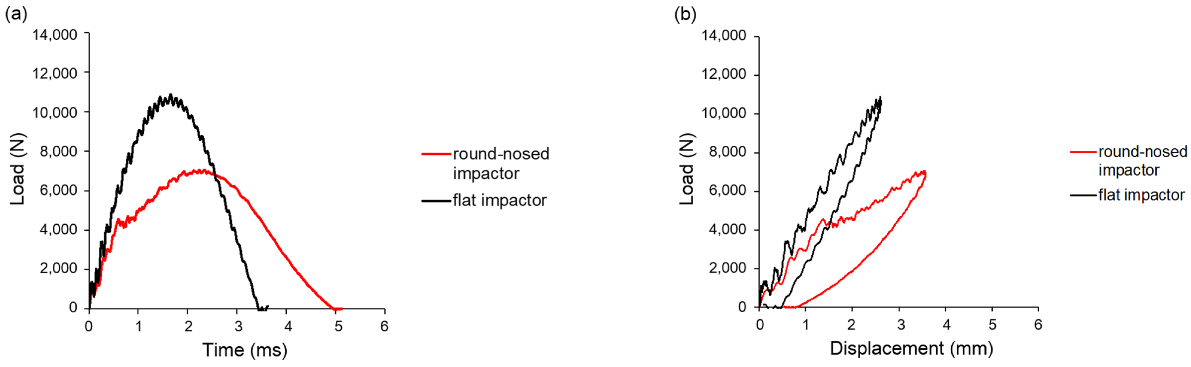
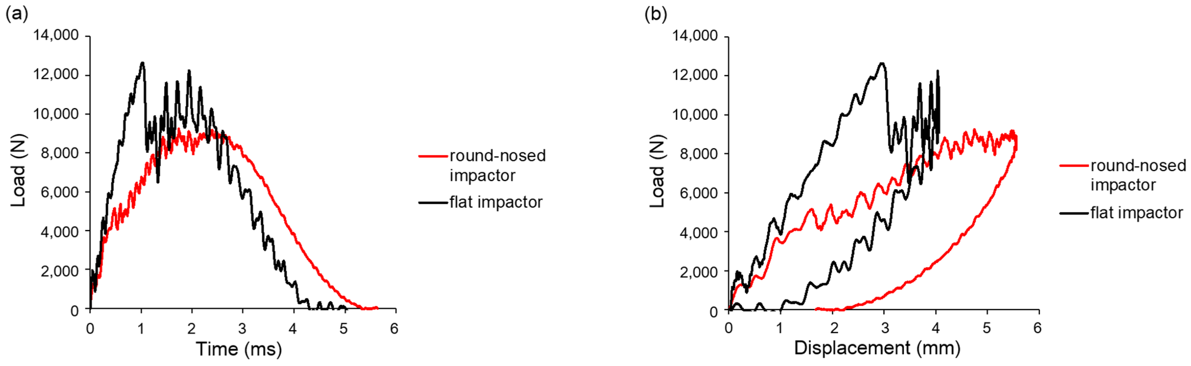
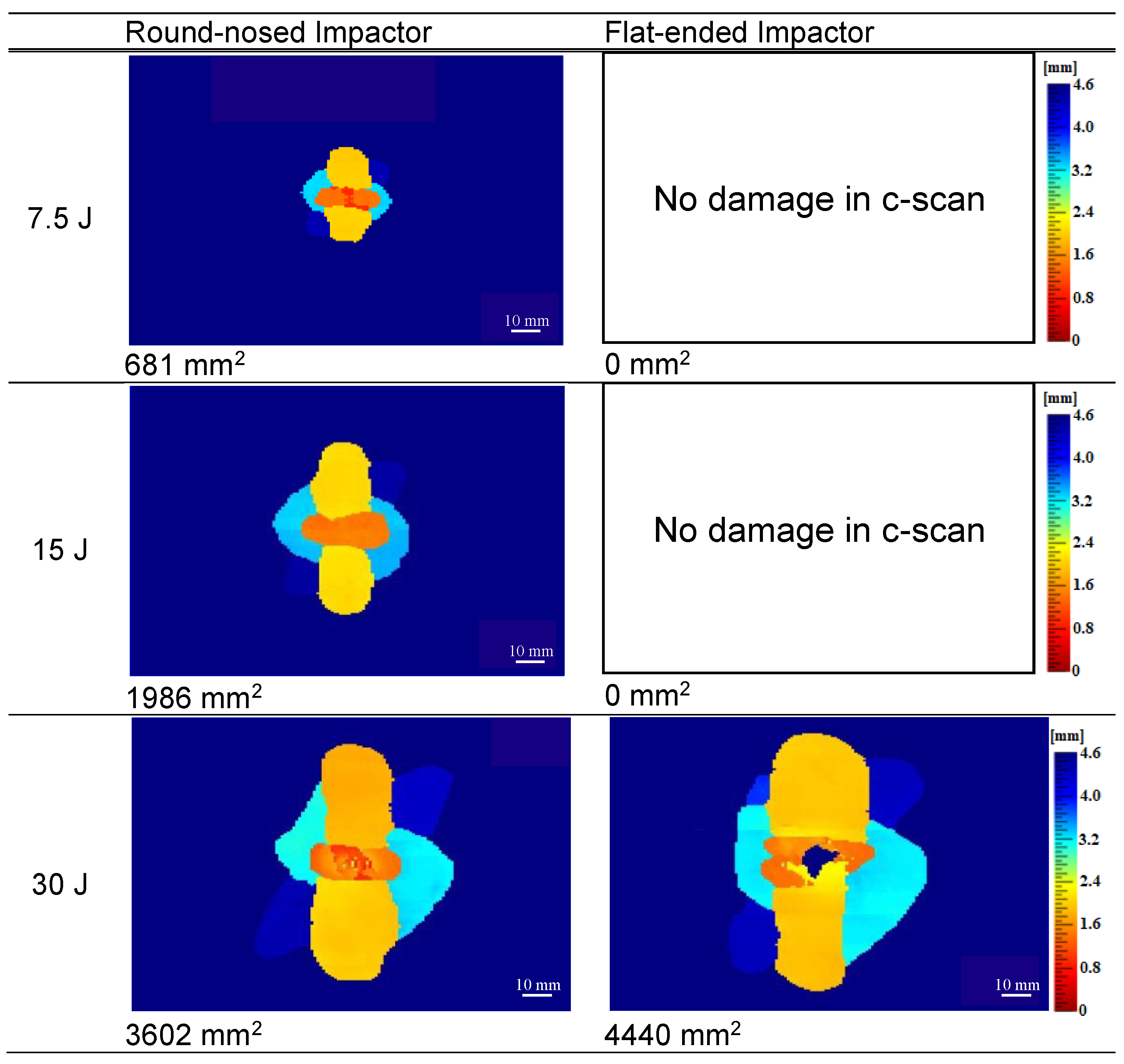
  • Round-nosed impactors induced damage at significantly lower energy thresholds due to localized stress concentration and early indentation, while flat-ended impactors, although requiring higher energies to initiate damage, resulted in larger damage areas and reduced overall panel deflection.
  • The greater out-of-plane deformation allowed by round-nosed impactors enhanced energy absorption and led to smaller damage zones compared to blunter impacts.
  • The addition of rubber to the flat-ended impactor reduced both peak and damage onset loads while increasing maximum displacement and marginally decreasing the damage area. This behavior is attributed to the viscoelastic properties of the rubber, which allow it to absorb part of the kinetic energy during impact.
  • These findings support the application of soft interfaces—such as rubberized contact surfaces—in aerospace ground equipment, where controlled compliance can mitigate composite damage during accidental impacts.
  • Importantly, the experimental dataset (e.g., differences in initiation loads, delamination areas, and time delays) generated in this work provides a robust reference for the validation of future finite element models and simulation-based analyses of impact events in composite laminates. It enables predictive modeling of damage initiation and propagation under different impactor shapes and contact conditions.

Author Contributions

Conceptualization, H.L. and J.P.D. (John P. Dear); Methodology, Z.E.C.H. and H.L.; Validation, Z.E.C.H., Y.Y. and J.P.D. (James P. Dear); Formal analysis, Z.E.C.H. and Y.Y.; Investigation, Z.E.C.H., Y.Y., J.L. and Y.D.; Resources, J.P.D. (John P. Dear); Data curation, Z.E.C.H., Y.Y. and R.A.B.; Writing—original draft preparation, Z.E.C.H. and Y.Y.; Writing—review and editing, J.P.D. (James P. Dear), J.L., R.A.B., Y.D., H.L. and J.P.D. (John P. Dear); Visualization, J.P.D. (James P. Dear), J.L., R.A.B. and Y.D.; Supervision, H.L. and J.P.D. (John P. Dear). All authors have read and agreed to the published version of the manuscript.

Funding

This research received no external funding.

Data Availability Statement

Data will be available based on request.

Acknowledgments

The manufacture of composite samples by Lee Harper and Adam Joesbury in the Composites Research Group at the University of Nottingham is very much appreciated.

Conflicts of Interest

The authors declare no conflict of interest.

References

  1. Griffiths, B. Boeing Sets Pace for Composites Usage in Large Civil Aircraft. 2005. Available online: https://www.compositesworld.com/articles/boeing-sets-pace-for-composite-usage-in-large-civil-aircraft (accessed on 18 January 2022).
  2. Zachariah, S.A.; Pai, K.D.; Shenoy, B.S. Multi-level hybridization in mitigating impact damages in advanced composites—A review on recent trends. Mater. Today Proc. 2021, 46, 9059–9066. [Google Scholar] [CrossRef]
  3. Raut, N.P.; Kolekar, A.B.; Gombi, S.L. Methods of damage detection on composites under low velocity impact. Mater. Today Proc. 2020, 27, 2823–2827. [Google Scholar] [CrossRef]
  4. Kurşun, A.; Şenel, M.; Enginsoy, H.M.; Bayraktar, E. Effect of impactor shapes on the low velocity impact damage of sandwich composite plate: Experimental study and modelling. Compos. Part B Eng. 2016, 86, 143–151. [Google Scholar] [CrossRef]
  5. Yao, L.; Wang, C.; He, W.; Lu, S.; Xie, D. Influence of impactor shape on low-velocity impact behavior of fiber metal laminates combined numerical and experimental approaches. Thin-Walled Struct. 2019, 145, 106399. [Google Scholar] [CrossRef]
  6. Mahesh, V.; Joladarashi, S.; Kulkarni, S.M. Influence of laminate thickness and impactor shape on low velocity impact response of jute-epoxy composite: FE study. Mater. Today Proc. 2020, 28, 545–550. [Google Scholar] [CrossRef]
  7. Mitrevski, T.; Marshall, I.H.; Thomson, R.S.; Jones, R. Low-velocity impacts on preloaded GFRP specimens with various impactor shapes. Compos. Struct. 2006, 76, 209–217. [Google Scholar] [CrossRef]
  8. Yankelevsky, D. Local response of concrete slabs to low velocity missile impact. Int. J. Impact Eng. 1997, 19, 331–343. [Google Scholar] [CrossRef]
  9. Koechlin, P.; Potapov, S. Classification of soft and hard impacts—Applications to aircraft crash. Nucl. Eng. Des. 2009, 239, 613–618. [Google Scholar] [CrossRef]
  10. Clark, G.; Van Blaricum, T.J. Load spectrum modification effects on fatigue of impact-damaged carbon fibre composite coupons. Composites 1987, 18, 243–251. [Google Scholar] [CrossRef]
  11. Batra, R.C.; Gopinath, G.; Zheng, J.Q. Damage and failure in low energy impact of fiber-reinforced polymeric composite laminates. Compos. Struct. 2012, 94, 540–547. [Google Scholar] [CrossRef]
  12. Sjogren, A.; Krasnikovs, A.; Varna, J. Experimental determination of elastic properties of impact damage in carbon fibre/epoxy laminates. Compos. Part A 2001, 32, 1237–1242. [Google Scholar] [CrossRef]
  13. Heimbs, S.; Heller, S.; Middendorf, P.; Hahnel, F.; Weisse, J. Low velocity impact on CFRP plates with compressive preload: Test and modelling. Int. J. Impact Eng. 2009, 36, 1182–1193. [Google Scholar] [CrossRef]
  14. Hongkarnjanakul, N.; Bouvet, C.; Rivallant, S. Validation of low velocity impact modelling on different stacking sequences of CFRP laminates and influence of fibre failure. Compos. Struct. 2013, 106, 549–559. [Google Scholar] [CrossRef]
  15. Zhou, J.; Liao, B.; Shi, Y.; Zuo, Y.; Tuo, H.; Jia, L. Low-velocity impact behaviour and residual tensile strength of CFRP laminates. Compos. Part B Eng. 2019, 161, 300–313. [Google Scholar] [CrossRef]
  16. Caprino, G.; Lopresto, V. On the penetration energy for fibre-reinforced plastics under low-velocity impact conditions. Compos. Sci. Technol. 2001, 61, 65–73. [Google Scholar] [CrossRef]
  17. Cantwell, W.J.; Morton, J. Impact perforation of carbon fibre reinforced plastic. Compos. Sci. Technol. 1990, 38, 119–141. [Google Scholar] [CrossRef]
  18. Li, Z.; Wang, Y.; Xiong, J. Low-velocity impact performance and damage mechanisms of all-CFRP honeycomb sandwich shell. Int. J. Impact Eng. 2025, 199, 105231. [Google Scholar] [CrossRef]
  19. Jing, K.; Zhou, H.; Wang, H.; Yan, H.; Xie, S. Multiscale damage and low-velocity impact study of three-dimensional woven composites. Thin-Walled Struct. 2024, 202, 112132. [Google Scholar] [CrossRef]
  20. Jackson, W.C.; Poe, C.C., Jr. The use of impact force as a scale parameter for the impact response of composite laminates. Compos. Technol. Res. 1993, 15, 282–289. [Google Scholar] [CrossRef]
  21. Ambur, D.; Kemmerly, H. Influence of impactor mass on the damage characteristics and failure strength of laminated composite plates. In Proceedings of the 39th AIAA/ASME/ASCE/AHS/ASC Structures, Structural Dynamics, and Materials Conference and Exhibit, Long Beach, CA, USA, 20–23 April 1998; p. 1784. [Google Scholar] [CrossRef]
  22. Hakim, M.L.; Nafianto, R.; Nugraha, A.D.; Wiranata, A.; Supriyanto, E.; Nugroho, G.; Muflikhun, M.A. Advanced FEA simulation of GFRP and CFRP responses to low velocity impact: Exploring impactor diameter variations and damage mechanisms. Compos. Part C Open Access 2024, 15, 100541. [Google Scholar] [CrossRef]
  23. Qiu, J. Research and analysis on low-velocity impact of composite materials. Sci. Eng. Compos. Mater. 2023, 30, 20220209. [Google Scholar] [CrossRef]
  24. Artero-Guerrero, J.A.; Pernas-Sánchez, J.; López-Puente, J.; Varas, D. Experimental study of the impactor mass effect on the low velocity impact of carbon/epoxy woven laminates. Compos. Struct. 2015, 133, 774–781. [Google Scholar] [CrossRef]
  25. Dau, F.; Dano, M.-L.; Duplessis-Kergomard, Y. Experimental investigations and variability considerations on 3D interlock textile composites used in low velocity soft impact loading. Compos. Struct. 2016, 153, 369–379. [Google Scholar] [CrossRef]
  26. Liu, J.; Liu, H.; Kaboglu, C.; Kong, X.; Ding, Y.; Chai, H.; Blackman, B.R.K.; Kinloch, A.J.; Dear, J.P. The impact performance of woven-fabric thermoplastic and thermoset composites subjected to high-velocity soft- and hard-impact loading. Appl. Compos. Mater. 2019, 26, 1389–1410. [Google Scholar] [CrossRef]
  27. Mitrevski, T.; Marshall, I.H.; Thomsom, R.; Jones, R.; Whittingham, B. The effect of impactor shape on the impact response of composite laminates. Compos. Struct. 2005, 67, 139–148. [Google Scholar] [CrossRef]
  28. Kazemianfar, B.; Esmaeeli, M.; Nami, M.R. Response of 3D woven composites under low velocity impact with different impactor geometries. Aerosp. Sci. Technol. 2020, 102, 105849. [Google Scholar] [CrossRef]
  29. Lv, T.; Yuan, B.; Liu, Y.; Wang, D. Comparative Analysis of Damage and Energy Absorption Mechanisms in Various Plain-weave Fiber Reinforced Composites under Multi-Angle Low-Velocity Impact. Thin-Walled Struct. 2025, 210, 113040. [Google Scholar] [CrossRef]
  30. Reis, P.N.B.; Neto, M.A.; Amaro, A.M. Multi-impact behaviour of composite laminates under constant and different energy levels. Compos. Struct. 2022, 294, 115788. [Google Scholar] [CrossRef]
  31. ASTM D7136/D7136M; Standard Test Method for Measuring the Damage Resistance of a Fiber-Reinforced Polymer Matrix Composite to a Drop-Weight Impact Event. American Society for Testing and Materials: Conshohocken, PA, USA, 2005. [CrossRef]
  32. Liu, H.; Liu, J.; Ding, Y.; Hall, Z.E.; Kong, X.; Zhou, J.; Blackman, B.R.K.; Kinloch, A.J.; Dear, J.P. A three-dimensional elastic-plastic damage model for predicting the impact behaviour of fibre-reinforced polymer-matrix composites. Compos. Part B Eng. 2020, 201, 108389. [Google Scholar] [CrossRef]
  33. Liu, H.; Liu, J.; Ding, Y.; Zheng, J.; Kong, X.; Zhou, J.; Harper, L.; Blackman, B.R.K.; Kinloch, A.J.; Dear, J.P. The behaviour of thermoplastic and thermoset carbon-fibre composites subjected to low-velocity and high-velocity impact. J. Mater. Sci. 2020, 55, 15751–15768. [Google Scholar] [CrossRef]
  34. Liu, H.; Liu, J.; Ding, Y.; Zhou, J.; Kong, X.; Blackman, B.R.K.; Kinloch, A.J.; Falzon, B.G.; Dear, J.P. Effects of impactor geometry on the low velocity impact behaviour of fibre-reinforced composites: An experimental and theoretical investigation. Appl. Compos. Mater. 2020, 27, 533–553. [Google Scholar] [CrossRef]
  35. Liu, J.; Li, Y.; Huang, M.; Zhang, Y.; Lu, Y.; Yue, Q. Numerical analysis of low-velocity impact damage in fiber metal laminate (FML) by introducing plasticity of fiber composite materials. Compos. Struct. 2025, 357, 118912. [Google Scholar] [CrossRef]
  36. Li, Y.; Yang, Y.; Li, J.; Wang, B.; Liao, Y. Experimental-numerical analysis of failure of adhesively bonded lap joints under transverse impact and different temperatures. Int. J. Impact Eng. 2020, 140, 103541. [Google Scholar] [CrossRef]
  37. Liu, J.; Li, Y.; Huang, M.; Zhang, Y.; Lu, Y.; Dong, L. Prediction of low-velocity impact mechanical response and damage in thermoplastic composites considering elastoplastic behavior. Int. J. Impact Eng. 2024, 194, 105099. [Google Scholar] [CrossRef]
  38. PVC Tube Online Ltd. Neoprene Rubber Sheet. Available online: http://www.pvctubeonline.co.uk/neoprene_rubber_sheet.htm (accessed on 16 November 2021).
  39. Liu, X.; Kong, W.; Song, S.; Wang, A. Impact properties and damage assessment of unidirectional aramid/carbon fiber hybrid reinforced polymer composites. Thin-Walled Struct. 2025, 209, 112898. [Google Scholar] [CrossRef]
  40. Patil, S.; Reddy, D.M. Impact damage assessment in carbon fiber reinforced composite using vibration-based new damage index and ultrasonic C-scanning method. Structures 2020, 28, 638–650. [Google Scholar] [CrossRef]
Figure 1. Plan and side views of the quasi-isotropic CFRP panels.
Jcs 09 00230 g001
Figure 2. Drop-weight tower set-up.
Jcs 09 00230 g002
Figure 3. Portable ultrasonic C-scanner set-up.
Jcs 09 00230 g003
Figure 4. Load response curves for pristine CFRP panels subjected to 7.5 J impact using a round-nosed impactor (red line) and a flat-ended impactor (black line): (a) force-time response; (b) force-displacement response.
Jcs 09 00230 g004
Figure 5. Load response curves for pristine CFRP panels subjected to 15 J impact using a round-nosed impactor (red line) and a flat-ended impactor (black line): (a) force-time response; (b) force-displacement response.
Jcs 09 00230 g005
Figure 6. Load response curves for pristine CFRP panels subjected to 30 J impact using a round-nosed impactor (red line) and a flat-ended impactor (black line): (a) force-time response; (b) force-displacement response.
Jcs 09 00230 g006
Figure 7. Ultrasonic C-scan images captured from the top (impacted) surface of pristine CFRP panels subjected to impacts with round-nosed and flat-ended impactors at various energy levels. The corresponding damage area (in mm2) is indicated below each image (the scale bar on the right represents the through-thickness depth of interlaminar damage, ranging from 0 to 4.6 mm—the full thickness of the laminate).
Jcs 09 00230 g007
Figure 8. Load response curves for pristine CFRP panels impacted at 30 J using a flat-ended impactor without rubber and with rubber discs of 1-, 1.5- and 2 mm thickness adhered to the impact surface: (a) force-time response; (b) force-displacement response.
Jcs 09 00230 g008
Figure 9. Ultrasonic C-scan images of pristine CFRP panels captured from the top (impacted) surface following 30 J impact: (a) the panel subjected to impacts with flat-ended impactors without rubber; (b) the panel subjected to impacts with flat-ended impactors fitted with a 1 mm thick rubber disc; (c) the panel subjected to impacts with flat-ended impactors fitted with a 1.5 mm thick rubber disc; and (d) the panel subjected to impacts with flat-ended impactors fitted with a 2 mm thick rubber disc (the scale bar on the right indicates the depth of interlaminar damage through the panel thickness, from 0 to 4.6 mm, corresponding to the total laminate thickness).
Jcs 09 00230 g009
Table 1. Properties of neoprene rubber provided by PVC Tube Online Ltd., Essex UK [38].
PropertyValueUnitsTest Method
Indentation hardness60 shore A −4 +5DegreesASTM D2240 00
Specific gravity1.5 +/− 0.05g/cm3ASTM D792
Tensile strength (minimum)3MPaASTM D412
Elongation at break (minimum)250%-
Minimum continuous working temperature−20°C-
Maximum continuous working temperature65°C-
Maximum intermittent working temperature70°C-
Compression set 70 °C 22 h35% max%ASTM D395 Method B
Table 2. Summary of measured impact response parameters for pristine CFRP panels subjected to varying impact energies using different impactor configurations.
ImpactorImpact Energy (J)Drop-Weight TracesDamage Area (mm2)Variation in Damage Area
Damage Onset Load (N)Damage Onset Time (ms)Peak Load (N)Max. Displacement (mm)
Round-nosed7.544451.050712.4681-
Flat-ended7.5--76491.9--
Round-nosed1545580.670543.61986-
Flat-ended15--10,8792.6--
Round-nosed3041150.492485.63602-
Flat-ended3012,6411.012,6414.04440-
Flat-ended w/1 mm rubber3011,4061.011,4064.54308±2.1%
3011,5301.011,5304.44490
Flat-ended w/1.5 mm rubber3011,1831.211,3304.64250±5.1%
3010,8221.110,8224.64711
Flat-ended w/2 mm rubber3011,4311.311,4314.64144-
Disclaimer/Publisher’s Note: The statements, opinions and data contained in all publications are solely those of the individual author(s) and contributor(s) and not of MDPI and/or the editor(s). MDPI and/or the editor(s) disclaim responsibility for any injury to people or property resulting from any ideas, methods, instructions or products referred to in the content.

