
Predicting Seismic-Induced Settlement of Pipelines Buried in Sandy Soil Reinforced with Concrete and FRP Micropiles: A Genetic Programming Approach

 ,
,  ,
,  ,
,  and
and 
Abstract
1. Introduction
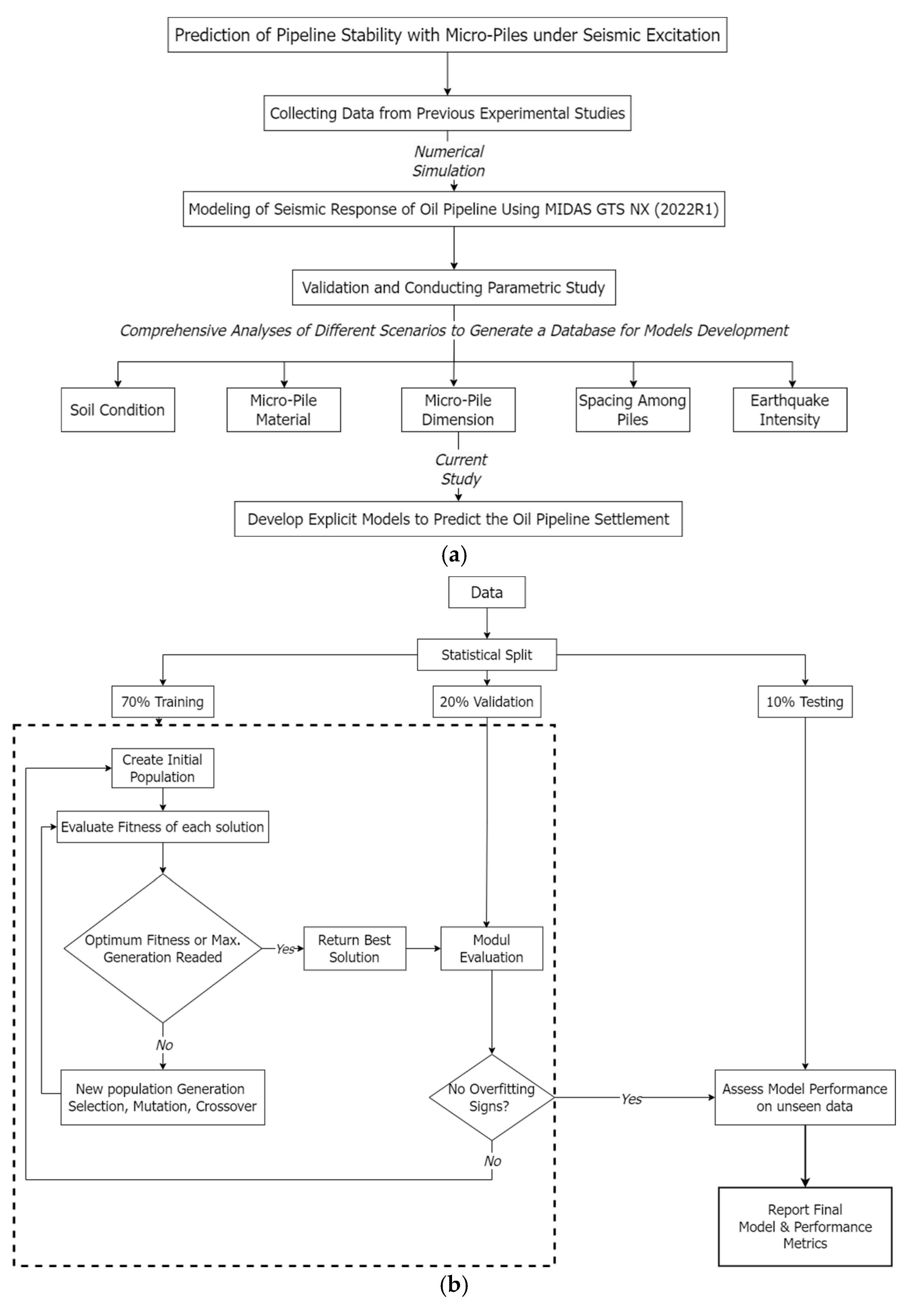
2. Research Methodology and Data Collection
- Use an evolutionary machine learning approach to develop closed-form predictive equations for pipeline settlement with both concrete and polymer micropiles during seismic activity;
- Perform a parametric analysis to evaluate how model parameters influence pipeline settlement, thus providing a deeper understanding of the impact of soil and pile design parameters.
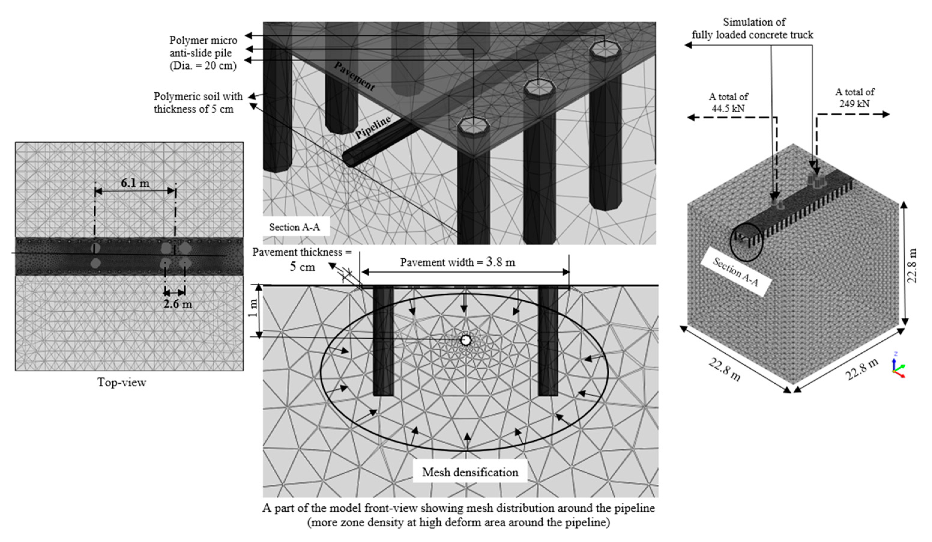
3. Analysis Model for Assessing the Seismic Response of Pipelines
3.1. Finite Element Model for Building the Database
3.2. Genetic Programing
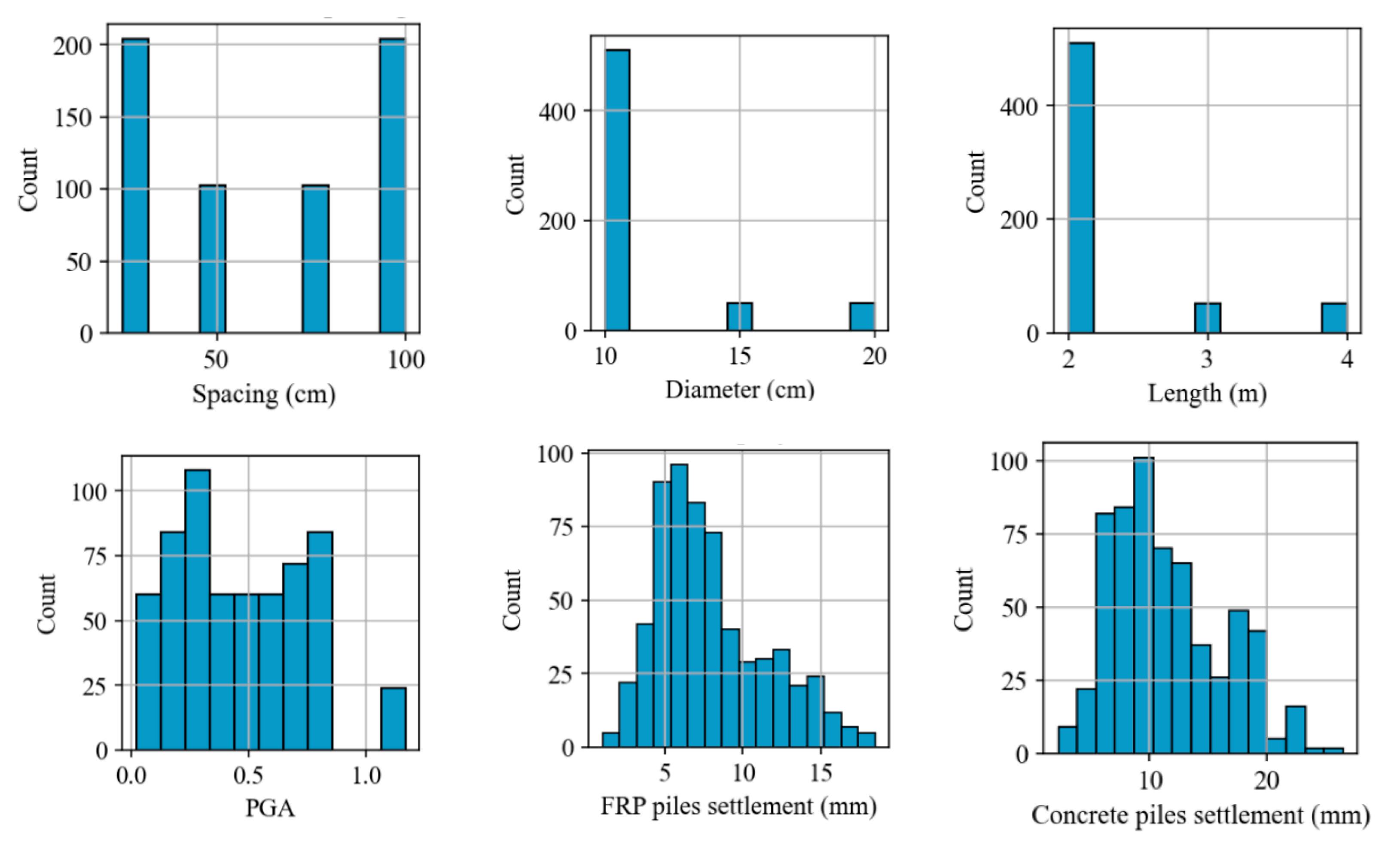
3.3. Data Description
3.4. Data Preprocessing
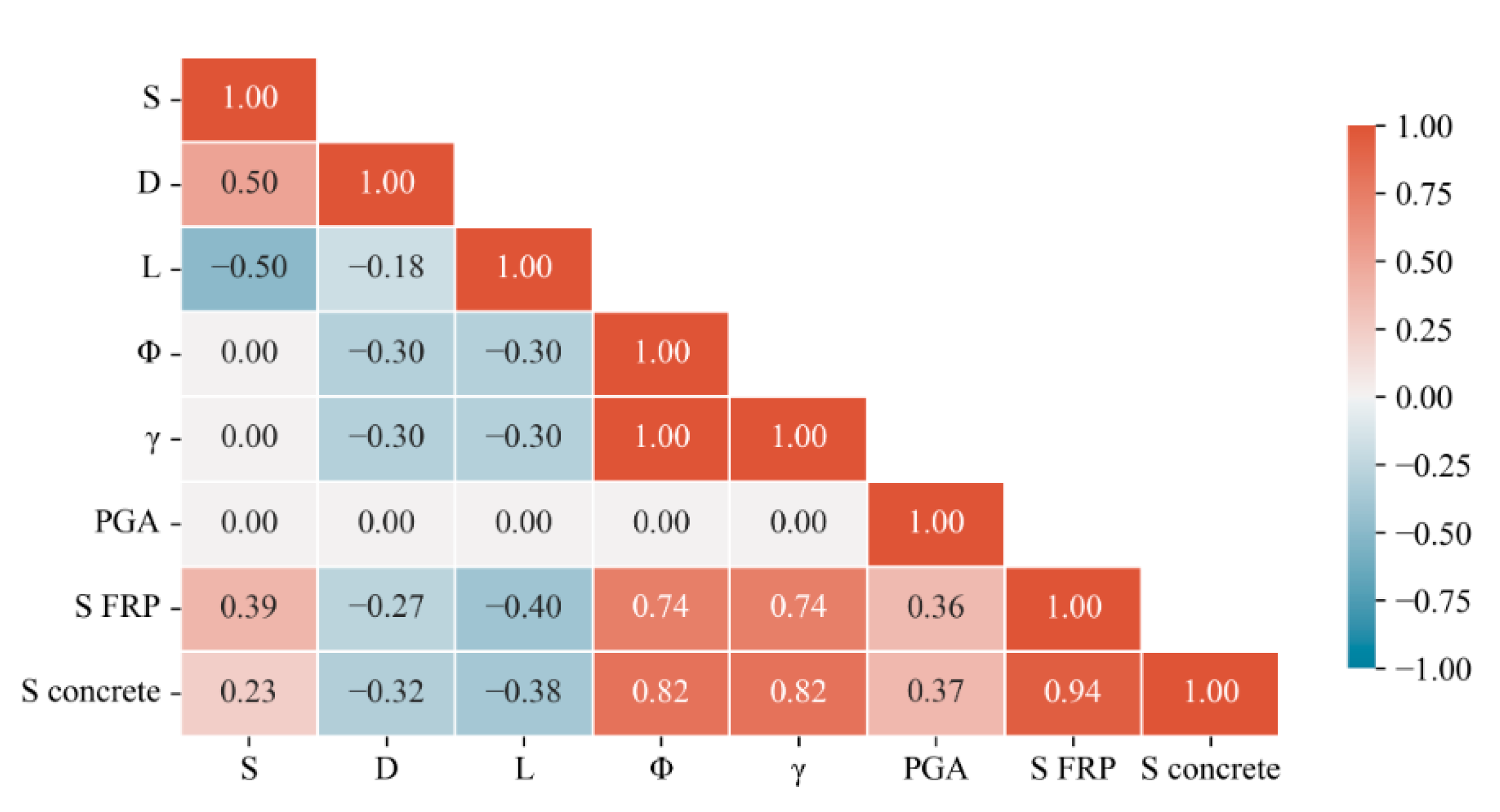
3.4.1. Correlation Analysis
3.4.2. Feature Selection
3.4.3. Data Split
3.5. Model Evaluation
4. Results
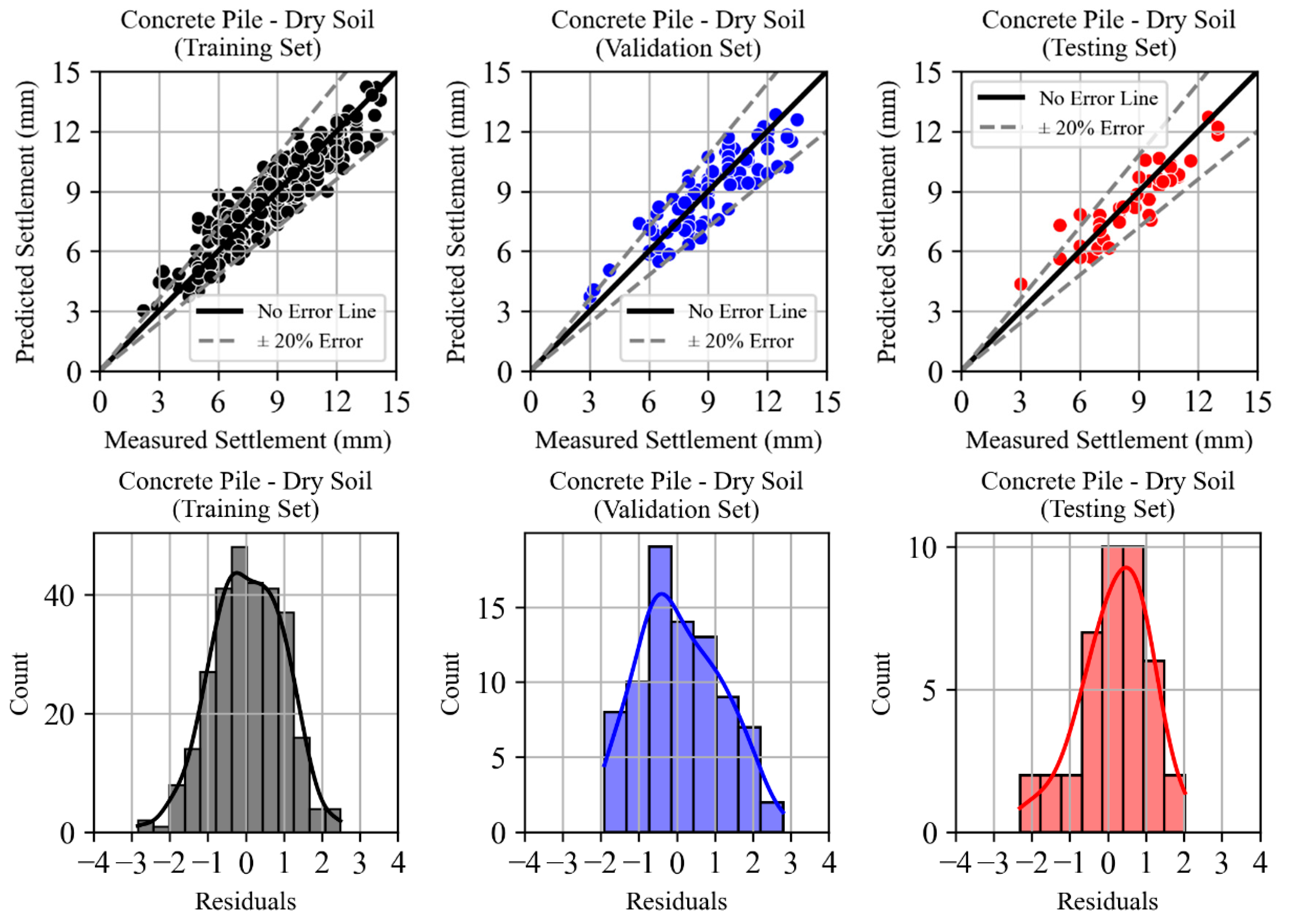
4.1. Dry Soil State
4.1.1. Concrete Micropiles
4.1.2. FRP Micropiles
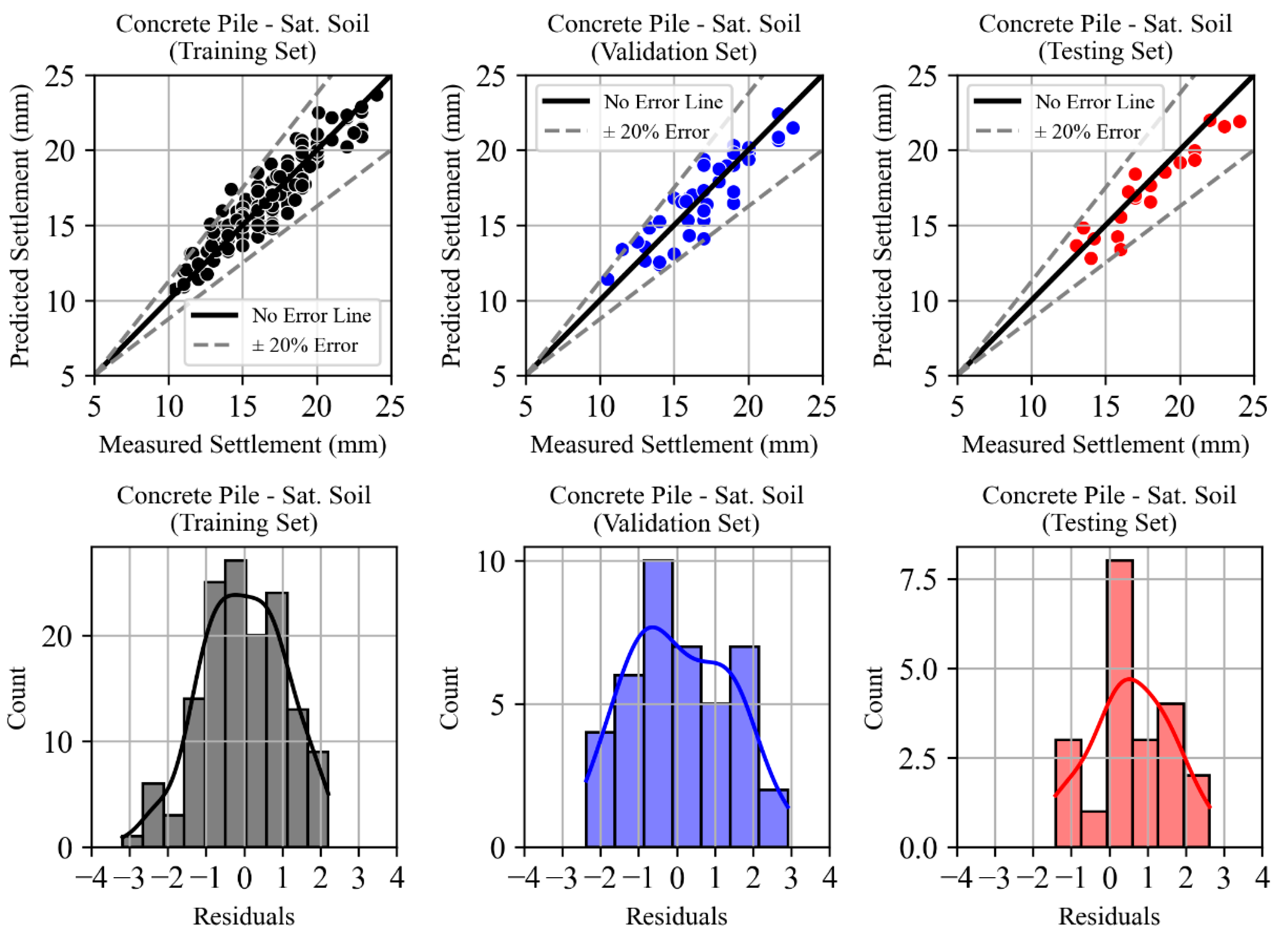
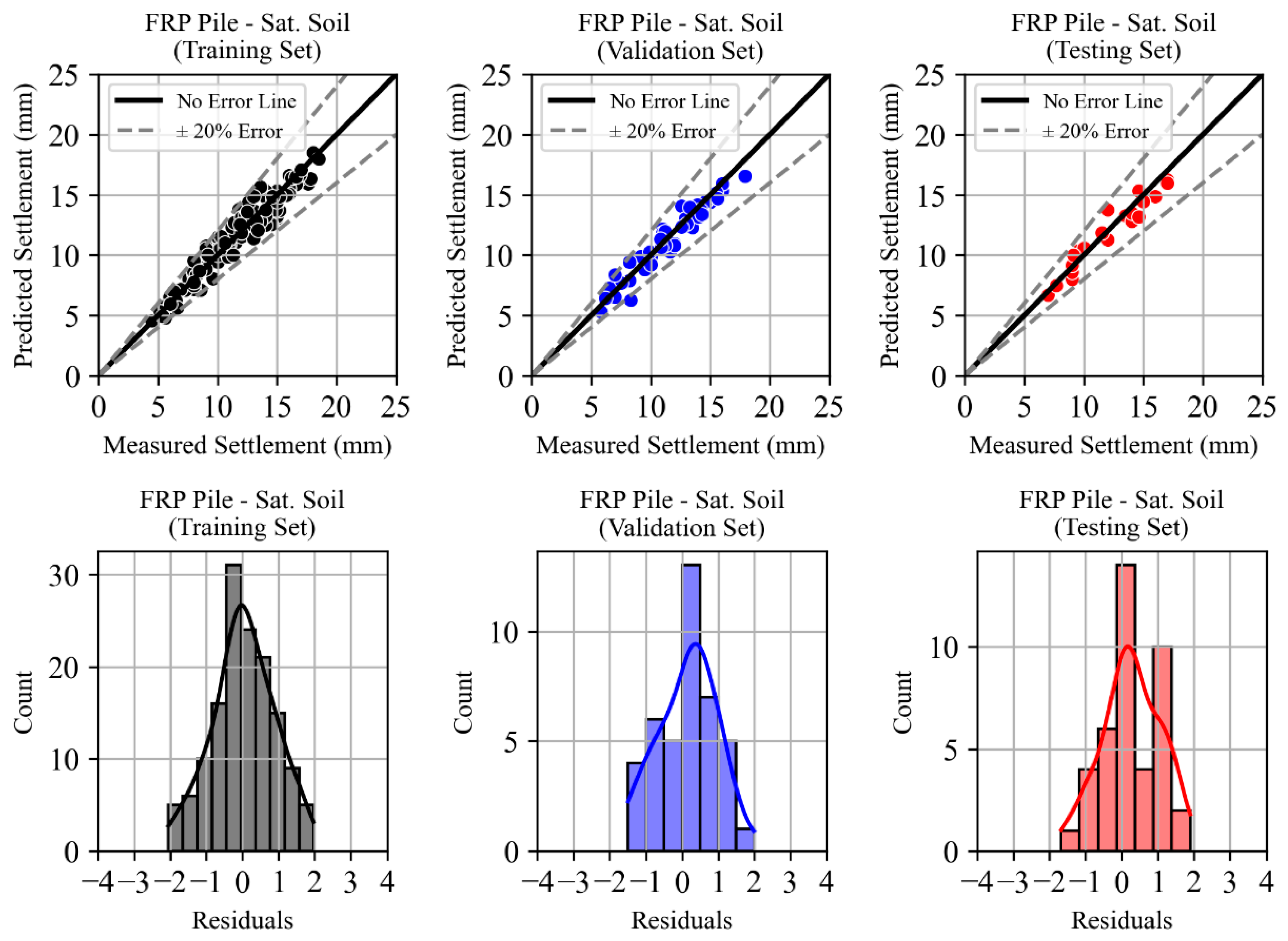
4.2. Saturated Soil State
4.2.1. Concrete Micropiles
4.2.2. FRP Micropiles
5. Discussion and Conclusions
- i.
- FRP micropiles, due to their inherent material properties, are more sensitive to environmental and drying conditions. This variability could introduce higher variability in the dataset (in fact, the dataset for polymer micropiles under drying conditions had a slightly higher proportion of extreme data points), potentially impacting the models’ ability to capture precise settlements under drying conditions;
- ii.
- to enhance the models’ applicability and reduce complexity, some secondary parameters, such as moisture loss rate and polymer-specific drying characteristics, were excluded from the input variables. This simplification may have contributed to a reduced fit in this specific condition.
6. Practical Application and Design Implications
Author Contributions
Funding
Institutional Review Board Statement
Informed Consent Statement
Data Availability Statement
Conflicts of Interest
References
- Adachi, T.; Ellingwood, B.R. Serviceability of Earthquake-Damaged Water Systems: Effects of Electrical Power Availability and Power Backup Systems on System Vulnerability. Reliab. Eng. Syst. Saf. 2008, 93, 78–88. [Google Scholar] [CrossRef]
- Dulger, M.; Kilic, H. Investigation of Earthquake-Induced Pipe Damage in Liquefiable Soils. Appl. Sci. 2024, 14, 4599. [Google Scholar] [CrossRef]
- Yong, Y. Response of pipeline structure subjected to ground motion excitation. Eng. Struct. 1997, 19, 679–684. [Google Scholar] [CrossRef]
- Datta, T.K. Seismic response of buried pipelines: A state-of-the-art review. Nucl. Eng. Des. 1999, 192, 271–284. [Google Scholar] [CrossRef]
- Karinski, Y.S.; Yankelevsky, D.Z. Dynamic analysis of an elastic–plastic multisegment lining buried in soil. Eng. Struct. 2007, 29, 317–328. [Google Scholar] [CrossRef]
- Lee, D.H.; Kim, B.H.; Lee, H.; Kong, J.S. Seismic behavior of a buried gas pipeline under earthquake excitations. Eng. Struct. 2009, 31, 1011–1023. [Google Scholar] [CrossRef]
- Al-Jeznawi, D.; Al-Janabi, M.A.Q.; Shafiqu, Q.S.M.; Jasim, T.N.; Güler, E.; Bernardo, L.F.A.; Andrade, J.M.d.A. Seismic Performance Evaluation of Pipelines Buried in Sandy Soils Reinforced with FRP Micropiles: A Numerical Study. Buildings 2024, 14, 3044. [Google Scholar] [CrossRef]
- Kennedy, R.P.; Chow, A.W.; Williamson, R.A. Fault movement effects on buried oil pipeline. J. Transp. Eng. Div. 1977, 103, 617–633. [Google Scholar] [CrossRef]
- O’Rourke, T.D.; Tratumann, C.H. Buried pipeline response to permanent earthquake ground movements. In Proceedings of the ASME Pressure Vessels and Piping Conference, San Francisco, CA, USA, 12–15 August 1980. [Google Scholar]
- Elyasi, J.; Bastami, M.; Kamalian, M.; Derakhshandi, M. Influence of the topographic effect on the seismic response of buried pipelines. Geoenvironmental Disasters 2021, 8, 22. [Google Scholar] [CrossRef]
- Das, S.; Rahman, M.A.; Farooq, S.M. Response Analysis of Buried Pipeline Under Seismic Action: A Numerical Study. In Proceedings of the International Conference on Planning, Architecture & Civil Engineering (ICPACE 2023), Faculty of Civil Engineering, Rajshahi University of Engineering & Technology (RUET), Rajshahi, Bangladesh, India, 12–14 October 2023. [Google Scholar]
- Sahoo, S.; Naveen, B. Seismic Response of a Buried Pipeline in Sandy Soil Layer: Numerical Approach. In Proceedings of the 10th European Conference on Numerical Methods in Geotechnical Engineering (NUMGE 2023), Imperial College, London, UK, 26–28 June 2023. [Google Scholar]
- Fan, J.; Zhao, X.; Liu, J.; Huang, B. Seismic response of buried pipes in sloping medium dense sand. Soil Dyn. Earthq. Eng. 2023, 170, 107867. [Google Scholar] [CrossRef]
- Darvishi, R.; Jafarian, Y.; Lashgari, A.; Askari, F. Seismic Interactive Deformations of Pipeline Buried in Sandy Slopes Using Numerical Modeling with a Systematic Calibration Procedure. J. Pipeline Syst. Eng. Pract. 2024, 15, 7315–7335. [Google Scholar] [CrossRef]
- Bao, C.; Ma, X.; Lim, K.S.; Chen, G.; Xu, F.; Tan, F.; Abd Hamid, N.H. Seismic Fragility Analysis of Steel Moment-Resisting Frame Structure with Differential Settlement. Soil Dyn. Earthq. Eng. 2021, 141, 106526. [Google Scholar] [CrossRef]
- Mantakas, A.; Tsatsis, A.; Loli, M.; Karabatsos, G.; Gazetas, G. Seismic Response of a Motorway Bridge Founded in an Active Landslide: A Case Study. Bull Earthq. Eng. 2023, 21, 605–632. [Google Scholar] [CrossRef]
- Nettis, A.; Di Mucci, V.M.; Ruggieri, S.; Uva, G. Seismic Fragility and Risk Assessment of Isolated Bridges Subjected to Pre-Existing Ground Displacements. Soil Dyn. Earthq. Eng. 2025, 194, 109335. [Google Scholar] [CrossRef]
- Li, N.; Men, Y.; Gao, O.; Liu, X. Seismic response of landslide with micropiles. IOP Conf. Ser. Mater. Sci. Eng. 2018, 392, 042014. [Google Scholar] [CrossRef]
- Lampo, R.; Nosker, T.; Bamo, D.; Busel, J.; Maher, A. Development and Demonstration of FRP Composite Fender, Loadbearing, and Sheet Piling Systems. In Soils and Foundations; US Army Corps of Engineers Construction Engineering Research Laboratories: Champaign, IL, USA, 1998. [Google Scholar]
- Al-Jeznawi, D.; Jasim, T.N.; Shafiqu, Q.S.M. Evaluating the Use of Polypropylene Polymer in Enhancing the Properties of Swelling Clayey Soil. IOP Conf. Ser. Earth Environ. Sci. 2021, 856, 012015. [Google Scholar] [CrossRef]
- Al-Saray, N.A.; Shafiqu, Q.S.; Ibrahim, M.A. Improvement of Strength Characteristics for Sandy Soils by Polypropylene Fibers (PPF). J. Phys. Conf. Ser. 2021, 1895, 012016. [Google Scholar] [CrossRef]
- Hollaway, L.C. A review of the present and future utilization of FRP composites in the civil infrastructure with reference to their important in-service properties. Constr. Build. Mater. 2010, 24, 2419–2445. [Google Scholar] [CrossRef]
- Zeng, J.-J.; Liao, J.; Ye, Y.-Y.; Guo, Y.-C.; Zheng, Y.; Tan, L.-H. Behavior of FRP Spiral Strip-Confined Concrete under Cyclic Axial Compression. Constr. Build. Mater. 2021, 295, 123544. [Google Scholar] [CrossRef]
- Zeng, J.-J.; Zeng, W.-B.; Ye, Y.-Y.; Liao, J.; Zhuge, Y.; Fan, T.-H. Flexural Behavior of FRP Grid Reinforced Ultra-High-Performance Concrete Composite Plates with Different Types of Fibers. Eng. Struct. 2022, 272, 115020. [Google Scholar] [CrossRef]
- Guades, E.; Aravinthan, T.; Islam, M.; Manalo, A. A review on the driving performance of FRP composite piles. Compos. Struct. 2012, 94, 1932–1942. [Google Scholar] [CrossRef]
- Shaia, H.A. Behavior of Fiber Reinforced Polymer Composite Piles: Experimental and Numerical Study. Ph.D. Thesis, The University of Manchester, Manchester, UK, 2013. [Google Scholar]
- Hosseini, M.A.; Rayhani, M.T. Seismic evaluation of frictional FRP piles in saturated sands using shaking table tests. Soil Dyn. Earthq. Eng. 2022, 163, 107545. [Google Scholar] [CrossRef]
- Barbosa, V.D.; Galgoul, N.S. Designing Piled Foundations with a Full 3D Model. Open Constr. Build. Technol. J. 2018, 12, 65–78. [Google Scholar] [CrossRef]
- Wang, K.; Gaidai, O.; Wang, F.; Xu, X.; Zhang, T.; Deng, H. Artificial Neural Network-Based Prediction of the Extreme Response of Floating Offshore Wind Turbines under Operating Conditions. J. Mar. Sci. Eng. 2023, 11, 1807. [Google Scholar] [CrossRef]
- Wu, Q.; Ding, X.; Zhang, Y. Dynamic interaction of coral sand–pile-superstructure during earthquakes: 3D Numerical simulations. Mar. Georesour. Geotechnol. 2023, 41, 774–790. [Google Scholar] [CrossRef]
- Al-Jeznawi, D.; Jais, I.B.M.; Albusoda, B.S.; Khalid, N. Numerical assessment of pipe pile axial response under seismic excitation. J. Eng. 2023, 29, 10. [Google Scholar] [CrossRef]
- Benemaran, R.S.; Esmaeili-Falak, M. Optimization of cost and mechanical properties of concrete with admixtures using MARS and PSO. Comput. Concr. 2020, 26, 309–316. [Google Scholar]
- Qu, X.-Q.; Wang, R.; Zhang, J.-M.; He, B. Influence of Soil Plug on the Seismic Response of Bucket Foundations in Liquefiable Seabed. J. Mar. Sci. Eng. 2023, 11, 598. [Google Scholar] [CrossRef]
- Merghadi, A.; Yunus, A.P.; Dou, J.; Whiteley, J.; ThaiPham, B.; Bui, D.T.; Avtar, R.; Abderrahmane, B. Machine Learning Methods for Landslide Susceptibility Studies: A Comparative Overview of Algorithm Performance. Earth Sci. Rev. 2020, 207, 103225. [Google Scholar] [CrossRef]
- Jiang, F.; Huo, L.; Chen, D.; Cao, L.; Zhao, R.; Li, Y.; Guo, T. The Controlling Factors and Prediction Model of Pore Structure in Global Shale Sediments Based on Random Forest Machine Learning. Earth Sci. Rev. 2023, 241, 104442. [Google Scholar] [CrossRef]
- Zhang, Y.; Hu, X.; Tannant, D.D.; Zhang, G.; Tan, F. Field monitoring and deformation characteristics of a landslide with piles in the Three Gorges Reservoir area. Landslides 2018, 15, 581–592. [Google Scholar] [CrossRef]
- Hanna, A.M.; Morcous, G.; Helmy, M. Efficiency of pile groups installed in cohesionless soil using artificial neural networks. Can. Geotech. J. 2004, 41, 1241–1249. [Google Scholar] [CrossRef]
- Xu, B.; Deng, J.; Liu, X.; Chang, A.; Chen, J.; Zhang, D. A Review on Optimal Design of Fluid Machinery Using Machine Learning Techniques. J. Mar. Sci. Eng. 2023, 11, 941. [Google Scholar] [CrossRef]
- Rumelhart, D.E.; Hinton, G.E.; Williams, R.J. Learning internal representation by error propagation. In Parallel Distributed Processing; Rumelhart, D.E., McClelland, J.L., Eds.; MIT Press: Cambridge, MA, USA, 1986; Chapter 8; Volume 1. [Google Scholar]
- Anikiev, D.; Birnie, C.; Waheed, U.b.; Alkhalifah, T.; Gu, C.; Verschuur, D.J.; Eisner, L. Machine Learning in Microseismic Monitoring. Earth Sci. Rev. 2023, 239, 104371. [Google Scholar] [CrossRef]
- Goldstein, E.B.; Coco, G.; Plant, N.G. A Review of Machine Learning Applications to Coastal Sediment Transport and Morphodynamics. Earth Sci. Rev. 2019, 194, 97–108. [Google Scholar] [CrossRef]
- Nur, A.S.A.; Rahman, R.; Abdullah, M.S. Development of a machine learning algorithm for fake news detection on Twitter. Indones. J. Electr. Eng. Comput. Sci. 2024, 35, 1732–1743. [Google Scholar]
- Taraghi, P.; Li, Y.; Yoosef-Ghodsi, N.; Fowler, M.; Kainat, M.; Adeeb, S. Response of Buried Pipelines Under Permanent Ground Movements: Physics-Informed Deep Neural Network Approach. In Proceedings of the Pressure Vessels & Piping Conference (ASME 2023), Atlanta, GA, USA, 16–21 July 2023. [Google Scholar]
- Koza, J.R. Genetically breeding populations of computer programs to solve problems in artificial intelligence. In Proceedings of the 2nd International IEEE Conference on Tools for Artificial Intelligence, Herndon, VA, USA, 6–9 November 1990; pp. 819–827. [Google Scholar] [CrossRef]
- Zhao, H.; Wang, Y.; Li, X.; Guo, P.; Lin, H. Prediction of Maximum Tunnel Uplift Caused by Overlying Excavation Using XGBoost Algorithm with Bayesian Optimization. Appl. Sci. 2023, 13, 9726. [Google Scholar] [CrossRef]
- Hu, X.; Shentu, J.; Xie, N.; Huang, Y.; Lei, G.; Hu, H.; Guo, P.; Gong, X. Predicting Triaxial Compressive Strength of High-Temperature Treated Rock Using Machine Learning Techniques. J. Rock Mech. Geotech. Eng. 2023, 15, 2072–2082. [Google Scholar] [CrossRef]
- Huang, Z.-K.; Zhang, D.-M.; Xie, X.-C. A practical ANN model for predicting the excavation-induced tunnel horizontal displacement in soft soils. Undergr. Space 2022, 7, 278–293. [Google Scholar] [CrossRef]
- Mousavi, S.M.; Beroza, G.C. Machine Learning in Earthquake Seismology. Annu. Rev. Earth Planet. Sci. 2023, 51, 105–129. [Google Scholar] [CrossRef]
- Boubou, R.; Emeriault, F.; Kastner, R. Artificial Neural Network Application for the Prediction of Ground Surface Movements Induced by Shield Tunnelling. Can. Geotech. J. 2010, 47, 1214–1233. [Google Scholar] [CrossRef]
- Mahdevari, S.; Torabi, S.R.; Monjezi, M. Application of Artificial Intelligence Algorithms in Predicting Tunnel Convergence to Avoid TBM Jamming Phenomenon. Int. J. Rock Mech. Min. 2012, 55, 33–44. [Google Scholar] [CrossRef]
- Radwan, N.A.A. Improvement of Pipeline Settlement Using Micro Piles. J. Eng. Sci. Part A Civ. Eng. 2022, 50, 89–99. [Google Scholar] [CrossRef]
- Wang, Y.; Han, M.; Yu, X.; Guo, C.; Shao, J. Optimal Design and Numerical Analysis of Soil Slope Reinforcement by a New Developed Polymer Micro Anti-slide Pile. Preprint 2021. [CrossRef]
- Al-Jeznawi, D.; Khatti, J.; Al-Janabi, M.A.Q.; Grover, K.S.; Jais, I.B.M.; Albusoda, B.S.; Khalid, N. Seismic performance assessment of single pipe piles using three-dimensional finite element modeling considering different parameters. Earthq. Struct. 2023, 24, 455–475. [Google Scholar] [CrossRef]
- Al-Jeznawi, D.; Jais, I.B.; Albusoda, B.S.; Alzabeebee4, S.; Al-Janabi, M.A.Q.; Keawsawasvong, S. Response of Pipe Piles Embedded in Sandy Soils Under Seismic Loads. Transp. Infrastruct. Geotechnol. 2024, 11, 1092–1118. [Google Scholar] [CrossRef]
- Sharifi, S.; Abrishami, S.; Gandomi, A.H. Consolidation assessment using multi expression programming. Appl. Soft Comput. 2020, 86, 105842. [Google Scholar] [CrossRef]
- Beaty, M.H.; Byrne, P.M. UBCSAND Constitutive Model Version 904aR: Summary and User Guide. Presented at the Course “Seismic Deformation Analyses of Embankment Dams Considering Liquefaction Effects”, Davis, CA, USA, 22–24 September 2009. Available online: https://bouassidageotechnics.wordpress.com/wp-content/uploads/2016/12/ubcsand_udm_documentation.pdf (accessed on 10 March 2025).
- ASTM D1586-99; Standard Test Method for Penetration Test and Split-Barrel Sampling of Soils. ASTM International: West Conshohocken, PA, USA, 1999.
- Sadik, L. Developing Prediction Equations for Soil Resilient Modulus Using Evolutionary Machine Learning. Transp. Infrastruct. Geotech. 2023, 11, 1598–1620. [Google Scholar] [CrossRef]
- Willis, M.J.; Hiden, H.; Marenbach, P.; McKay, B.; Montague, G. Genetic Programming: An Introduction and Survey of Applications. In Proceedings of the Second International Conference on Genetic Algorithms in Engineering Systems: Innovations and Applications, Glasgow, UK, 2–4 September 1997. [Google Scholar]
- Poli, R.; Langdon, W.B.; McPhee, N.F. A Field Guide to Genetic Programming; Lulu Enterprises Ltd.: London, UK, 2008. [Google Scholar]
- Sun, Z.; Li, Y.; Yang, Y.; Su, L.; Xie, S. Splitting tensile strength of basalt fiber reinforced coral aggregate concrete: Optimized XGBoost models and experimental validation. Constr. Build. Mater. 2024, 416, 135133. [Google Scholar] [CrossRef]
- Sun, Z.; Li, Y.; Su, L.; Niu, D.; Luo, D.; He, W.; Xie, S. Investigation of electrical resistivity for fiber-reinforced coral aggregate concrete. Constr. Build. Mater. 2024, 414, 135011. [Google Scholar] [CrossRef]
- James, G.; Witten, D.; Hastie, T.; Tibshirani, R. An Introduction to Statistical Learning; Springer: New York, NY, USA, 2013. [Google Scholar]
- Sadik, L.; Samui, P. Uncertainty-Aware Prediction of Bearing Capacity of Shallow Foundations Resting on Cohesionless Soils Using Bayesian Regression. Geotech. Geol. Eng. 2024, 42, 3919–3937. [Google Scholar] [CrossRef]
- Tokar; Johnson, P. Rainfall-Runoff Modeling Using Artificial Neural Networks. J. Hydrol. Eng. 1999, 4, 232–239. [Google Scholar] [CrossRef]
- Xu, Y.; Goodacre, R. On Splitting Training and Validation Set: A Comparative Study of Cross-Validation, Bootstrap and Systematic Sampling for Estimating the Generalization Performance of Supervised Learning. J. Anal. Test. 2018, 2, 249–262. [Google Scholar] [CrossRef] [PubMed]
- Tan, J.; Yang, J.; Wu, S.; Chen, G.; Zhao, J. A critical look at the current train/test split in machine learning. arXiv 2021, arXiv:2106.04525. [Google Scholar] [CrossRef]


| 1 | Generate an initial population of random solutions |
| 2 | Repeat |
| 3 | Evaluate the fitness of each solution in the population. |
| 4 | Select one or more solutions for genetic operations, with selection probability determined by fitness. |
| 5 | Apply genetic operations (e.g., crossover and mutation) with predefined probabilities to create new solutions. |
| 6 | Until a satisfactory solution is identified, or a termination criterion is met (e.g., reaching a maximum number of generations) |
| 7 | Return the best-performing solution |
| Attribute | Count | Mean | SD | Min | Max |
|---|---|---|---|---|---|
| S (cm) | 612 | 62.5 | 31.48 | 25 | 100 |
| D (cm) | 612 | 11.25 | 2.97 | 10 | 20 |
| L (m) | 612 | 2.25 | 0.59 | 2 | 4 |
| Ø (°) | 612 | 30.33 | 0.47 | 30 | 31 |
| γ (KN/m3) | 612 | 19 | 1.41 | 18 | 21 |
| PGA (g) | 612 | 0.46 | 0.27 | 0.02 | 1.17 |
| SFRP (mm) | 612 | 7.93 | 3.54 | 1.02 | 18.5 |
| SConcrete (mm) | 612 | 11.50 | 4.72 | 2.2 | 26.5 |
| Training Set | |||||
| Attribute | Count | Mean | SD | Min | Max |
| S (cm) | 285 | 61.84 | 33.00 | 25 | 100 |
| D (cm) | 285 | 11.78 | 3.40 | 10 | 20 |
| L (m) | 285 | 2.37 | 0.70 | 2 | 4 |
| PGA (g) | 285 | 0.46 | 0.27 | 0.02 | 1.17 |
| SFRP (mm) | 285 | 6.06 | 1.93 | 1.4 | 11.2 |
| SConcrete (mm) | 285 | 8.71 | 2.41 | 2.2 | 14.2 |
| Validation set | |||||
| Attribute | count | mean | SD | min | max |
| S (cm) | 82 | 67.37 | 33.72 | 25 | 100 |
| D (cm) | 82 | 12.25 | 3.78 | 10 | 20 |
| L (m) | 82 | 2.378 | 0.69 | 2 | 4 |
| PGA (g) | 82 | 0.47 | 0.25 | 0.02 | 1.17 |
| SFRP (mm) | 82 | 6.26 | 1.74 | 2.8 | 10.5 |
| SConcrete (mm) | 82 | 8.95 | 2.43 | 3 | 13.5 |
| Testing set | |||||
| Attribute | count | mean | SD | min | max |
| S (cm) | 41 | 57.31 | 32.23 | 25 | 100 |
| D (cm) | 41 | 11.70 | 3.46 | 10 | 20 |
| L (m) | 41 | 2.36 | 0.62 | 2 | 4 |
| PGA (g) | 41 | 0.40 | 0.30 | 0.02 | 1.17 |
| SFRP (mm) | 41 | 5.69 | 1.74 | 1.02 | 11.2 |
| SConcrete (mm) | 41 | 8.62 | 2.29 | 3 | 13 |
| Training Set | |||||
| Attribute | Count | Mean | SD | Min | Max |
| S (cm) | 142 | 63.02 | 28.20 | 25 | 100 |
| D (cm) | 142 | 10 | 0 | 10 | 10 |
| L (m) | 142 | 2 | 0 | 2 | 2 |
| PGA (g) | 142 | 0.45 | 0.27 | 0.02 | 1.17 |
| SFRP (mm) | 142 | 11.63 | 3.18 | 4.5 | 18.5 |
| SConcrete (mm) | 142 | 16.93 | 3.21 | 10.4 | 26.5 |
| Validation set | |||||
| Attribute | count | mean | SD | min | max |
| S (cm) | 41 | 61.58 | 26.86 | 25 | 100 |
| D (cm) | 41 | 10 | 0 | 10 | 10 |
| L (m) | 41 | 2 | 0 | 2 | 2 |
| PGA (g) | 41 | 0.44 | 0.25 | 0.04 | 1.17 |
| SFRP (mm) | 41 | 11.57 | 3.07 | 5.8 | 17.9 |
| SConcrete (mm) | 41 | 16.80 | 2.99 | 10.5 | 23 |
| Testing set | |||||
| Attribute | count | mean | SD | min | max |
| S (cm) | 21 | 60.71 | 30.17 | 25 | 100 |
| D (cm) | 21 | 10 | 0 | 10 | 10 |
| L (m) | 21 | 2 | 0 | 2 | 2 |
| PGA (g) | 21 | 0.51 | 0.28 | 0.02 | 1.17 |
| SFRP (mm) | 21 | 11.96 | 3.10 | 7 | 17 |
| SConcrete (mm) | 21 | 17.85 | 3.11 | 13 | 24 |
| Model | Training Set | Validation Set | Testing Set | ||||||
|---|---|---|---|---|---|---|---|---|---|
| R2 | RMSE (mm) | MAE (mm) | R2 | RMSE (mm) | MAE (mm) | R2 | RMSE (mm) | MAE (mm) | |
| 0.84 | 0.93 | 0.76 | 0.80 | 1.09 | 0.90 | 0.83 | 0.93 | 0.74 | |
| 0.85 | 0.72 | 0.57 | 0.80 | 0.77 | 0.61 | 0.76 | 0.83 | 0.66 | |
| 0.88 | 1.10 | 0.89 | 0.80 | 1.31 | 1.12 | 0.85 | 1.18 | 0.95 | |
| 0.92 | 0.86 | 0.68 | 0.92 | 0.81 | 0.68 | 0.92 | 0.83 | 0.73 | |
| Pile Spacing (cm) | Predicted Settlement (mm, FRP) |
|---|---|
| 100 | 11.8 |
| 50 | 7.2 |
| 25 | 5.0 |
Disclaimer/Publisher’s Note: The statements, opinions and data contained in all publications are solely those of the individual author(s) and contributor(s) and not of MDPI and/or the editor(s). MDPI and/or the editor(s) disclaim responsibility for any injury to people or property resulting from any ideas, methods, instructions or products referred to in the content. |
© 2025 by the authors. Licensee MDPI, Basel, Switzerland. This article is an open access article distributed under the terms and conditions of the Creative Commons Attribution (CC BY) license (https://creativecommons.org/licenses/by/4.0/).
Share and Cite
Al-Jeznawi, D.; Al-Janabi, M.A.Q.; Sadik, L.; Bernardo, L.F.A.; Andrade, J.M.d.A. Predicting Seismic-Induced Settlement of Pipelines Buried in Sandy Soil Reinforced with Concrete and FRP Micropiles: A Genetic Programming Approach. J. Compos. Sci. 2025, 9, 207. https://doi.org/10.3390/jcs9050207
Al-Jeznawi D, Al-Janabi MAQ, Sadik L, Bernardo LFA, Andrade JMdA. Predicting Seismic-Induced Settlement of Pipelines Buried in Sandy Soil Reinforced with Concrete and FRP Micropiles: A Genetic Programming Approach. Journal of Composites Science. 2025; 9(5):207. https://doi.org/10.3390/jcs9050207
Chicago/Turabian StyleAl-Jeznawi, Duaa, Musab Aied Qissab Al-Janabi, Laith Sadik, Luís Filipe Almeida Bernardo, and Jorge Miguel de Almeida Andrade. 2025. "Predicting Seismic-Induced Settlement of Pipelines Buried in Sandy Soil Reinforced with Concrete and FRP Micropiles: A Genetic Programming Approach" Journal of Composites Science 9, no. 5: 207. https://doi.org/10.3390/jcs9050207
APA StyleAl-Jeznawi, D., Al-Janabi, M. A. Q., Sadik, L., Bernardo, L. F. A., & Andrade, J. M. d. A. (2025). Predicting Seismic-Induced Settlement of Pipelines Buried in Sandy Soil Reinforced with Concrete and FRP Micropiles: A Genetic Programming Approach. Journal of Composites Science, 9(5), 207. https://doi.org/10.3390/jcs9050207