Abstract
This paper presents research concerning simulating the thermal firebrand effect due to its accumulation in exterior construction wall elements by developing a 3D finite element model (FEM) via ABAQUS (2022) software to analyze the exterior walls commonly applied to the exterior of dwellings in southern Europe and South America. A non-linear thermal transient analysis is undertaken, in which the results are directly compared with a previous experimental campaign, in which firebrands are deposited on localized surfaces of construction wall specimens, and the temperature is measured in the several layers of the construction elements. The walls are composite elements, made of different layer combinations of masonry brick and wood, varying the type of thermal insulation in the internal core from cork to classical rigid rockwool and polystyrene foam (XPS). It can be summarized from the results that the FEM effectively simulates the thermal response of brick, normal wood (NW), and cross-laminated timber (CLT) walls when insulated with materials like cork or rockwool coated with mortar against firebrand accumulation. However, the lack of accounting for uncontrolled combustion leads to inconsistent results. Additionally, for walls using XPS as the insulation material, the model requires further refinement to accurately simulate the melting phenomenon and its thermal impact.
1. Introduction
Wildland fires (WLFs) cause significant material losses and human casualties. Despite ongoing efforts by the scientific community to mitigate their risks, the number of devastating WLFs fires has dramatically increased in recent years [1,2]. This surge is primarily attributed to factors such as climate change, inadequate fuel management practices, and the rapid expansion of human development in WLFs areas. Recent WLFs have caused widespread devastation worldwide.
In Portugal, the 2017 fires led to 117 deaths and 204 injuries [3]. In September 2024, Portugal also battled intense WLFs, particularly in the central and northern regions. The combination of unusually high temperatures and severe drought worsened the situation, making it difficult to control the fires as they spread rapidly. At the time of writing, these fires had already consumed over 135,000 hectares of land and resulted in nine fatalities [4]. Canada experienced its worst WLF season in 2023, with over 17.5 million hectares burned [5]. In the U.S., California and Hawaii were hit by devastating WLFs, including the deadly Maui fire, which claimed at least 97 lives and destroyed 2200 buildings [6]. In South America, Chile faced severe WLFs in February 2023, burning 270,000 hectares and causing 26 deaths, while Bolivia’s wildfires severely affected the Amazon and Pantanal wetlands [7]. Recently, wildfires swept through the Los Angeles region, causing unprecedented destruction. The fires claimed at least 24 lives, forced thousands to evacuate, and destroyed over 12,000 buildings, covering an area of more than 160 km2, larger than the city of San Francisco. Strong Santa Ana winds intensified the blazes, particularly in the Palisades, Eaton, Kenneth, and Hurst regions. Early estimates suggest these could be the costliest wildfires in U.S. history, with projected economic damages ranging from USD 135 billion to USD 150 billion [8].
Firebrands are a major mechanism in the spread of wildfires and play a crucial role in igniting secondary fires [9]. These embers, carried by the wind, can travel distances ranging from 2 km to 9 km ahead of the original fire source [3]. Firebrands remain incandescent for several hours, further increasing their potential to start new fires far from the initial blaze [10]. This phenomenon presents a significant challenge for wildfire management, as studies suggest that at least half of wildfires are ignited by secondary fires, which are often caused by firebrands [11]. In recent decades, there has been research conducted on the topic of firebrand transportation [12,13,14,15,16,17,18]. In this context, studies have focused on utilizing firebrand generators to simulate firebrand ignition in construction elements, aiming to uncover and assess their vulnerabilities to such hazards [19,20,21]. On the other hand, the scientific community has highlighted another mechanism of firebrand ignition, emphasizing the impact of firebrand accumulation on construction elements. Santamaria et al. [22] conducted an experimental study to evaluate the impact of smoldering embers and wood degradation due to thermal exposure. Their findings revealed that flaming ignition occurred when 60 g of embers had accumulated on the wood. The detailed experiments conducted by Suzuki and Manzello [23] are highly relevant, demonstrating that wind speed has a significant influence on the smoldering combustion intensity of accumulated firebrands.
The investigation of Sayaka et al. and Suzuki and Manzello [24] revealed that accumulated firebrands could cause ignitions on fuel beds with high FMC, and the upper limit of FMC for ignition increased from 6 m/s to 8 m/s. Bicelli et al. [25] conducted a numerical study employing a temperature-dependent finite element method to simulate the thermal effects of firebrand accumulation on flat surfaces, using heat flux transmission via convection and radiation. Their findings demonstrated that moisture content up to 20% significantly impacts temperature distribution, underscoring the potential for thermal optimization in designing wildfire-resistant structures. Zhu et al. [26] conducted experimental and numerical studies to examine the glowing combustion behavior and ignition capabilities of firebrand accumulations. The research focused on two firebrand sizes, four coverage densities, and six airspeeds, revealing that airflow is the primary factor influencing the glowing temperatures of firebrands. Analytical modelling demonstrated that the ignition time is primarily governed by the combustion behavior of the firebrands and the heat transfer to the fuel, with significant influence from firebrand size and airflow, and a lesser impact from coverage density. Arruda et al. [27] conducted a detailed experimental study, followed by numerical validation, to evaluate the impact of firebrand accumulations on construction materials. They found that rigid rock wool, aluminum, and cork could withstand firebrand accumulations for extended periods, exceeding 200 min.
The response of construction elements to firebrand accumulation remains insufficiently understood due to the diverse range of materials used and the numerous influencing factors, such as material properties, geometric configurations, and environmental conditions. Experimental studies, while critical for understanding firebrand impacts, are often constrained by their high costs and time-intensive processes. This highlights the need for alternative methods, such as numerical simulations. The primary objective of this study is to simulate a previous experimental campaign that investigated the response of exterior dwelling walls to firebrand accumulation using the finite element model (FEM) via ABAQUS (2022) software. This simulation aims to evaluate the effectiveness of finite element software ABAQUS (2022) in accurately modeling the impact of firebrand accumulation on exterior walls. The predicted results from the simulations are compared against the experimental measurements. Material properties were sourced from the existing literature and design codes to serve as input parameters. The analysis incorporates both geometric and material non-linearities, ensuring a comprehensive evaluation of the behavior of the studied wall specimens under firebrand accumulation.
2. Materials and Methods
This section outlines the methodology used to simulate the thermal effects of firebrand accumulation on exterior composite walls. It clearly details the experimental setup, numerical modeling approach, material properties, boundary conditions, and simulation parameters employed in ABAQUS (2022) software.
2.1. Experimental Campaign Summary
The firebrand accumulation tests outlined in this study were carried out in the laboratory of the CERIS-IST research institute in Portugal. The experimental campaign aimed to evaluate the response of exterior dwelling walls to firebrand accumulation. Three types of wall core layers were studied: bricks, designed according to the Exterior Thermal Insulation Composite Systems (ETICS) methodology, cross-laminated timber (CLT), and normal wood (NW), all utilizing the sandwich methodology, as illustrated in Figure 1. Each wall specimen featured a combination of thermal insulation materials, including composite cork, rigid rockwool, polystyrene foam (XPS), and impermeable membranes, paired with a variety of mortars such as Sika, Weber, and the fire-protective Tria mortar, as detailed in Table 1. Full details of the experimental setup, including a description of the chosen materials and layer geometry, are described in [28].
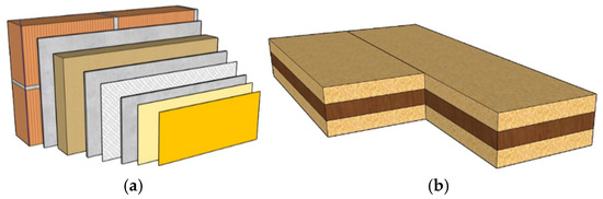
Figure 1.
Composition system details of the composite walls. (a) ETICS; (b) sandwich.

Table 1.
Specifications of the Tested Brick Wall Specimens.
Each wall specimen was constructed in an L-shaped configuration (500 × 600 × 400 mm3), supported by a concrete base slab. Mortar was applied at a fixed thickness of 9 mm, covering both the walls and the connection to the slab to prevent heat flux transmission. The tests followed California Building Code Chapter 7A-4 guidelines [29], exposing each specimen to 1 kg of firebrands at a wind speed of 1.31 ± 0.13 m/s. Thermocouples were embedded in each wall layer, typically one at the base and two per layer on each side, to monitor and record temperature data at a frequency of 1 Hz; the durations of each test ranged from 100 to 200 min, with variations primarily influenced by safety concerns.
2.2. Numerical Simulation
The experimental campaign described in the previous section was simulated using a 3D FEM in ABAQUS (2022) software [30]. The 3D FEM analyses were performed using several key parameters, as detailed below. Surface convection and radiation according the value provided in Eurocode 4 part 1–2 [31] were incorporated into all simulations. All the thermal analyses were performed in Kelvin, with absolute zero as the reference temperature. Since thermal properties vary with temperature, a non-linear transient thermal analysis was conducted using the incremental Newton–Raphson iterative method. To ensure the accuracy of the numerical solution, the maximum allowable temperature change per increment was limited to 10 K, which may necessitate a reduced time step to achieve a more reliable solution for non-linear thermal behavior [32].
2.2.1. Material Properties
In this section, the thermal properties of all materials used in the numerical models, including density, thermal conductivity, and specific heat, are presented. For brick, NW, and CLT, the thermal properties are based on values at ambient temperature from previous studies, with adjustments for elevated temperatures according to Eurocodes 5 and 6, part 1–2 [33,34]. The variation in thermal properties of the mortars was adopted in accordance with a study on the fire behavior of different mortar types [35]. Regarding rockwool, both density and specific heat remain constant at ambient and elevated temperatures. Additionally, temperature-dependent thermal conductivity values were obtained from the literature [36,37,38]. The properties of polystyrene foam (XPS) at elevated temperatures were adopted using ambient temperature values of the previous tests [38], and the temperature variations were derived from Duarte et al. [37]. Finally, for cork, the density value at ambient temperature was adopted from previous work [39], and the reduction ratio at elevated temperatures was taken from the literature [40]. The thermal conductivity and specific heat at ambient temperature, along with the variation in reduction ratios at elevated temperatures, were also adopted from prior studies [39]. The thermal properties for all materials at ambient temperature are presented in Table 2, and the variation ratios with the temperature of each thermal property for all materials are illustrated in Figure 2. The values were used as input in ABAQUS (2022) software according to Equation (1).
where ρ, kc, and cp represent the density, thermal conductivity, and specific heat of the material, respectively. T indicates the given temperature, while 20 refers to the ambient temperature. f denotes the correction ratio for each parameter.
Table 2.
Thermal properties of all studied materials at ambient temperature.
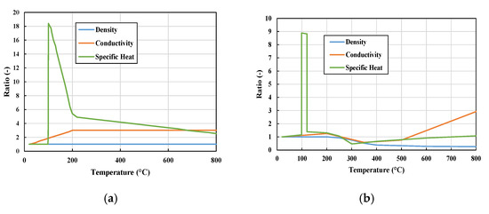
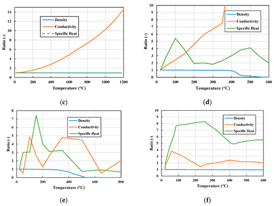
Figure 2.
Variation in thermal property ratios with temperature for (a) brick, (b) NW/CLT, (c) rockwool, (d) XPS, (e) cork, and (f) Weber/Sika/Tria Mortar.
2.2.2. Firebrand Input and Boundary Conditions
Based on the studied conducted by Bearinger et al. [41], which demonstrated that firebrand can transfer heat flux on planar surfaces by convection and radiation, convection and radiation boundary conditions were applied to simulate the heat flux transfer between the firebrands and the wall specimen’s surface. This approach aligns with standard fire safety design practices outlined in structural codes [42] for structures exposed to nominal or performance-based fire scenarios. The firebrand accumulation on the wall specimens was simulated by applying the average temperatures recorded during the tests for each exposed side. These temperatures were used as inputs for convection and radiation within a triangular area on each exposed side of the modeled wall specimens. Additionally, ambient temperature was applied to all outer surfaces except the fire-exposed surface. The film coefficient was set to hf = 35 W/(m2K) for the firebrand-exposed surface and hf = 9 W/(m2K) for the unexposed surface. The Boltzmann constant was σ = 5.67 × 10⁻⁸ W/m2K4, and the emissivity of the fire was ε = 1. Figure 3 provides a detailed illustration of the boundary conditions for the standard wall specimen.
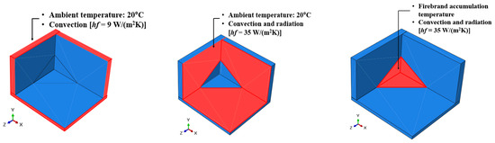
Figure 3.
The applied boundary conditions.
The interaction between the materials was simulated using gap radiation, ε = 1.0, a feature in ABAQUS designed to model radiation between surfaces separated by a narrow gap. However, the interaction between the mortar and other materials was treated as full contact. The view factor, which ranges from 0 to 1, represents the degree of radiative heat transfer, where 0 indicates that there is no radiative heat transfer and 1 indicates that there is no gap. For this simulation, a view factor of 0.99 was used, based on the assumption that the gap between surfaces is less than 1 mm [43].
2.2.3. Chosen Mesh
The mesh employed in this FEMis shown in Figure 4. For all materials, the mesh size was set to 30 mm along the longitudinal direction and 10 mm along the transverse direction (specimen depth). For the mortar layer, a finer mesh size of 5 mm in depth was used to optimize convergence and computational efficiency. The element type used was DC3D8 (8-node linear heat transfer brick) with full integration, which is part of the ABAQUS heat transfer family, to accurately capture the temperature field distribution under a significant flux gradient. Since the maximum allowable nodal temperature change per increment was set to 10 in the ABAQUS/Standard implicit method, ABAQUS automatically controlled the time increments to ensure that no node exceeded this value during any analysis increment [30].
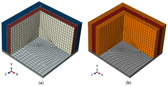
Figure 4.
Standard illustration of the wall specimens modelled for (a) bricks walls (ETICS) and (b) wood walls (sandwich).
3. Results
Thermal analysis was conducted on all studied wall specimens to simulate their response to firebrand accumulation. The obtained results were then compared with the measured data from the tests, focusing on the average temperature recorded across each layer of the wall specimens, as illustrated in Figure 5.
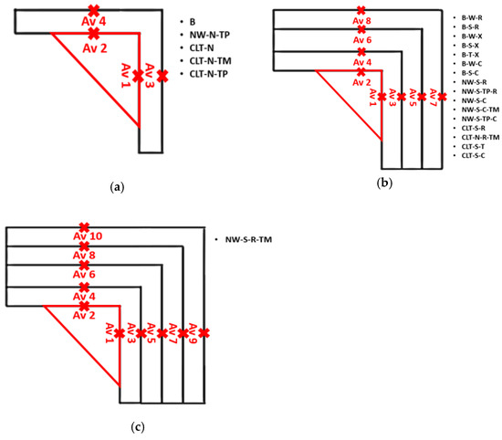
Figure 5.
Illustration of the recording locations for average temperatures across each layer of the studied wall specimens: (a) single layer, (b) three layers, (c) four layers.
3.1. Brick Wall Specimens
The comparison between the numerically predicted and experimentally measured test results for the brick wall specimens is shown in Figure 6. It can be noted that the predicted results for the B, B-W-R, B-S-R, B-T-X, B-W-X, and B-S-C specimens demonstrate close agreement with the measured test results. However, for the B-W-X and B-S-X specimens, which incorporate XPS as the thermal insulation material, a more significant inconsistency is observed. This is attributed to the melting of XPS and destruction of the thermocouple, leading to the uncertainty of the test results.
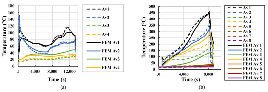
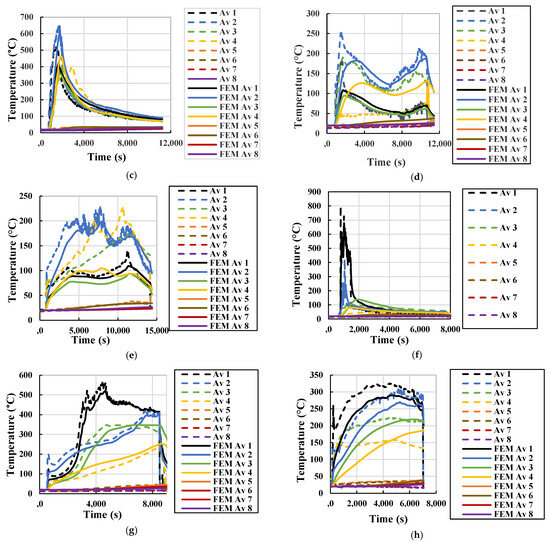
Figure 6.
Comparison between predicted results and measured test results for different brick wall specimens: (a) B, (b) B-W-R, (c) B-S-R, (d) B-W-X, (e) B-S-X, (f) B-T-X, (g) B-W-C, and (h) B-S-C.
3.2. NW Wall Specimens
Figure 7 presents a comparison between the numerically predicted and experimentally measured test results for the NW wall specimens. It can be observed from Figure 7 that the predicted results for the NW-S-NW-S-R-TM, NW-S-R, NW-S-C, and NW-S-C-TM specimens closely align with the measured test results. In contrast, for the NW-N-TP, NW-S-TP-R, and NW-S-TP-C specimens, which utilize Tria Paint as a protective coating, a significant inconsistency is observed between the predicted and measured results. This inconsistency arises because the model does not account for Tria Paint. Based on the interpretation of the results, it can be concluded that Tria Paint not only mitigates the combustion of materials but also decreases heat transfer, despite its small thickness. Therefore, its influence cannot be overlooked in finite element simulations.
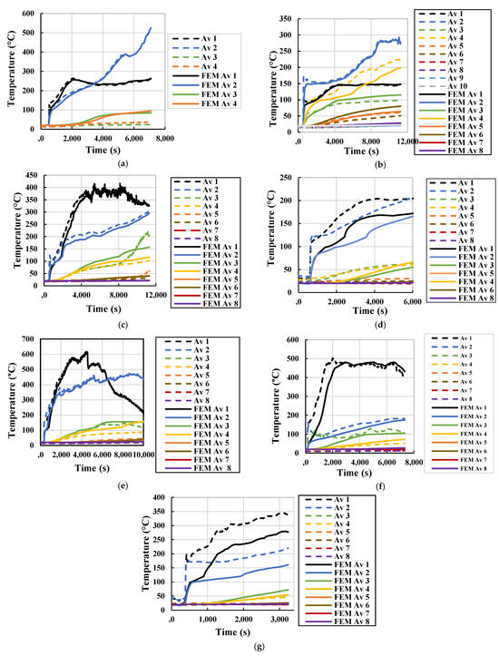
Figure 7.
Comparison between predicted results and measured test results for different NW wall specimens: (a) NW-N-TP, (b) NW-S-R-TM, (c) NW-S-R, (d) NW-S-TP-R, (e) NW-S-C, (f) NW-S-C-TM and (g) NW-S-TP-C.
3.3. CLT Wall Specimens
The comparison of the predicted and measured test results for the CLT wall specimens is displayed in Figure 8. From this figure, for the wall specimens containing Tria Paint as a protective coating, a similar observation to that of the NW walls is noted, which is an inconsistency between the predicted and measured test results. Furthermore, the CLT-S-R specimen exhibits a notable discrepancy with the measured test results due to uncontrolled combustion of CLT, which caused a significant temperature rise in the deeper layers during the firebrand accumulation test. This phenomenon was not accounted for in the FEM. In contrast, for the CLT-N-TM, CLT-N-R-TM, and CLT-S-C specimens, the predicted results align well with the measured test results.
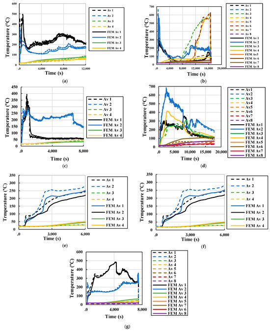
Figure 8.
Comparison between predicted results and measured test results for different CLT wall specimens: (a) CLT-N, (b) CLT-S-R, (c) CLT-N-TM, (d) CLT-N-R-TM, (e) CLT-N-TP, (f) CLT-S-TP-R and (g) CLT-S-C.
4. Discussion
The results indicate that the FEM effectively simulates the thermal response of most wall specimens. However, certain discrepancies highlight the limitations of the numerical approach and the need for further refinements.
The inconsistencies observed in XPS-insulated brick walls are due to the degradation and melting of XPS at lower temperatures. This phenomenon aligns with previous studies. Prior research by Wessies et al. [44] and Arruda et al. [17] highlights the severe impact of firebrand accumulation on XPS, which undergoes rapid thermal breakdown in a short duration and at relatively low temperatures. Therefore, future numerical models should incorporate phase-change properties to better reflect experimental observations.
For NW and CLT walls, the impact of Tria Paint as a protective coating was not considered in the numerical model, leading to an underestimation of its fire resistance. Studies by Suzuki et al. [24] demonstrated that protective coatings can significantly reduce heat transfer and delay combustion. Uncontrolled combustion in CLT-S-R specimens is another factor affecting model accuracy. Prior work by Zhu et al. [26] suggests that smoldering combustion in timber structures can alter heat transfer patterns significantly. Implementing combustion kinetics into numerical simulations may improve the model’s ability to capture such effects.
4.1. Limitations of the Study
The simulated firebrand accumulation may be more severe than traditional firebrand deposition utilizing an ember generator, but it complies with California Building Code Chapter 7A-4 requirements [29]. Additional wall features like windows, doors, and air vents are not considered, which could alter the overall results.
This work numerically studied a concave exterior wall, which may experience more severe effects than a classical plane wall surface when in contact with firebrand accumulation.
4.2. Future Developments
It is anticipated that new double-brick wall geometries will be numerically tested and showcased to the scientific community. Additionally, tests for firebrand buildup will be conducted on innovative materials for the primary layer, such as cellular concrete and concrete blocks. A comparable numerical fire test operation is also planned for traditional ceramic roofs with various thicknesses of insulation.
5. Conclusions
The purpose of this study was to simulate the response of exterior dwelling walls to firebrand accumulation using the finite element software ABAQUS (2022). Numerical simulation results were compared to data from previous experimental campaigns to evaluate finite element modeling’s accuracy and reliability in simulating the thermal reaction of various wall specimens during firebrand accumulation. This study led to the following conclusions:
- The finite element simulations successfully modeled the thermal response of most brick wall specimens, with predicted results showing good agreement with the experimental data. However, discrepancies were observed for wall specimens incorporating XPS insulation, as the numerical model did not account for the melting of XPS during the tests.
- For normal wood wall specimens, the simulations captured the impact of firebrand accumulation with reasonable accuracy. Nonetheless, wall specimens treated with Tria Paint exhibited discrepancies due to the exclusion of the protective coating’s effects in the model.
- Similarly, the finite element simulations effectively reproduced the thermal response of most CLT wall specimens. However, the specimen with rockwool and sandwich settings displayed a marked deviation from experimental results, attributed to uncontrolled combustion during firebrand accumulation tests.
It can be summarized from the results of this study that the finite element model can simulate the response of construction brick, normal wood, and CLT walls with a combination of the following insulators, cork or rockwool coated with mortar, against the accumulation of firebrand.
Author Contributions
Conceptualization, M.R.T.A. and F.B.; methodology, M.R.T.A. and F.B.; software, M.Z. and A.R.A.B.; validation, M.Z. and A.R.A.B.; formal analysis, M.Z., M.R.T.A. and F.B.; investigation, M.Z., M.R.T.A. and F.B.; resources, M.Z.; data curation, M.Z. and M.R.T.A.; writing—original draft preparation, M.Z.; writing—review and editing, M.R.T.A. and F.B.; visualization, M.Z. and M.R.T.A.; supervision, M.R.T.A. and F.B.; project administration, M.R.T.A. and F.B.; funding acquisition, M.R.T.A. and F.B. All authors have read and agreed to the published version of the manuscript.
Funding
The authors would like to acknowledge the Foundation for Science and Technology (FCT), Portugal, for the Project “New Fireproof Dwellings for Wildfire PTDC/ECI-CON/2240/2020” (DOI: 10.54499/PTDC/ECI-CON/2240/2020). The authors are also grateful for the Foundation for Science and Technology’s support through funding UIDB/04625/2020 from the research unit CERIS (DOI: 10.54499/UIDB/04625/2020). The authors would also like to acknowledge FCT for the financing of the doctoral grant SFRH/BD/03935/2023 (DOI: 10.54499/2023.03935.BD).
Data Availability Statement
The raw data supporting the conclusions of this article will be made available by the authors on request.
Acknowledgments
The authors would like to acknowledge FCT, the national funding agency for science, research, and technology, Portugal and CERIS for the financial support. This work was supported by “New Fireproof Dwellings for Wildfire PTDC/ECI-CON/2240/2020” (DOI: 10.54499/PTDC/ECI-CON/2240/2020).
Conflicts of Interest
The authors declare no conflicts of interest.
References
- Jones, M.W.; Kelley, D.I.; Burton, C.A.; Di Giuseppe, F.; Barbosa, M.L.F.; Brambleby, E.; Hartley, A.J.; Lombardi, A.; Mataveli, G.; McNorton, J.R.; et al. State of Wildfires 2023–2024. Earth Syst. Sci. Data 2024, 16, 3601–3685. [Google Scholar]
- Penney, G.; Baker, G.; Valencia, A.; Gorham, D.J.F. A fire safety engineering approach to improving community resilience to the impacts of wildfire. Fire Mater. 2024. [Google Scholar] [CrossRef]
- Guerreiro, J.; Fonseca, C.; Salgueiro, A.; Fernandes, P.; Lopez, I.E.; Neufville, R.; Mateus, F.; Castellnou, R.M.; Sande, S.J.; Moura, J.M.; et al. Avaliação dos Incêndios Ocorridos Entre 14 e 16 de Outubro de 2017 em Portugal Continental; Assembleia da República: Lisboa, Portugal, 2018. [Google Scholar]
- IFRC. Portugal: Wildfires—DREF Operation (MDRPT001); International Federation of Red Cross and Red Crescent Societies: Geneva, Switzerland, 2024. [Google Scholar]
- Jain, P.; Barber, Q.E.; Taylor, S.W.; Whitman, E.; Castellanos Acuna, D.; Boulanger, Y.; Chavardès, R.D.; Chen, J.; Englefield, P.; Flannigan, M.; et al. Drivers and Impacts of the Record-Breaking 2023 Wildfire Season in Canada. Nat. Commun. 2024, 15, 6764. [Google Scholar] [CrossRef]
- Holliday, R.; Krishnamurti, L.S.; Jordan, S.E.; Sia, M.A.; Brenner, L.A.; Monteith, L.L. The Health and Social Impacts of the Maui Wildfires: Post-Disaster Care from a Sociocultural Lens. Hawai’i J. Health Soc. Welf. 2024, 83, 85–87. [Google Scholar] [CrossRef]
- NASA Earth Observatory. Fires Scar the Chilean Landscape. NASA Earth Observatory, 2024. Available online: https://earthobservatory.nasa.gov/images/150994/fires-scar-the-chilean-landscape (accessed on 18 March 2025).
- Business Standard. Los Angeles Wildfires: Deaths, Damages, Evacuations. Business Standard, 2025. Available online: https://www.business-standard.com/world-news/los-angeles-wildfires-deaths-damages-evacuations-2025-125011300426_1.html (accessed on 18 March 2025).
- Suzuki, S.; Manzello, S.L. Investigating the effect of structure to structure separation distance on firebrand accumulation. Front. Mech. Eng. 2021, 6, 628510. [Google Scholar]
- Dossi, S.; Węgrzyński, W.; Rein, G.J.F. Exploratory Simulations on the Effectiveness of Sand Protection Strategies Against Firebrand Accumulation in Wildfires. Fire Mater. 2025. [Google Scholar] [CrossRef]
- Mell, W.E.; Manzello, S.L.; Maranghides, A.; Butry, D.; Rehm, R.G. The wildlandurban interface fire problem current approaches and research needs. Int. J. Wildland Fire 2010, 19, 238–251. [Google Scholar] [CrossRef]
- Suzuki, S.; Manzello, S.L. Investigating Coupled Effect of Radiative Heat Flux and Firebrand Showers on Ignition of Fuel Beds. Fire Technol. 2021, 57, 683–697. [Google Scholar] [CrossRef]
- Wang, H.-H. Analysis on Downwind Distribution of Firebrands Sourced from a Wildland Fire. Fire Technol. 2011, 47, 321–340. [Google Scholar] [CrossRef]
- Tarifa, C.S.; Notario, P.P.d.; Moreno, F.G. On the flight paths and lifetimes of burning particles of wood. Symp. (Int.) Combust. 1965, 10, 1021–1037. [Google Scholar] [CrossRef]
- Albini Usda, F.A. Transport of Firebrands by Line Thermals. Combust. Sci. Technol. 1983, 32, 277–288. [Google Scholar] [CrossRef]
- Matvienko, O.V.; Fil’kov, A.I.; Grishin, A.M. Computational Investigation of the Transport of Burning Particles. J. Eng. Phys. Thermophys. 2016, 89, 1315–1324. [Google Scholar] [CrossRef]
- Arruda, M.R.T.; Cantor, P.; Bicelli, A.; Branco, F. Thermal reaction of firebrand accumulation in construction materials. Case Stud. Constr. Mater. 2024, 20, e02985. [Google Scholar] [CrossRef]
- Wadhwani, R.; Sullivan, C.; Wickramasinghe, A.; Kyng, M.; Khan, N.; Moinuddin, K. A review of firebrand studies on generation and transport. Fire Saf. J. 2022, 134, 103674. [Google Scholar] [CrossRef]
- Manzello, S.L.; Shields, J.R.; Hayashi, Y.; Nii, D. Investigating the vulnerabilities of structures to ignition from a firebrand attack. Fire Saf. Sci. 2008, 9, 143–154. [Google Scholar] [CrossRef]
- Manzello, S.L.; Shields, J.R.; Cleary, T.G.; Maranghides, A.; Mell, W.E.; Yang, J.C.; Hayashi, Y.; Nii, D.; Kurita, T. On the development and characterization of a firebrand generator. Fire Saf. J. 2008, 43, 258–268. [Google Scholar] [CrossRef]
- Manzello, S.L.; Suzuki, S. Experimental investigation of wood decking assemblies exposed to firebrand showers. Fire Saf. J. 2017, 92, 122–131. [Google Scholar] [CrossRef]
- Santamaria, S.; Kempná, K.; Thomas, J.C.; El Houssami, M.; Mueller, E.; Kasimov, D.; Filkov, A.; Gallagher, M.R.; Skowronski, N.; Hadden, R. Investigation of structural wood ignition by firebrand accumulation. In Proceedings of the First International Conference on Structures Safety Under Fire Blast, Glasgow, UK, 2–4 September 2015; pp. 1–13. [Google Scholar]
- Suzuki, S.; Manzello, S.L. Experimental investigation of firebrand accumulation zones in front of obstacles. Fire Saf. J. 2017, 94, 1–7. [Google Scholar] [CrossRef] [PubMed]
- Suzuki, S.; Manzello, S.L. Role of accumulation for ignition of fuel beds by firebrands. Appl. Energy Combust. Sci. 2020, 1-4, 100002. [Google Scholar] [CrossRef]
- Bicelli, A.R.; Cantor, P.; Arruda, M.R.; Tiago, C.; Bernardes de Assis, E.; Branco, F. Numerical Assessment of Standard Firebrand Accumulation Curve When Transferring Temperature to Contact Surfaces. Appl. Sci. 2023, 13, 9657. [Google Scholar] [CrossRef]
- Zhu, L.; Urban, J.L. Analyzing the ignition capabilities of glowing firebrand accumulations. Proc. Combust. Inst. 2024, 40, 105746. [Google Scholar] [CrossRef]
- Arruda, M.R.T.; Bicelli, A.R.A.; Branco, F. Ignition Locations and Simplified Design Guidelines for Enhancing the Resilience of Dwellings against Wildland Fires. Fire 2024, 7, 40. [Google Scholar] [CrossRef]
- Zitouni, M.; Arruda, M.R.T.; Cantor, P.; Branco, F. Heat Penetration and Thermal Response due to Firebrand Accumulation on the Exterior Walls of Dwellings. J. Saf. Sci. Resil. 2025. [Google Scholar] [CrossRef]
- International Code Council. California Building Code Part 2 Vol. 1 and 2; International Code Council: Washington, DC, USA, 2016. [Google Scholar]
- ABAQUS, v. 2018; Dassault Systemes Simulia Corporation: Johnston, RI, USA, 2018. [Google Scholar]
- European Committee for Standardization (CEN). Eurocode 2: Design of Concrete Structures—Part 1–2: General Rules—Structural Fire Design; European Committee for Standardization (CEN): Brussels, Belgium, 2004. [Google Scholar]
- Thomas, H.R.; Zhou, Z. Minimum time-step size for diffusion problem in FEM analysis. Int. J. Numer. Methods Eng. 1997, 40, 3865–3880. [Google Scholar] [CrossRef]
- CEN. Eurocode 5: Design of Timber Structures—Part 1–2: General Rules—Structural Fire Design; Comité Européen de Normalisation: Brussels, Belgium, 2004. [Google Scholar]
- CEN. Eurocode 6: Design of Masonry Structures—Part 1–2: General Rules—Structural Fire Design; Comité Européen de Normalisation: Brussels, Belgium, 1996. [Google Scholar]
- Correia, M.J.S. Fire and High Temperature Behaviour of Thermal Mortars; Instituto Superior Técnico, Universidade de Lisboa: Lisbon, Portugal, 2022. [Google Scholar]
- Leppänen, P.; Neri, M.; Mäkinen, J. Heat release caused by the smouldering combustion of the binder of rockwool. Raken. Mek. (J. Struct. Mech.) 2015, 48, 68–82. [Google Scholar]
- Duarte, A.P.C.; Mazzuca, P.; Lopo de Carvalho, J.M.; Tiago, C.; Firmo, J.P.; Correia, J.R. Determination of the temperature-dependent thermophysical properties of polymeric foams using numerical inverse analysis. Constr. Build. Mater. 2023, 394, 131980. [Google Scholar] [CrossRef]
- Bergman, T.L. Fundamentals of Heat and Mass Transfer; John Wiley & Sons: Hoboken, NJ, USA, 2011. [Google Scholar]
- Bicelli, A.R.; Cantor, P.; Arruda, M.R.; Duarte, A.; Tiago, C.; Branco, F.; Trindade, J. Propriedades Termofísicas de Aglomerado de Cortiça para Temperaturas Elevadas: Avaliação Experimental e Numérica. In Proceedings of the Livro de Atas 5º Congresso Luso-Brasileiro de Materiais de Construção Sustentáveis | Congresso Construção 2024, Lisbon, Portugal, 6–8 November 2024; pp. 967–978. [Google Scholar]
- Morgado, T.; Silvestre, N.; Correia, J.; Branco, F.; Keller, T. Numerical modelling of the thermal response of pultruded GFRP tubular profiles subjected to fire. Compos. Part B Eng. 2017, 137, 202–216. [Google Scholar] [CrossRef]
- Bearinger, E.D.; Hodges, J.L.; Yang, F.; Rippe, C.M.; Lattimer, B.Y. Localized heat transfer from firebrands to surfaces. Fire Saf. J. 2021, 120, 103037. [Google Scholar] [CrossRef]
- European Committee for Standardization (CEN). Eurocode 1: Actions on Structures—Part 1–2: General Actions—Actions on Structures Exposed to Fire; European Committee for Standardization (CEN): Brussels, Belgium, 2002. [Google Scholar]
- Hottel, H.C. Radiant Heat Transmission Between Surfaces Separated by Non-Absorbing Media. Trans. Am. Soc. Mech. Eng. 2023, 53, 265–271. [Google Scholar] [CrossRef]
- Wessies, S.S.; Chang, M.K.; Marr, K.C.; Ezekoye, O.A. Experimental and Analytical Characterization of Firebrand Ignition of Home Insulation Materials. Fire Technol. 2019, 55, 1027–1056. [Google Scholar] [CrossRef]
Disclaimer/Publisher’s Note: The statements, opinions and data contained in all publications are solely those of the individual author(s) and contributor(s) and not of MDPI and/or the editor(s). MDPI and/or the editor(s) disclaim responsibility for any injury to people or property resulting from any ideas, methods, instructions or products referred to in the content. |
© 2025 by the authors. Licensee MDPI, Basel, Switzerland. This article is an open access article distributed under the terms and conditions of the Creative Commons Attribution (CC BY) license (https://creativecommons.org/licenses/by/4.0/).