Article

Fabrication of SiC–Aluminum Composites via Binder Jetting 3D Printing and Infiltration: A Feasibility Study

1
Department of Industrial & Systems Engineering, Texas A&M University, College Station, TX 77843, USA
2
Product Development, CPS Technologies Corp., Norton, MA 02766, USA
*
Author to whom correspondence should be addressed.
J. Compos. Sci. 2025, 9(3), 111; https://doi.org/10.3390/jcs9030111
Submission received: 28 January 2025 / Revised: 23 February 2025 / Accepted: 24 February 2025 / Published: 27 February 2025
(This article belongs to the Special Issue Feature Papers in Journal of Composites Science in 2024)

Abstract

:
The objective of this study is to demonstrate the feasibility of producing SiC–aluminum composites by the binder jetting 3D printing of SiC preforms and spontaneous infiltration by aluminum. SiC preforms fabricated using binder jetting 3D printing were subjected to several post-processing steps (including curing, depowdering, debinding, and sintering). Sintering was conducted at 1700 °C, and aluminum infiltrating was conducted at 1000 °C, with both carried out in a controlled nitrogen environment under a pressure of 25 psi. The bulk density of the sintered SiC preforms was increased by 14% after infiltration. X-ray diffraction and energy-dispersive X-ray spectroscopy confirmed the presence of aluminum in the SiC matrix. This paper is the first to report fabricating SiC–aluminum composites by binder jetting and infiltrating, providing a new approach to producing these composites with potential applications in the aerospace and automotive industries.

Graphical Abstract

1. Introduction

Metal matrix composites (MMCs) integrate a metallic matrix with another phase, one that is often non-metallic. They are vital in aerospace, automotive, and defense applications due to their high specific strength, stiffness, and wear resistance, as well as their stability at elevated temperatures [1]. The addition of hard ceramic particles such as silicon carbide (SiC) significantly enhances the performance of metal matrices like aluminum [2]. In SiC–aluminum composites, aluminum acts as the matrix, filling pores to enhance mechanical integrity and thermal conductivity while compensating for SiC’s brittleness [3,4,5]. It interacts with SiC at the interface, sometimes forming aluminum oxides. These oxides can negatively affect composite properties. Magnesium improves wettability, reduces oxide formation, and enhances infiltration [6]. It strengthens the aluminum matrix and improves the hardness, creep resistance, and structural uniformity of the SiC–aluminum composite [7,8]. Together, aluminum and magnesium enhance infiltration, resulting in SiC–aluminum composites with better properties. However, conventional MMC fabrication methods, such as stir casting [9] and powder metallurgy [10], face challenges, including complex processing, limited geometric flexibility, and uneven reinforcement distribution. Furthermore, it is difficult and costly to machine MMCs into desired shapes [11,12]. The challenges of conventional MMC fabrication methods hinder their widespread industrial adoption. Therefore, it is desirable to develop new methods capable of producing MMC parts with complex geometries at near net shape [13].
Binder jetting 3D printing enables the layer-by-layer construction of ceramic preforms at room temperature [14]. The printed preforms are sintered to remove the binder and to open up the porosity in the preforms [15]. Afterward, the preforms undergo metal infiltration to fill the remaining porosity. This approach (separating printing, densification, and infiltration steps) allows for the creation of complex parts.
While there are reported studies on using binder jetting followed by sintering to create metal parts [16], ceramic parts [17], and composite parts [18,19], they often focus on achieving high density using sintering or infiltration [20,21]. Furthermore, there are no reported studies on integrating binder jetting with subsequent metal infiltration to create SiC–aluminum composites. This paper, for the first time, reports an attempt to address this gap using binder jetting to create porous SiC preforms that are then infiltrated with aluminum.

2. Materials and Methods

2.1. Materials

The SiC powder for this study was sourced from Electro Abrasives LLC. (Buffalo, NY, USA). After receiving the powder, the particle size distribution (PSD) was analyzed using a Horiba LA-960 laser scattering particle size distribution analyzer (Kyoto, Japan). The average powder particle size (diameter) was 14 μm. Both the aluminum (Al) powder (Product ID: 1010560250) and magnesium (Mg) powder (Product ID: 13112) were sourced from Sigma-Aldrich in St. Louis, MO, USA.

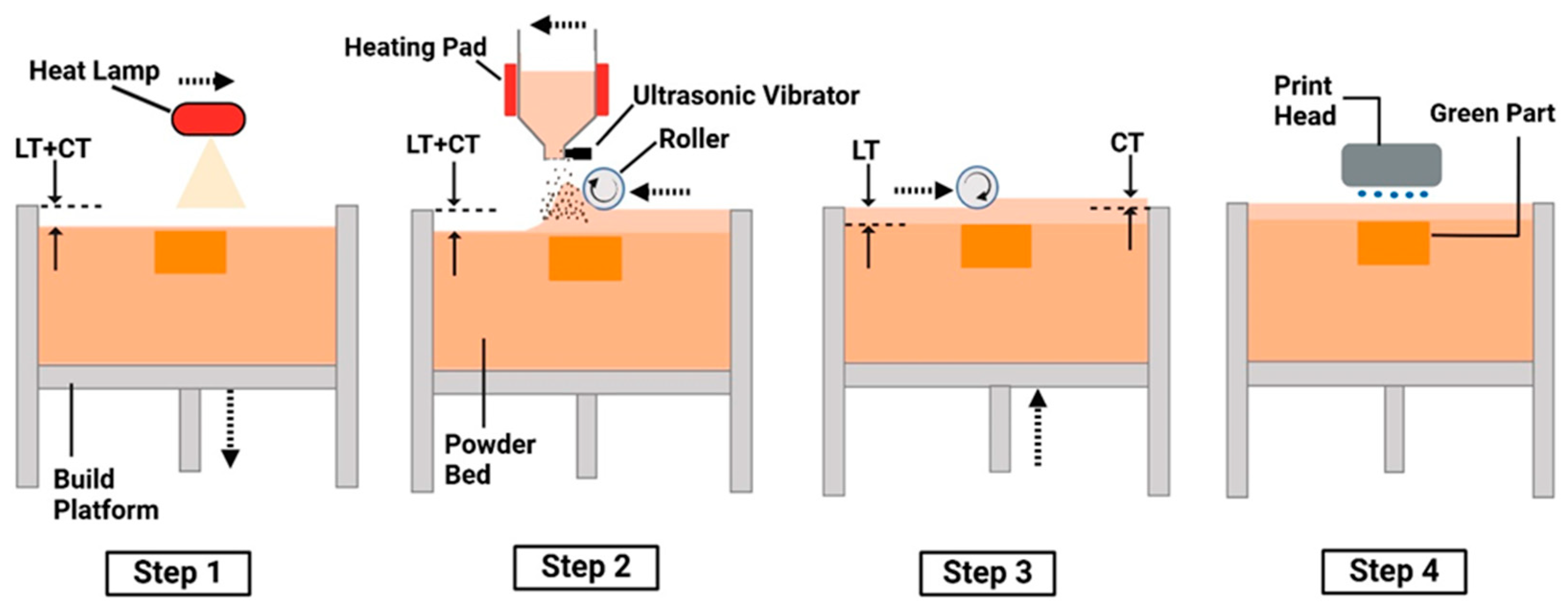
2.2. Binder Jetting 3D Printing of SiC Preforms

In this study, a silicon carbide (SiC) preform refers to the green part printed using a binder jetting 3D printer (Innovent+, ExOne Company, Irwin, PA, USA) with an aqueous binder (BA005, ExOne Company). Creo parametric v 9.0, Boston, MA, USA, served as the CAD (computer-aided design) software used to create the 3D model of the preform, with dimensions of 10 mm (length) × 10 mm (width) × 4 mm (thickness). The same CAD software was also used to generate the STL file of the designed model. The STL file was processed to generate machine-readable instructions that directed the operation of the binder jetting 3D printer [22].
Figure 1 illustrates the fundamental steps of binder jetting with powder bed compaction [15]. In Step 1, the build platform lowers by a distance equal to the sum of the layer thickness (LT) and compaction thickness (CT), and a heat lamp moves across the powder bed from left to right to dry the powder. In Step 2, the hopper dispenses powder moving from right to left, while a counter-rotating roller spreads the powder in the same direction. In Step 3, the build platform rises by a distance equal to CT, and the roller compacts the powder layer by moving from left to right. In Step 4, the print head deposits liquid binder onto designated regions of the powder bed based on a 3D model. These steps repeat until the entire part is printed.
The printing parameters and their values used in this study are listed in Table 1. Definitions of these parameters can be found in the literature [23]. These parameter values were chosen after conducting preliminary trials, yielding SiC preforms with no observable defects (more information on the defects will be provided in Section 3).

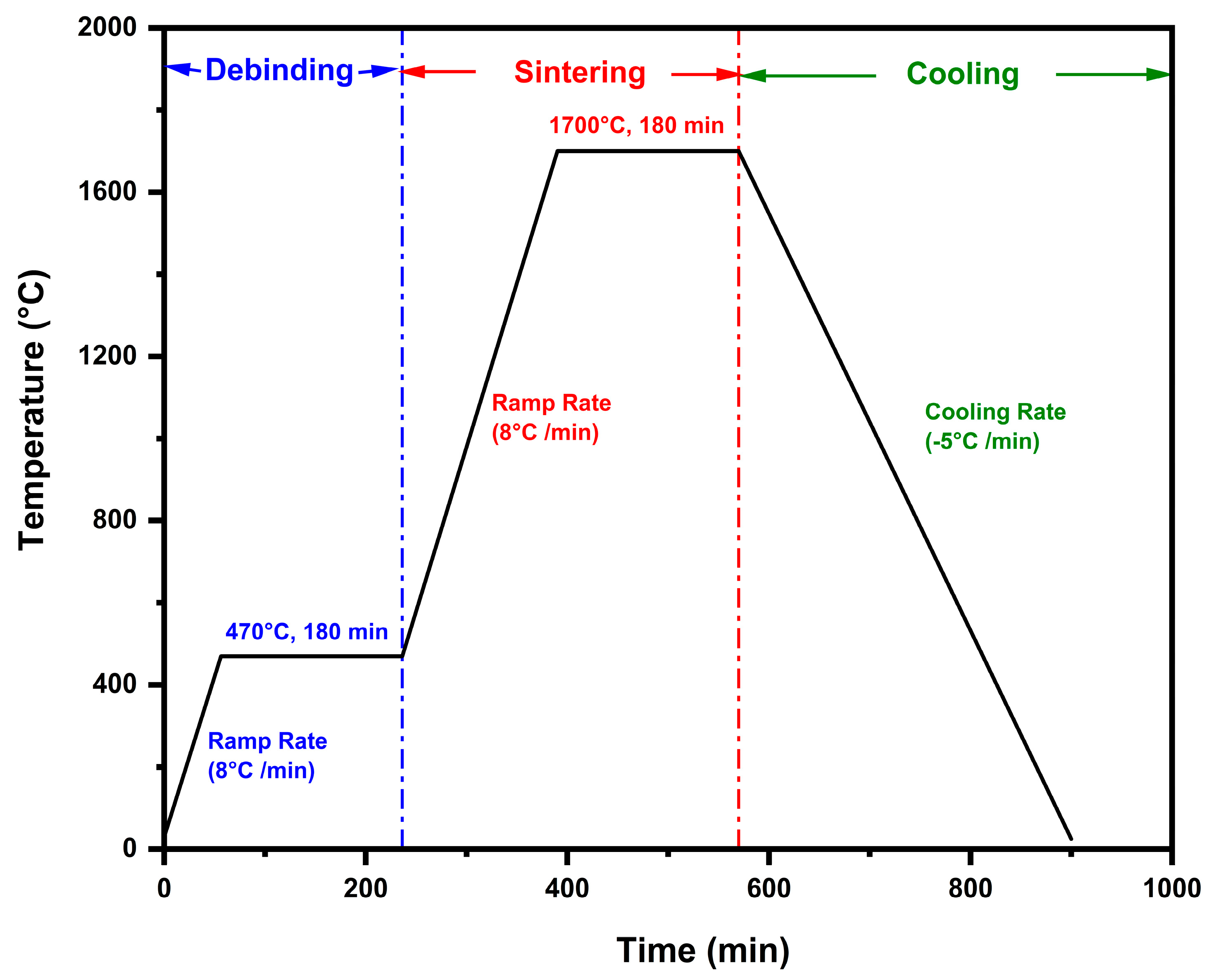
2.3. Post-Printing Steps (Curing, Depowdering, Debinding, and Sintering) Prior to Infiltration

After printing, the build platform containing the printed SiC preforms was detached from the printer and placed in an oven (DX402C, Yamato Scientific, Tokyo, Japan) at 125 °C for 5 h to cure the binder in the printed preforms [24]. This curing process was essential to provide the printed SiC preforms with sufficient mechanical strength. After curing, the preforms were removed from the build platform, and depowdering was performed by gently brushing off any loose powder from their surfaces using a soft brush [15,25].
The debinding and sintering of printed SiC preforms were conducted using a box furnace (KSL-1750X-KA3, MTI Corporation, Richmond, CA, USA). The debinding and sintering cycles for the SiC preforms are shown in Figure 2. The furnace temperature was initially increased from room temperature (20 °C) to 470 °C at a rate of 8 °C per minute [26]. The temperature was then held at 470 °C for 180 min to ensure complete binder removal. After debinding, the furnace temperature was ramped up to 1700 °C at the rate of 8 °C per minute. The furnace temperature was maintained at 1700 °C for 180 min to sinter the preforms. Upon completion of sintering, the furnace was cooled to room temperature at a rate of ~5 °C per minute.

2.4. Infiltration of SiC Preforms with Aluminum

Initially, an Al+Mg mixed powder (at the ratio of 92:8 by weight) was added to a ceramic crucible. A sintered SiC preform was placed inside the crucible and completely buried in the Al+Mg mixed powder. Then, the crucible, along with the Al+Mg mixed powder and sintered SiC preform, was placed inside a tube furnace (Thermo Scientific Lindberg Blue M). The tube furnace was then heated to 1000 °C at the rate of 10 °C/min and held at 1000 °C for 120 min under the pressure of 25 psi in the N2 environment. During heating, the Mg in the powder enhanced the wettability of Al [27], facilitating Al infiltration into the sintered SiC preform.

2.5. Characterization Techniques

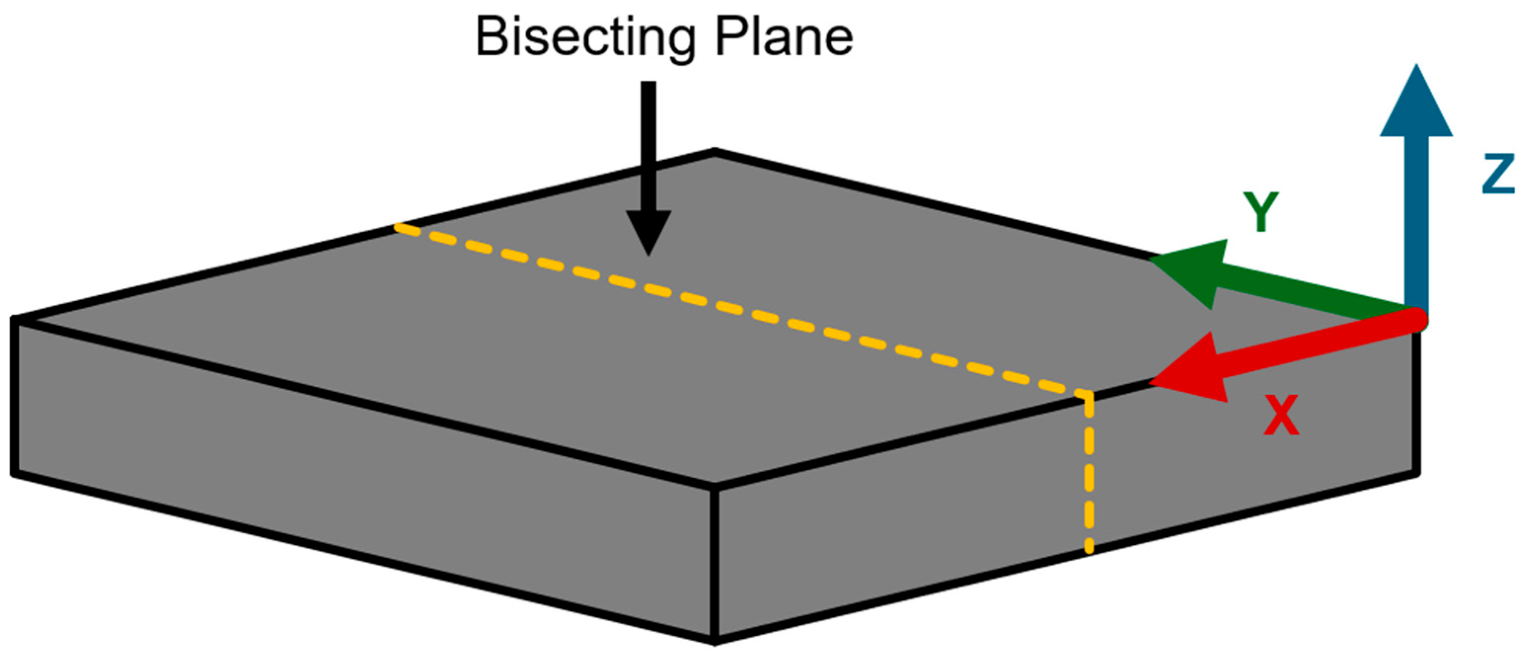
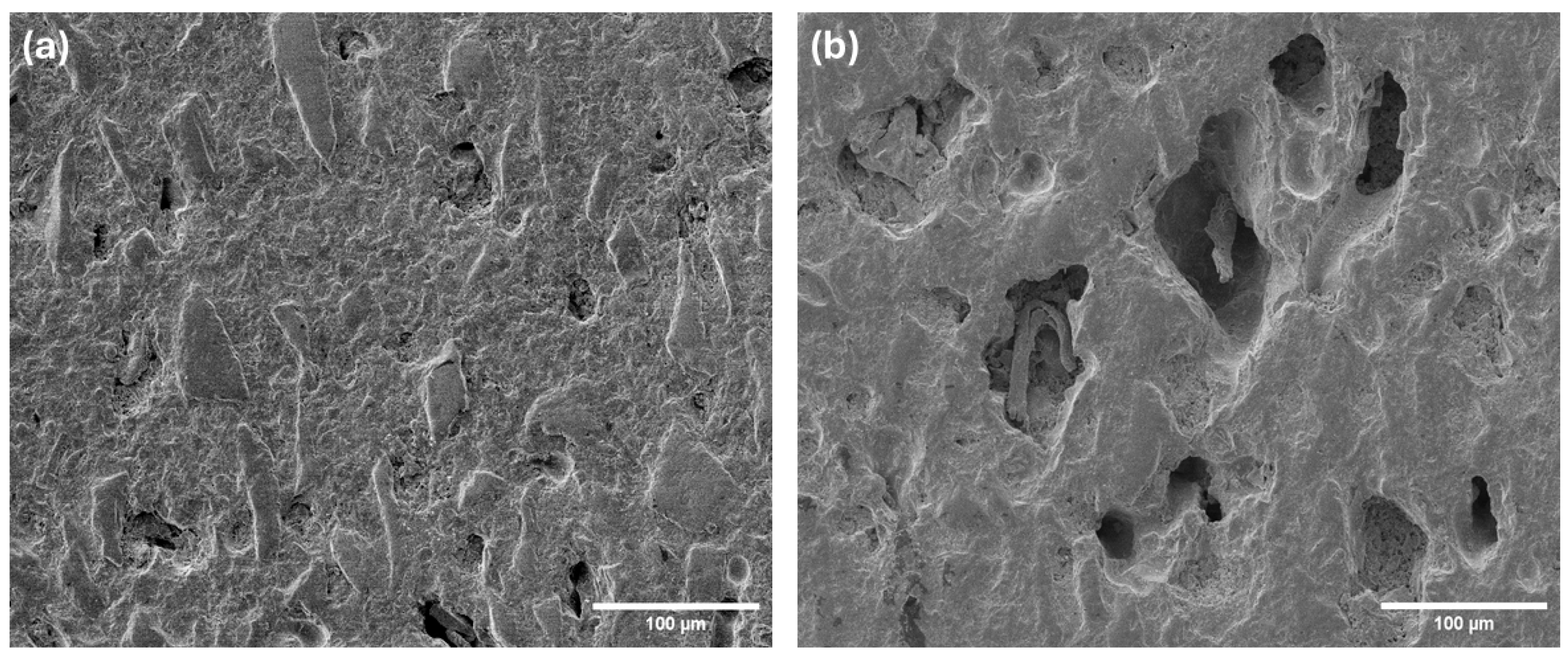
2.5.1. Cross-Sectional Imaging of SiC Preform After Infiltration

To prepare the sample for cross-sectional imaging, the infiltrated SiC preform was bisected along the Y-Z plane (as shown in Figure 3) where the Z-axis is the print direction (thickness), the X-axis is the powder spread direction, and the Y-axis is perpendicular to the X-Z plane. The SiC preform was buried in the Al+Mg mixed powder during infiltration. It was expected that the infiltration took place in all directions. Cross-sectional images of the infiltrated SiC preform were captured using an iPhone 15 Pro Max.
Cross-sectional SEM images of the infiltrated preform were also taken at a magnification of 100×. To prepare the cross-sectional surface for SEM imaging, the cross-sectioned surface of the infiltrated preform was polished using the standard metallurgical method as described in the literature [28], and coated with a 5 nm layer of platinum to enhance conductivity. Field emission scanning electron microscopy (FE-SEM, JSM7500, JEOL, Tokyo, Japan, RRID: SCR_022202) was used to capture microstructural images.

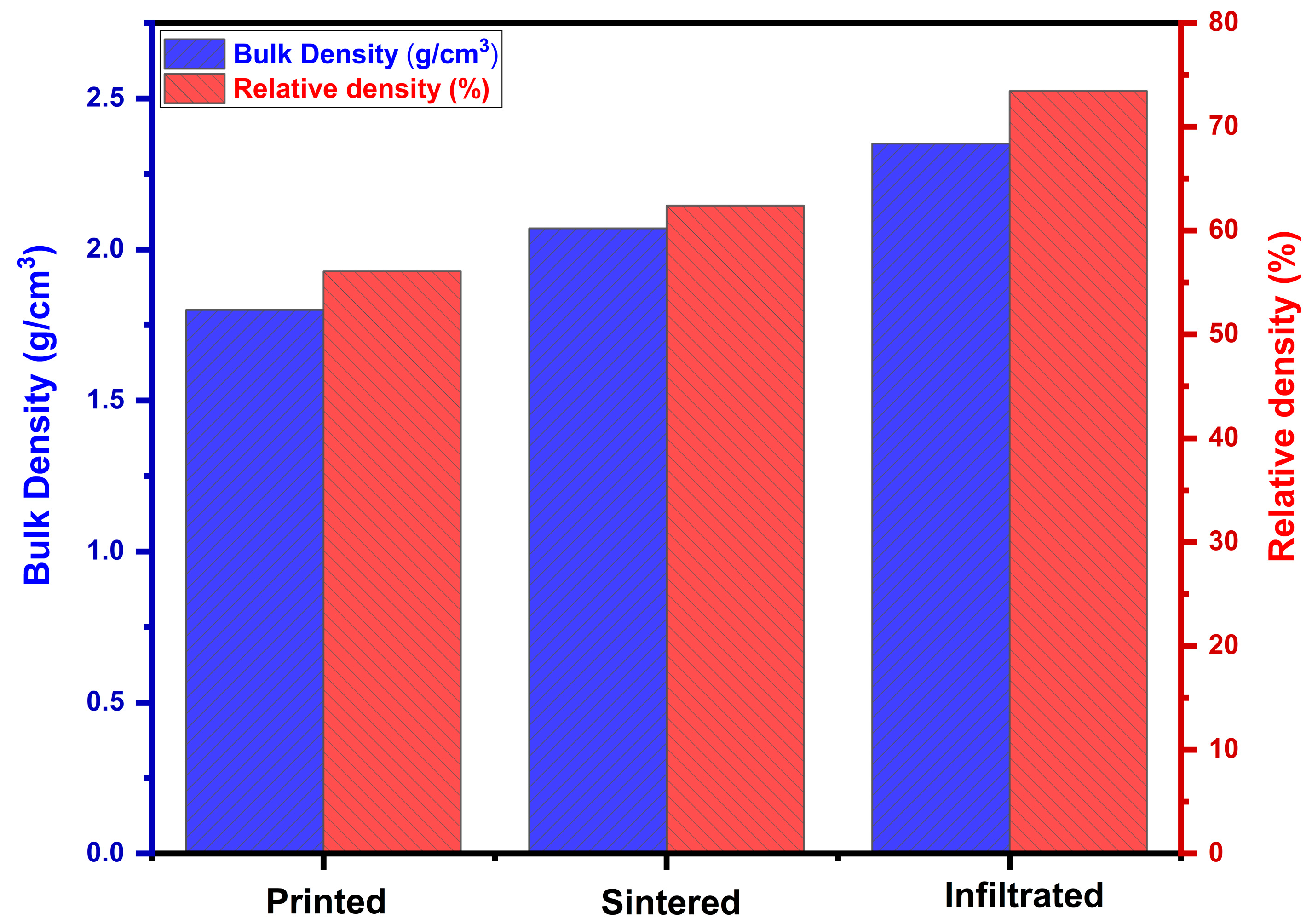
2.5.2. Density Measurement

The green density ρ of printed SiC preforms was determined through geometrical and mass measurements. The Archimedes’ method [29] is preferred in density measurement. However, in this study, the green parts were fragile and porous. Immersing them in water, as required by the Archimedes’ method, could damage or alter their structure. Thus, the geometric method [30] was used to measure green part density. A slide caliper (500-196-30 Digimatic 0-6’’/150 MM Stainless Steel Digital Caliper, Mitutoyo, Japan) was used to measure the length, width, and thickness of the printed SiC preforms. A weight scale with a 0.001 g resolution was used to measure their mass. The green density was then calculated using Equation (1), where m represents the mass, and l , w , and t denote the length, width, and thickness, respectively.
G r e e n   d e n s i t y   ρ = m / l × w × t
The Archimedes method [31] was used to determine the bulk density of the infiltrated SiC preforms. Using ISO 18754, bulk density can be calculated using Equation (2).
ρ = ρ w m d m w m s
where ρ is the bulk density of the preform, ρ w is the density of water, m d is the dry mass of the preform, m w is the wet mass of the preform, and m s is the mass of the preform while submerged in water.
The relative density of the infiltrated preforms was calculated as the ratio of the measured bulk density to the theoretical density of SiC. The theoretical density of SiC is the mass of the atoms in a unit cell divided by the volume of the unit cell. The theoretical density of SiC is 3.21 g/cm3 and was obtained from the literature [32]. The theoretical density of SiC was used in the calculation of the relative density of the preform after printing, sintering, and infiltration. It is noted that the relative density calculated this way was not accurate for the infiltrated preform because the infiltrated preform contained not only SiC but also aluminum and magnesium. Since the content of aluminum and magnesium in the preform was not determined in this study, it was not possible to accurately calculate the relative density of the infiltrated preform.

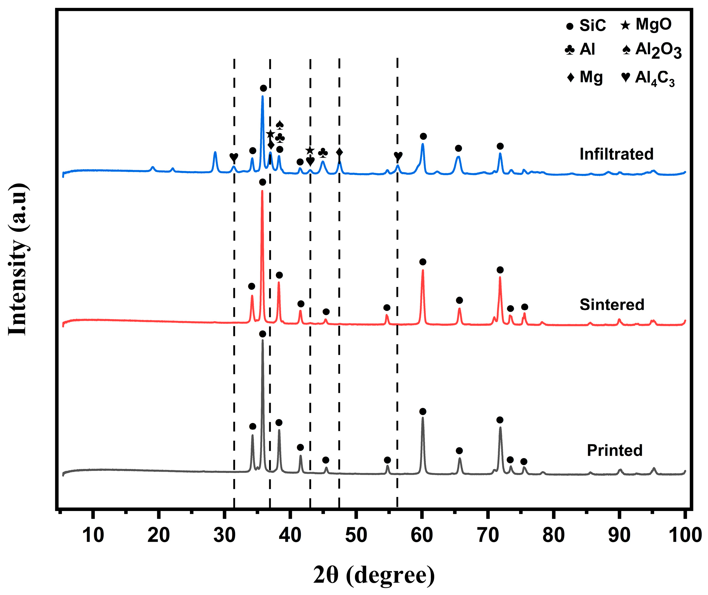
2.5.3. Detection of Presence of Aluminum in SiC Preforms Using X-Ray Diffraction

X-ray diffraction analysis of the printed, sintered, and infiltrated preforms was performed using a D8 Discover diffractometer (BRUKER, Billerica, MA, USA), equipped with a Vantec 500 2D detector. The instrument operated at a power setting of 40 kV and 40 mA, utilizing a copper source with a characteristic wavelength of 1.54056 Å. Data acquisition was conducted over a 2θ range from 5° to 100°. The peaks of the phases were identified using the Inorganic Crystal Structure Database (ICSD) [33].

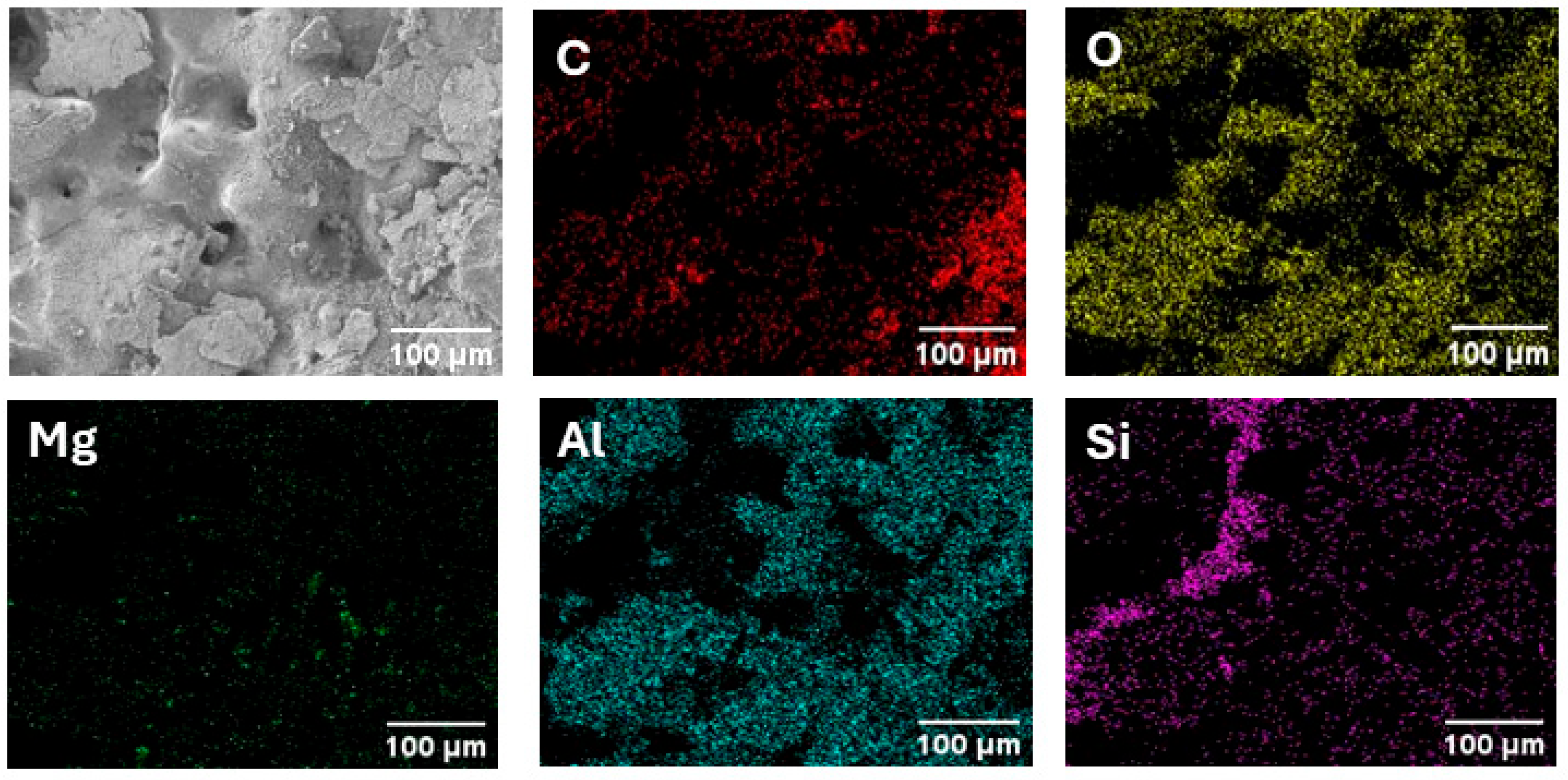
2.5.4. Composition Analysis Using Energy-Dispersive X-Ray Spectroscopy (EDS)

On the cross-sectional surface of the infiltrated preform polished using the standard metallurgical method as described in the literature [28], composition analysis of infiltrated preform was conducted using an Oxford energy-dispersive X-ray spectroscopy (EDS) system integrated with a field emission scanning electron microscope (FE-SEM) (JEOL JSM-7500F, Tokyo, Japan).

3. Results and Discussion

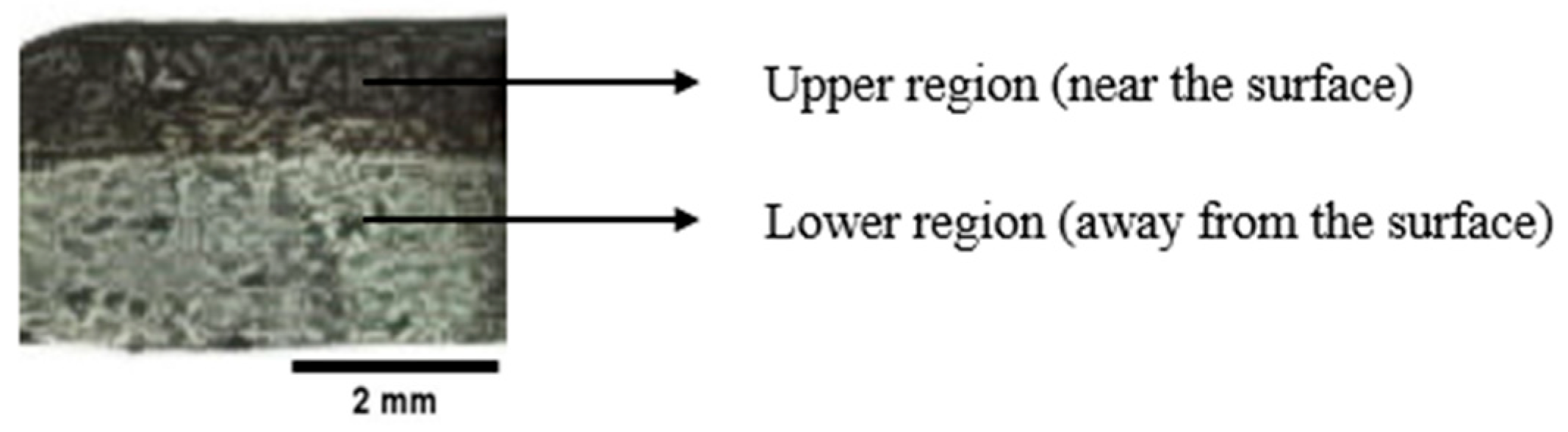
3.1. Cross-Sectional Image of Infiltrated SiC Preform

Figure 4 shows the cross-sectional image of the infiltrated preform. It shows that the surface looks darker in the upper region of the cross-section of the infiltrated preform, implying that infiltration occurred in this region. This speculation is substantiated by the SEM images of the cross-section.
The SEM images in Figure 5 show the microstructure of infiltrated SiC preform. These SEM images were taken in the upper region and lower region of the cross-sectional surface of the infiltrated preform shown in Figure 4. The SEM image taken in the upper region, shown in Figure 5a, has mostly filled pores with only a few remaining voids, confirming successful aluminum infiltration. The SEM image taken in the lower region, shown in Figure 5b, contains large, irregularly shaped pores, suggesting incomplete aluminum infiltration.
The incomplete infiltration is likely due to the high compaction during printing, which created a dense green preform, and the high sintering temperature of 1700 °C, which increased the bulk density of the sintered preform. These factors restricted the flow of the Al+Mg mixed powder through the entire SiC matrix.

3.2. Density

Figure 6 shows the bulk density and relative density of printed SiC preform, sintered SiC preform, and infiltrated SiC preform. The green density (about 1.8 g/cm3) and relative density (56.07%) of the printed preform were lower than those of the sintered preform and the infiltrated preform. This is due to the high porosity and the presence of binder materials. The relative density of the printed preform was calculated without considering the binder content in the printed preform. When measuring the bulk density of the printed preform, the weight of the printed preform included the weight of the binder inside the preform. This method is widely used in the literature when measuring the density of green parts printed by binder jetting [30,34]. After debinding, the bulk density increases to about 2.07 g/cm3, with a relative density of 62.31%. This increase happens because the binder is removed, and the sintering process partially densifies the SiC preform by reducing open porosity. Following aluminum infiltration at 1000 °C, the bulk density rises further to approximately 2.36 g/cm3, with a relative density of 73.44%.

3.3. Composition

Figure 7 shows X-ray diffraction (XRD) patterns of printed preform, sintered preform, and infiltrated preform. The printed preform displays peaks corresponding solely to SiC, indicating the presence of the base material with no additional phases. After sintering, the XRD pattern remains dominated by SiC peaks, suggesting that sintering does not introduce any significant phase changes. After aluminum infiltration, additional peaks associated with aluminum and magnesium appear prominently in the XRD pattern. The aluminum peaks were particularly evident at 2θ values of around 38.19° and 44.82°. A peak observed at 2θ value of 38.19° aligns closely with the reference peak for Al2O3 (at 2θ value of 37.80° [33]). Peaks at 2θ values of 31.34°, 42.89°, and 56.21° confirm the presence of Al4C3. Peaks observed at 2θ values of 36.8° and 47.44° confirm the presence of Mg, while peaks at 36.8° and 42.89° confirm the presence of MgO. For easy observations, dotted vertical lines are added at 2θ values of 31.34°, 36.8°, 42.89°, 47.44°, and 56.21°.
Figure 8 shows the elemental mapping of the infiltrated SiC preform in the upper region of the cross-section shown in Figure 5. The mapping highlights the distribution of key elements: carbon (C), oxygen (O), magnesium (Mg), aluminum (Al), and silicon (Si). Aluminum is present in the upper region of the infiltrated preform. Carbon and silicon are prominently distributed, representing the SiC matrix. Oxygen is observed in small amounts, likely due to minor surface oxidation during processing. A small amount of magnesium was detected because the infiltration process used a powder mixture consisting of 92% aluminum and 8% magnesium by weight. The elemental mapping demonstrates successful aluminum penetration in the upper region of the sintered SiC preform.

4. Conclusions

This study demonstrates the feasibility of fabricating SiC–aluminum composites through binder jetting 3D printing and subsequent aluminum infiltration. The bulk density of the printed preform is increased by 15% after sintering and increased by 31% after infiltration. Visual inspection of the cross-section surface revealed that infiltration was localized to the upper region of the cross-section of the infiltrated preform. SEM images revealed that the upper region predominantly contained filled pores with only a few remaining voids, while the lower region exhibited large, irregularly shaped pores, indicating incomplete aluminum infiltration. Characterization using X-ray diffraction (XRD) and energy-dispersive X-ray spectroscopy (EDS) confirmed the successful incorporation of aluminum into the SiC matrix.
Further research will focus on improving infiltration depth by exploring various approaches, including optimizing sintering parameters (such as temperature and time) and infiltration parameters (such as pressure, particle size of aluminum powder, as well as the ratio of aluminum powder and magnesium powder). Future research will also be conducted to understand the effects of SiC powder characteristics (e.g., particle size and distribution) and printing parameters (such as layer thickness and compaction thickness in binder jetting). In addition, in future studies, performance tests will be conducted based on the application field of the SiC–aluminum metal matrix composite, including measurements of compressive strength and hardness of the infiltrated preforms.

Author Contributions

Conceptualization, F.K. and Z.P.; methodology, F.K. and M.S.A.; software, F.K.; validation, F.K., M.S.A., J.S. and Z.P.; formal analysis, F.K. and M.S.A.; investigation, F.K., M.S.A., J.S. and M.M.P.; resources, F.K., Z.P. and S.K.; data curation, F.K. and Z.P.; writing—original draft preparation, F.K. and J.S.; writing—review and editing, F.K., J.S., M.S.A., M.M.P., Z.P. and S.K.; visualization, F.K.; supervision, Z.P. All authors have read and agreed to the published version of the manuscript.

Funding

This research received no external funding.

Data Availability Statement

Data are available upon reasonable request made to the authors.

Conflicts of Interest

Author Stephen Kachur was employed by the company CPS Technologies Corp. The remaining authors declare that the research was conducted in the absence of any commercial or financial relationships that could be construed as a potential conflict of interest.

References

  1. Chen, L.-Y.; Qin, P.; Zhang, L.; Zhang, L.-C. An overview of additively manufactured metal matrix composites: Preparation, performance, and challenge. Int. J. Extrem. Manuf. 2024, 6, 052006. [Google Scholar] [CrossRef]
  2. Ghinatti, E.; Bertolini, R.; Sorgato, M.; Ghiotti, A.; Bruschi, S. Tool wear and surface finish analysis after drilling Al-SiC metal matrix composite with DLC-coated tools at varying feed. Procedia CIRP 2024, 123, 53–58. [Google Scholar] [CrossRef]
  3. Monazzah, A.H.; Pouraliakbar, H.; Bagheri, R.; Reihani, S.M.S. Al-Mg-Si/SiC laminated composites: Fabrication, architectural characteristics, toughness, damage tolerance, fracture mechanisms. Compos. Part B Eng. 2017, 125, 49–70. [Google Scholar] [CrossRef]
  4. An, Q.; Cong, X.S.; Shen, P.; Jiang, Q.C. Roles of alloying elements in wetting of SiC by Al. J. Alloys Compd. 2019, 784, 1212–1220. [Google Scholar] [CrossRef]
  5. Gutema, E.M.; Lemu, H.G. Conventional Machining of Metal Matrix Composites towards Sustainable Manufacturing—Present Scenario and Future Prospects. J. Compos. Sci. 2024, 8, 356. [Google Scholar] [CrossRef]
  6. Hashim, J.; Looney, L.; Hashmi, M.S.J. The enhancement of wettability of SiC particles in cast aluminium matrix composites. J. Mater. Process. Technol. 2001, 119, 329–335. [Google Scholar] [CrossRef]
  7. Song, X.-Y.; Shu, S.-L.; Zhang, S.; Yang, H.-Y.; Qiu, F.; Jiang, Q.-C. Microstructure, solidification defects and mechanical properties of high-modulus and high-strength SiC/AlSi10Mg composites fabricated by selective laser melting. Ceram. Int. 2024, 50, 26607–26623. [Google Scholar] [CrossRef]
  8. Shetty, A.; Bhat, T.; Sharma, S.; Hegde, A.K.N.; Prabhu, R.; Anne, G. Effects of Magnesium Content and Age Hardening Parameters on the Hardness and Ultimate Tensile Strength of SiC-Reinforced Al-Si-Mg Composites. J. Compos. Sci. 2024, 9, 5. [Google Scholar] [CrossRef]
  9. Jayashree, P.; Sharma, S.; Kumar, S.; Bangera, M.; Bhat, R. Tension and Impact Analysis of Tungsten Inert Gas Welded Al6061-SiC Composite. J. Compos. Sci. 2023, 7, 78. [Google Scholar] [CrossRef]
  10. Wang, H.; Zhang, R.; Hu, X.; Wang, C.-A.; Huang, Y. Characterization of a powder metallurgy SiC/Cu–Al composite. J. Mater. Process. Technol. 2008, 197, 43–48. [Google Scholar] [CrossRef]
  11. Sadhu, K.K.; Mandal, N.; Sahoo, R.R. SiC/graphene reinforced aluminum metal matrix composites prepared by powder metallurgy: A review. J. Manuf. Process. 2023, 91, 10–43. [Google Scholar] [CrossRef]
  12. Ghinatti, E. Ultrasonic Vibration Assisted Turning for Reducing Tool Wear in Metal Matrix Composite Machining; University of Padua: Padua, Italy, 2021. [Google Scholar]
  13. Liu, J.; Zheng, Z.; Wang, J.; Wu, Y.; Tang, W.; Lü, J. Pressureless infiltration of liquid aluminum alloy into SiC preforms to form near-net-shape SiC/Al composites. J. Alloys Compd. 2008, 465, 239–243. [Google Scholar] [CrossRef]
  14. Polozov, I.; Razumov, N.; Masaylo, D.; Silin, A.; Lebedeva, Y.; Popovich, A. Fabrication of silicon carbide fiber-reinforced silicon carbide matrix composites using binder jetting additive manufacturing from irregularly-shaped and spherical powders. Materials 2020, 13, 1766. [Google Scholar] [CrossRef] [PubMed]
  15. Wang, Y.; Zhao, Y.F. Investigation of sintering shrinkage in binder jetting additive manufacturing process. Procedia Manuf. 2017, 10, 779–790. [Google Scholar] [CrossRef]
  16. Bai, Y.; Wagner, G.; Williams, C.B. Effect of particle size distribution on powder packing and sintering in binder jetting additive manufacturing of metals. J. Manuf. Sci. Eng. 2017, 139, 081019. [Google Scholar] [CrossRef]
  17. Yu, T.; Zhao, Z.; Li, J. Effect of sintering temperature and sintering additives on the properties of alumina ceramics fabricated by binder jetting. Ceram. Int. 2023, 49, 9948–9955. [Google Scholar] [CrossRef]
  18. Do, T.; Kwon, P.; Shin, C.S. Process development toward full-density stainless steel parts with binder jetting printing. Int. J. Mach. Tools Manuf. 2017, 121, 50–60. [Google Scholar] [CrossRef]
  19. Snelling, D.A.; Williams, C.B.; Suchicital, C.T.; Druschitz, A.P. Binder jetting advanced ceramics for metal-ceramic composite structures. Int. J. Adv. Manuf. Technol. 2017, 92, 531–545. [Google Scholar] [CrossRef]
  20. Zulfia, A.; Hand, R. The production of Al-Mg alloy/SiC metal matrix composites by pressureless infiltration. J. Mater. Sci. 2002, 37, 955–961. [Google Scholar] [CrossRef]
  21. Kunchala, P.; Kappagantula, K. 3D printing high density ceramics using binder jetting with nanoparticle densifiers. Mater. Des. 2018, 155, 443–450. [Google Scholar] [CrossRef]
  22. Pasha, M.M.; Arman, M.S.; Khan, F.; Pei, Z.; Kachur, S. Effects of Layer Thickness and Compaction Thickness on Green Part Density in Binder Jetting Additive Manufacturing of Silicon Carbide: Designed Experiments. J. Manuf. Mater. Process. 2024, 8, 148. [Google Scholar] [CrossRef]
  23. Mostafaei, A.; Elliott, A.M.; Barnes, J.E.; Li, F.; Tan, W.; Cramer, C.L.; Nandwana, P.; Chmielus, M. Binder jet 3D printing—Process parameters, materials, properties, modeling, and challenges. Prog. Mater. Sci. 2021, 119, 100707. [Google Scholar] [CrossRef]
  24. Gonzalez, J.; Mireles, J.; Lin, Y.; Wicker, R.B. Characterization of ceramic components fabricated using binder jetting additive manufacturing technology. Ceram. Int. 2016, 42, 10559–10564. [Google Scholar] [CrossRef]
  25. Khan, F.; Arman, M.S.; Sanders, J.; Pasha, M.M.; Rahman, A.M.; Pei, Z.; Dong, T. Binder Jetting 3D Printing Utilizing Waste Algae Powder: A Feasibility Study. Intell. Sustain. Manuf. 2024, 1, 10016. [Google Scholar] [CrossRef]
  26. Porter, Q.; Moghadasi, M.; Pei, Z.; Ma, C. Dense and strong ceramic composites via binder jetting and spontaneous infiltration. Ceram. Int. 2023, 49, 17363–17370. [Google Scholar] [CrossRef]
  27. Aguilar-Martinez, J.; Hernandez, M.; Castillo-Torres, J.; Pech-Canul, M. Effect of particle size and Mg content on the processing parameters of Al-Si-Mg/SiCp composites processed by pressureless infiltration. Rev. Mex. Física 2007, 53, 198–204. [Google Scholar]
  28. Täffner, U.; Carle, V.; Schäfer, U.; Hoffmann, M.J. Preparation and Microstructural Analysis of High-Performance Ceramics. In Metallography and Microstructures; ASM International: Almere, The Netherlands, 2004; pp. 1057–1066. [Google Scholar]
  29. Spierings, A.B.; Schneider, M.U.; Eggenberger, R. Comparison of density measurement techniques for additive manufactured metallic parts. Rapid Prototyp. J. 2011, 17, 380–386. [Google Scholar] [CrossRef]
  30. Paudel, B.J.; To, A.C. Spatial green density variation and its effect on distortion prediction in binder jet additive manufacturing. Addit. Manuf. 2025, 98, 104640. [Google Scholar] [CrossRef]
  31. ISO 18754:2013; Fine ceramics (Advanced Ceramics, Advanced Technical Ceramics)-Determination of Density and Apparent Porosity. ISO: Geneva, Switzerland, 2013.
  32. Vaßen, R.; Kaiser, A.; Förster, J.; Buchkremer, H.; Stöver, D. Densification of ultrafine SiC powders. J. Mater. Sci. 1996, 31, 3623–3637. [Google Scholar] [CrossRef]
  33. ICSD. Inorganic Crystal Structure Database. 1913. Available online: https://icsd.products.fiz-karlsruhe.de/en/about/about-icsd (accessed on 24 January 2025).
  34. Miyanaji, H.; Rahman, K.M.; Da, M.; Williams, C.B. Effect of fine powder particles on quality of binder jetting parts. Addit. Manuf. 2020, 36, 101587. [Google Scholar] [CrossRef]
Figure 1. Four steps in binder jetting using powder bed compaction (layer thickness is represented by LT, and compaction thickness is represented by CT) [22].
Jcs 09 00111 g001
Figure 2. Debinding and sintering cycle of the box furnace for SiC preforms.
Jcs 09 00111 g002
Figure 3. A bisecting plane parallel to the Y-Z plane of the printed preform.
Jcs 09 00111 g003
Figure 4. Cross-sectional image of infiltrated SiC preform.
Jcs 09 00111 g004
Figure 5. SEM images of the cross-sectional surface of the infiltrated preform in (a) the upper region and (b) the lower region.
Jcs 09 00111 g005
Figure 6. Bulk density and relative density of the printed preform, sintered preform, and infiltrated preform.
Jcs 09 00111 g006
Figure 7. XRD patterns of printed preform, sintered preform, and infiltrated preform.
Jcs 09 00111 g007
Figure 8. Elemental mapping indicates the presence of aluminum (Al) in the infiltrated preform.
Jcs 09 00111 g008
Table 1. Printing parameters and their values used in binder jetting 3D printing.
Printing ParameterValue
Layer thickness (µm)45
Compaction thickness (µm)35
Ultrasonic intensity (%)100
Roller traverse speed (mm/s)15
Roller rotation speed (rpm)300
Roughening roller rotation speed (rpm)50
Binder saturation (%)60
Binder set time (s)30
Bed temperature (°C)50
Drying time (s)15
Packing rate (%)50
Disclaimer/Publisher’s Note: The statements, opinions and data contained in all publications are solely those of the individual author(s) and contributor(s) and not of MDPI and/or the editor(s). MDPI and/or the editor(s) disclaim responsibility for any injury to people or property resulting from any ideas, methods, instructions or products referred to in the content.

