Article

Transfer the Sulfate Environment into a Beneficial Factor: Performance Enhancement and Mechanism of Electrolytic Manganese Residue-Based Mine Filling Materials

1
Power Construction Corporation of China Guiyang Engineering Corporation Limited, Guiyang 550081, China
2
School of Civil Engineering, Central South University, Changsha 410075, China
*
Author to whom correspondence should be addressed.
J. Compos. Sci. 2025, 9(12), 642; https://doi.org/10.3390/jcs9120642
Submission received: 26 September 2025 / Revised: 14 November 2025 / Accepted: 17 November 2025 / Published: 25 November 2025
(This article belongs to the Section Composites Applications)

Abstract

This paper presents a dual-benefit method for green and sustainable mine construction through developing filling materials using solid waste. In practical engineering applications, there are sulfate ions in mine water, which leads to performance degradation in traditional cement-based filling materials. In this paper, electrolytic manganese slag-based mine filling materials (EBFMs) were developed by utilizing electrolytic manganese residue (EMR), fly ash (FA), phosphorus slag (PS), and quicklime (QL). The effects of EMR content on the basic performance and the sulfate resistance of EBFM in a 5 wt.% Na2SO4 solution at different stages of erosion were extensively discussed. The results showed that when the content of EMR was 25 wt.%, EBFM showed the best basic performance and sulfate resistance among all groups. After sulfate erosion, the compressive strength increased and the porosity decreased, and the mass of the samples increased. The EBFM exhibited superior sulfate corrosion resistance at the lowest porosity (4.14%) and the highest mass change rate (5.82%) after 90 days of sulfate erosion. The corrosion resistance coefficient stabilized between 1.23 and 1.24 after 30 days of erosion. In a sulfate environment, sulfate ions contribute to promoting hydration reactions to form more hydration products, which make a denser structure. The Fe-AFt (ferrous ettringite) formed during hydration demonstrates superior stability, representing a key factor for better sulfate resistance. The EBFM transformed the presence of sulfate ions in mine water (a typically adverse condition) into a beneficial factor that enhanced the materials’ performance, thereby exhibiting excellent sulfate resistance.

1. Introduction

Underground mining frequently results in the formation of voids, which can lead to serious hazards such as water inrush and ground collapse [1,2]. These risks pose serious threats to both public safety and the secure operation of mines, so it is necessary to implement appropriate measures to address risks in underground mined-out areas. Mine filling is a widely adopted technique for the treatment of underground mined-out areas, as it can effectively control ground pressure and prevent surface subsidence [3]. However, the high cost of conventional backfilling materials remains a constraint on their wide application [4]. Utilizing industrial solid waste to produce mine backfilling materials offers an effective approach to reducing the cost of mine filling [5].
The partial or complete replacement ordinary Portland cement with industrial solid waste can effectively reduce the cost of backfilling materials [6,7]. Preparing cementitious materials with solid waste has attracted increasing attention from scholars to prepare cementitious materials by solid waste [8,9,10,11]. Chu et al. [12] prepared mine backfilling materials using carbide slag, iron tailings, river sediment, and cement as raw materials. Wu et al. [13] employed phosphogypsum and cement to prepare filling materials, which decreased the usage of Portland cement in the application. Cementitious materials have good mechanical performance and meet the performance requirements for engineering applications of mine backfilling materials. He et al. [14] prepared a cementitious material with good fluidity by combining cement, fly ash and lithium slag, achieving a 28 d compressive strength of 2.28 MPa. Phosphogypsum and fly ash from municipal solid waste incineration could also be utilized to produce construction filling materials, with a 7 d compressive strength of 4 MPa [15]. Deng et al. [6] replaced cement with ground granulated blast-furnace slag, resulting in a 28 d compressive strength reaching between 1.5 MPa and 2 MPa.
Additionally, cementitious materials also exhibit excellent volume stability. Liu et al. [16,17] utilized the early-stage slightly expansive behavior of gypsum to offset the shrinkage caused by aluminosilicate materials, resulting in the development of high-performance geopolymers. The proper addition of sulfate-rich materials in appropriate amounts can effectively improve the shrinkage performance of cementitious materials and help maintain volume stability [18,19]. Meanwhile, the hydration products in cementitious materials prepared by solid waste can effectively stabilize hazardous ions through physical adsorption and chemical bonding, thereby reducing the leaching of hazardous ions. Bai et al. [20] demonstrated that geopolymer binders could be synthesized from municipal solid waste incineration fly ash, red mud, and carbide slag. These exhibited favorable mechanical properties and effectively stabilized hazardous ions, indicating significant environmental benefits. In conclusion, the utilization of solid waste in the development of backfilling materials presents considerable benefits in terms of cost reduction, environmental sustainability and materials’ performance. In the process of preparing cementitious materials from solid waste, it is essential to ensure the presence of sufficient calcium and aluminosilicate-rich active components, which are activated by sulfates and alkaline substances, leading to the formation of hydration products that contribute to strength development.
As an industrial byproduct of metallic manganese production [19,21], EMR is an acidic solid waste rich in silicates and gypsum [22], which can be used as a potential sulfate activator for the preparation of cementitious materials [23]. The application of backfill materials prepared from EMR in engineering practice can not only significantly reduce the stockpile of electrolytic manganese residue, but help mitigate the environmental hazards associated with its storage [24]. Wang et al. [25] prepared backfill materials primarily using EMR, GGBS and RM, with sodium hydroxide as the activator. When the content of EMR was 20 wt.%, the 28 d compressive strength of the backfill materials reached a maximum of 11.04 MPa. Lan et al. [26] prepared the specimens by utilizing EMR as the raw material under the activation of MgO and CaHPO4·2H2O, which exhibited a 28-day compressive strength of 19.70 MPa and achieved an ammonia nitrogen immobilization efficiency of 98.79%, meeting the engineering requirements for backfilling. Similarly, Zhang et al. [27] developed subgrade materials by synergistically employing red mud, carbide slag and GGBS with EMR, which demonstrated excellent mechanical performance and effective immobilization of manganese ions. All of the above reveal that the materials prepared by EMR meet the requirement of mechanical properties and environment.
However, in practical mine backfilling environments, the performance of backfilling materials is greatly influenced by the presence of sulfates in mine water. Li et al. [28] reported that sulfates inhibit and delay the early hydration process of cement, while high sulfate concentrations exacerbate pore connectivity, ultimately leading to a reduction in compressive strength. Bondar et al. [29,30] found that after one year of immersion in a 5 wt.% Na2SO4 solution, alkali-activated slag concrete showed a smaller decrease in compressive strength compared to ordinary Portland cement (OPC) concrete. Komljenović et al. [31] also found that the corrosion resistance coefficient of OPC decreased to 0.90 after 90 days of sulfate erosion. Sulfate attack can cause severe deterioration of the filling materials, leading to structural instability and cracks. Therefore, it is necessary to investigate the sulfate resistance and mechanism of solid waste-based backfilling materials.
In this study, EMR, along with FA and PS, was employed as the raw material to prepare a novel mine filling material, with quicklime serving as the alkali activator. The effect of EMR content on the basic mechanical properties and sulfate resistance of the filling material were investigated. In addition, the microstructure evolution and sulfate resistance mechanisms under sulfate attack were characterized by X-ray diffraction (XRD), Scanning Electron Microscopy (SEM) and Thermogravimetry–Derivative Thermogravimetry (TG–DTG), focusing on specimens with varying EMR content and erosion ages. It aims to provide a theoretical foundation for their practical application in mine backfilling and offer guidance for the resourceful utilization of EMR.

2. Materials and Methods

2.1. Materials and Sample Perparation

For convenience, EMR used in the test was collected from the stockpile site in Guiyang City. After oven drying at 105 °C, it was crushed and sieved through a 0.3 mm mesh for further use. PS was supplied by Wengfu Phosphate Mining Group Co., Ltd. (Guizhou, China) and ground into powder using a ball mill. Grade I FA commercially available on the market was used. The calcium oxide content of quicklime used as the alkali activator exceeds 98%. The chemical compositions of EMR, PS and FA are presented in Figure 1. Two types of water reducers were employed: BASF F10 melamine water reducing agent and Sika 556P polycarboxylic acid water reducing agent provided by Shanghai Chenqi Chemical Technology Co., Ltd. (Shanghai, China). Triisopropanolamine (TIPA), with a concentration of 85%, was provided by Shandong Yousuo Chemical Technology Co., Ltd. (Shandong, China). The defoamer used was Melching P803, supplied by Shanghai Chenqi Chemical Technology Co., Ltd.
Based on previous studies, it was found that EBFM exhibited optimal performance when the content of PS and QL were both 20 wt.%. Therefore, these proportions were fixed in this study. And the water-to-binder ratio was maintained at 0.45, with the dosages of superplasticizer, defoamer, and TIPA fixed at 1.5 wt.%, 0.05 wt.%, and 0.05 wt.%, respectively. The binder-to-sand ratio for the mortar was set at 0.5. The mix proportions were shown in Table 1. All materials were thoroughly mixed in a mortar mixer for 4 min. The fresh slurry was poured into molds (40 × 40 × 160 mm), left to stand at room temperature for 1 day, demolded, and then subsequently cured in a standard curing box until the specified ages.

2.2. Experiment Methods

2.2.1. Basic Performance

The specimens were removed from the standard curing box at the specified ages, and their compressive strength was tested using a constant-loading cement compressive and flexural testing machine at a loading rate of 2.4 kN/s.
The average compressive strength of three specimens from the same group was recorded as the final result. The fluidity test was conducted in accordance with “Test Method for Homogeneity of Concrete Admixtures” (GB/T 8077-2012) [32].
The setting time was determined following the standard procedure outlined in “Test Method for Standard Consistency, Setting Time, and Stability of Cement” (GB/T 1346-2011) [33].
The bleeding rate was measured with reference to “Testing Methods of Cement and Concrete for Highway Engineering” (JTG 3420-2020) [34].

2.2.2. Sulfate Resistance

To simulate the typical composition of mine water, a 5 wt.% Na2SO4 solution was prepared to simulate the sulfate erosion environment in underground mines. Specimens from groups A1 to A5, which had been cured for 28 days under standard conditions, were immersed in the 5 wt.% Na2SO4 solution. These specimens were designated as the E group. Another set of specimens was immersed in deionized water as a control group, designated as the N group. The pH value of both is between 6.8 and 7.2. The sulfate resistance of the specimens was evaluated by measuring the mass change rate, corrosion resistance coefficient, and porosity. The mass change rate was measured in accordance with the “Standard for Test Methods of Long-Term Performance and Durability of Ordinary Concrete” (GB/T 50082-2009) [35], and calculated according to Equation (1). The corrosion resistance coefficient was measured after 7, 15, 30, 45, 60, and 90 days of erosion, as calculated by Equation (2). Porosity was determined based on the method described in Reference [36] and calculated by Equation (3).
W i = M i M 0 M 0
where i is the specified age (i = 15, 30, 45, 60, 90 d), Wi is the mass change of the samples after the specified ages of sulfate exposure, M0 is the initial mass of the samples after 28 d standard curing, Mi is the mass of the sample after the specified ages of sulfate exposure.
S δ i = f E i f N i
where S δ i is the corrosion resistance coefficient of the E group specimen after i days of sulfate exposure, f E i is the compressive strength of the E group specimen after i days of sulfate exposure, f N i is the compressive strength of the N group specimen after i days of immersion in deionized water.
ρ i = M i M 2 i M 1 i M 2 i
where ρ i is the porosity of specimen after i days of sulfate exposure, M i is the mass of the specimen in water, M 1 i is the saturated mass of the specimen, M 2 i is the dry mass of the specimen.

2.3. Microscopic Testing

X-ray diffraction (XRD) was conducted using a Bruker D8 Advance Diffractometer (Karlsruhe, Germany) to identify the phase composition of EBFM. The scanning was performed at a rate of 2°/min over a 2θ range of 5°~90°. It was used to analyze the evolution of hydration products during the hydration process.
Scanning Electron Microscopy (SEM) was carried out using a TESCAN MIRA LMS (Shanghai, China) field emission SEM to observe the microstructural morphology of EBFM.
Thermogravimetry–Derivative Thermogravimetry (TG–DTG) was performed using a TA Instruments TGA 550 (Suzhou, China). The measurements were conducted under a nitrogen atmosphere with a heating rate of 10 °C/min, from 30 °C to 600 °C. The TG data were used to quantify hydration products based on the integral of mass loss, thereby analyzing the types and contents of hydration products.

3. Results and Discussion

3.1. Basic Performance

3.1.1. Compressive Strength

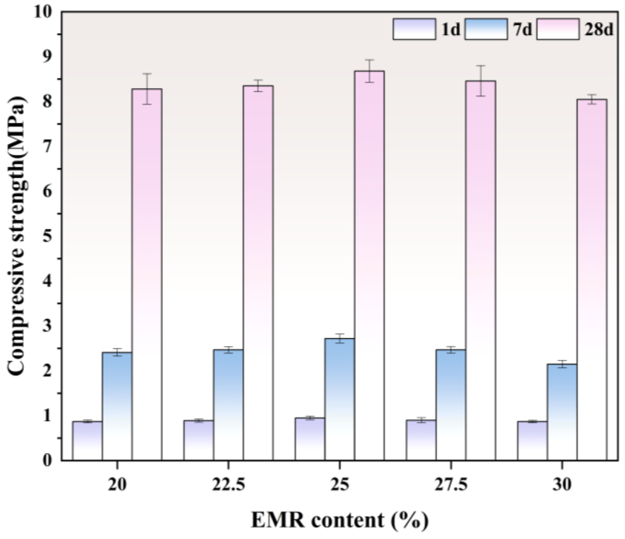
The variation in compressive strength of EBFM at different curing ages with varying EMR content is illustrated in Figure 2. The compressive strength of EBFM increases first and then decreases as EMR content increases, reaching a maximum in group A3. Specifically, the 1 d, 7 d and 28 d compressive strengths of group A3 are 0.95 MPa, 2.72 MPa, and 8.68 MPa, respectively.
There is an amount of gypsum in EMR, which can promote hydration reactions when present in moderate quantities. In the highly alkaline environment provided by quicklime, it reacts with silico-aluminate phases in the system to form hydration products. These fill internal pores and densify the microstructure, thereby enhancing the compressive strength of EBFM. Moreover, the amount of hydration products is directly correlated with the compressive strength of the materials [37]. However, as the EMR content continues to increase, the proportion of inert components that do not participate in hydration reactions also increases. It is accompanied by a decrease in the content of fly ash, which contains pozzolanic active components. Consequently, the total amount of hydration products is reduced, leading to a decline in the compressive strength. In addition, excessive gypsum may result in the overproduction of expansive ettringite, causing structural damage and the formation of microcracks, which further deteriorate the strength of EBFM.
Although the early-age compressive strength of the backfill material is relatively low, it still meets the engineering requirements. As the curing age increases, there is sufficient time to make hydration reactions proceed more fully, resulting in an increased amount of hydration products. Consequently, the compressive strength of EBFM continues to increase, showing a particularly significant growth between 7 and 28 days. For example, in group A3, the compressive strength increased by 187.32% from 1 d to 7 d, and by 219.12% from 7 d to 28 d.

3.1.2. Fluidity and Bleeding Rate

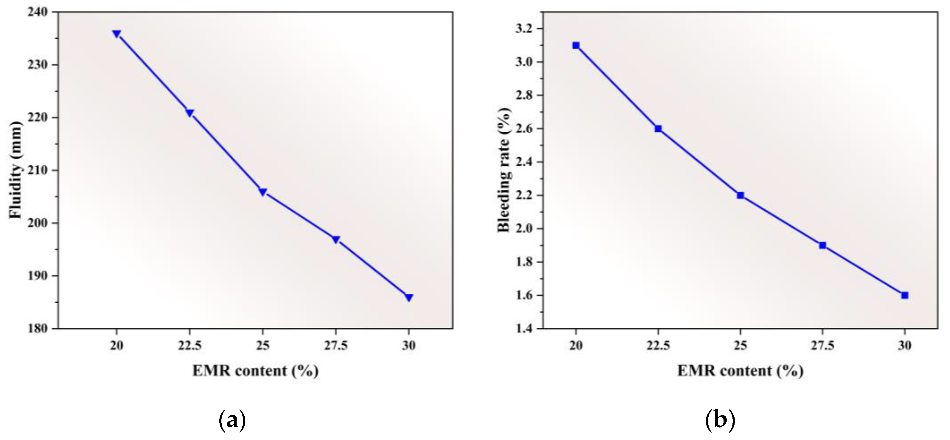
The effects of EMR content on the fluidity and bleeding rate of the filling materials are illustrated in Figure 3. As the EMR content increases, the fluidity of the slurry decreases. The fluidity of A1 reaches 234 mm, while that of group A5 drops to 196 mm. The trend can be attributed to the increasing content of hemihydrate gypsum in the mixture, which consumes a significant amount of free water when it transforms to dihydrate gypsum, thereby reducing the fluidity of the slurry [38,39].
In addition, the rough surface of EMR particles leads to a larger specific surface area. As the EMR content increases, more free water is required to wet the particle surfaces, resulting in greater water absorption and reduced slurry fluidity. In contrast, fly ash particles are smooth and spherical, requiring less water to reach a wetted state. Moreover, fly ash promotes rolling rather than sliding among particles in the slurry, acting as a “ball-bearing” lubricant. However, as the EMR content increases, the content of fly ash correspondingly decreases, weakening the lubricating effect and further reducing fluidity.
Filling materials are required to meet the requirements for bleeding rate. A controlled bleeding rate is beneficial for filling material pumping, as it helps reduce the friction between the slurry and the pipeline wall, thus enhancing transport efficiency [40]. Figure 4 shows the effect of EMR content on the bleeding rate. The bleeding rate exhibits a decreasing trend with increasing EMR content. When the EMR content is 20 wt.%, the bleeding rate reaches a maximum of 3.1%, and it decreases to 1.6% as the EMR content increases to 30 wt.%. The reduction is primarily due to the increased content of CaSO4·0.5H2O in the system with higher EMR content, which absorbs free water in the slurry and hydrates into gypsum (CaSO4·2H2O), thereby reducing the amount of free water and leading to a lower bleeding rate in the filling material. This phenomenon is consistent with findings reported in previous studies [41,42].

3.1.3. Setting Time

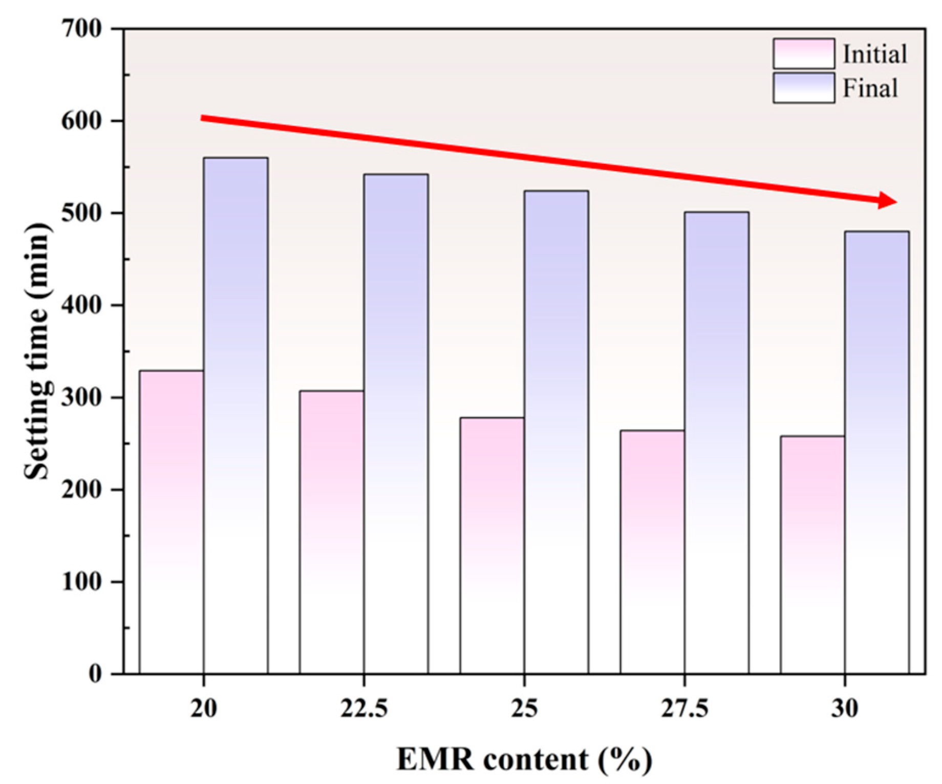
The effect of EMR content on the setting time of EBFM is shown in Figure 4. As EMR content increases, a shorter setting time is observed. Specifically, the initial and final setting times of group A1 are 329 min and 560 min, respectively, while those of group A4 are 264 min and 501 min.
The shortened setting time with increasing EMR content is primarily attributed to the higher amount of hemihydrate gypsum in the system, which consumes free water in the slurry and transfers into dihydrate gypsum, which absorbs additional free water and thus accelerates the setting process [43]. In addition, the sulfates contained in EMR, as an activator, promote the dissolution of active aluminosilicate components in phosphorus slag and fly ash, thereby accelerating the hydration reactions and increasing the amount of hydration products, ultimately shortening the setting time of the filling material [44].

3.2. Sulfate Resistance

3.2.1. Porosity

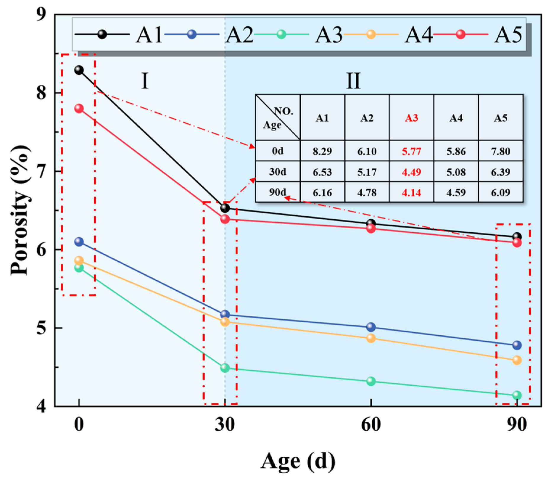
Porosity directly reflects the compactness of filling materials and serves as a key parameter for evaluating the resistance to sulfate attack [31]. In general, a higher porosity indicates a lower sulfate resistance, because more sulfate ions penetrate into the interior of the material. The effect of varying EMR content on porosity at varying erosion ages is illustrated in Figure 5. After 28 days of standard curing, the A1 group exhibited the highest porosity at 8.29%, while the A3 group had the lowest porosity at only 5.77%. As sulfate erosion ages increase, all groups (A1–A5) showed a decreasing trend in porosity. It can be attributed to the ingress of sulfate ions into the pores, which promotes further hydration of unreacted components around the pore surfaces. The resulting hydration products gradually fill the pores, thereby reducing porosity and hindering further ingress of the sulfate ions, ultimately improving sulfate resistance of EBFM. With the increase in EMR content, the porosity of EBFM initially decreases and then increases. The trend is mainly due to the gypsum contained in EMR, which promotes the formation of hydration products that fill the pore spaces, leading to reduced porosity. However, when the EMR content increases continuously, there is an excessive amount of gypsum, which leads to the formation of expansive ettringite in greater quantities, resulting in the development of micro-expansion cracks within EBFM, thereby increasing porosity. As the sulfate erosion ages further increase, porosity tends to stabilize.

3.2.2. Mass Change

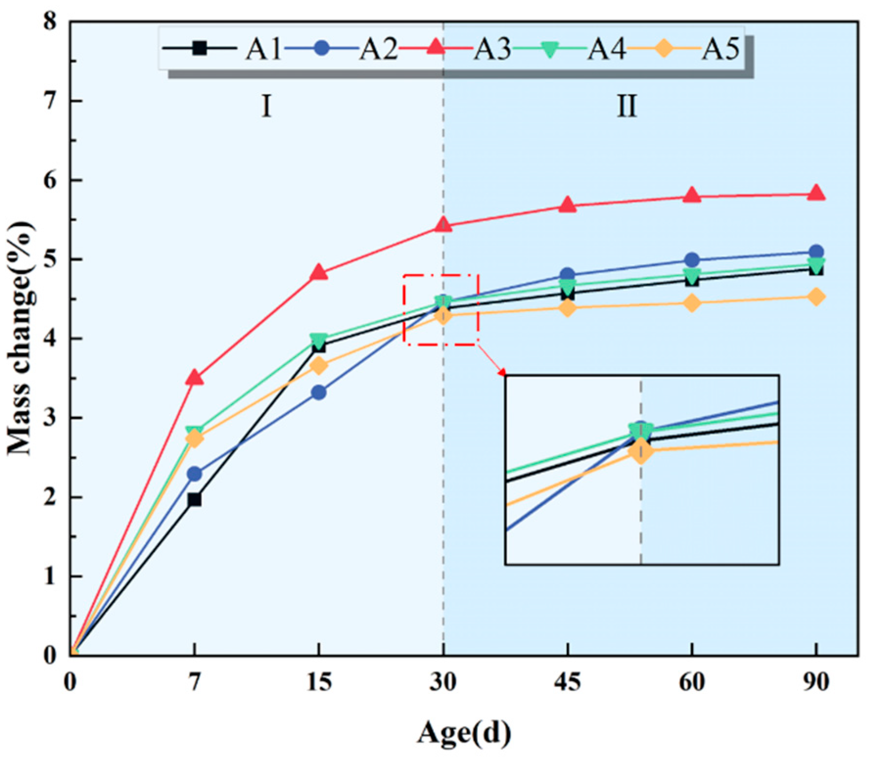
Figure 6 presents the effect of varying EMR content on mass change at varying erosion ages. As the erosion time increases, all specimens from groups exhibit a gradual increase in mass. Among them, the specimen with 25 wt.% EMR content shows the highest mass change rate, reaching 5.82% at 90 d. The mass increase is primarily attributed to the relatively high porosity of the specimen. During sulfate erosion, sulfate ions infiltrate the internal pores and react with residual particles around the pore, forming new hydration products that contribute to the observed mass increase [45]. The mass change process during sulfate erosion can be divided into two distinct stages: the rapid growth stage and the relatively stable stage. During the initial phase (0–30 d), the mass increases sharply, marking the rapid growth stage. After 30 days, the specimens enter a relatively stable stage, with a slower rate of mass change. In the first stage, sulfate ions from the Na2SO4 solution rapidly penetrate the internal pores, leading to the formation of substantial amounts of hydration products and resulting in a sharp increase in mass. In the second stage, the pores are largely filled by the new hydration products, leading to a denser internal structure. As a result, the pathways for sulfate ingress are gradually blocked, reducing the penetration of sulfate ions and the amount of further hydration products, which ultimately leads to the stabilization of mass changes. It is consistent with the discussion on porosity evolution presented in Section 3.2.1.

3.2.3. Corrosion Resistance Coefficient

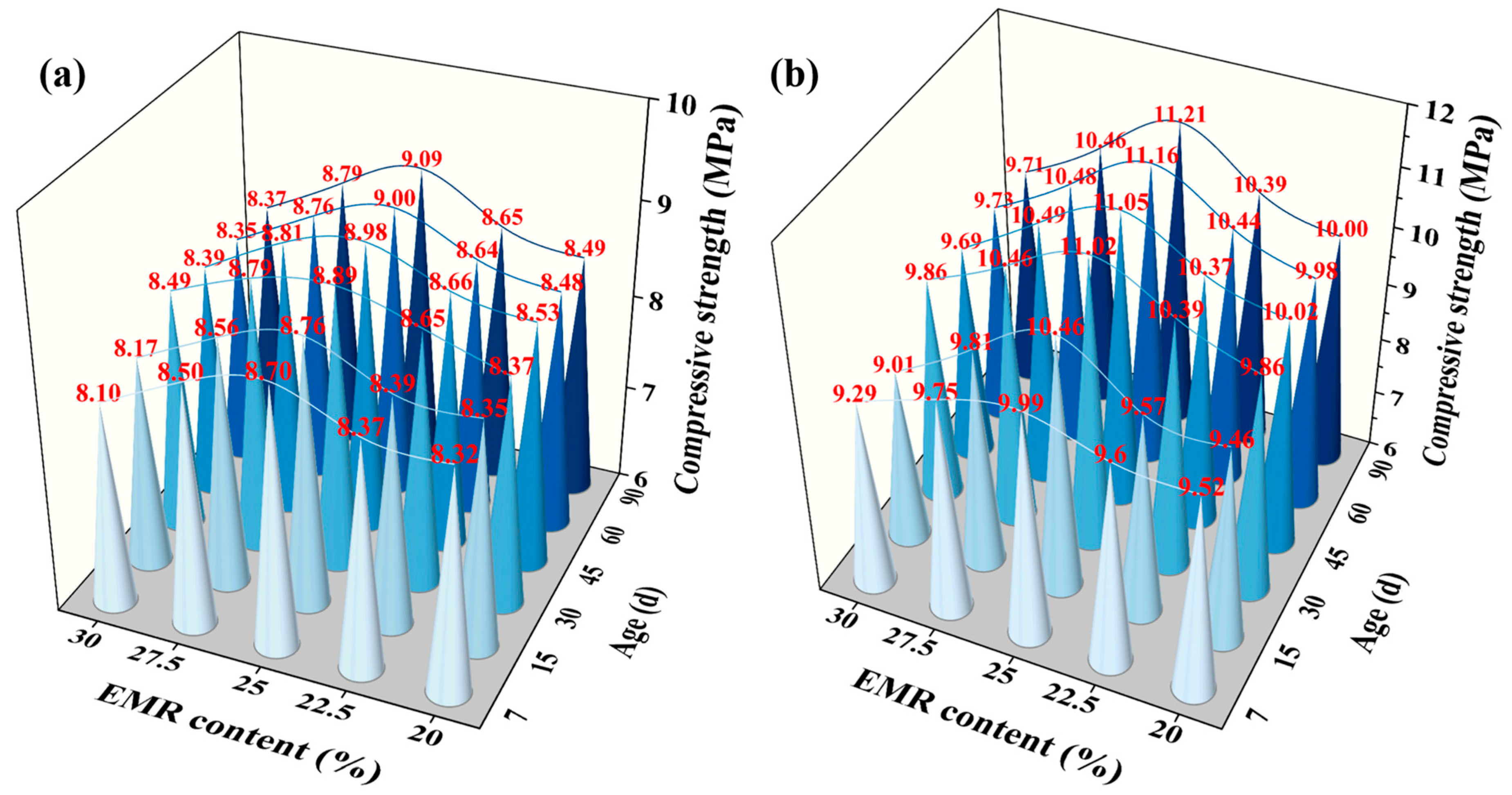
Figure 7 illustrates the effect of varying EMR content on compressive strength at varying erosion ages. As shown in Figure 7, the compressive strength of EBFM initially increases and then decreases with increasing EMR content, reaching a peak in group A3. It is consistent with the compressive strength development discussed in Section 3.1.1.
The compressive strength of backfill materials is required to reach 5 MPa. For cement-based filling materials, the compressive strength shows a decrease after sulfate attack, with a CRC less than 1.0. In contrast, the EBFM immersed in sodium sulfate solution did not exhibit a decline in compressive strength; instead, a noticeable enhancement was observed. The compressive strength of EBFM tends to increase with increasing erosion age. Taking group A3 as an example, the compressive strengths of the specimens after 7, 15, 30, 45, 60, and 90 days of sulfate erosion are 9.99 MPa, 10.06 MPa, 11.02 MPa, 11.05 MPa, 11.16 MPa, and 11.21 MPa, more than the standard value. During the 90-day erosion period, the compressive strength continuously increases, with a particularly rapid growth observed in the first 30 days. The sustained increase in compressive strength over the 90-day erosion period suggests that the filling material continues to undergo hydration under sulfate attack. The formation of ettringite (AFt) and amorphous C–S–(A)–H gel products fills the internal pores and interlocks to form a denser microstructure. It enhances the overall structural integrity and ensures the long-term stability of the EBFM’s performance in sulfate environments.
In contrast, the compressive strength of N group is slightly affected by the immersion duration, showing minimal variation over time. For Group A3, the compressive strengths after 7, 15, 30, 45, 60, and 90 days are 8.70 MPa, 8.76 MPa, 8.89 MPa, 8.98 MPa, 9.00 MPa, and 9.09 MPa, respectively, indicating relatively stable performance.
More importantly, the comparison of the compressive strengths in N and E groups reveals that specimens immersed in the sulfate solution exhibit significantly higher strength. It is primarily attributed to the presence of sulfate ions, which penetrate the specimens through surface pores and microcracks, promoting continued hydration of residual particles. The newly formed hydration products fill voids and cracks, leading to a denser internal microstructure and an associated increase in compressive strength. In contrast, N group lacks the sulfate ions necessary to stimulate further hydration; thus, the slight strength increase observed in this group is mainly due to the ongoing process of the initial hydration reaction.
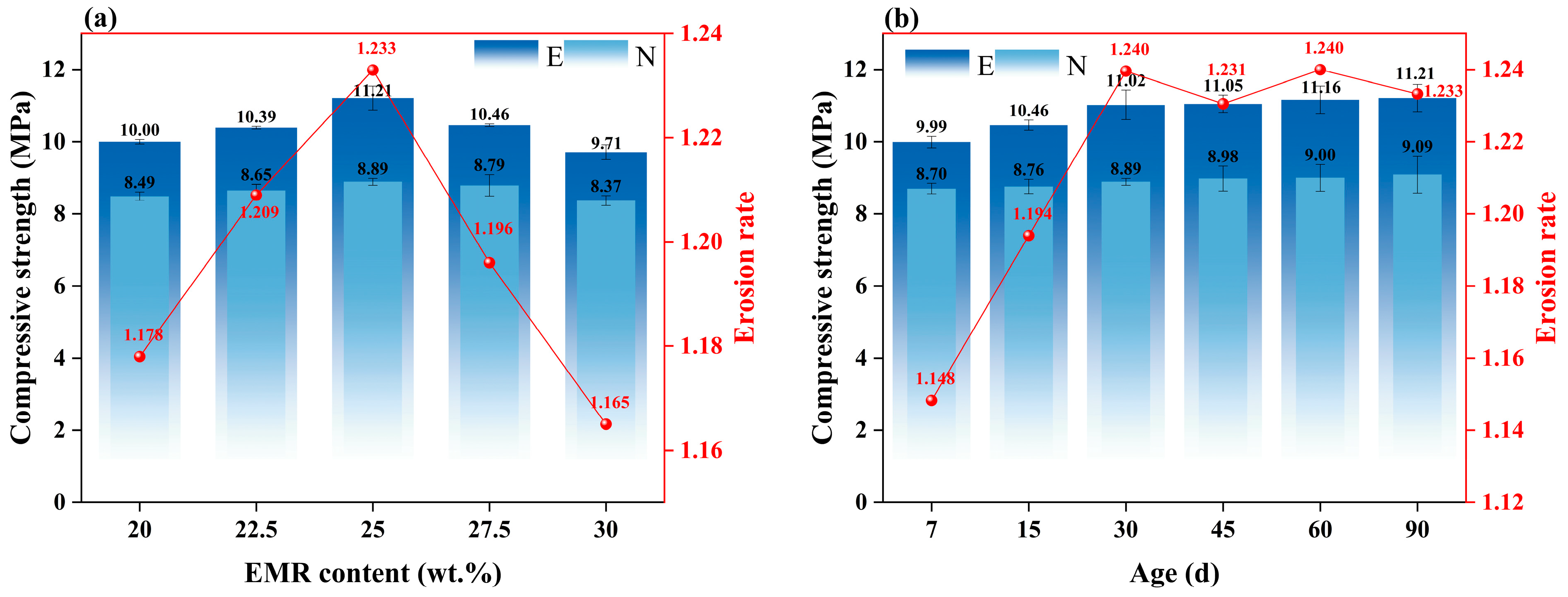
The corrosion resistance coefficient (CRC) serves as a critical parameter for assessing the sulfate resistance performance of filling materials, and it is strongly correlated with compressive strength. As shown in Figure 8a, the CRC exhibits a trend of initial increase followed by a stabilization with the increasing content of EMR. When its content is low, the filling material presents a relatively lower compressive strength and higher porosity, resulting in poorer sulfate resistance and consequently a lower CRC. As outlined in Section 3.2.1, increasing the EMR content initially decreases the porosity of the EBFM, followed by a slight increase at higher content levels. The lowest porosity is observed in Group A3, which also exhibits the highest corrosion resistance coefficient (CRC) among all groups.
As shown in Figure 8b, the CRC demonstrates a rapid increase firstly, followed by a plateau as erosion age increases. Within the first 30 days, the CRC increases sharply from 1.148 to 1.240. It is mainly attributed to the ongoing hydration reactions under the sulfate-rich environment, which improve the EBFM’s density and compressive strength. After 30 days, as the concentration of sulfate ions in the solution declines and the internal pores and microcracks are gradually filled by hydration products, the pathways for ion ingress become blocked. Consequently, the rate of further hydration slows, leading to a stagnation of strength development [46], and the CRC gradually stabilizes within the range of 1.23 to 1.24.

3.3. Microscope Analysis

3.3.1. XRD

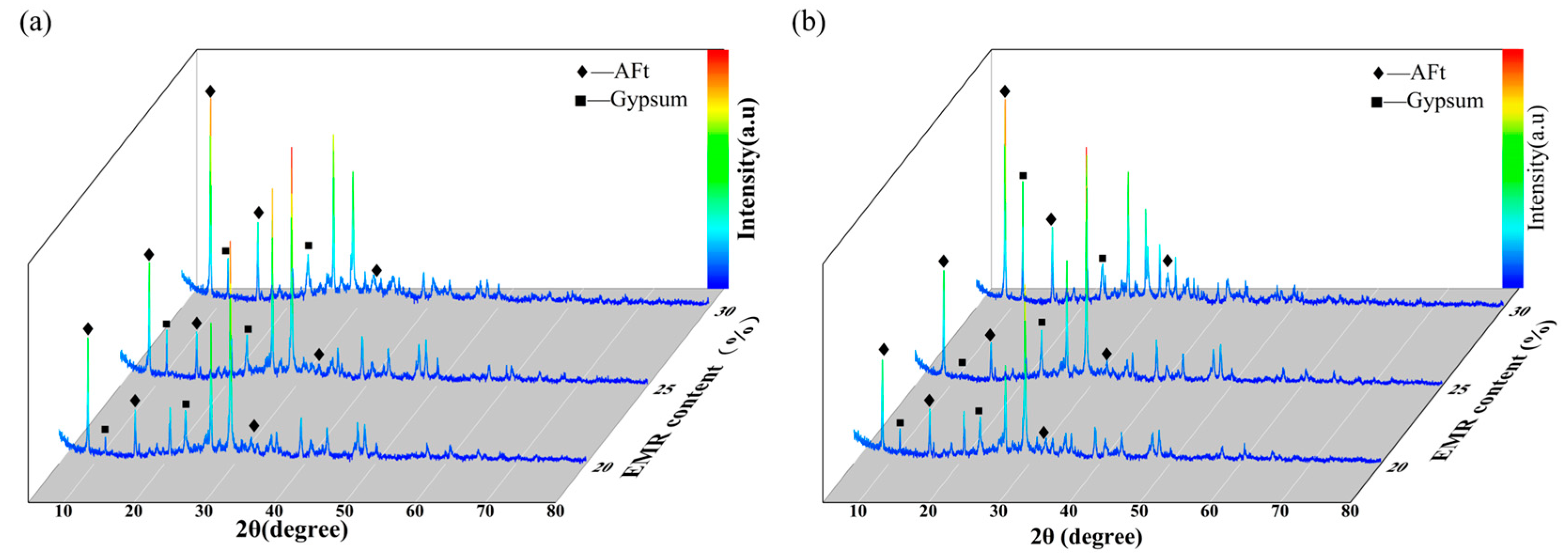
In this section, specimens with EMR contents of 20 wt.% (A1), 25 wt.% (A3), and 30 wt.% (A5) were subjected to XRD analysis after 15 days of exposure to either deionized water (N) or sodium sulfate solution (E). Figure 9 presents the XRD patterns of EBFM with varying EMR contents after 15 days of erosion.
As shown in Figure 9a, the intensity of the gypsum diffraction peak at approximately 12° increases with the increasing EMR content. It is attributed to the fact that gypsum is one of the main components of EMR, and the content correspondingly increases as the EMR content rises. Similarly, the diffraction peaks corresponding to ettringite at around 8°, 16°, and 32° exhibit the same trend, reaching maximum intensity in group A5. In the EBFM, gypsum serves as the primary source of sulfate ions required for ettringite formation. Therefore, under the condition of sufficient aluminum content, the amount of ettringite formed in the N group is directly determined by the gypsum content in the mixture. It explains the consistent variation observed in the diffraction peak intensities of both gypsum and ettringite.
After penetrating the interior of the material, sulfate ions typically undergo a sequence of reactions as follows: (a) initially adsorbed by calcium silicate hydrate (C–S–H) gel; (b) reacts with calcium hydroxide to form gypsum; and (c) subsequent formation of ettringite through reaction with aluminate phases in an alkaline environment [47]. By comparing Figure 9a,b, it is observed that the gypsum and ettringite peaks of A1E are higher than A1N. The gypsum peak near 12° in the A5E group shows a pronounced increase relative to the A5N group, while the intensity of the ettringite peaks remains largely unchanged, which indicates that sulfate attack leads to substantial gypsum formation.
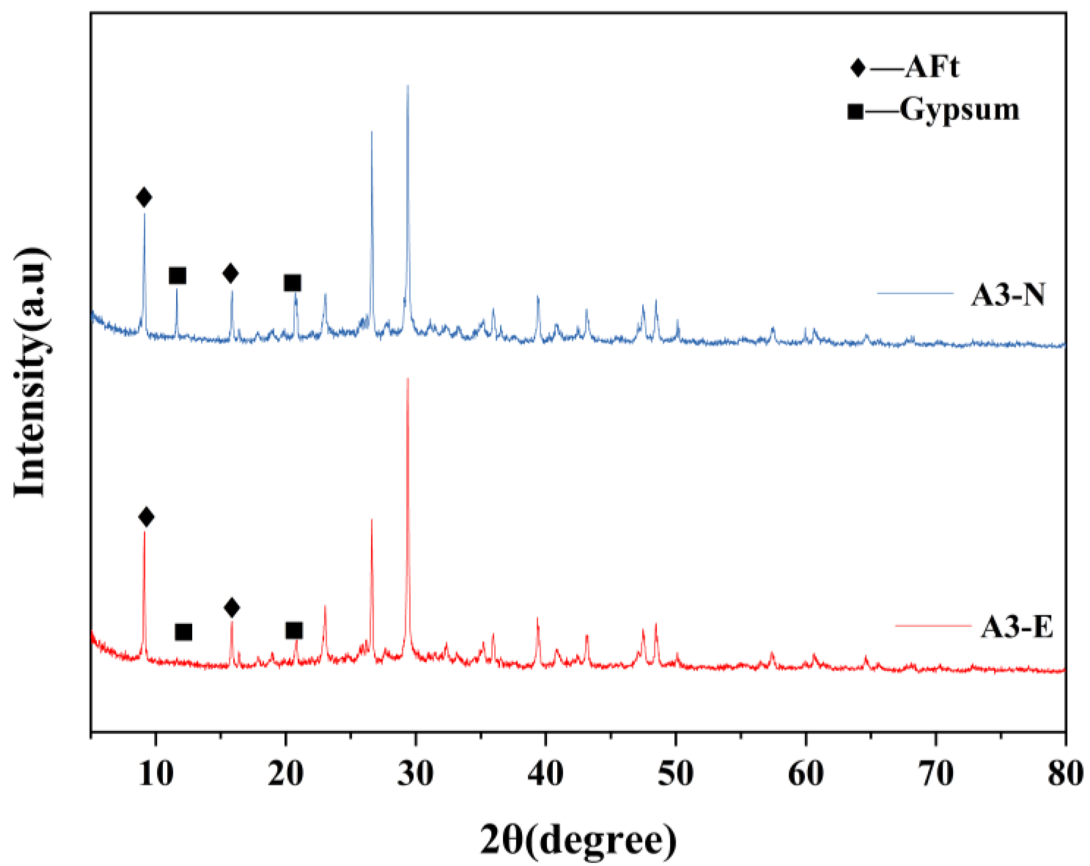
In contrast, it reveals that the gypsum diffraction peak of the A3E group near 12° disappears in Figure 10, while the ettringite peak shows a slight increase in intensity. It suggests that the gypsum participates in the formation of ettringite content, resulting in the gypsum diffraction peak disappearing. The observed differences in the diffraction peak evolution are primarily attributed to variations in the amount of hydration products generated, which are influenced by the differing EMR contents.
In Group A1E, sulfate ions are adsorbed by the C–S–H gel initially and then react with the residual calcium hydroxide to form gypsum and promote the formation of ettringite. As the content of EMR increases, the fly ash content decreases, leading to a reduction in the amount of active components in the system as well as a decrease in calcium hydroxide participating in the hydration reaction. Consequently, the residual calcium hydroxide in the system increases. For Group A5E specimens, the lower fly ash content results in fewer active components, producing less C–S–H gel, and leaving a large amount of residual calcium hydroxide. Therefore, the amount of sulfate ions adsorbed by the C–S–H gel after sulfate erosion is relatively small. The continuous ingress of sulfate ions primarily reacts with the abundant calcium hydroxide to generate a substantial amount of gypsum.
Specimens from Group A3 generate a larger amount of C–S–H gel, which absorbs most sulfate ions during sulfate attack. A small fraction of the sulfate ions promotes the dissolution of active components in the residual fly ash, which facilitates the consumption of gypsum and formation of ettringite. The process is reflected in the attenuation of the gypsum diffraction peak and a slight increase in the ettringite peak intensity.
Gypsum significantly influences the EBFM properties, excessive gypsum content within the EBFM can degrade mechanical strength and reduce durability [48]. The observed reduction in gypsum peaks in Group A3 after sulfate erosion is beneficial to the durability. It is consistent with the conclusion drawn in Section 3.2.3, where Group A3 specimens exhibited the highest compressive strength.

3.3.2. SEM

Figure 11 presents the SEM micrographs of specimens from groups A1N, A3N, and A5N at 15 d. In Groups A1N and A5N, numerous cracks and pores are clearly visible, indicating a loosely bonded microstructure. The porous morphology results in a less compacted EBFM, which is directly associated with inferior mechanical properties.
In contrast, the microstructure of Group A3N appears significantly denser, with fewer observable pores and microcracks. It suggests that the EBFM incorporating 25% EMR exhibits a more compact internal structure, lower porosity, and consequently enhanced mechanical performance. These findings align well with the earlier conclusion in this study that Group A3 achieved the highest compressive strength among all groups.
In Figure 12a, the SEM micrographs of Group A3N reveals the presence of ettringite crystals within the internal pores of the material. However, these ettringite crystals are interlocked loosely and predominantly exhibit a fine needle-like morphology. In contrast, the A3E specimen subjected to sulfate erosion shows a notable increase in ettringite and other hydration products. Sulfate ions penetrate the materials through pores and microcracks, reacting with residual active components in the matrix to promote further hydration. The abundant formation of ettringite within the pores and cracks does not cause strength degradation; rather, due to its expansive properties, it fills these voids, which results in a denser microstructure and consequently enhanced compressive strength after sulfate attack.
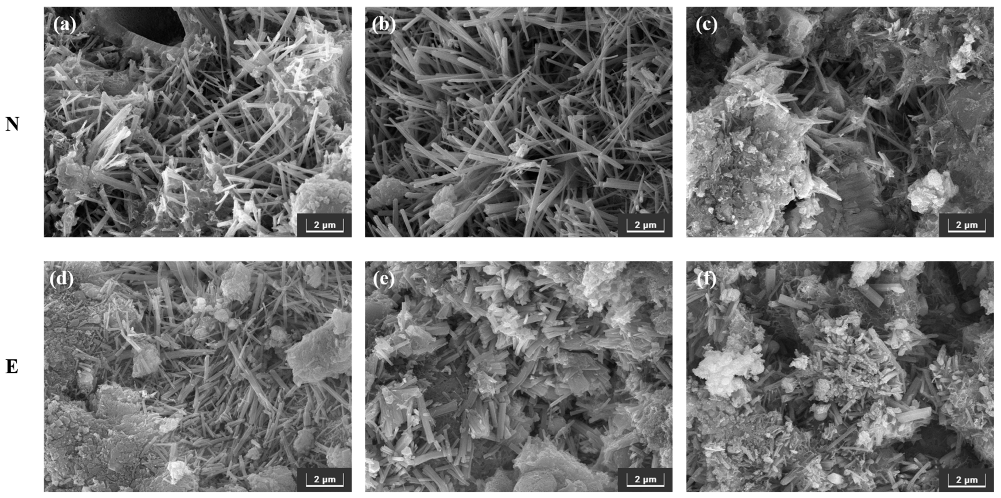
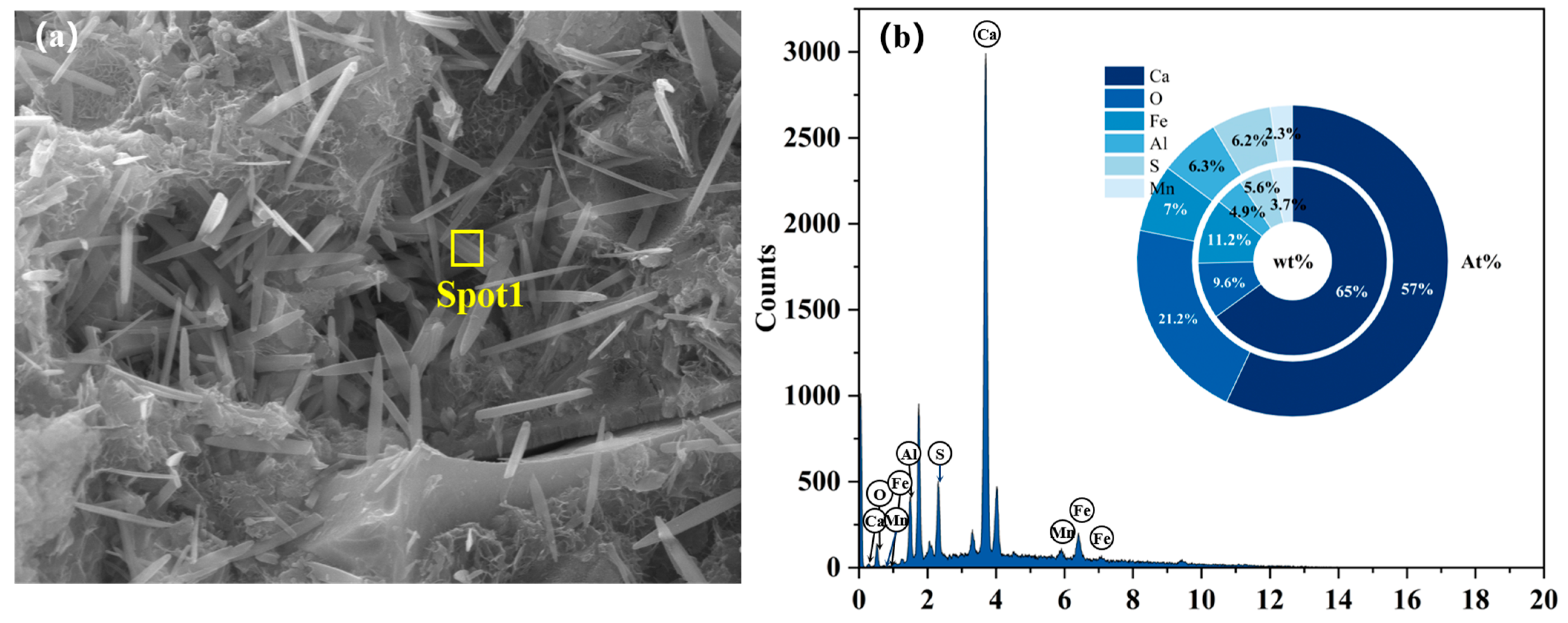
Figure 13 presents SEM micrographs of Group A1E, A3E, and A5E at 90 d. In Figure 13a–c, it can be observed that the ettringite crystal is mostly needle-like. The EDS results are shown in Figure 14. It can be seen that there is ferrite present in the needle-like ettringite. This is because the addition of TIPA could complex Fe3+, which promotes the dissolution of ferrous component in EMR and FA. As depicted in Figure 14b, the ettringite exhibits an Fe content of 7.0 At.% alongside an Al content of 6.3 At.%, yielding an Fe/Al ratio of 1.11. The ferrous component participates in the hydration of ettringite and increases the surface energy of the ettringite (0 0 1) surface, indicating that the crystal of ettringite develops in this direction [49]. Although there are the differences in proportions, the specimens of group E exhibit a morphological transformation of ettringite from needle-like to columnar crystals, as shown in Figure 13d–f. The transformation reduces the gaps between adjacent ettringite crystals, which is beneficial for strength improvement. The mechanism underlying the transformation is that sulfate ions are adsorbed onto the flanks of ettringite crystals, which has a larger surface area. Further, they continue participating in the hydration reactions, leading to continuous lateral growth that envelops the needle-like crystals and results in thicker columnar ettringite formation [50].
As observed in Figure 15a, there are gel-like substances formed on the surface of FA particles, indicating that during the hydration of EBFM, the active components in FA and PS dissolve under the alkaline environment provided by quicklime and the sulfate ions from gypsum in EMR. In the pore and cracks, these dissolved species participate in hydration reactions to form hydration products, which tightly encapsulate FA, EMR, and PS particles. The hydration products consist of ettringite, C–S–H and C–A–S–H gels, with the gels densely surrounding the ettringite crystals, thereby restricting the expansion of ettringite. For A3 as an example, the fly ash microspheres in deionized water (N) remain intact, as marked in Figure 15a, while exposure to sodium sulfate solution (E) lead to the fracture of fly ash microspheres, as shown in Figure 15b,c. A small amount of hydration products form on the fractured surfaces, suggesting that sulfate ions penetrated the specimen, promoting the release of active components from FA particles and the subsequent formation of new hydration products, which were eventually encapsulated by C–S–H and AFt. It confirms that the hydration reaction of EBFM continues after sulfate attack, providing strong evidence for the observed increase in compressive strength and a corrosion resistance coefficient greater than 1.0 after sulfate erosion.

3.3.3. TG-DTG

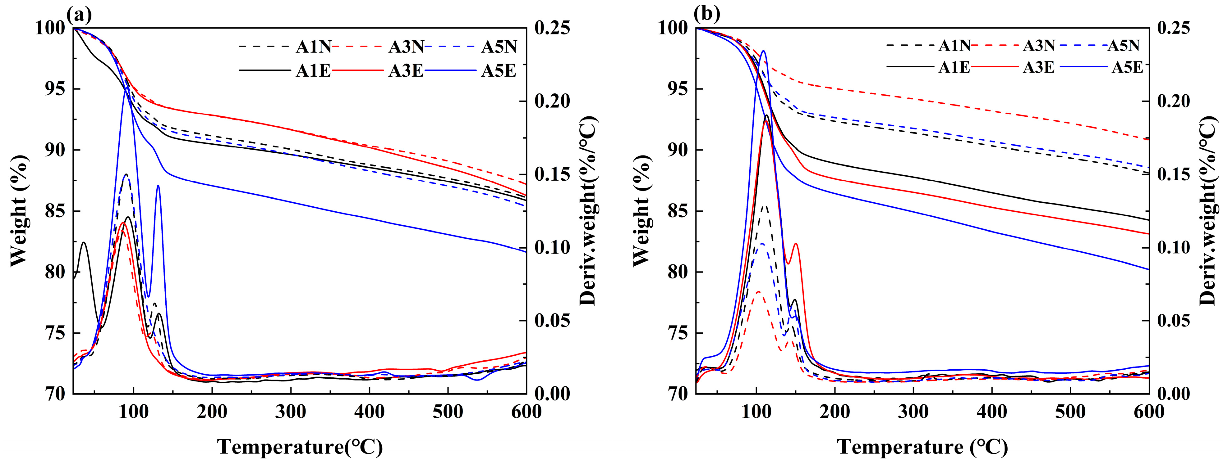
Figure 16 presents the TG-DTG curves of EBFM specimens immersed in different solutions for 15 and 30 days. As shown in Figure 16a,b, the TG curves demonstrate that when heated to 600 °C, Group E generally exhibits greater mass loss than Group N. It indicates an increased quantity of hydration products in the sulfate-attacked specimens. As the erosion age increases, the mass loss of samples progressively increases. For instance, Group A3E shows a decrease in residual mass from 86.24% at 15 days to 83.11% at 30 days, confirming that the formation of hydration products continues to rise from 15 days to 30 days.
As evidenced by the DTG curves in Figure 16a,b, the endothermic peak observed at approximately 100 °C corresponds to the dehydration of both C–S–H (C–A–H) gel and ettringite (AFt) [51]. The overlap of these decomposition peaks confirms the coexistence of AFt and C–(A)S–H gel phases in EBFM [52]. Notably, the intensity of endothermic peaks in Group E is stronger than Group N, which validates the enhanced formation of hydration products after sulfate attack.
The endothermic peak detected near 140 °C primarily results from the dehydration of CaSO4·2H2O to CaSO4·0.5H2O [53,54]. The significantly stronger peak intensity in Group E indicates greater gypsum formation in A1 and A5 mixtures under sulfate attack. The endothermic peak of A3E observed at approximately 140 °C disappears, indicating that gypsum in Group A3 has participated in the hydration reaction after sulfate attack. And there is no new gypsum formed during this process. As the erosion age extended to 30 days, the endothermic peaks at 100 °C and 140 °C in the A3E significantly increase in intensity, suggesting that the gel phase has reached saturation in terms of sulfate ion uptake. Subsequently, the sulfate ions react with calcium hydroxide present in the system, resulting in the formation of a large amount of gypsum. Additionally, residual active components in the material further reacted to form ettringite and C–(A)S–H gel.

3.4. Mechanism of Sulfate Resistance

The experimental results indicate that EBFMs exhibit excellent resistance to sulfate attack. The performance is primarily attributed to the formation of a dense microstructure, resulting from the interlocking of hydration products generated during the hydration process. Furthermore, residual components present in the EBFM can continue hydration to the generation of additional hydration products under sulfate attack, which contributes to increased material strength and enhanced compactness, thereby improving the sulfate resistance.
EMR contains both CaSO4·2H2O and CaSO4·0.5 H2O, along with a certain amount of silicon and aluminum components. In addition, FA and PS are rich in reactive silica-alumina species. Upon dissolution in water, quicklime (CaO) releases hydroxide ions, which provide a highly alkaline environment. Under alkaline conditions and further stimulation by sulfate ions released from EMR, fly ash and phosphorus slag are activated to release reactive AlO2 and SiO2 species. These react with the available calcium ions to form hydration products such as C–(A)S–H and AFt. Additionally, the ferrous components present in EMR and FA participate in the ettringite formation process, leading to the generation of Fe-Al ettringite. The corresponding reaction equations are shown in Equations (4)–(7).
C a 2 + + S i O 2 + O H + H 2 O C S H
C a 2 + + S i O 2 + A l O 2 + O H + H 2 O C A S H
C a 2 + + A l 3 + + O H + S O 4 2 + H 2 O C a 6 A l 2 ( S O 4 ) 3 ( O H ) 12 · 26 H 2 O
C a 2 + + F e 3 + + A l 3 + + O H + S O 4 2 + H 2 O C a 6 ( A l x F e 1 x ) 2 ( S O 4 ) 3 ( O H ) 12 · 26 H 2 O
The schematic diagram of the sulfate resistance mechanism in EBFM is shown in Figure 17. When EBFMs are exposed to a sulfate-rich environment, sulfate ions gradually penetrate from the surface pores into the interior of the material, leading to an increased concentration of sulfate ions within the pore structure. Initially, these sulfate ions are absorbed by calcium silicate hydrate (C–S–H) gel. As the concentration continues to rise with in materials, the excess sulfate ions react with the remaining calcium hydroxide to form gypsum. Subsequently, the newly formed gypsum particles further react with residual reactive components such as fly ash, phosphorus slag and unreacted EMR particles, generating additional hydration products including ettringite (AFt) and gel-like substances. The hydration products interlock and bridge across microcracks and pores. The ettringite crystals, initially in needle-like form, transform into short columnar structures, resulting in the spacing between adjacent ettringite crystals decreasing. Simultaneously, the newly formed gel phase encapsulates the ettringite crystals, constraining their expansion. The gel and ettringite effectively fill internal pores and cracks, reducing the overall porosity of the materials. Additionally, the hydration product Al-AFt tends to transform into AFm phase in conventional cementitious materials [55]. The AFm phase subsequently reacts with sulfate ions to form secondary ettringite, which contributes the fundamental reason for poor sulfate resistance [56,57]. However, the abundant calcium sulfate in EMR and ferrous component components in EMR and FA promote the formation of Fe-AFt [58]. It demonstrates superior stability, which could not transform into AFm phase, representing a key mechanism for the better sulfate resistance [59]. As demonstrated by the above, the internal microstructure of the EBFM becomes denser and remains stable, thereby exhibiting excellent resistance to sulfate attack [60].

4. Conclusions

In this study, the effects of different contents of EMR on the basic performance and sulfate resistance of EBFM were investigated. Additionally, the mechanism of sulfate resistance in EBFM was elucidated. Notably, EBFM demonstrated the ability to transform the presence of sulfate ions in mine water (a typically adverse condition) into a beneficial factor that enhances material performance. The main conclusions are as follows:
(1)
The mechanical performance of EBFM is optimal when the EMR content is 25 wt.%. The highest compressive strength of 8.68 MPa at 28 d is achieved at a 25 wt.% EMR content. Moreover, an increase in EMR content leads to a decrease in fluidity and bleeding rate of the slurry, and the setting time is progressively shortened.
(2)
The EBFM exhibits excellent sulfate resistance. It contributes to compressive strength enhancement, porosity reduction, and mass increase of EBFM in a sulfate environment. The compressive strength of EBFM in sulfate solution is significantly higher than that of those cured in deionized water, while the porosity is notably reduced. Corrosion resistance coefficients of all groups exceed 1.0. In the same erosion age, the A3 group with a 25 wt.% EMR content has the highest corrosion resistance coefficient. After 30 days of erosion, the corrosion resistance coefficient stabilized between 1.23 and 1.24.
(3)
After sulfate erosion, there are more hydration products generated in the EBFM, which makes microstructure denser. In sulfate-rich environments, sulfate ions penetrated the interior of the material through pore channels, promoting the dissolution of residual particles. These active components further participate in the hydration to generate additional hydration products such as C–(A)S–H and AFt. The morphology of ettringite crystals transforms from needle-like to columnar structure, while the gels encapsulate the ettringite crystals, effectively inhibiting the expansion of Al-AFt. In addition, the Fe-AFt formed during hydration demonstrates superior stability. These hydration products fill the internal pores and cracks, interlocking within the matrix, which results in a denser microstructure and enhancement of mechanical strength.

Author Contributions

X.Z.: validation, project administration, funding acquisition. X.L. (Xin Liu): project administration, funding acquisition, supervision. Z.F.: data curation, writing—original draft preparation. S.Z.: validation, data curation, writing—original draft preparation, writing—review and editing, visualization. X.L. (Xiaoming Liu): Conceptualization, methodology, resources, supervision, writing—original draft preparation. All authors have read and agreed to the published version of the manuscript.

Funding

This research was funded by CEC Key Science and Technology Project “Research on the Preparation Key Technology of Phosphogypsum-based All-solid-waste Green Cement”, grant number: DJ-ZDXM-2023-25.

Data Availability Statement

The raw data supporting the conclusions of this article will be made available by the authors on request.

Acknowledgments

This study was mainly supported by Power Construction Corporation of China Guiyang Engineering Corporation Limited, Guiyang, China. The support from the Central South University is also appreciated.

Conflicts of Interest

Authors Zhang Xihe and Liu Xin were employed by the Power Construction Corporation of China Guiyang Engineering Corporation Limited. The authors declare that the research was conducted in the absence of any commercial or financial relationships that could be construed as a potential conflict of interest.

References

  1. Luan, H.J.; Jiang, Y.J.; Lin, H.L.; Wang, Y.H. A New Thin Seam Backfill Mining Technology and Its Application. Energies 2017, 10, 2023. [Google Scholar] [CrossRef]
  2. Zhu, W.B.; Xu, J.M.; Xu, J.L.; Chen, D.Y.; Shi, J.X. Pier-column backfill mining technology for controlling surface subsidence. Int. J. Rock Mech. Min. Sci. 2017, 96, 58–65. [Google Scholar] [CrossRef]
  3. Zhang, J.Q.; Yang, K.; He, X.; Zhao, X.Y.; Wei, Z.; He, S.X. Research status of comprehensive utilization of coal-based solid waste (CSW) and key technologies of filling mining in China: A review. Sci. Total Environ. 2024, 926, 171855. [Google Scholar] [CrossRef]
  4. Xue, G.L.; Yilmaz, E.; Wang, Y.D. Progress and prospects of mining with backfill in metal mines in China. Int. J. Miner. Metall. Mater. 2023, 30, 1455–1473. [Google Scholar] [CrossRef]
  5. Cao, H.; Gao, Q.; Zhang, X.Z.; Guo, B. Research Progress and Development Direction of Filling Cementing Materials for Filling Mining in Iron Mines of China. Gels 2022, 8, 192. [Google Scholar] [CrossRef] [PubMed]
  6. Deng, D.Q.; Cao, G.D.; Liang, Y.H. Experimental Study on Lead-Smelting Slag as Paste Filling Cementing Material. Geofluids 2022, 2022, 6126881. [Google Scholar] [CrossRef]
  7. Yang, L.; Hu, X.; Liu, Y.; Zhou, D.; Yuan, B.; Liu, S.; Luo, Z.; Li, X.; Jin, D.; Xu, F. Multiscale characterization of geopolymers modified with alkali-catalyzed nano-silica: Effects on dispersion and mechanical properties. Cem. Concr. Compos. 2026, 165, 106324. [Google Scholar] [CrossRef]
  8. Dan, H.C.; Ma, Z.M.; Li, M.J.; Ma, S.L.; Tan, J.W. Early performance and bonding mechanism of metakaolin (MK)- ground granulated blast furnace slag (GGBS) based geopolymer road repair mortar. Int. J. Pavement Eng. 2023, 24, 2252156. [Google Scholar] [CrossRef]
  9. Peng, Y.M.; Ma, K.L.; Long, G.C.; Xie, Y.J.; Yu, L.N.; Xie, Q.Q. Effect of Packing Density According to CPM on the Rheology of Cement-Fly Ash-Slag Paste. J. Mater. Civ. Eng. 2021, 33, 04021209. [Google Scholar] [CrossRef]
  10. Meng, W.Q.; Ma, K.L.; Long, G.C.; Meng, Q.Y.; Chen, R.J.; Fan, J.Z. Influence of Molybdenum Tailings Powder on the Hydration Characteristics of Cement Paste. J. Mater. Civ. Eng. 2024, 36, 04024115. [Google Scholar] [CrossRef]
  11. Ma, C.; Zhao, B.; He, Y.Z.; Li, F.; Long, G.C.; Du, Y.F. Preparation and properties of sustainable magnesium phosphate cement composites with recycled tire rubber particles. J. Clean. Prod. 2020, 262, 121253. [Google Scholar] [CrossRef]
  12. Chu, C.F.; Deng, Y.F.; Zhou, A.N.; Feng, Q.; Ye, H.; Zha, F.S. Backfilling performance of mixtures of dredged river sediment and iron tailing slag stabilized by calcium carbide slag in mine goaf. Constr. Build. Mater. 2018, 189, 849–856. [Google Scholar] [CrossRef]
  13. Wu, M.G.; Wang, C.; Zuo, Y.J.; Yang, S.; Zhang, J.Z.; Luo, Y. Study on strength prediction and strength change of Phosphogypsum-based composite cementitious backfill based on BP neural network. Mater. Today Commun. 2024, 41, 110331. [Google Scholar] [CrossRef]
  14. He, Y.; Chen, Q.S.; Qi, C.C.; Zhang, Q.L.; Xiao, C.C. Lithium slag and fly ash-based binder for cemented fine tailings backfill. J. Environ. Manag. 2019, 248, 109282. [Google Scholar] [CrossRef]
  15. Yin, L.L.; Guo, Q.; Wang, X.; Yuan, J.; Zhang, Q.F. Environmental filling materials based on phosphogypsum powder with municipal solid waste incineration ash. Sci. Rep. 2023, 13, 478. [Google Scholar] [CrossRef]
  16. Liu, X.M.; Liu, E. The Synergistic Mechanism and Stability Evaluation of Phosphogypsum and Recycled Fine Powder-Based Multi-Source Solid Waste Geopolymer. Polymers 2023, 15, 2696. [Google Scholar] [CrossRef]
  17. Liu, X.M.; Liu, E.R.; Fu, Y.T. Reduction in Drying Shrinkage and Efflorescence of Recycled Brick and Concrete Fine Powder-Slag-Based Geopolymer. Appl. Sci. 2023, 13, 2997. [Google Scholar] [CrossRef]
  18. Huang, H.; Li, X.R.; Shen, X.D. Hydration of ternary cement in the presence of triisopropanolamine. Constr. Build. Mater. 2016, 111, 513–521. [Google Scholar] [CrossRef]
  19. Wang, F.; Long, G.C.; Ma, K.L.; Zeng, X.H.; Tang, Z.; Dong, R.Z.; He, J.H.; Shangguan, M.H.; Hu, Q.C.; Liew, R.K.; et al. Recyling manganese-rich electrolytic residues: A review. Environ. Chem. Lett. 2023, 21, 2251–2284. [Google Scholar] [CrossRef]
  20. Bai, Y.Y.; Guo, W.C.; Wang, X.L.; Pan, H.M.; Zhao, Q.X.; Wang, D.L. Utilization of municipal solid waste incineration fly ash with red mud-carbide slag for eco-friendly geopolymer preparation. J. Clean. Prod. 2022, 340, 130820. [Google Scholar] [CrossRef]
  21. Luo, W.J.; Li, B.; Yang, G.; Xu, M.X.; Pang, C.H.; Kow, K.W.; Wu, T. Utilisation of electrolytic manganese residue as a sulphate activator in producing concrete blocks with high-volume fly ash. J. Clean. Prod. 2024, 434, 139813. [Google Scholar] [CrossRef]
  22. He, S.C.; Jiang, D.Y.; Hong, M.H.; Liu, Z.H. Hazard-free treatment and resource utilisation of electrolytic manganese residue: A review. J. Clean. Prod. 2021, 306, 127224. [Google Scholar] [CrossRef]
  23. Wang, D.Q.; Wang, Q.; Xue, J.F. Reuse of hazardous electrolytic manganese residue: Detailed leaching characterization and novel application as a cementitious material. Resour. Conserv. Recycl. 2020, 154, 104645. [Google Scholar] [CrossRef]
  24. Li, W.L.; Jin, H.X.; Xie, H.Y.; Wang, D.L. Progress in comprehensive utilization of electrolytic manganese residue: A review. Environ. Sci. Pollut. Res. 2023, 30, 48837–48853. [Google Scholar] [CrossRef]
  25. Wang, G.J.; Sun, Q.; Qi, C.X.; Liu, L.; Tan, Y.; Su, L.J. Mechanical properties and microscopic characterization of cemented paste backfill with electrolytic manganese residue matrix binder. J. Mater. Res. Technol. 2023, 23, 2075–2088. [Google Scholar] [CrossRef]
  26. Lan, J.R.; Sun, Y.; Tian, H.; Zhan, W.; Du, Y.G.; Ye, H.P.; Du, D.Y.; Zhang, T.C.; Hou, H.B. Electrolytic manganese residue-based cement for manganese ore pit backfilling: Performance and mechanism. J. Hazard. Mater. 2021, 411, 124941. [Google Scholar] [CrossRef] [PubMed]
  27. Zhang, Y.L.; Liu, X.M.; Xu, Y.T.; Tang, B.W.; Wang, Y.G. Preparation of road base material by utilizing electrolytic manganese residue based on Si-Al structure: Mechanical properties and Mn2+ stabilization/solidification characterization. J. Hazard. Mater. 2020, 390, 122188. [Google Scholar] [CrossRef] [PubMed]
  28. Li, W.C.; Fall, M. Sulphate effect on the early age strength and self-desiccation of cemented paste backfill. Constr. Build. Mater. 2016, 106, 296–304. [Google Scholar] [CrossRef]
  29. Bondar, D.; Nanukuttan, S. External Sulphate Attack on Alkali-Activated Slag and Slag/Fly Ash Concrete. Buildings 2022, 12, 94. [Google Scholar] [CrossRef]
  30. Aydin, S.; Baradan, B. Sulfate resistance of alkali-activated slag and Portland cement based reactive powder concrete. J. Build. Eng. 2021, 43, 103205. [Google Scholar] [CrossRef]
  31. Komljenovic, M.; Bascarevic, Z.; Marjanovic, N.; Nikolic, V. External sulfate attack on alkali-activated slag. Constr. Build. Mater. 2013, 49, 31–39. [Google Scholar] [CrossRef]
  32. GB/T 8077-2023; Test Methods for the Homogeneity of Concrete Admixtures. Standardization Administration of the People’s Republic of China: Beijing, China, 2023.
  33. GB/T 1346-2024; Test Method for Standard Consistency, Setting Time, and Stability of Cement. Standardization Administration of the People’s Republic of China: Beijing, China, 2024.
  34. JTG E30-2005; Testing Methods of Cement and Concrete for Highway Engineering. Ministry of Transport of the People’s Republic of China: Wuhan, China, 2005.
  35. GB/T 50082-2009; Standard for Test Methods of Long-Term Performance and Durability of Ordinary Concrete. Standardization Administration of the People’s Republic of China: Beijing, China, 2009.
  36. Tang, D.S.; Yang, C.H.; Li, X.Y.; Zhu, X.H.; Yang, K.; Yu, L.W. Mitigation of efflorescence of alkali-activated slag mortars by incorporating calcium hydroxide. Constr. Build. Mater. 2021, 298, 123873. [Google Scholar] [CrossRef]
  37. Qin, X.T.; Cao, Y.H.; Guan, H.W.; Hu, Q.S.; Liu, Z.H.; Xu, J.; Hu, B.; Zhang, Z.Y.; Luo, R. Resource utilization and development of phosphogypsum-based materials in civil engineering. J. Clean. Prod. 2023, 387, 135858. [Google Scholar] [CrossRef]
  38. Xu, Y.T.; Liu, X.M.; Zhang, Y.L.; Tang, B.W.; Mukiza, E. Investigation on sulfate activation of electrolytic manganese residue on early activity of blast furnace slag in cement-based cementitious material. Constr. Build. Mater. 2019, 229, 116831. [Google Scholar] [CrossRef]
  39. Wu, Z.H.; Zhang, H.; Pu, S.Y.; Cai, G.J.; Duan, W.; Song, H.L.; Zeng, C.; Yang, Y.H. Synergistic preparation of geopolymer using electrolytic manganese residue, coal slag and granulated blast furnace slag. J. Build. Eng. 2024, 91, 109609. [Google Scholar] [CrossRef]
  40. Zhou, N.; Zhang, J.X.; Ouyang, S.Y.; Deng, X.J.; Dong, C.W.; Du, E.B. Feasibility study and performance optimization of sand-based cemented paste backfill materials. J. Clean. Prod. 2020, 259, 120798. [Google Scholar] [CrossRef]
  41. Liu, C.B.; Gao, J.M.; Tang, Y.B.; Zhao, Y.S. Early hydration and microstructure of gypsum plaster revealed by environment scanning electron microscope. Mater. Lett. 2019, 234, 49–52. [Google Scholar] [CrossRef]
  42. Yin, S.S.; Yang, L.C. α or β?-hemihydrates transformed from dihydrate calcium sulfate in a salt-mediated glycerol-water solution. J. Cryst. Growth 2020, 550, 125885. [Google Scholar] [CrossRef]
  43. Wang, F.; Long, G.C.; Bai, M.; Wang, J.L.; Zhou, J.L.; Zhou, X. Application of electrolytic manganese residues in cement products through pozzolanic activity motivation and calcination. J. Clean. Prod. 2022, 338, 130629. [Google Scholar] [CrossRef]
  44. Piatak, N.M.; Parsons, M.B.; Seal, R.R. Characteristics and environmental aspects of slag: A review. Appl. Geochem. 2015, 57, 236–266. [Google Scholar] [CrossRef]
  45. Lv, Q.F.; Wang, Z.S.; Gu, L.Y.; Chen, Y.; Shan, X.K. Effect of sodium sulfate on strength and microstructure of alkali-activated fly ash based geopolymer. J. Cent. South Univ. 2020, 27, 1691–1702. [Google Scholar] [CrossRef]
  46. Chen, F.; Gao, J.M.; Qi, B.; Shen, D.M. Deterioration mechanism of plain and blended cement mortars partially exposed to sulfate attack. Constr. Build. Mater. 2017, 154, 849–856. [Google Scholar] [CrossRef]
  47. Fall, M.; Pokharel, M. Coupled effects of sulphate and temperature on the strength development of cemented tailings backfills: Portland cement-paste backfill. Cem. Concr. Compos. 2010, 32, 819–828. [Google Scholar] [CrossRef]
  48. Zhao, B.; Wang, G.J.; Zhao, K.; Wang, M.L.; Wu, B.S.; Li, S.J.; Chen, Q.L.; Geng, J.B. Mechanical properties, permeability and microstructure of steam-cured fly ash mortar mixed with phosphogypsum. Constr. Build. Mater. 2023, 400, 132582. [Google Scholar] [CrossRef]
  49. Wan, D.W.; Zhang, W.Q.; Tao, Y.; Wan, Z.H.; Wang, F.Z.; Hu, S.G.; He, Y.J. The impact of Fe dosage on the ettringite formation during high ferrite cement hydration. J. Am. Ceram. Soc. 2021, 104, 3652–3664. [Google Scholar] [CrossRef]
  50. Sha, S.N.; Ma, Y.H.; Lei, L.; Zhang, Y.R.; Liu, Y.; Xiao, Y.C.; Shi, C.J. Effect of polycarboxylate superplasticizers on the growth of ettringite in deionized water and synthetic cement pore solution. Constr. Build. Mater. 2022, 341, 127602. [Google Scholar] [CrossRef]
  51. Gijbels, K.; Nguyen, H.; Kinnunen, P.; Schroeyers, W.; Pontikes, Y.; Schreurs, S.; Illikainen, M. Feasibility of incorporating phosphogypsum in ettringite-based binder from ladle slag. J. Clean. Prod. 2019, 237, 117793. [Google Scholar] [CrossRef]
  52. Meskini, S.; Samdi, A.; Ejjaouani, H.; Remmal, T. Valorization of phosphogypsum as a road material: Stabilizing effect of fly ash and lime additives on strength and durability. J. Clean. Prod. 2021, 323, 129161. [Google Scholar] [CrossRef]
  53. Huang, X.Q.; Jiang, M.M.; Zhao, X.R.; Tang, C.L. Mechanical properties and hydration mechanisms of high-strength fluorogypsum-blast furnace slag-based hydraulic cementitious binder. Constr. Build. Mater. 2016, 127, 137–143. [Google Scholar] [CrossRef]
  54. Cao, W.X.; Yi, W.; Peng, J.H.; Li, G.G.; Yin, S.H. Preparation of anhydrite from phosphogypsum: Influence of phosphorus and fluorine impurities on the performances. Constr. Build. Mater. 2022, 318, 126021. [Google Scholar] [CrossRef]
  55. Luo, Y.; Ma, B.; Liang, F.; Xue, Z.; Qian, B.; Wang, J.; Zhou, L.; Zang, J.; Liang, R.; Li, Y.; et al. Use of untreated phosphogypsum as a raw material for autoclaved aerated concrete preparation. J. Build. Eng. 2023, 64, 105607. [Google Scholar] [CrossRef]
  56. Hirsch, T.; Matschei, T.; Stephan, D. The hydration of tricalcium aluminate (Ca3Al2O6) in Portland cement-related systems: A review. Cem. Concr. Res. 2023, 168, 107150. [Google Scholar] [CrossRef]
  57. Zhang, B.; Zhu, H.; Feng, P.; Zhang, P. A review on shrinkage-reducing methods and mechanisms of alkali-activated/geopolymer systems: Effects of chemical additives. J. Build. Eng. 2022, 49, 104056. [Google Scholar] [CrossRef]
  58. Zhang, K.C.; Lu, Y.; Rao, M.J.; Zhang, W.Q.; Wang, F.Z. Understanding the role of brownmilerite on corrosion resistance. Constr. Build. Mater. 2020, 254, 119262. [Google Scholar] [CrossRef]
  59. Dilnesa, B.Z.; Wieland, E.; Lothenbach, B.; Dähn, R.; Scrivener, K.L. Fe-containing phases in hydrated cements. Cem. Concr. Res. 2014, 58, 45–55. [Google Scholar] [CrossRef]
  60. Herrera-Mesen, C.; Salvador, R.P.; Ikumi, T.; Cavalaro, S.H.P.; Aguado, A. External sulphate attack of sprayed mortars with sulphate-resisting cement: Influence of accelerator and age of exposition. Cem. Concr. Compos. 2020, 114, 103614. [Google Scholar] [CrossRef]
Figure 1. Chemical composition of experimental materials: (a) EMR; (b) PS; (c) FA.
Jcs 09 00642 g001
Figure 2. Effect of varying EMR content on compressive strength of EBFM.
Jcs 09 00642 g002
Figure 3. Properties of EBFM slurry: (a) fluidity; (b) bleeding rate.
Jcs 09 00642 g003
Figure 4. Effect of varying EMR content on setting time of EBFM.
Jcs 09 00642 g004
Figure 5. Effect of varying EMR content on porosity at varying erosion ages.
Jcs 09 00642 g005
Figure 6. Effect of varying EMR content on mass change at varying erosion ages (I: the rapid growth stage; II: the relatively stable stage).
Jcs 09 00642 g006
Figure 7. Effect of varying EMR content on compressive strength at varying erosion ages: (a) N; (b) E.
Jcs 09 00642 g007
Figure 8. Compressive strength and corrosion resistance coefficient: (a) varying EMR content; (b) varying age.
Jcs 09 00642 g008
Figure 9. XRD patterns of EBFM with varying EMR contents after 15 days of sulfate erosion: (a) N; (b) E.
Jcs 09 00642 g009
Figure 10. XRD patterns of Group A3 at 15 d.
Jcs 09 00642 g010
Figure 11. SEM micrographs of different samples at 15 d: (a) A1N; (b) A3N; (c) A5N.
Jcs 09 00642 g011
Figure 12. SEM micrographs of A3 samples at 30 d: (a) A3N; (b) A3E; (c) magnified view of the highlighted area in (b).
Jcs 09 00642 g012
Figure 13. SEM micrographs of samples at 90 d: (a) A1N; (b) A3N; (c) A5N; (d) A1E; (e) A3E; (f) A5E.
Jcs 09 00642 g013
Figure 14. EDS mapping of the needle-like ettringite. (a) SEM image of Spot1; (b) EDS mapping of Spot 1.
Jcs 09 00642 g014
Figure 15. SEM micrographs of A3 samples at varying ages: (a) A3N at 15 d; (b) A3E at 90 d; (c) magnified view of the highlighted area in (b).
Jcs 09 00642 g015
Figure 16. TG and DTG curves of samples at varying ages: (a) 15 d; (b) 30 d.
Jcs 09 00642 g016
Figure 17. Schematic diagram illustrating the sulfate resistance mechanism in EBFM.
Jcs 09 00642 g017
Table 1. Mix design (wt.%).
NO. Material Composition
EMRFAPSQL
A120402020
A222.537.52020
A325352020
A427.532.52020
A530302020
Disclaimer/Publisher’s Note: The statements, opinions and data contained in all publications are solely those of the individual author(s) and contributor(s) and not of MDPI and/or the editor(s). MDPI and/or the editor(s) disclaim responsibility for any injury to people or property resulting from any ideas, methods, instructions or products referred to in the content.