Article

Understanding and Estimating the Electrical Resistance Between Surface Electrodes on a UD Carbon Fibre-Reinforced Composite Layer

1
Engineering Materials, Department of Mechanical Engineering, University of Southampton, Southampton SO17 1BH, UK
2
Advanced Composites Group (ACG), Department of Mechanical and Aerospace Engineering, University of Strathclyde, Glasgow G1 1XQ, UK
*
Author to whom correspondence should be addressed.
J. Compos. Sci. 2025, 9(11), 615; https://doi.org/10.3390/jcs9110615 (registering DOI)
Submission received: 6 August 2025 / Revised: 27 October 2025 / Accepted: 6 November 2025 / Published: 8 November 2025
(This article belongs to the Special Issue Carbon Fiber Composites, 4th Edition)

Abstract

The potential for structural health monitoring (SHM) in fibre-reinforced polymers (FRPs) using electrical resistance measurements (ERMs) has gained increasing attention, particularly in carbon fibre-reinforced polymers (CFRPs). Most existing studies are limited to single-axis measurements on coupon-scale specimens, whereas industrial applications demand scalable solutions capable of monitoring large areas, with more complex sensing configurations. Structural health monitoring (SHM) of carbon fibre-reinforced polymers (CFRPs) using electrical resistance measurements offers a low-cost, scalable sensing approach. However, predicting surface resistance between arbitrarily placed electrodes on unidirectional (UD) CFRP laminates remains challenging due to anisotropic conductivity and geometric variability. This study introduces a practical analytical model based on two geometry-dependent parameters, effective width and effective distance, to estimate resistance between any two electrodes arbitrarily placed on UD CFRP laminates with 0° or 90° fibre orientations. Validation through finite element (FE) simulations and experimental testing demonstrates good matching, confirming the model’s accuracy across various configurations. Results show that the dominant electrical current path aligns with the fibre direction due to the material’s anisotropic conductivity, allowing simplification to a single-axis resistance model. The proposed model offers a reliable estimation of surface resistance and provides a valuable tool for electrode array configuration design in CFRP-based SHM. This work contributes to enabling low-cost and scalable electrical sensing solutions for the real-time monitoring of composite structures in aerospace, automotive, and other high-performance applications.

1. Introduction

Monitoring the integrity and safety of a composite structure has become increasingly prevalent in industries such as aerospace, wind energy, and civil infrastructure. To address this, several structural health monitoring (SHM) techniques have been developed and implemented as means of enabling the real-time and in situ evaluation of structural performance. Early warnings from SHM systems help establish structure maintenance strategies before damage causes failure. Therefore, SHM can improve the industry’s reliability, safety, and operational life, reducing operation and maintenance costs [1].
Several SHM approaches have been investigated, including ultrasonic inspection, which detects delamination; acoustic emission monitoring, which captures stress wave activity from crack initiation and propagation [2]; fibre Bragg grating (FBG) sensors, used for high-resolution strain and temperature measurements [3,4]; and thermography, which identifies surface and subsurface defects through thermal gradients [5,6]. More recently, electrical resistance monitoring (ERM) has gained attention, particularly in carbon fibre-reinforced polymer (CFRP). The electrical resistance change (ERC) method is one of the more straightforward and less invasive SHM methods for CFRP specimens. This method exploits the change in electrical properties in carbon fibre for damage detection. This means that CFRPs could be used as self-sensing materials while operating as structural materials [7].
The ERC method directly associates damage with an irreversible increase in electrical resistance [8,9,10]. The effect of different damage mechanisms, such as fibre failure [8], matrix cracking [11], and delamination [12], on the electrical resistance of CFRP laminates has been studied. A good understanding of the electrical behaviour of carbon fibres could lead to designing a simple but powerful method to detect damage in CFRP structures.
The electrical resistivity of the constituent materials of CFRP differs by several orders of magnitude. Carbon fibre is a relatively good conductor of electricity with typical resistivity values around 1.5 × 10⁻² Ωmm [13]. Conversely, polymer matrices are considered excellent electrical insulators with resistivity around 1 × 10²³ Ωmm [13]. Consequently, the conduction mechanism along the fibres dominates CFRP conductivity in the fibre direction. In contrast, the conduction mechanism in the transverse direction is determined by the contacts between fibres in the width or thickness directions, also called inter-fibre contacts [14]. As a result, unidirectional (UD) CFRPs have strong orthotopic electrical resistivities, which means different properties in length, width, and thickness directions.
Most studies have measured the electrical resistance in a single axis, for the longitudinal, transverse, and through-thickness directions, locating the electrodes at the end of coupon-scale specimens, while the electrodes covered the whole width [9,15]. In practical applications, CFRP structures are predominantly designed to exploit their in-plane properties. Despite this, only a limited number of investigations have explored damage detection using the ERC method in more complex electrode arrays, particularly those in which the electrodes do not cover the full specimen width [16,17]. None of these investigations has specifically developed an analytical approach for predicting electrical resistance in surface electrode array configurations applied to UD CFRPs with fibres oriented to 0° or 90°, leaving a gap in understanding the electrical resistance behaviour under these conditions. From this point onward, fibre orientations of 0° and 90° will be referred to as the longitudinal and transverse fibre directions, respectively.
Typically, electrodes are manually inserted and aligned with the fibre direction; consequently, they could be misaligned and affect the resistance measurement in UD CFRPs. Therefore, knowing the effect of electrode misalignment, sample size, and electrode size could help design a suitable electrode arrangement for sensing damage in composite structures.
The existing literature offers limited insight into analytical models capable of predicting the electrical response of UD CFRP laminates when electrodes are positioned arbitrarily, i.e., not aligned with the fibre direction. Abry et al. [13] were some of the first researchers to propose a simple set of equations, considering a single-axis scenario for the longitudinal, transverse, and through-thickness directions to predict the electrical resistance of UD CFRP laminates without damage, as shown in Figure 1a. Later works have proposed analytical models to predict the 3D conductivity behaviour of CFRPs based on a 3D resistor network approach [14]. On the other hand, some investigations have developed complex single-axis microstructure-based formulations [18] for fibre breaks, and surface [16] models for impact tests to relate the damage to the electrical behaviour, assuming contact between fibres as electrical resistors. However, none of the previous works have considered the effect of the electrode placement/arrangement when predicting the surface electrical resistance in UD CFRP laminates. This study builds upon the co-cured surface electrode configuration previously developed and validated for longitudinal resistance measurements in UD CFRP by Malik et al. [19].
Although analytical models for predicting surface electrical resistance in CFRPs are available in the literature, they typically address specific applications, such as the influence of fibre volume fraction, the correlation between damage and electrical resistance, the relationship between damage and electrical resistance, or the relationship between strain and resistance. These models often involve complex formulations and require several input parameters, including fibre waviness, Weibull modulus, and various mechanical and electrical properties. Many of these parameters must be either assumed or experimentally characterised, which can limit the practicality and general applicability of the models. A simple analytical approach with a few geometrical parameters and electrical properties would bring some practical advantages, such as enabling a rapid evaluation of a UD CFRP structure or manufacturing process, by comparing the experimentally measured resistance with the analytically predicted one.
This study proposes a generic analytical equation to predict the surface electrical resistance between two electrodes arbitrarily located in a UD CFRP plate with no damage in the longitudinal and transverse directions. Numerical modelling using the finite element (FE) method and experimental results based on the two-point probe (2-pp) method with embedded co-cured electrodes are used. The most important parameters affecting the electrical resistance between two electrodes are identified as geometric parameters, especially (a) electrode and sample width, (b) electrode width offset, and (c) distance between electrodes, as illustrated in Figure 1. While the impact of electrode width offset, sample size, and electrode size on longitudinal resistance has been previously investigated [19], the present work extends this analysis through a more detailed finite element modelling approach and further examines their effect on transverse resistance, an area not previously explored. The proposed equation is validated through simulation and experimentation, providing an analytical tool to predict the electrical resistance and helping to design an electrode array to detect damage or defects in UD CFRPs.
The novelty of this work lies in offering a systematic definition and application of only two geometry-dependent parameters, effective width and effective electrode distance, combined with orthotropic resistivity. Unlike prior analytical or resistor-network models [14] that involve complex formulations and numerous microstructural inputs, this approach delivers a geometry-driven solution that is simple to implement and rigorously experimentally validated. Additionally, it uniquely addresses electrode misalignment and partial overlap effects, presenting a systematic procedure for scalable SHM applications.
This study focuses on undamaged UD CFRP specimens to establish a baseline for interpreting resistance changes due to damage. By accurately predicting resistance in healthy configurations, changes from this baseline, particularly those caused by fibre breakage, which produce the largest resistance change among damage modes due to the interruption of the main conductive paths (carbon fibres), can be reliably attributed to structural degradation. This foundational step is essential for developing scalable SHM systems based on electrical resistance monitoring.

2. Materials and Methods

2.1. Analytical Proposed Method to Predict Surface Resistance in a UD CFRP Laminate

The electrical resistance ( R ) between two ends of a sample with uniform cross-section of an electrically conductive material, assuming uniform electrical current, can be calculated from the following equation:
R = λ D A
where λ refers to the material’s resistivity, D is the distance between the two interest points, and A is the sample’s cross-sectional area. If the uniform current assumption is not valid, such as in cases involving a variable cross-section or non-uniform current diffusion along surfaces, Equation (1) cannot be used. For instance, placing two-point electrodes (e.g., multimeter probes) on an isotropic copper plate does not yield a straightforward resistance measurement. This is because the current does not flow uniformly between the probes, and the measured resistance is influenced by factors such as sample geometry and current-spreading effects.
The matrix in CFRPs is a non-conductive material. Practically, electrodes are necessary to establish electrical contact between the carbon fibres and the external measurement equipment, such as the probes of a multimeter, to enable resistance measurements. Electrodes in practical applications typically cover a portion of the specimen’s surface rather than acting as idealised point contacts, as assumed in Equation (1). Consequently, the measured electrical resistance in a UD CFRP laminate can be influenced by the size and coverage area of the electrode.
In this paper, a generalised equation based on Equation (1) is proposed to predict the surface electrical resistance for two electrodes located anywhere on a UD CFRP plate with fibres oriented at 0° and 90°, as shown in Figure 1b. For this purpose, two geometry-dependent parameters are introduced to adapt the basic resistance equation to surface electrode configurations: the effective width ( W e ) and the effective distance ( D e ). W e represents the width of the dominant current path between electrodes and depends on the conduction regime. D e is defined as the inner-edge separation between the two electrodes, representing the actual length of the current path. These parameters allow the simplified resistance equation, Equation (2), to capture the influence of electrode geometry and misalignment on surface resistance, where R U D refers to the electrical resistance in a UD CFRP plate, λ U D to UD CFRP resistivity, and t to sample thickness.
R U D = λ U D D e W e t
UD CFRP resistivity depends on the fibre direction, e.g., the dominant conduction path. The resistivity along the fibres is denoted as λ 0 , whereas in the transverse direction it is denoted as λ 90 . As will be shown in the Results section, W e and D e also depend on the fibre direction, sample width, and electrode width. t is considered constant for all the calculations. The calculations assume a negligible electrical contact resistance between the carbon fibres and co-cured copper electrodes, as it has been shown that this simple method achieves a low interface resistance [19]. Additionally, it is assumed that the electrode edges are parallel to the sample edges.
Since the material used is aerospace-grade prepregs, no significant variation in fibre volume fraction is expected in each layer. Therefore, the proposed analytical approach assumes a uniform fibre volume fraction across the laminate, as the resistivity values ( λ 0 and λ 90 ) used in the model were experimentally determined, assuming a material system with constant fibre volume fraction. Local variations in fibre volume fraction in prepreg layers are known to be negligible or minimal.
To apply the proposed analytical approach shown in Equation (2) for predicting the electrical resistance between two surface electrodes on a UD CFRP plate, this work focuses on identifying the key geometrical parameters that define the effective width and electrode width offset. These parameters are examined in both the longitudinal and transverse directions, as their influence is strongly dependent on the fibre orientation. Geometrical parameters, such as sample width, electrode width, electrode width offset, and the lengths of both the sample and electrodes, are numerically and experimentally evaluated. These geometrical parameters are shown in Figure 1b.

2.2. Testing Configuration

Different geometric parameters were evaluated to find the effective width and to assess the influence of sample and electrode width on the electrical resistance of a UD CFRP plate in both the longitudinal and transverse directions. The sample geometry is illustrated schematically in Figure 1b, and its dimensions vary as follows: the sample width ranged from 70 mm and 140 mm, and the electrode width ranged from 20 mm and 140 mm. The sample length, sample thickness and electrode length were kept constant at 140 mm, 0.030 mm and 10 mm, respectively. Three sample configurations were experimentally assessed for both longitudinal and transverse resistance: (1) wide samples with wide electrodes, (2) wide samples with narrow electrodes, and (3) narrow samples with narrow electrodes. The specific dimensions for each case are detailed in Table 1.
Square samples were evaluated to study the effect of the electrode misalignment, evaluating different electrode width offsets on UD CFRP plates. This was achieved by varying the electrode width offset, which refers to the distance between electrodes that are not fully aligned with each other, as shown in Figure 1b. In contrast, the electrode width overlap is defined as the portion of the electrode’s width that aligns and makes direct contact with fibres connected to both electrodes. Three sample configurations were assessed with and without electrode overlapping. For overlapping electrodes, offset ratios of 0.2, 0.6, and 1.0 were examined. For non-overlapping configurations, offset ratios of 2.0, 3.0, and 4.0 were evaluated. Detailed dimensions for each configuration are provided in Table 1.
The use of electrode arrays has been shown to improve damage detection accuracy in CFRP structures [20,21,22]. However, the potential electrical interference caused by the presence of additional electrodes has not yet been investigated. To study this issue, a third, inner electrode was located between the outer electrodes, as illustrated in Figure 2a. Various inner electrode lengths were evaluated in both the longitudinal and transverse directions to assess their influence on the electrical resistance measurements. Two sample configurations were experimentally assessed for both longitudinal and transverse resistance: (1) short inner electrode and (2) long inner electrode. The specific dimensions for each case are detailed in Table 1.
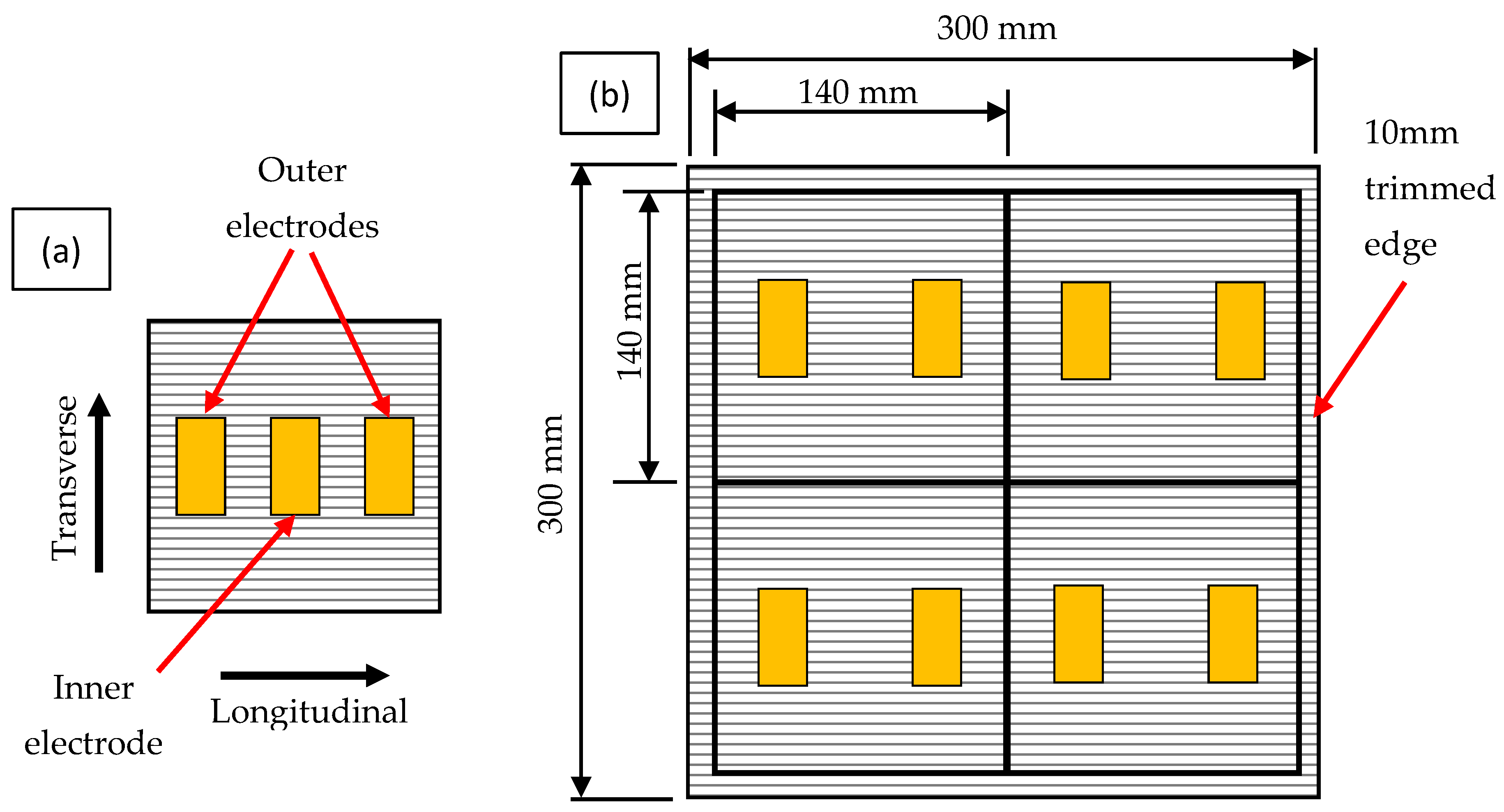
All samples used were square, measuring 140 mm × 140 mm or 140 mm × 70 mm, with electrode lengths ranging from 10 mm to 60 mm and electrode widths varying between 20 mm and 140 mm. These dimensions were cut from a 300 mm × 300 mm CFRP plate, with 10 mm trimmed from each edge to eliminate potentially low-quality material, as illustrated in Figure 2b. The remaining central section was divided into four equal samples, allowing four repetitions per test case to ensure consistency and repeatability in the evaluation.

2.3. Experimentation

Four samples were manufactured for each case listed in Table 1 to ensure repeatability and validate the experimental results. All the experiments in this work were conducted on UD thin-ply carbon fibre prepreg from SK Chemicals (Seongnam-si, South Korea) with the commercial name Skyflex USN020, having TC-33 carbon fibre and a K51 epoxy resin system with a cured ply thickness of 0.030 mm. The areal weight is 20 gsm with a fibre volume fraction of 40%, as specified in the manufacturer’s datasheet.
For the sample manufacturing, a standard prepreg composite procedure was used to stack up the plies. Two S-glass/epoxy prepreg plies, oriented at 0 cc and 90°, are placed at the bottom underneath the TC-33/epoxy prepreg layer to enhance the sample stiffness and provide electrical insulation for the carbon ply. The S-glass/epoxy prepreg supplied by Hexcel (Leicester, UK) with 913 resins has a nominal ply thickness of 0.155 mm. To ensure accessibility to the embedded electrodes, a top S-glass insulating layer was not applied over them. Despite the resulting laminate being asymmetric, only minimal warping was observed, and this had no significant effect on the electrical resistance measurements.
This negligible effect is attributed to the stiffness contribution of the two glass/epoxy backing plies, which dominate the bending rigidity of the thin carbon ply. Because of the use of thin-ply carbon layers, the asymmetry is minimal. The 0° carbon ply thickness is only 0.03 mm compared to 0.31 mm of 0° glass plies combined. Visual inspection confirmed that out-of-plane deformation was below 1 mm across the 140 mm sample length, which is insufficient to affect electrode contact or current distribution.
To ensure reliable electrical contact, 20-micron-thick copper electrodes were mounted on the top surface of the TC-33/epoxy prepreg ply using a non-stick template with stencil cutouts for accurate placement. Electrodes were pressed firmly by hand onto the prepreg layup, and the template was removed. Then, samples were manufactured following this stacking sequence E l e c t r o d e / 0 c a r b o n / 0 g l a s s / 90 g l a s s . Finally, layup and electrodes were vacuum-bagged for the autoclave curing cycle at 125 °C and 7 bar for 90 min. Co-curing provided intimate packing with the carbon fibres, minimising contact resistance, a method previously shown to yield stable low interface resistance [19]. Although contact resistance was not measured separately, its effect is reflected in a slightly higher experimental resistance compared to analytical and numerical predictions. Section Effect of Effective Width.
Electrical resistance was measured using embedded copper electrodes and a high-precision digital bench multimeter (HMC 8012, Fleet, UK; accuracy ±0.05–0.005%), following the two-point probe method. All specimens for each case were cut from the same 300 mm × 300 mm plate, trimmed by 10 mm on each edge, and divided into four equal samples to ensure repeatability. Electrodes were applied using the non-stick stencil with precision cut-outs to control their width, length, and alignment. Electrode edges were aligned with the specimen edges to preserve the intended 0°/90° fibre orientation. All specimens shared identical materials, stacking sequence, and autoclave cycle, differing only in the geometric parameters listed in Table 1.
Measurements were performed under identical conditions, yielding an average coefficient of variation of 1.8% for longitudinal resistance and 9.3% for transverse resistance (see Section Effect of Effective Width).

2.4. Finite Element Analysis

A 3D finite element model was created to simulate the electrical behaviour of UD CFRP laminates and to validate the analytical results using hexahedral elements of type Q3D78. To ensure the accuracy and efficiency of the simulations, a mesh sensitivity analysis was conducted using element sizes of 5 mm, 2.5 mm, 1 mm, and 0.5 mm. This analysis was conducted on a representative geometry consisting of a wide sample with narrow electrodes and a fibre orientation of 0° (longitudinal direction). The results showed that the 5 mm mesh resulted in 8.3% higher values than the analytical results, the 2.5 mm mesh resulted in 5.6% higher values, the 1 mm mesh resulted in 1.5% higher values, and the 0.5 mm mesh led to 1.2% higher values, when compared to the analytical results. Based on these findings, a mesh size of 1 mm was selected for all simulations, as it provides a suitable balance between computational efficiency and solution accuracy, providing adequate mesh quality while maintaining a reasonable number of elements and manageable computational cost.
The bottom glass layers used in the experimentation are not modelled because their electrical conductivity is very low. CFRP layers are modelled as an orthotropic homogeneous material with different resistivity values along the fibre and transverse directions listed in Table 2. Longitudinal and transverse resistivities of TC-33/K51 epoxy were experimentally measured using the two-probe method in the evaluated geometries. Copper electrodes are modelled on the top surface of the UD CFRP with an ideal zero-contact resistance electrical connection with the CFRP layer.
An electrical potential difference of 0.6 V was applied at the centre point of the top surface of each electrode to simulate the electrical resistance measurement between the probes. The choice of 0.6 V reflects the voltage used in bench multimeter measurements and was selected to maintain a low, safe electric field and minimal power dissipation. This ensures operation within the linear, Ohmic regime, avoiding significant Joule heating. Given the linear conduction model, constant orthotropic conductivity, and ideal electrode–laminate contact assumed in the finite element setup, the resulting resistance R = V/I is independent of the excitation magnitude. Therefore, voltage optimisation is unnecessary, and 0.6 V serves as a representative and numerically stable value consistent with the experimental conditions. The resulting reaction current (I), defined as the total current flowing through the composite in response to the applied voltage, was recorded. The electrical resistance ( R ) was calculated using Ohm’s law R = V / I . All simulations were conducted using the 2-pp method, which captures the resistance across the material, including the contact resistance based on the ideal electrode–material interface.

3. Results

Effect of Effective Width

To study the effective width dependency on fibre direction, two similar models with fibre direction as the only difference were studied initially. Numerical models can help to visualise the electrical path between electrodes in the longitudinal and transverse directions, helping to understand how parameters such as sample and electrode width influence the electrical resistance in UD CFRP. The suitable variable to visualise the current flow path is the electric potential gradient (EPG), defined as the rate of change in electric potential with respect to distance in different directions [23]. EPG is related to the electric flux, giving a picture of the dominant electrical current path.
Figure 3 illustrates the EPG distributions in both the longitudinal and transverse directions for several scenarios, including: (a) wide sample with wide electrodes, (b) wide sample with narrow electrodes, and (c) narrow sample with narrow electrodes. These scenarios help to illustrate how fibre orientation and electrode geometry influence the current flow and consequently the effective width used in resistance calculations.
For the longitudinal direction, as illustrated in Figure 3a–c, the EPG distribution, highlighted in orange, clearly demonstrates that the electrical current predominantly flows between the electrodes and depends on the electrode width, irrespective of the overall sample width. This behaviour is attributed to the highly anisotropic electrical conductivity of the UD CFRP, where the carbon fibres provide a continuous, least-resistance path for current flow. The current is primarily carried by fibres that are parallel, directly aligned, and connected between the two electrodes. As a result, the effective width governing the longitudinal electrical resistance corresponds to the electrode width, as it defines the actual region contributing to current conduction along the fibre direction.
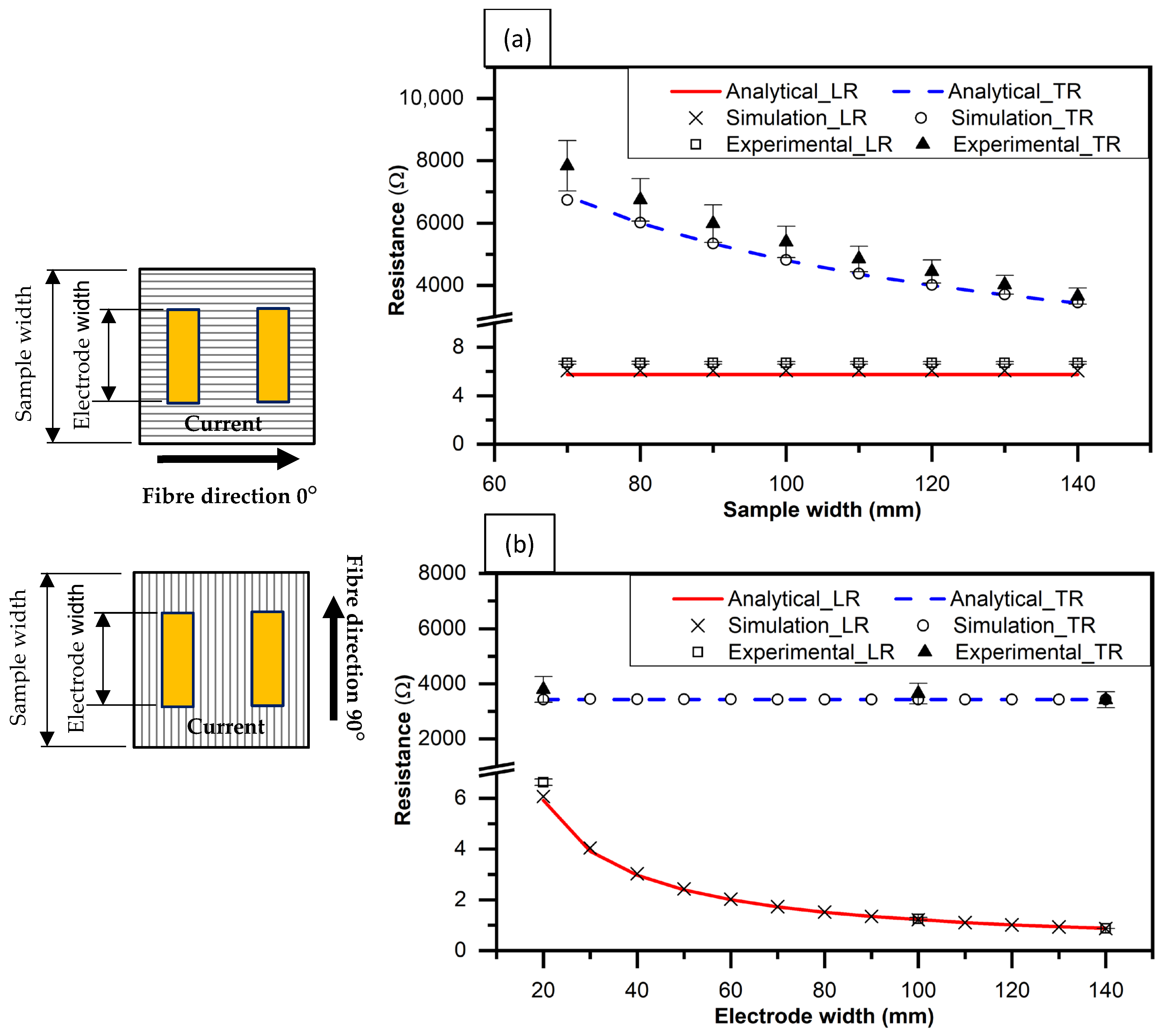
On the other hand, the EPG results for the transverse direction are shown in red in Figure 3d–f, indicating that the electrical current distributes across the entire sample width, regardless of the electrode width. In this orientation, the main conduction mechanism is through inter-fibre contacts within the polymer matrix, which offer significantly higher resistance compared to the fibre direction. Due to this, the current must traverse laterally across the fibres, but since the fibre direction is much more conductive, the current travels easily across the entire width of the composite sample. Consequently, for the purpose of the proposed analytical model, the effective width in the transverse resistance direction case is defined by the sample width, rather than the electrode width. The electrical resistance was measured and calculated for different CFRP and electrode widths in both the longitudinal and transverse fibre directions, as summarised in Table 1. Analytical results based on the proposed approach and incorporating the appropriate effective width for each fibre orientation are compared in Figure 4 and Table 3.
As shown in Figure 4a, longitudinal resistance remains unaffected by changes in sample width, indicating that current conduction is confined to the region defined by the electrode width, where LR and TR refer to longitudinal resistance and transverse resistance, respectively. In contrast, transverse resistance decreases with increasing sample width, as the current path expands across a larger inter-fibre area. Figure 4b demonstrates that longitudinal resistance decreases with increasing electrode width, while in this case, the transverse resistance remains constant, further confirming that in the transverse direction, the current distribution is governed by the full sample width rather than the electrode width. These findings validate the uniform electrical current assumption used in the analytical approach and highlight the orientation-dependence of resistance behaviour in UD CFRP laminates.
The numerical and analytical results have shown excellent agreement, with differences below 3%, confirming that the electrical current is dominated by a single direction in UD CFRP when surface electrodes are employed. This validates the use of an appropriate effective width in each case for predicting resistance. On the other hand, the average experimental resistances are slightly higher than both the simulation and analytical results because of the inclusion of the contact interface resistance between fibres and electrodes, which is inherent in the experimental setup but not in the simulation or analytical results.
Moreover, the average experimental coefficient of variation was found to be 1.8% for longitudinal and 9.3% for transverse resistance, suggesting the repeatability of the results, particularly in the longitudinal direction. This higher variability in transverse resistance arises because conduction occurs through inter-fibre contacts within the polymer matrix, which are strongly influenced by local microstructural variations such as fibre spacing and resin distribution. In contrast, longitudinal conduction follows continuous fibres, resulting in more stable and repeatable measurements. For practical implementation, this suggests that transverse resistance measurements can typically show higher scatter, and interpretation of data should be taken with more care.
Therefore, the analytical model is validated by both simulation and experimental data across different electrode and sample widths. This confirms the reliability of the proposed analytical approach for predicting the electrical resistance in UD CFRP laminates.
To study the effective width dependency on fibre direction with an electrode width offset, two similar models with fibre direction as the only difference were studied initially. Then, to nondimensionalise the geometry parameters, the “width offset ratios” are proposed as a new parameter, which it is defined as the ratio between the electrode width offset and the electrode width. For the samples with no electrode width offset, a perfect alignment of electrodes in the fire direction is denoted “0 width offset ratio”. In contrast, full offset values equal to or above the “1.0 width offset ratio” refer to the case where both electrodes are no longer directly connected by fibres.
The longitudinal direction was the main current path for the width offset ratios lower than 1.0, due to the fibres connecting both electrodes in the overlapping electrode width. The EPG distribution is shown in Figure 5a, illustrating the current path for these scenarios. Therefore, the effective width used for Figure 5 is defined as the overlap width between electrodes for these scenarios.
The scenarios with a width offset ratio higher than 1.0 have their main current path in the transverse direction, as shown in Figure 5b in the EPG distribution. The electrical conduction happens through the inter-fibre contacts, since no fibres directly connect the electrodes, so the electrical resistance depends on the sample width. In such cases, the effective width governing electrical resistance should be defined by the entire sample width.
The electrical resistance for different electrode width offsets can be calculated using the proposed analytical approach by applying the suitable effective width for each configuration. For electrode configurations with an electrode width offset less than or equal to 1, the effective width corresponds to the electrode width. In contrast, for configurations with an offset greater than 1, the effective width equals the sample width. Figure 6 and Table 4 compare numerical, analytical, and experimental resistance values in terms of the resistance ratio across different electrode width offsets.
The analytical results show good agreement with both numerical and experimental results across most of the evaluated range. Notably, all three methods follow a consistent trend, except near a width offset ratio of 1.0, as shown in Figure 6. This behaviour arises from the transition in the dominant current path from longitudinal to transverse conduction. For width offset ratios approaching 1.0, the overlap between electrodes decreases, significantly reducing the number of carbon fibres directly connecting the electrodes. When the overlap reaches zero, i.e., at a width offset of 1.0, the analytical resistance increases non-linearly, tending toward infinity due to the lack of conductive paths as the effective width used in the analytical equation approaches zero. For width offsets larger than 1.0, the current must flow through the polymer matrix and inter-fibre regions, which have substantially higher resistivity than the carbon fibres.
Therefore, this transition reflects a fundamental change in the conduction mechanism, from fibre-dominated to inter-fibre-contact conduction, explaining the sharp rise in resistance predicted by the analytical approach near this critical width offset ratio.
For width offsets greater than 2.0, the analytical values align closely with both numerical and experimental values, showing a linear increase with increasing width offset, as illustrated in Figure 6. In this regime, the dominant conductivity mechanism is through inter-fibre contacts, as no continuous carbon fibre bridges the electrodes. As a result, the effective width is the entire sample width, and the analytical approach captures this behaviour, thereby validating the proposed approach for scenarios with large electrode misalignment.
Importantly, in these cases, the only parameter that varies with the width offset ratio is the distance between electrodes, while other geometrical parameters remain constant. This linear relationship between electrode distance and electrical resistance, shown for all three evaluated methods, further supports the reliability of the analytical approach in predicting resistance under significant electrode offset cases.
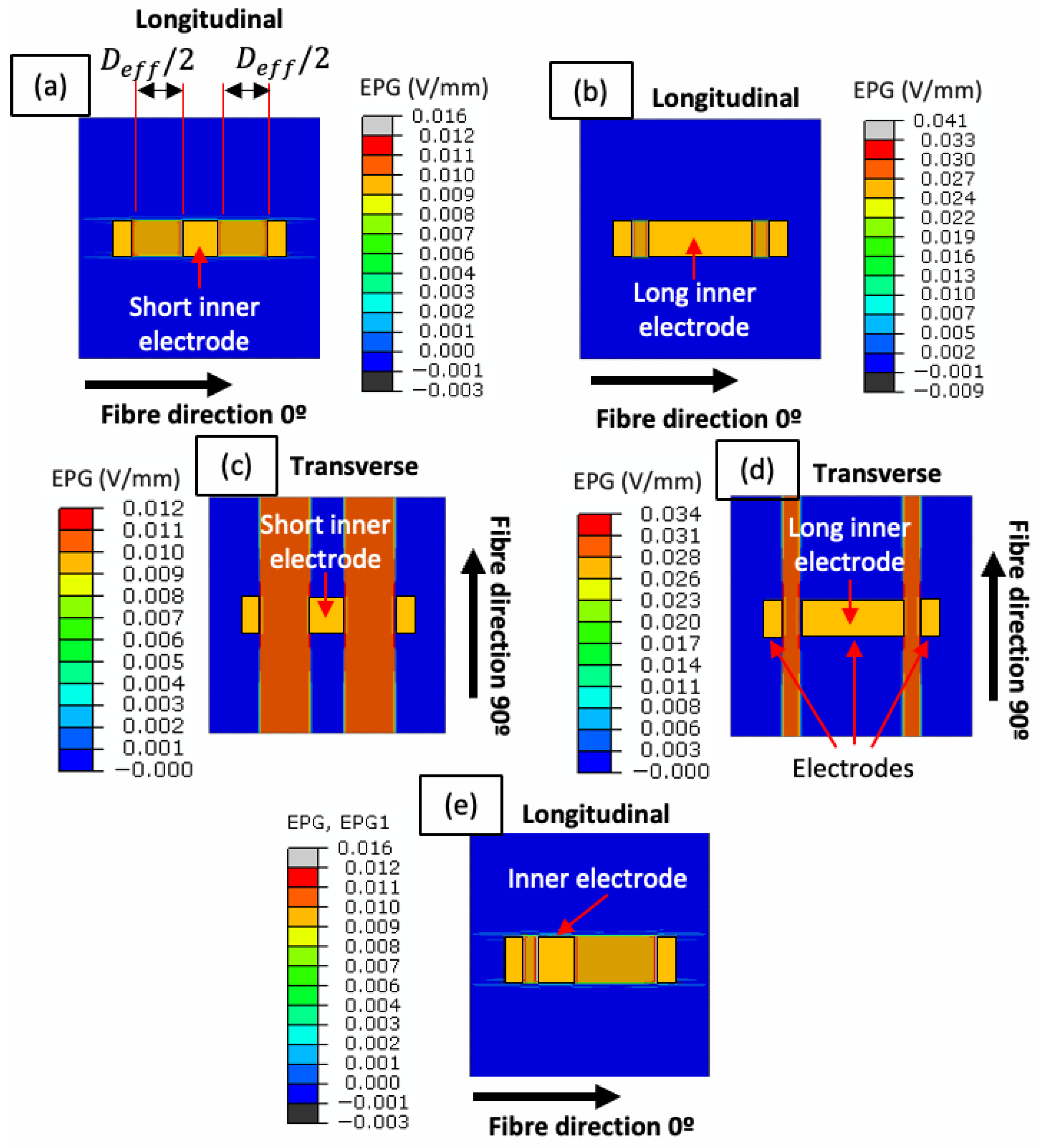
The effect of other electrodes interfering with the electrical current between the two main electrodes is studied by placing an inner electrode between the two outer electrodes. Samples with aligned electrodes in the longitudinal direction show a current path only between the probe electrodes, as shown in Figure 7a,b; the inner electrode interferes with the electrical current, acting as a “bridge” between the two probe electrodes due to the significantly higher copper conductivity compared with carbon fibre conductivity. The electrical current goes through the path with lower resistivity or higher conductivity. The effect of a third electrode on the transverse resistance is similar to the one presented for the longitudinal resistance. Figure 7c,d show the EPG distribution for different electrode lengths and widths, indicating that the inner electrode creates an electrical bridge between the probe electrodes. Therefore, the “bridge effect” refers to the phenomenon where an inner copper electrode, placed between two probed electrodes, provides a low-resistance path that partially bypasses the CFRP material.
A new definition of distance between electrodes for samples with three electrodes is proposed to predict the electrical resistance between two surface electrodes on a UD CFRP plate. The effective distance, D e f f , is defined as the inner distance between the probed electrodes minus the length of the third electrode, as shown schematically in Figure 7a.
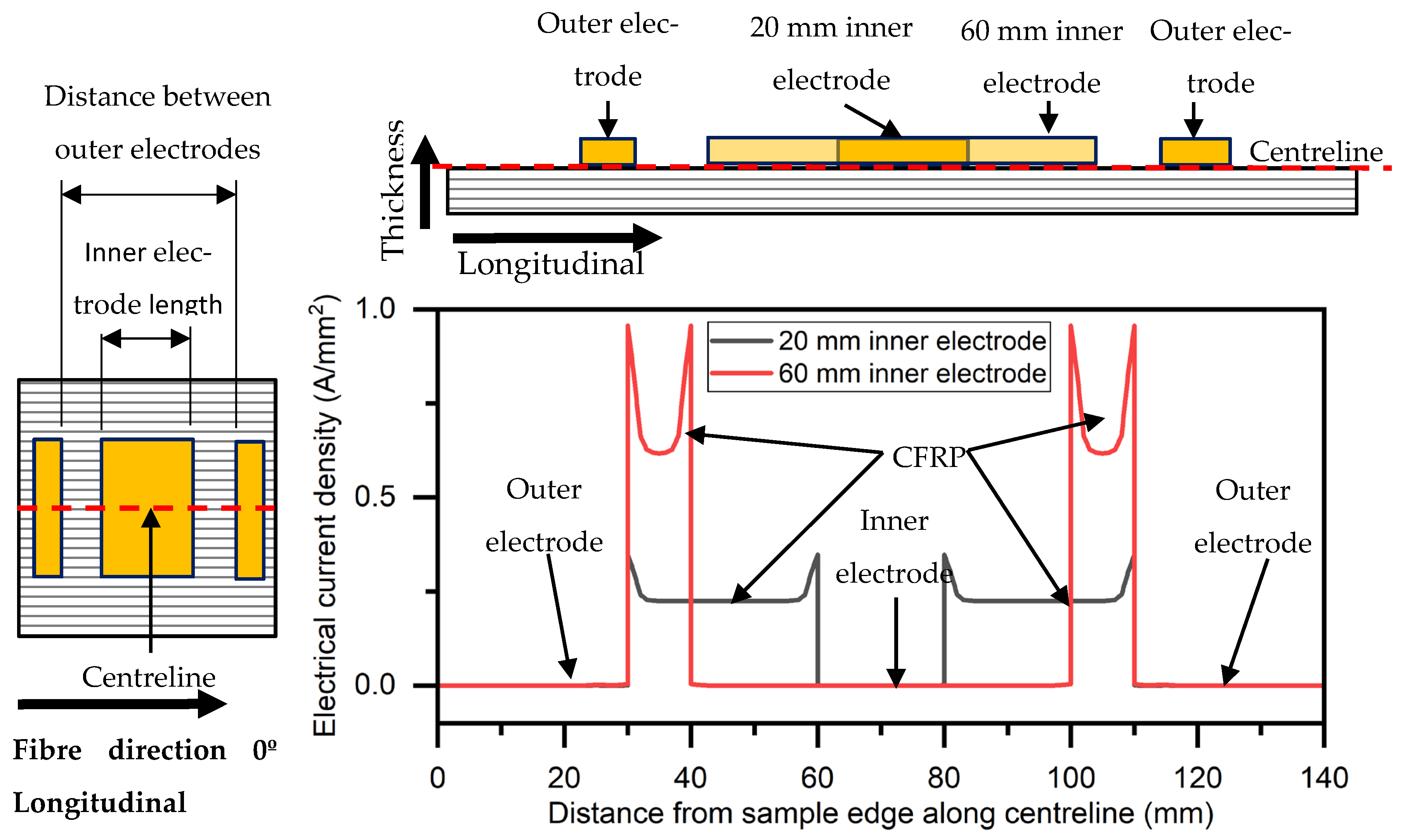
To validate the “bridge effect” of the copper electrodes, Figure 8 presents the electrical current density (ECD) profile in the CFRP layer along the specimen’s centreline on the top surface of the CFRP layer for inner electrode lengths of 20 mm and 60 mm, as shown schematically by a red dashed line. The electrical current density (ECD) is nearly zero outside the inner edges of the outer copper electrodes, where the voltage is applied, due to copper’s low electrical resistivity. As the current transitions into the carbon fibre region, the ECD increases mostly around the inner edges of the copper electrodes. Upon reaching the inner copper electrode, the ECD sharply decreases along its full length, demonstrating the bridge effect, where current preferentially flows through the low-resistance copper, bypassing the higher-resistance composite path. This behaviour confirms that electrical current preferentially flows through the material with the lowest resistivity, in this case, copper, effectively bypassing the higher-resistance carbon fibre path.
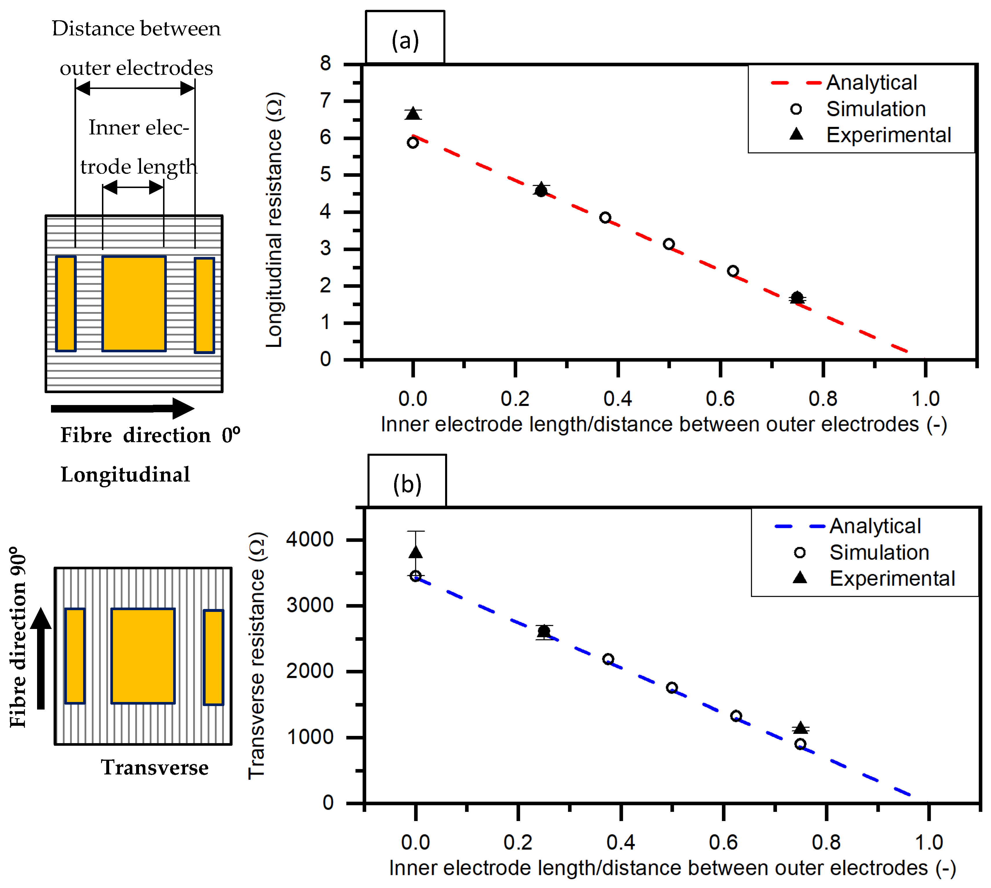
Using the effective distance, D e f f , between electrodes, the electrical resistance has been calculated using the proposed analytical approach for the longitudinal and transverse directions. Analytical, numerical, and experimental results are shown in Figure 9 and Table 5, presenting a good agreement between them and illustrating the resistance for different electrode lengths. The results show a linear relationship between the measured electrical resistance and the ratio of the inner electrode length to the distance between the inner edges of the probed electrodes. As the inner electrode length increases, the electrical resistance decreases, attributed to the “bridge effect” of the copper electrode enhancing current flow across the laminate.
The bridge effect was experimentally validated by comparing resistance values for configurations with and without an inner electrode of different lengths (20 mm and 60 mm), which showed a clear reduction in resistance as the inner electrode length increased (Figure 9). This trend aligns with the simulation results (Figure 8), confirming that the inner electrode provides a low-resistance path between the outer electrodes. Simulations indicated minimal unintended current leakage within the CFRP material, measured at 0.00038 A/mm2 and 0.00037 A/mm2 for inner electrode lengths of 20 mm and 60 mm, respectively. These values are negligible compared to the current densities on the copper electrodes, which were 0.32 A/mm2 and 0.89 A/mm2 for the same configurations.
Additional simulations were conducted for configurations in which the inner electrode was laterally offset along the electrode length direction. The results indicate that such misalignment does not significantly affect either the longitudinal or transverse electrical resistance, as shown in Figure 7e.

4. Discussion

Compared to more complex approaches, such as resistor-network models [14] or microstructure-based formulations [18], the proposed method prioritises simplicity and computational efficiency. Resistor-network models can capture the effect of local fibre contact effects and microstructural variability, offering high accuracy at the cost of significant input data requirements (e.g., fibre distribution, contact resistances) and computational effort. In contrast, our approach uses only two geometric parameters, effective width and effective electrode distance, combined with orthotropic resistivity, achieving prediction errors below 5% compared to FEM while remaining easy to implement and scalable. This trade-off between simplicity and accuracy makes the proposed model particularly suitable for the real-time monitoring and design of electrode arrays in industrial CFRP structures.
The proposed analytical equation can predict the electrical resistance between two electrodes located anywhere on the top surface of a UD CFRP plate with fibres oriented at 0° or 90°, considering the electrode and sample size. Finite element models and experimental results are generally in agreement with analytical resistances, validating the assumption of uniform electrical current in such cases. In addition, experimental tests presented a low scatter, indicating good repeatability in the results.
It should be noted that the proposed model assumes a uniform fibre volume fraction across the laminate. In practice, manufactured UD CFRP often exhibits microstructural inhomogeneity, such as local variations in fibre packing and resin-rich regions. These features have a negligible effect on longitudinal resistance, which is dominated by continuous fibres, but can significantly influence transverse resistance, where conduction relies on inter-fibre contacts. This variability likely contributes to the higher experimental CV% observed in transverse measurements compared to longitudinal ones. In this paper, the effect of microstructure on the variation in resistivity, especially in the transverse direction, is not studied, and a uniform resistivity is assumed in all models.
The higher CV% observed in transverse resistance measurements (compared to longitudinal) reflects the sensitivity of inter-fibre conduction to local microstructural variations. However, SHM typically relies on monitoring changes in a sensor’s resistance over time relative to its original baseline. Therefore, even with variability, the transverse resistance can still be used for SHM. In practice, though, greater consistency is desirable, and higher variability suggests that larger detection thresholds may be required for transverse measurements. For example, if healthy specimens exhibit a CV of approximately 10%, resistance changes of similar magnitude cannot be confidently attributed to damage; consequently, thresholds should exceed this baseline variability to ensure reliable interpretation.
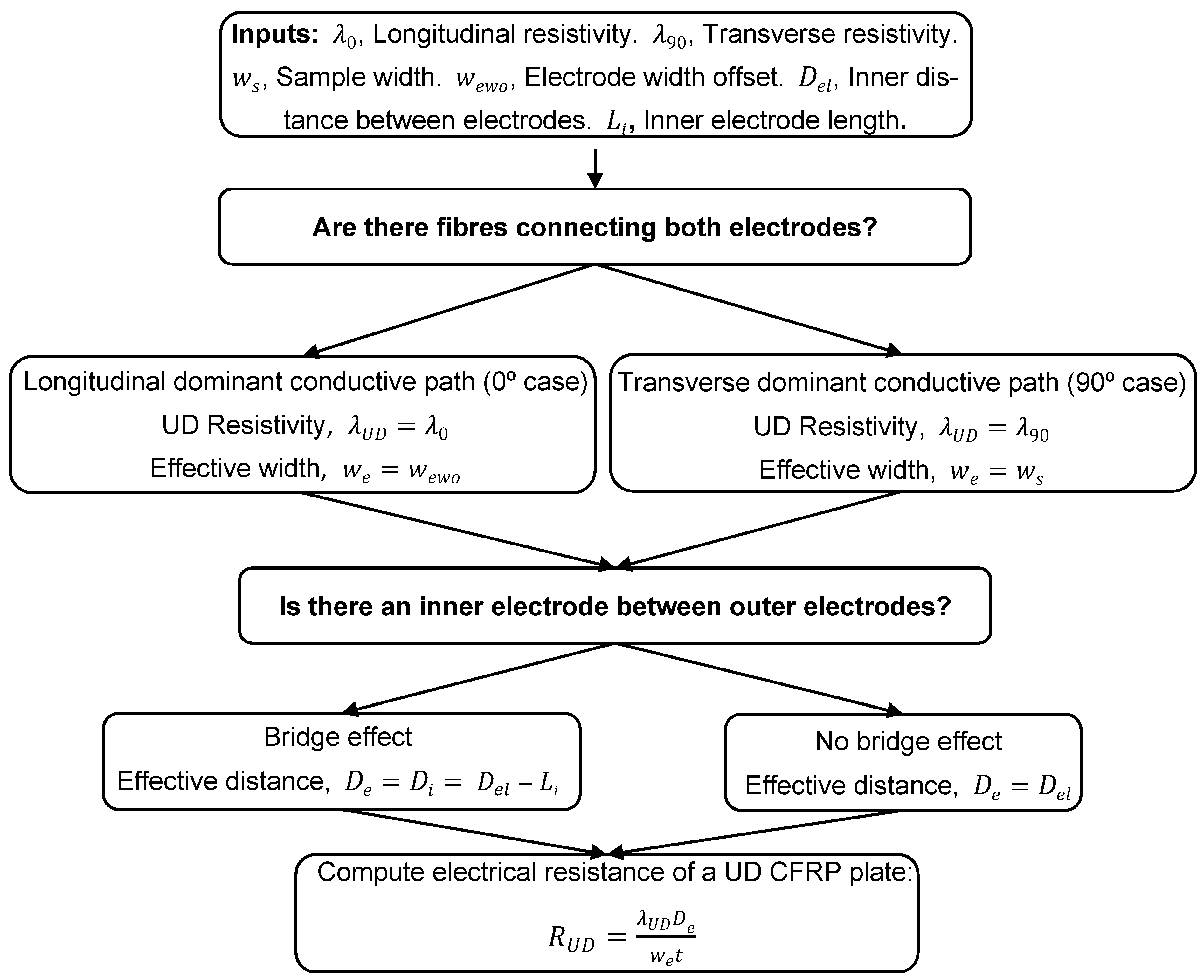
For practical implementation, two geometry-dependent parameters are introduced to modify the simple single-axis resistance equation to calculate the electrical resistance between two small surface electrodes on a UD CFRP plate: the effective width ( W e ) and the effective distance ( D e ). These parameters allow the simplified resistance given in Equation (2) to capture the influence of electrode geometry and misalignment on surface resistance. The calculation of the electrical resistance can be summarised in a four-step procedure, as follows:
Step 1: Identify the principal conduction path and select λ U D
The first step is to determine whether the dominant current flow occurs along the fibres, a longitudinal conduction path, or across them, a transverse conduction path. If the electrodes share an overlap region where fibres directly connect both electrodes, the longitudinal path dominates, therefore λ U D = λ 0 ; otherwise, the transverse path governs conduction and λ U D = λ 90 .
Step 2: Assign the effective width, W e
The effective width represents the cross-sectional width actively carrying current.
  • Longitudinal conductive path: W e equals the electrode width overlap ( W e w o ), as only fibres bridging both electrodes contribute significantly to conduction.
  • Transverse conductive path: W e equals the full specimen width ( W s ), since current spreads through inter-fibre contacts across the entire laminate.
Step 3: Compute the effective distance, D e
The effective distance is the inner-edge separation between the two electrodes, representing the actual length of the current path.
  • Without inner electrode: D e remains constant for all configurations without additional electrodes as D e l , the inner distance between electrodes.
  • With an inner electrode: D e is reduced by the length of the bridging electrode ( L i ). Therefore, the effective distance with an inner electrode ( D i ) is defined as D i = D e l L i .
Step 4: Evaluate the resistance
Using these definitions, the surface resistance is calculated using Equation (2).
A condensed, user-oriented version of Steps 1–4 is depicted in Figure 10 as a decision-tree. The same rules are used in the FE models and experiments when comparing predicted and measured resistances in Section 3 and Section 4.
Equation (2) shows that the surface electrical resistance of a UD CFRP plate ( R U D ) increases linearly with the D e and decreases as the W e becomes larger. In cases of electrode misalignment, R U D exhibits a sharp rise when the W e w o approaches zero, reflecting the transition from fibre-dominated to inter-fibre conduction. For transverse configurations, increasing the specimen width reduces R U D , whereas changes in electrode width have negligible effect. Conversely, in longitudinal configurations, enlarging the W e w o significantly lowers R U D , while W s has little influence on resistance.
The simplified expression D i = D e l L i does not assume that the inner electrode is centrally located between the two outer electrodes, and the inner electrode can be offset and not necessarily at the middle of the outer electrodes. Additional simulations with the inner electrode offset along its length direction revealed that this misalignment does not influence the measured resistance. This outcome confirms the robustness of the proposed analytical model with respect to variations in inner electrode positioning.
Previous studies in UD CFRPs have focused on analysing single-axis electrical resistance and its prediction using analytical equations, investigating only longitudinal, transverse, or through-thickness resistance in isolation from one another [13]. This work takes a step forward in studying, predicting, and validating the electrical resistance for surface electrodes on a UD CFRP plate for the longitudinal and transverse directions using the proposed analytical approach.
The results indicated that the surface resistance shows a single-axis behaviour due to the anisotropic electrical properties of UD CFRPs, dominated by significantly higher longitudinal conductance. This leads to a uniform current distribution between the electrodes, which supports the application of the proposed analytical equation. However, in the presence of electrode misalignment, the influence of fibre conductivity on the longitudinal resistance decreases. In such cases, the dominant conductive path shifts towards inter-fibre contacts, and the relevant parameter changes from the electrode width to the whole sample width, resulting in behaviour more characteristic of transverse resistance. It should be noted that the present analytical approach is limited to rectangular electrodes. Rectangular electrodes are the most common geometry found in the literature. For other shapes of electrodes, a similar approach to finding the effective width could be applied, but verification of such a model for non-rectangular geometries has not been studied in this paper due to a lack of interest in such geometries.
While the present work does not include damaged specimens, the validated baseline model enables future integration with damage detection strategies. In practice, resistance anomalies can be compared against the predicted values from this model to identify and localise damage. This approach supports real-time SHM by distinguishing between geometric effects and material degradation.
This work aimed to evaluate the use of the proposed analytical approach, based on the assumption of uniform current distribution, for predicting the electrical resistance between two electrodes placed anywhere in a UD CFRP plate. The ultimate goal is to enable the future detection of damage or defects in CFRPs by identifying differences between experimental resistance measurements and theoretical predictions. Then, potentially, our results could open a new avenue of study on quality control of UD CFRP materials and structures, which will provide information to determine if a material has factory defects or if a structure has defects that can compromise its performance. Nevertheless, further investigation needs to be performed to study the effect of other fibre orientations and laminates, such as cross-ply and quasi-isotropic laminates, on the electrical resistance of UD CFRPs, with the intention of determining damage or defects in UD CFRPs.

5. Conclusions

The proposed analytical equation, based on the assumption of uniform current flow, can predict the surface electrical resistance between two electrodes located anywhere on a UD plane in a CFRP plate with 0° or 90° fibre orientation with the measuring electrodes. This equation was validated through numerical simulations and experimental testing. Key parameters investigated include measuring electrode direction and factors such as sample size, electrode placement, and varying middle electrodes.
This work introduces an equation that uses two key parameters to predict the surface electrical resistance in UD CFRP at 0° or 90° fibre orientation: the effective width ( w e ) and the effective distance between electrodes ( D e ). w e accounts for variations in electrode width, sample width, and any offset between electrodes. In comparison, D e is associated with the influence of an inner electrode on the current path. These parameters were identified for each evaluated scenario, and a systematic procedure was developed to determine and apply them for resistance prediction.
The proposed analytical equation can predict the surface electrical resistance in UD CFRP plates at 0° or 90° fibre orientation because the electrical properties for each direction are significantly different. Therefore, there is only one main electrical current path flow between two electrodes in a UD plate, which could be along the fibres or the inter-fibre contacts, and depends on the fibre orientation.
Future work could extend the proposed analytical approach to non-rectangular electrode geometries. This will require defining the effective width for more generic geometries and validating it through dedicated simulations and experiments. Additionally, laminates with more complex fibre orientations (e.g., cross-ply or quasi-isotropic) will need a more complex analytical framework supported by numerical and experimental validation.

Author Contributions

J.D.A.: Software, Methodology, Conceptualization, Writing—original draft, Visualisation. M.J.: Conceptualization, Writing—review and editing, and Supervision. S.A.M.: Conceptualization, Writing—review and editing, Funding acquisition. A.H.: Writing—review and editing, and Supervision. All authors have read and agreed to the published version of the manuscript.

Funding

This research received no external funding.

Data Availability Statement

Data will be made available on request.

Acknowledgments

J. David Acosta gratefully acknowledges Minciencias-Colombia for funding his doctoral studies through a forgivable educational loan under the call “Doctorados en el exterior No. 885”. The authors acknowledge Hexcel for supplying glass prepreg for this research.

Conflicts of Interest

The authors declare no conflicts of interest.

References

  1. Ostachowicz, W.; Güemes, A. New Trends in Structural Health Monitoring; Springer Science & Business Media: Berlin/Heidelberg, Germany, 2013; Volume 542. [Google Scholar]
  2. Dafydd, I.; Khodaei, Z.S. Analysis of barely visible impact damage severity with ultrasonic guided Lamb waves. Struct. Health Monit. 2020, 19, 1104–1122. [Google Scholar] [CrossRef]
  3. Kinet, D.; Mégret, P.; Goossen, K.W.; Qiu, L.; Heider, D.; Caucheteur, C. Fiber Bragg grating sensors toward structural health monitoring in composite materials: Challenges and solutions. Sensors 2014, 14, 7394–7419. [Google Scholar] [CrossRef]
  4. Sofi, A.; Regita, J.J.; Rane, B.; Lau, H.H. Structural health monitoring using wireless smart sensor network—An overview. Mech. Syst. Signal Process. 2022, 163, 108113. [Google Scholar] [CrossRef]
  5. Bagavathiappan, S.; Lahiri, B.B.; Saravanan, T.; Philip, J.; Jayakumar, T. Infrared thermography for condition monitoring—A review. Infrared Phys. Technol. 2013, 60, 35–55. [Google Scholar] [CrossRef]
  6. Addepalli, S.; Zhao, Y.; Roy, R.; Galhenege, W.; Colle, M.; Yu, J.; Ucur, A. Non-destructive evaluation of localised heat damage occurring in carbon composites using thermography and thermal diffusivity measurement. Measurement 2019, 131, 706–713. [Google Scholar] [CrossRef]
  7. Todoroki, A.; Tanaka, M.; Shimamura, Y. High performance estimations of delamination of graphite/epoxy laminates with electric resistance change method. Compos. Sci. Technol. 2003, 63, 1911–1920. [Google Scholar] [CrossRef]
  8. Wang, X.; Wang, S.; Chung, D.D.L. Sensing damage in carbon fiber and its polymer-matrix and carbon-matrix composites by electrical resistance measurement. J. Mater. Sci. 1999, 34, 2703–2713. [Google Scholar] [CrossRef]
  9. Gigliotti, M.; Lafarie-Frenot, M.C.; Lin, Y.; Pugliese, A. Electro-mechanical fatigue of CFRP laminates for aircraft applications. Compos. Struct. 2015, 127, 436–449. [Google Scholar] [CrossRef]
  10. Wen, J.; Xia, Z.; Choy, F. Damage detection of carbon fiber reinforced polymer composites via electrical resistance measurement. Compos. B Eng. 2011, 42, 77–86. [Google Scholar] [CrossRef]
  11. Todoroki, A. New analytical method for electric current and multiple delamination cracks for thin CFRP cross-ply laminates using equivalent electric conductance. Adv. Compos. Mater. 2016, 25, 87–101. [Google Scholar] [CrossRef]
  12. Todoroki, A.; Tanaka, M.; Shimamura, Y. Measurement of orthotropic electric conductance of CFRP laminates and analysis of the effect on delamination monitoring with an electric resistance change method. Compos. Sci. Technol. 2002, 62, 619–628. [Google Scholar] [CrossRef]
  13. Abry, J.C.; Bochard, S.; Chateauminois, A.; Salvia, M.; Giraud, G. In situ detection of damage in CFRP laminates by electrical resistance measurements. Compos. Sci. Technol. 1999, 59, 925–935. [Google Scholar] [CrossRef]
  14. Yu, H.; Heider, D.; Advani, S. A 3D microstructure based resistor network model for the electrical resistivity of unidirectional carbon composites. Compos. Struct. 2015, 134, 740–749. [Google Scholar] [CrossRef]
  15. Gadomski, J.; Pyrzanowski, P. Experimental investigation of fatigue destruction of CFRP using the electrical resistance change method. Measurement 2016, 87, 236–245. [Google Scholar] [CrossRef]
  16. Roh, H.D.; Oh, S.Y.; Park, Y.B. Self-sensing impact damage in and non-destructive evaluation of carbon fiber-reinforced polymers using electrical resistance and the corresponding electrical route models. Sens. Actuators A Phys. 2021, 332, 112762. [Google Scholar] [CrossRef]
  17. Wang, D.; Wang, S.; Chung, D.D.L.; Chung, J.H. Sensitivity of the two-dimensional electric potential/resistance method for damage monitoring in carbon fiber polymer-matrix composite. J. Mater. Sci. 2006, 41, 4839–4846. [Google Scholar] [CrossRef]
  18. Xia, Z.H.; Curtin, W.A. Modeling of mechanical damage detection in CFRPs via electrical resistance. Compos. Sci. Technol. 2007, 67, 1518–1529. [Google Scholar] [CrossRef]
  19. Malik, S.A.; Jalalvand, M.; Wadge, M.D.; Acosta, J.D.; Felfel, R.M. Robust Electrical Contact with Low Interface Resistance Using Embedded Co-cured Electrodes in Carbon Fibre Composites. Appl. Compos. Mater. 2025, 32, 2625–2652. [Google Scholar] [CrossRef]
  20. Todoroki, A.; Suzuki, K.; Mizutani, Y.; Matsuzaki, R. Durability Estimates of Copper Plated Electrodes for Self-sensing CFRP Composites. J. Solid Mech. Mater. Eng. 2010, 4, 610–620. [Google Scholar] [CrossRef]
  21. Wang, S.; Chung, D.D.L.; Chung, J.H. Self-sensing of damage in carbon fiber polymer-matrix composite by measurement of the electrical resistance or potential away from the damaged region. J. Mater. Sci. 2005, 40, 6463–6472. [Google Scholar] [CrossRef]
  22. Cagáň, J.; Pelant, J.; Kyncl, M.; Kadlec, M.; Michalcová, L. Damage detection in carbon fiber–reinforced polymer composite via electrical resistance tomography with Gaussian anisotropic regularization. Struct. Health Monit. 2019, 18, 1698–1710. [Google Scholar] [CrossRef]
  23. Ellingson, S.W.; Walz, A.; Browder, R. Electromagnetics; Volume, No. v. 1. in Open Textbook Library. Virginia Tech University Libraries, 2018. Available online: https://books.google.co.uk/books?id=S3iwtAEACAAJ (accessed on 5 August 2025).
Figure 1. Schematic of electrical resistance measurement using the two-probe method for (a) single-axis and (b) surface electrode array configurations. Arrows indicate the fibre direction.
Jcs 09 00615 g001
Figure 2. Schematic of (a) a sample with an inner electrode and (b) the cutting layout of the sample from the original CFRP plate. Arrows indicate the fibre direction.
Jcs 09 00615 g002
Figure 3. Electric potential gradient (EPG) distribution for longitudinal and transverse fibre orientations. (ac) Longitudinal fibre direction (0°): Electrical potential gradient (EPG) distributions for three configurations. (a) Wide sample with wide electrodes, (b) wide sample with narrow electrodes, and (c) narrow sample with narrow electrodes. (df) Transverse fibre direction (90°): EPG distribution for the same configurations.
Jcs 09 00615 g003
Figure 4. Influence of sample and electrode width on electrical resistance. (a) Longitudinal and transverse resistance vs. sample width. (b) Longitudinal and transverse resistance vs. electrode width.
Jcs 09 00615 g004
Figure 5. Electric potential gradient (EPG) distribution for different electrode width offsets: (a) offset ratio < 1, indicating partial overlap, and (b) offset ratio > 1, indicating misalignment beyond direct overlap.
Jcs 09 00615 g005
Figure 6. Electrical resistance vs. electrode width offset ratio. Comparison of analytical, numerical, and experimental resistance values across a range of electrode width offset ratios.
Jcs 09 00615 g006
Figure 7. Electric potential gradient (EPG) distribution for different inner electrode lengths in the (a,b) longitudinal and (c,d) transverse directions. (e) For a non-centred inner electrode.
Jcs 09 00615 g007
Figure 8. Numerical simulation of electrical current density distribution for inner electrode lengths of 20 mm and 60 mm.
Jcs 09 00615 g008
Figure 9. Electrical resistance for different inner electrode lengths in the (a) longitudinal and (b) transverse directions.
Jcs 09 00615 g009
Figure 10. Workflow to evaluate surface resistance between two surface electrodes on a UD CFRP laminate.
Jcs 09 00615 g010
Table 1. Evaluated sample configuration and dimensions.
Type of SampleCFRP/Electrode ConfigurationCFRP Length (mm)CFRP Width (mm)Electrode Width (mm)Electrode Length (mm)
Varying the electrode and sample width in the longitudinal and transverse directionsWide sample, wide electrodes14012014010
Wide sample, narrow electrodes1401202010
Narrow sample, narrow electrodes140702010
Varying the electrode width offset with electrode overlappingWidth offset of 0.2, 0.6, and 1.070702010
Varying the electrode width offset, without electrode overlappingWidth offset of 2.0, 3.0, and 4.0701402010
Varying inner-electrode width in the longitudinal and transverse directionsShort inner electrode1401402020
Long inner electrode1401402060
Table 2. Electrical properties.
MaterialLongitudinal Resistivity [Ωmm]Transverse Resistivity [Ωmm]
TC33/K51 epoxy a0.0425355.7
Copper1.68 × 10−5
a Experimentally obtained.
Table 3. Summary of experimental and analytical electrical resistance values for various electrode and sample configurations in UD CFRP laminates.
Longitudinal (0°)Transverse (90°)
Experimental (Ω) [CV%]Analytical (Ω)Experimental (kΩ) [CV%]Analytical (kΩ)
Wide sample with wide electrodes1.25 [4.64]1.213.65 [10.15]3.42
Wide sample with narrow electrodes6.63 [1.83]6.073.79 [12.36]3.42
Narrow sample with narrow electrodes6.39 [8.7]6.077.93 [5.91]6.86
Table 4. Analytical and experimental electrical resistance values for UD CFRP samples with varying electrode width offset ratios ranging from 0.0 to 5.0.
Width Offset Ratio (−)Experimental (Ω) [CV%]Analytical (Ω)
06.63 [0.87]6.07
0.26.74 [4.36]7.59
0.610.5 [1.73]15.18
148 [8.28]
2881.79 [9.23]857.14
31864.52 [6.82]1714.28
53656.45 [7.37]3428.57
Table 5. Analytical and experimental electrical resistance values for UD CFRP samples with varying inner electrode lengths relative to the distance between outer electrodes (ratios of 0.0, 0.25, and 0.75).
Inner Electrode Length/Distance Between Outer ElectrodesLongitudinal (0°)Transverse (90°)
Experimental (Ω) [CV%]Analytical (Ω)Experimental (Ω) [CV%]Analytical (Ω)
06.63 [1.86]6.073794.4 [8.91]3428.57
0.254.6 [2.59]4.552589.59 [4.15]2571.4
0.751.64 [2.19]1.511128.43 [2.21]857.14
Disclaimer/Publisher’s Note: The statements, opinions and data contained in all publications are solely those of the individual author(s) and contributor(s) and not of MDPI and/or the editor(s). MDPI and/or the editor(s) disclaim responsibility for any injury to people or property resulting from any ideas, methods, instructions or products referred to in the content.