1. Introduction
Owing to their superior thermomechanical properties, ceramic matrix composites (CMCs) have been the focus of extensive research for high-temperature aero-engine components worldwide since the 1980s [
1,
2,
3]. These components include combustion chamber, combustion liners, turbine outer rings, turbine guide vanes, turbine rotor blades, turbine shrouds, control/sealing vanes, mixers, and shrouds, as well as afterburner flame stabilizers. As alternatives to high-temperature alloys in critical aero-engine components, CMCs offer low density, high strength, and superior resistance to heat, wear, corrosion, and oxidation, thereby extending service life and improving emission efficiency [
4,
5].
As a critical component of combustion chambers and one of the engine’s most heat-intensive parts, the combustion liner has seen structural complexity increase with advancing aviation engine technology. Typically featuring annular thin-walled construction with membrane holes in the tube walls, this component endures simultaneous exposure to high-temperature gases, high-speed cooling airflow, and mechanical forces. These combined stresses make it prone to issues like cracking failures and deformation imbalance, making combustion liner failures an increasingly prominent technical concern [
6].
Current research on combustion liners by scholars worldwide primarily focuses on simulating and designing gas film orifice flow fields, optimizing wall cooling systems, and predicting/fostering fatigue durability [
7]. The General Electric (GE) Corporation developed the SiC/SiC combustion chamber combustion liner, which underwent 5000 h full lifecycle testing at 1200 °C operating conditions and 500 h of high-temperature exposure [
8]. Results demonstrated that this design could withstand wall temperatures up to 1316 °C while reducing structural weight by 30%, significantly enhancing overall engine chamber performance. Van Roode et al. [
9] investigated the impact of manufacturing processes and Environmental Barrier Coatings (EBCs) on SiC/SiC combustion liners. Tests showed that melt infiltration (MI) SiC/SiC combustion liners without EBCs outperformed chemical vapor infiltration (CVI) SiC/SiC counterparts in durability, with EBCs extending service life by 2–3 times. Li Gong’s team [
10] created a CMC floating wall combustion liner using floating tile technology. The CMC design features simplified structures for easier machining and gaps around tiles to minimize thermal stress. Simulation results indicated that the chamber could withstand 1400 K temperatures while requiring 10% less cooling gas than high-temperature alloy combustion chambers. Edward et al. [
11] addressed the issue of excessive or uneven radial deformation in thin-walled combustion liner structures by designing reinforcing ribs to enhance both circumferential and radial stiffness. This approach ensures stable combustion and uniform outlet flow field distribution without significant weight gain. Andrei et al. [
12] developed a device for evaluating cooling efficiency of air film holes in combustion liners. The setup involves positioning the workpiece under high-temperature airflow with parallel upper airflow and perpendicular lower cooling airflow, using optical pressure-sensitive material brightness on the workpiece surface to assess cooling effectiveness. Xie Jie et al. [
13] conducted numerical studies on convective heat transfer characteristics within air film holes. Their results demonstrated that the surface heat transfer coefficient increases with rising airflow Reynolds number, while increasing the hole inclination angle significantly enhances convective heat transfer coefficients across the entire hole perimeter.
In the field of stiffener optimization design for thin-walled structures, relevant optimization theories have become relatively mature and are gradually being applied in aerospace and other manufacturing industries [
14,
15,
16]. Conventional stiffener configurations include evenly distributed linear stiffeners, orthogonal rectangular grid stiffeners, and triangular grid stiffeners. With the development of parametric methods, Mulani et al. [
17] utilized spline curves to optimize stiffener designs for T-beam and I-beam structures, employing B-spline curves as geometric descriptors. Zhang et al. [
18] achieved optimized stiffener layout design for three-dimensional curved thin-walled shell structures using geometric background mesh methods. Aage et al. [
19] published a
Nature paper on wing box stiffener topology optimization, employing nearly 1.1 billion solid element design variables to optimize stiffener topology for the Boeing 777 wing. Afonso et al. [
20] adopted shell unit thickness as a design variable to optimize stiffener layouts for plate-shell structures. Inspired by the branching growth patterns of plant canopies, Ding et al. [
21] proposed an adaptive biomimetic stiffener growth design method, which not only optimizes structural layout but also generates new stiffeners, thereby expanding the design space. To enhance structural dynamic performance against vibrational resonance, Liu et al. [
22] proposed a multiscale topology optimization framework for maximizing the natural frequency of multi-morphology lattice structures, addressing the problems of numerical convergence, microstructural connectivity, etc. Similarly, Wang et al. [
23] proposed a data-driven topology optimization approach to enable the multiscale cellular designs with multiple choices of microstructure classes with a newly proposed latent-variable Gaussian process. Also, Shah et al. [
24] considered natural frequency in multi-material topology optimization and solved complex three-dimensional (3D) problems.
However, most works considering natural frequency optimization are realized on theoretical models, and thin-walled engineering structures such as combustion liners have rarely been considered. The challenges include the local heat/fluid boundary conditions and composite material manufacturing constraints.
This study conducted simulation and optimization of vibration buckling issues in thin-walled structures of ceramic matrix composite combustion liners, proposing a ribbed wall design scheme. The optimization objective is set to be maximization of the first order natural frequency, thus enhancing the dynamic performance against resonance. The design focuses on three key parameters: tube wall thickness, longitudinal rib thickness and width, and circumferential rib thickness and width, as well as lamination direction. With the fundamental frequency of structural vibrations as the design objective, orthogonal experiments were designed and optimized through analysis to evaluate the impact of each parameter.
The remainder of this paper is organized as follow:
Section 2 describes in detail the design of the stiffener and simulation setups in this paper. In
Section 3, a series of orthogonal experiments is designed and performed with the results illustrated. In
Section 4, the analysis of range, variance and multiple linear regression is conducted. The influence of stiffener parameters is analyzed. The conclusions of this paper are drawn in
Section 5.
2. Materials and Methods
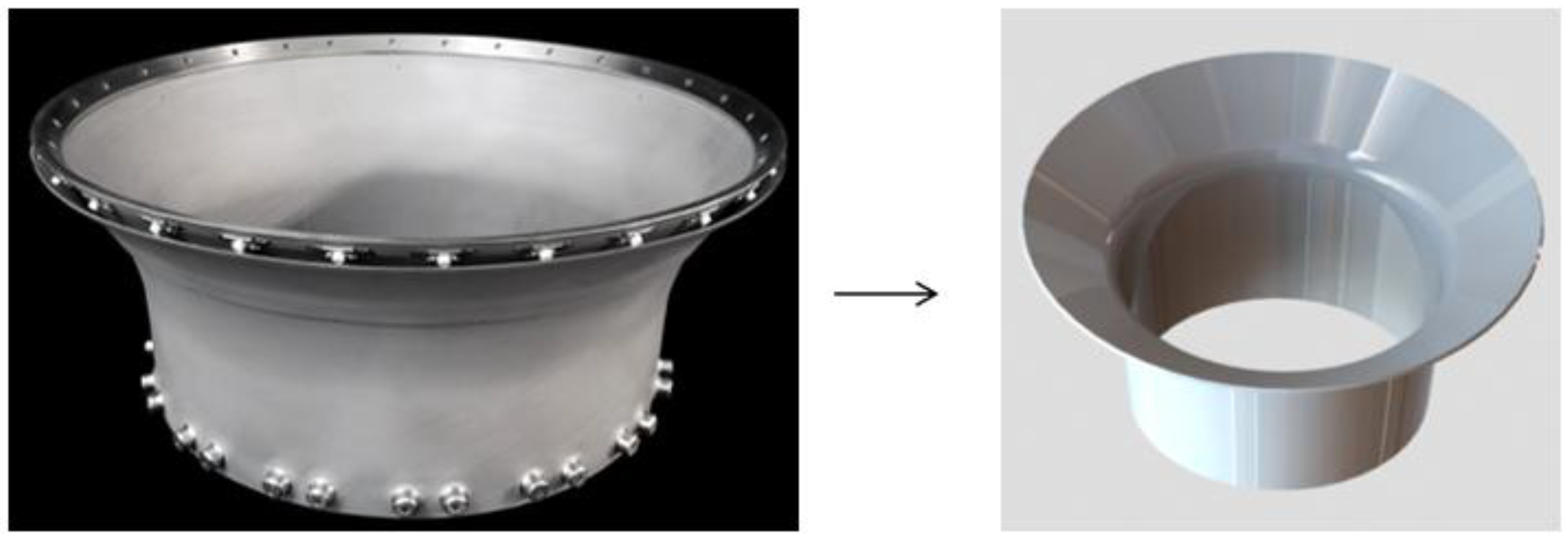
Figure 1 shows a simplified model of a combustion liner, formed by two straight segments and a transition arc. Stiffener design patterns along the tube wall are illustrated in
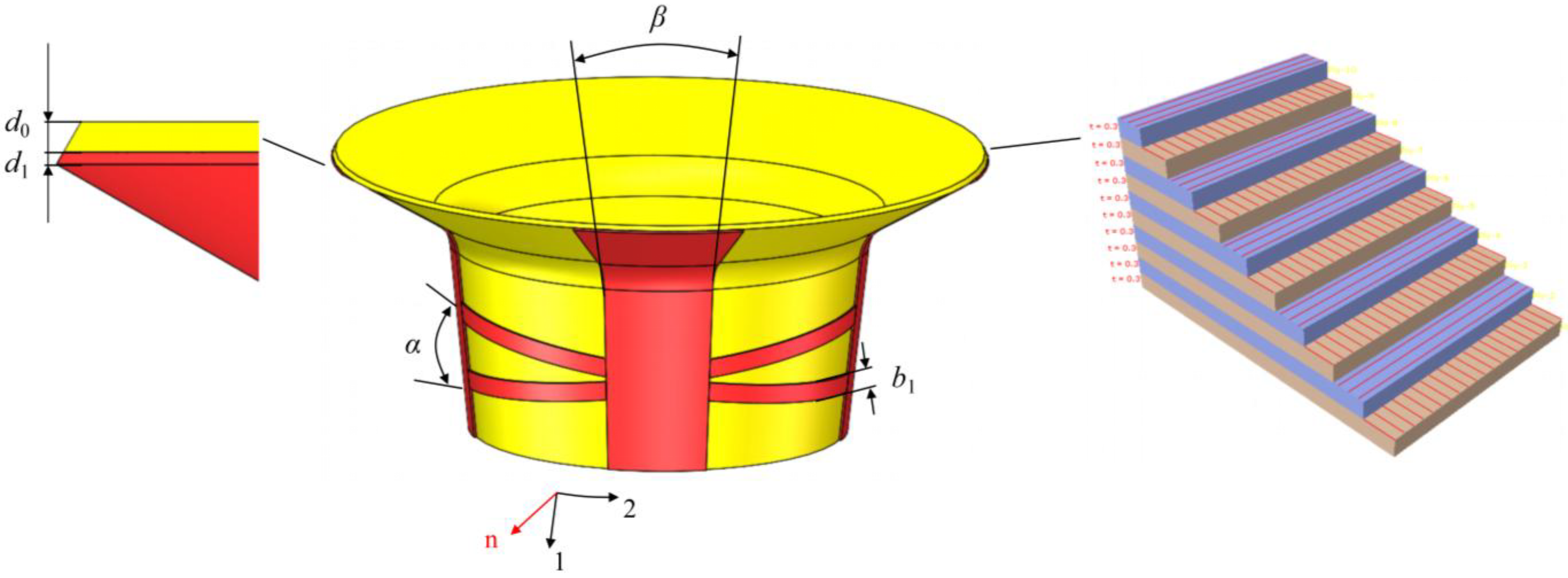
Figure 2, featuring longitudinal and transverse stiffeners. The longitudinal stiffeners span the entire axial direction, consisting of four groups evenly distributed at 90° intervals. Transverse stiffeners are exclusively arranged in the lower smooth section, forming two symmetrically positioned groups along the circumferential direction with adjustable angles relative to the horizontal plane.
The material of the combustion liner structure is set as ceramic matrix composite. The material properties of unidirectional ply are taken according to the data in literature [
25], measured from the material Prepreg HiPerComp™ (General Electric Company, Boston, MA, USA) of 8-ply laminates, with a balanced [0-90–90-0]s stacking of uniaxial plies, and nominally 22–25% by volume of Hi-Nicalon™ (Nippon Carbon Company, Tokyo, Japan) fibers. Here, the material data is used for informative purposes only, and not for engineering specifications. The fiber main direction is taken as 1, the vertical fiber direction in the lamination plane is taken as 2, and the normal direction in the lamination plane is taken as 3 (
Figure 3). The specific parameters are shown in
Table 1.
The design parameters selected include combustion liner basic wall thickness d
0, stiffener thickness
d1, transverse stiffener width
b1, transverse stiffener angle
α, longitudinal stiffener angle
β, and fiber layer scheme
M. All stiffener cross-sections are defined as rectangular. All stiffener structures are employed on the outer surface of the combustion liner, thus ensuring the heat/fluid boundary conditions of inner surface. A finite element model was established to conduct natural frequency simulation analysis, investigating how different stiffener configurations affect the fundamental frequency of the combustion liner. The schematic diagram of design parameters is shown in
Figure 4. The computational analysis in this work is fulfilled by commercial software ABAQUS (version 6.14), and the optimization procedure is implemented by the development of Python (version 2.7) scripts embedded in ABAQUS.
5. Conclusions
This study optimized reinforced configurations of CMC combustion liner structures to enhance natural frequencies. Using an orthogonal experimental design with six variables—wall thickness, stiffener thickness, transverse stiffener width and angle, longitudinal stiffener width, and lamination scheme—the analysis showed that wall thickness had the greatest influence, followed by stiffener thickness, lamination scheme, and transverse stiffener width. Notably, the 45° lamination scheme showed superior performance compared to other configurations in improving structural frequency. Multivariate linear regression analysis effectively characterized the frequency response through these six variables, explaining 97.4% of variation while demonstrating no multicollinearity or self-correlation issues, validating the model’s effectiveness. Under 1200 °C conditions, although the stiffener design achieved identical results as at 25 °C, reduced material stiffness at elevated temperatures led to decreased fundamental frequency. The regression model ultimately identified optimized stiffener parameters that significantly improved frequency performance while altering low-order modal order characteristics.
This study establishes a theoretical basis for optimizing composite combustion liner structures in aero-engines and provides practical guidance for similar designs. By tailoring stiffener configurations and lamination schemes, natural frequencies can be effectively increased, enhancing vibration resistance and extending service life. Future work will explore diverse stiffener geometries and layering strategies, with the goal of implementing and validating these designs in operational aero-engine systems.


