Article

Investigations of Edge Cutting Effects on Mechanical Behaviors of 3D Braided Composites with Different Braiding Angles

1
Nanjing Fiberglass Research & Design Institute Co., Ltd., Nangjing 210012, China
2
School of Textile Science and Engineering, Xi’an Polytechnic University, Xi’an 710048, China
3
North Long Dragon New Materials Technology Co., Ltd., Xi’an 710199, China
4
School of Textile Science and Engineering, Wuhan Textile University, Wuhan 430200, China
5
Shaanxi Yuanfeng Prosafe Co., Ltd., Xi’an 710038, China
*
Author to whom correspondence should be addressed.
J. Compos. Sci. 2025, 9(11), 573; https://doi.org/10.3390/jcs9110573 (registering DOI)
Submission received: 8 September 2025 / Revised: 16 October 2025 / Accepted: 21 October 2025 / Published: 24 October 2025
(This article belongs to the Topic Numerical Simulation of Composite Material Performance)

Abstract

Three-dimensional braided composites (3DBCs) exhibit broad application prospects in the aerospace field due to their excellent mechanical properties. Considering that composites require cutting processing during real applications, this study employs a combination of experimental and finite element analysis methods to investigate the influence of edge cutting on the compressive and flexural properties of 3DBCs. In the finite element model, full-scale mesostructural models with intact and edge-cut structures were constructed based on identical unit cell size parameters. The findings reveal that the effect of edge cutting on composite mechanical properties depends on the braiding angle, primarily because the deformation resistance of braided yarns varies with different braiding angles. However, the influence mechanisms of edge cutting on braided composites with large braiding angles differ between compressive and flexural loading modes. The results of this study can provide a reference for the practical application of 3DBCs.

1. Introduction

Three-dimensional braided composites (3DBCs) are a type of textile structural composite in which fibers are oriented and interlaced along four relative spatial directions. Owing to the tight interlacing of internal braided yarns and excellent anti-delamination performance, they are widely used in high-end fields such as aerospace, ordnance, and civil engineering [1,2,3,4]. However, during the service and application of braided composites, an important issue to consider is that edge trimming may cause varying degrees of loosening of the structure. The loosening of the braided structure may affect the integrity of the structure, thereby leading to changes in its performance. Therefore, studying the effect of edge trimming on the mechanical properties of braided composites is an important issue that needs to be considered in the engineering application of braided composites.
In recent years, fundamental research on 3DBCs has advanced extensively, covering intrinsic mechanical behaviors, failure mechanisms, effects of damage and defects, and multi-scale modeling with performance prediction. Li et al. [5] pioneered in situ tensile damage self-monitoring of 3DBCs using embedded sensors, while Qi et al. [6] elucidated how axial yarn architecture regulates the shape memory response of thermoset 3DBCs. Li et al. [7] systematically characterized modified aramid fiber-reinforced 3DBCs, reporting an 18% increase in interlaminar shear strength compared to pristine counterparts. Temperature-dependent investigations by Cui et al. [8], Yang et al. [9], and Zuo et al. [10,11] revealed that temperatures exceeding 150 °C reduce flexural modulus by 22–35% due to matrix softening. Li et al. [12,13], Du et al. [14], and Zhu et al. [15] dissected tensile and compressive failure mechanisms, identifying braided angle misalignment as a critical failure initiator. Fang et al. [16] quantified the Mode I fracture toughness (GIc = 450–680 J/m2) of 3DBCs with varying fiber volume fractions. Huang et al. [17] developed a mechanical model for tubular 3DBCs under combined loading. Zhang et al. [18] established a mathematical correlation between braiding structure complexity and elastic modulus anisotropy. Gao et al. [19,20] demonstrated experimentally that 5 mm diameter holes decrease tensile strength by 37%, with stress concentration factors peaking at hole edges. Huang et al. [21] and Zhang et al. [22] showed that void contents ≥3% lead to nonlinear degradation of compressive strength. Ge et al. [23,24] employed X-ray computed tomography (CT) to map void distributions in 3DBCs, confirming that void clustering induces localized shear band formation. Fu et al. [25] predicted the porosity of 3D braided composites from the microscale to the mesoscale. Guo et al. [26] noted that edge defects ≥ 2 mm in size trigger stress redistribution, resulting in premature delamination. Zhai et al. [27] proposed a micro-distortion quantification model, revealing that fiber misalignment angles >8° reduce fatigue life by 15%. Zhang et al. [28] reviewed homogenization-based models for predicting the elastic properties of 3DBCs. Wang et al. [29] identified “scale-bridging uncertainty” as the primary bottleneck limiting prediction accuracy in multi-scale frameworks. He et al. [30] developed a coupled meso–macro finite element model that accurately predicts failure evolution under mixed-mode loading, with a deviation of <5% from experimental data. Lomov et al. [31] revealed the law governing the influence of microstructures on macro-mechanical properties, and emphasized the critical role of accurate characterization of yarn orientation and interface bonding status in understanding damage initiation and propagation. Karahan et al. [32] explored the relationship between braiding parameters and mechanical anisotropy, and found that slight changes in yarn interlacing patterns significantly affect the tensile and compressive responses of the material. On the other hand, Karahan et al. [33] studied the flexural mechanical behavior of 3DBCs under different edge conditions, and pointed out that edge defects can cause stress concentration in the matrix and accelerate interface failure.
In summary, the above studies have laid a solid foundation for the application of 3DBCs in aerospace. However, research on the effect of edge trimming on the mechanical properties of 3DBCs remains limited. Li et al. [34] firstly investigated the effects of edge cut on the tensile, compressive and bending properties of 3DBCs through an experimental method. They found that cutting directions along the thickness or width also affected the axial properties differently. Wang et al. [35] combined experimental and numerical methods to study the influence of edge cut on the tensile strength of 3D five-directional braided composites (3D5DBCs). In addition, Zhang et al. [36] also reported a related investigation using the digital image correlation method. Based on the aforementioned studies, research about the effect of edge cutting on mechanical behaviors of 3DBCs is of great significance for their practical applications from an engineering perspective. However, the above research primarily adopted the representative unit cell method to study the edge-cut effects on the braided composites, which could not intuitively reveal the influence mechanism of the cut-edge region, and did not take into account the influence of the interface. Hence, the underlying mechanism governing such effects has not yet been systematically elucidated via the micro-structural model.
The objective of this study is to investigate the influence of cutting edge on the compressive and flexural properties of 3DBCs under different braiding angles. The research process is organized as follows. Firstly, specimens of 3DBCs with intact and edge-cut structures (for different braiding angles) were designed based on relevant formulas. Secondly, the variation laws of their compressive and flexural properties were explored through experiments and numerical calculations. Then, the failure processes obtained from numerical results were discussed in detail to reveal the mechanism of cutting-edge effects affecting the compressive and flexural properties of 3DBCs. Finally, some critical findings of this work were concluded.

2. Experimental and Numerical Details

2.1. Experimental Details

This work employed a full-factorial experimental design, where three parallel specimens were tested for each combination of three braiding angles (10°, 15°, 27°), two specimen states (intact vs. edge-cut), and two loading modes (compression vs. bending). This approach enables precise capture of the effects of individual variables and their interactions. The selection of braiding angles (10–27°) comprehensively considers both practical engineering requirements and the intrinsic mechanical properties of the material. The choice of loading modes is based on the dominant compression and bending loads in aerospace load-bearing components, balanced with the need for research depth.
Figure 1 presents the preparation of 3D braided composite specimens designed to investigate the edge-cutting effect on the mechanical behaviors of 3DBCs. The 3D braided preforms were fabricated using the 1 × 1 four-step 3D braiding technique, with T700S-12K carbon fibers supplied by Weihai Tuozhan Composites Co., Ltd, Weihai, China. The fiber volume fraction of all specimens was controlled at approximately 50% by the metal mold and calculated through the weight method [37]. The transverse cross-sectional dimensions of the test specimens in this study were 10 × 4 mm2. The selection of this dimension was made after comprehensively considering standard testing specifications, the feasibility of composite manufacturing, and experimental efficiency. Figure 1a shows the 3D braided preform with an intact structure (without edge cutting) at different braiding angles (10°, 15°, 27°), featuring a basic braiding array of 9 × 3. The JC-02A epoxy resin mixed with modified anhydride (JC-02B) provided by Changshu Jiafa Chemical Inc, Changshu, China. was adopted as the matrix material. The 3DBCs were cured through the vacuum-assisted resin transfer molding (VARTM) process, with the curing process as follows: 90 °C for 2 h, 110 °C for 1 h and 135 °C for 6 h. When the 3DBCs were cured via the VARTM process, their void content was first verified to meet the requirements using a combination of qualitative assessment and quantitative calculation. Subsequently, the composites were cut to the specified length along the longitudinal direction. Figure 1c clearly illustrates the intact structural schematic of the preform with uncut edges. It can be observed that the uncut composite features an intact corner yarn structure with continuous braiding yarns. Figure 1b depicts the method for preparing edge-cut composite specimens by cutting large-sized samples to the same cross-sectional dimension (10 × 4 mm2) as the uncut braided composites. Figure 1d provides the structural schematic of the braided preform with a cut edge. As shown in Figure 1d, the surface yarns from the left or right sides and the four corner yarns of braided composites were primarily cut off. Due to cutting the side surface and corner yarns, the braiding yarns are no longer continuous, which may result in changes in the mechanical properties of braided composites.
This work primarily investigates the influence of edge cutting on the in-plane compressive and three-point bending mechanical properties of 3DBCs. Figure 1e–g briefly present the experimental diagrams of compressive and bending loading. The relevant mechanical property tests refer to ASTM D6641 [38] (for compressive properties) and ASTM D7264 [39] (for flexural properties). To guarantee the statistical reliability of the experimental results, 3 replicate tests were conducted for each specimen. The interference of random errors on the results was thus effectively reduced through multiple repeated tests. The dimensions of the specimens for compressive and bending tests are 10 × 10 × 4 mm3 and 50 × 10 × 4 mm3, respectively. For the three-point bending test, the span is 32 mm.

2.2. Numerical Details

The finite element method enables intuitive comparison of the influence of geometric structural differences on the mechanical properties of composites. In this work, the full-scale mesostructural finite element model based on the actual experimental structure is employed to analyze the effect of edge cutting on the compressive and bending mechanical properties of 3DBCs. The models were solved via a dynamic explicit algorithm to ensure stable results for all loading conditions and models.
Figure 2 shows the primary details of creating the full-size finite element model for the intact and edge-cut models. As illustrated in Figure 2a, the finite element models for intact and edge-cut specimens of 3DBCs under in-plane compression are presented. The key model of the 3DBC was to create the geometrical model of the braided preform according to the detailed geometrical parameters in the experiment. The geometrical model of the resin matrix was obtained through Boolean logic operations based on the geometrical model of the braided preform. Both models have identical basic unit cell dimensions, with the primary distinction being that the edge-cut model is derived by sectioning from a large-sized model. In the models, the upper and lower platens are defined as rigid bodies and controlled through the displacement boundary conditions to simulate compression deformation. For both models, carbon fibers and resin are assumed to be elastoplastic materials, with failure of the composites governed by ductile and shear failure criteria. The fiber–resin interface is modeled using a surface-based cohesive behavior model. Hard contact is defined for the contact surfaces between the platens and the composite. The main mechanical parameters of braided yarns, resin, and interfaces in this work are listed in Table 1, primarily referring to previous work [40,41,42].
Figure 2b shows the meshing method for both intact and edge-cut models. Due to the presence of more irregular geometric features inherent in the edge-cut model, 3D four-node tetrahedral elements (C3D4) are employed to mesh the reinforcement and resin matrix, with a global seed size of 0.3 mm. The C3D4 elements can fully accommodate the irregular sharp tips formed in the yarn model after the edge cutting process. According to the previous work [42], a mesh size of 0.3 mm not only meets the accuracy requirements for mechanical analysis of composites but also improves computational efficiency. Figure 2c presents the bending finite element models for the intact and edge-cut specimens. Because the modeling approach and fundamental material parameters are consistent with those of the compression models, detailed elaboration is omitted herein. Additionally, all models shown in Figure 2 correspond to 3DBCs with a braiding angle of 27°. The modeling method for specimens with a 10° braiding angle is identical and thus not redundantly described.

3. Results and Discussions

3.1. Compressive Results

3.1.1. Comparisons of Stress–Strain Curves

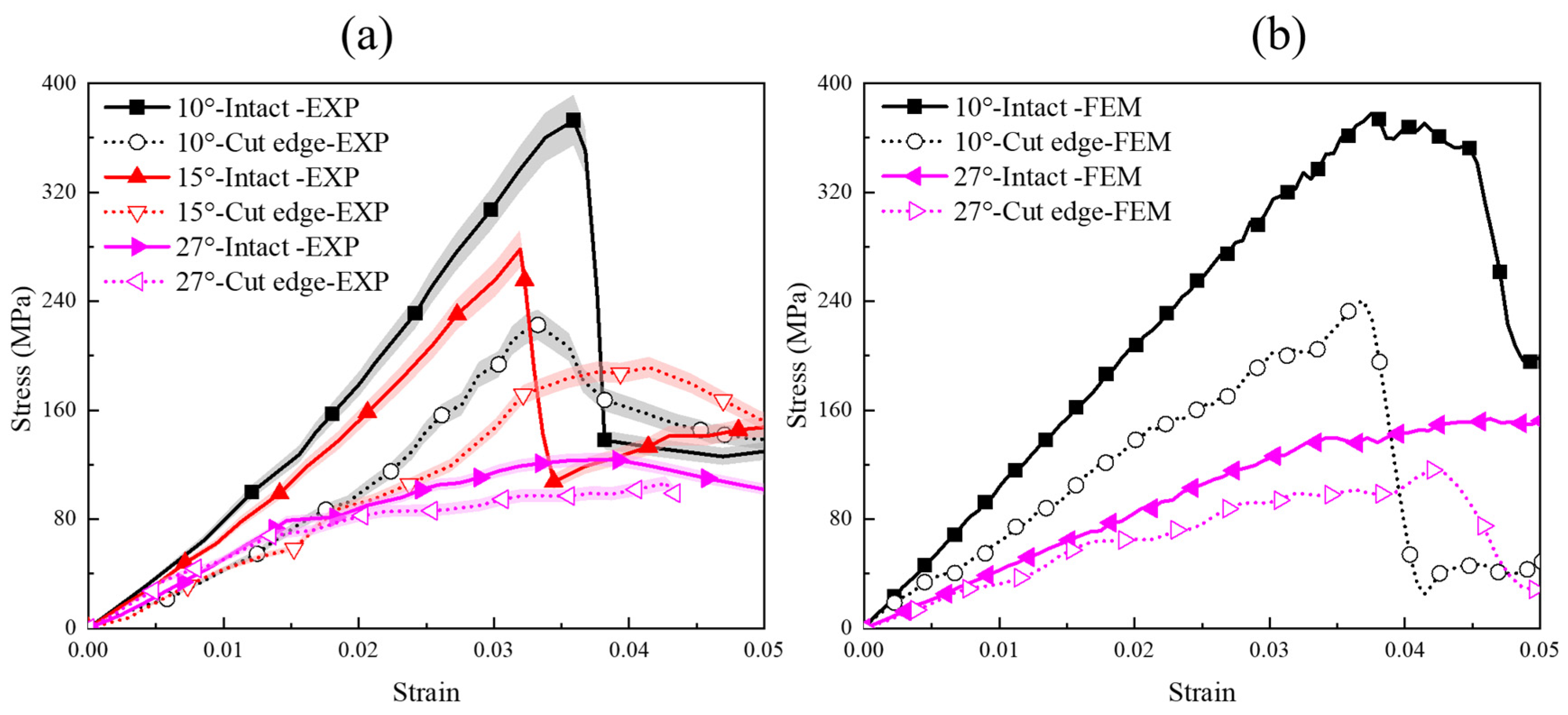
Figure 3a,b present the experimental and finite element results of compressive stress–strain curves for uncut and edge-cut specimens of 3DBCs, respectively. The finite element simulations only include results for composites with braiding angles of 10° and 27°, as the primary purpose of the finite element analysis is to reveal the mechanism of edge cutting affecting the mechanical behaviors of 3DBCs.
As evident from the experimental stress–strain curves in Figure 3a, the compressive stress–strain behavior of 3DBCs is strongly dependent on the braiding angle. For intact specimens, the stress–strain curves exhibit distinct brittle characteristics at braiding angles of 10° and 15°. This is attributed to the higher straightness of braided yarns along with the loading direction at smaller braiding angles, which enhances the strength utilization efficiency of the yarns. When the braiding angle is 27°, the stress–strain curve changes significantly. For example, both the strength and modulus decrease remarkably. In addition, the curve declines gradually after reaching the peak stress, indicating obvious ductile failure. This phenomenon was because braided yarns in the composites with larger braiding angles are more inclined relative to the loading direction, resulting in lower utilization efficiency. Hence, 3DBCs primarily undergo large deformation due to fiber inclination, accompanied by failure of the resin and fiber–resin interface.
For edge-cut 3DBCs, the stress–strain curves in Figure 3a still exhibit a decreasing trend with the rise in braiding angle. However, with a 10° braiding angle, the compressive strength drops from 372 MPa to 222 MPa. The standard deviations of the intact and edge-cut samples were 11.67 MPa and 6.42 MPa, respectively, indicating stable experimental data. The strength reduction rate reaches about 40.3%. This significant decline indicates that edge cutting exerts a substantial influence on the compressive performance of 3DBCs along with the in-plane direction. With increasing braiding angles, edge cutting caused the compressive strength of composites with 15° and 27° braiding angles to decrease by 31.3% and 19.4%, respectively. Although the decreasing trend gradually flattens, the influence remains noticeable. A similar trend is observed in the finite element stress–strain curves shown in Figure 3b. Experimental and numerical stress–strain curves can only analyze the trend of performance degradation caused by the edge cutting process. The stress–strain curves are insufficient to illustrate the specific microscopic mechanisms underlying the influence of the edge cutting process.

3.1.2. Comparisons of Stress Contours in the Numerical Results

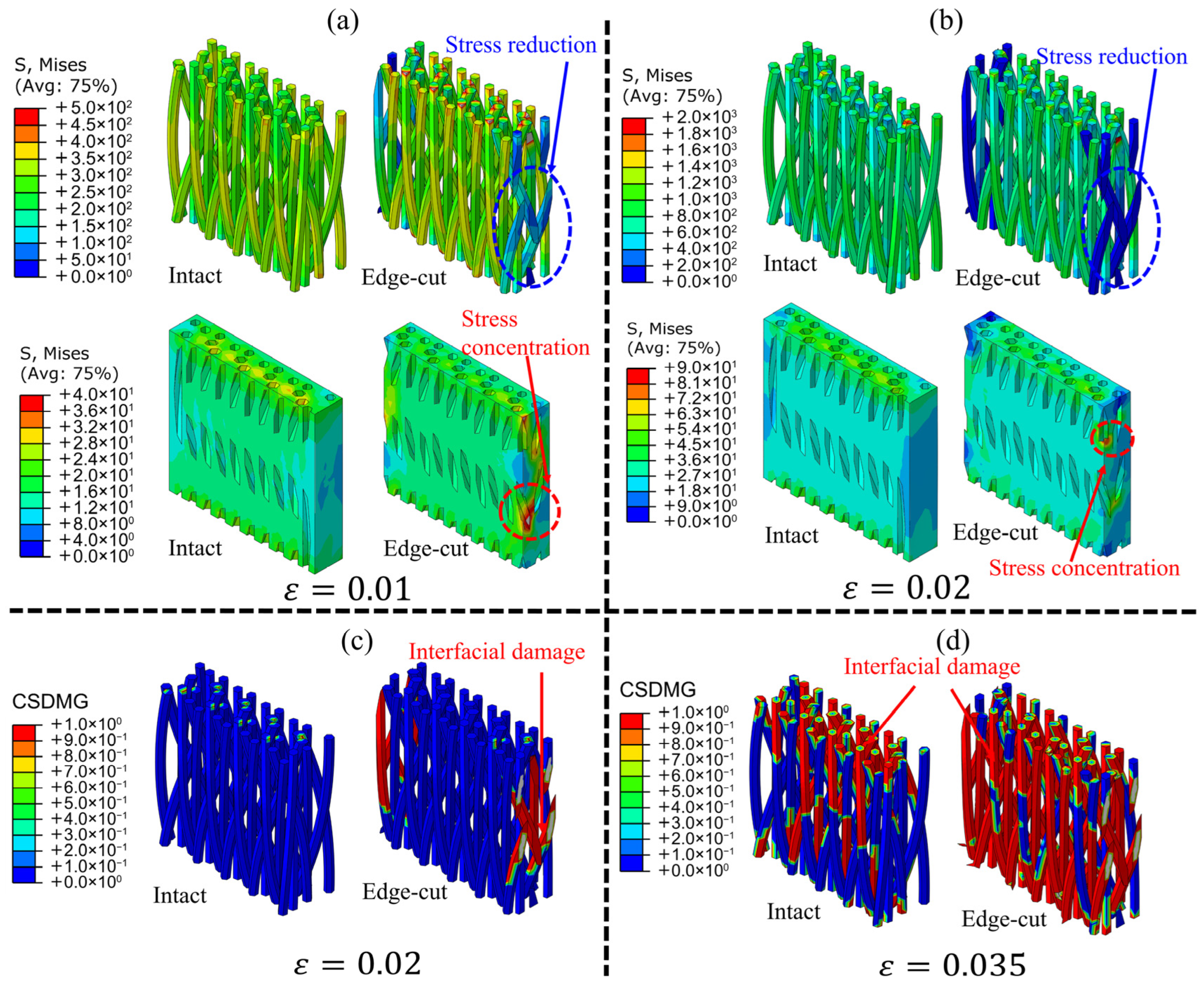
Figure 4 plots the contour of stress distribution and failure status for the braided reinforcement and matrix (Figure 4a,b), and interface (Figure 4c,d), of 3DBCs with a 10° braiding angle under in-plane compression loading. As shown in Figure 4a, the composites exhibit no obvious failure but undergo significant compressive deformation when the strain reaches 0.01. At this stage, the stress distribution patterns on braided yarns and matrix are consistent between intact and edge-cut specimen models. For instance, the reinforcement bears the majority of the stress yet the resin matrix undergoes lower stress. However, in edge-cut specimens, the color gradient of stress distribution indicates lower stress in the side yarns, suggesting that these yarns carry less stress. This phenomenon arises because the side yarns are discontinuous and located at free edges, lacking constraints from adjacent braided yarns and matrix, which impairs their ability to effectively transfer stress. Consequently, the resin matrix in corresponding regions must bear more stress. Because the finite element model employs displacement boundary conditions, the average stress across the loaded section should be equal to ensure equilibrium of the material and model.
When the 3DBCs are further compressed, Figure 4b also shows a similar stress distribution trend to Figure 4a. Nevertheless, the stress in the side yarns of the edge-cut model remains low with increasing strain. This is because the interface in the same region undergoes failure simultaneously while the resin in this region bears high stress, as illustrated in Figure 4c. The indicator CSDMG in Figure 4c represents the status variable describing whether the interface undergoes failure or not. From Figure 4c, it can be observed that interface failure occurs earlier in edge-cut composites compared to uncut ones. Figure 4d further demonstrates the propagation of interface failure in braided composites. It is evident that both edge-cut and intact models eventually fail due to extensive interface failure.
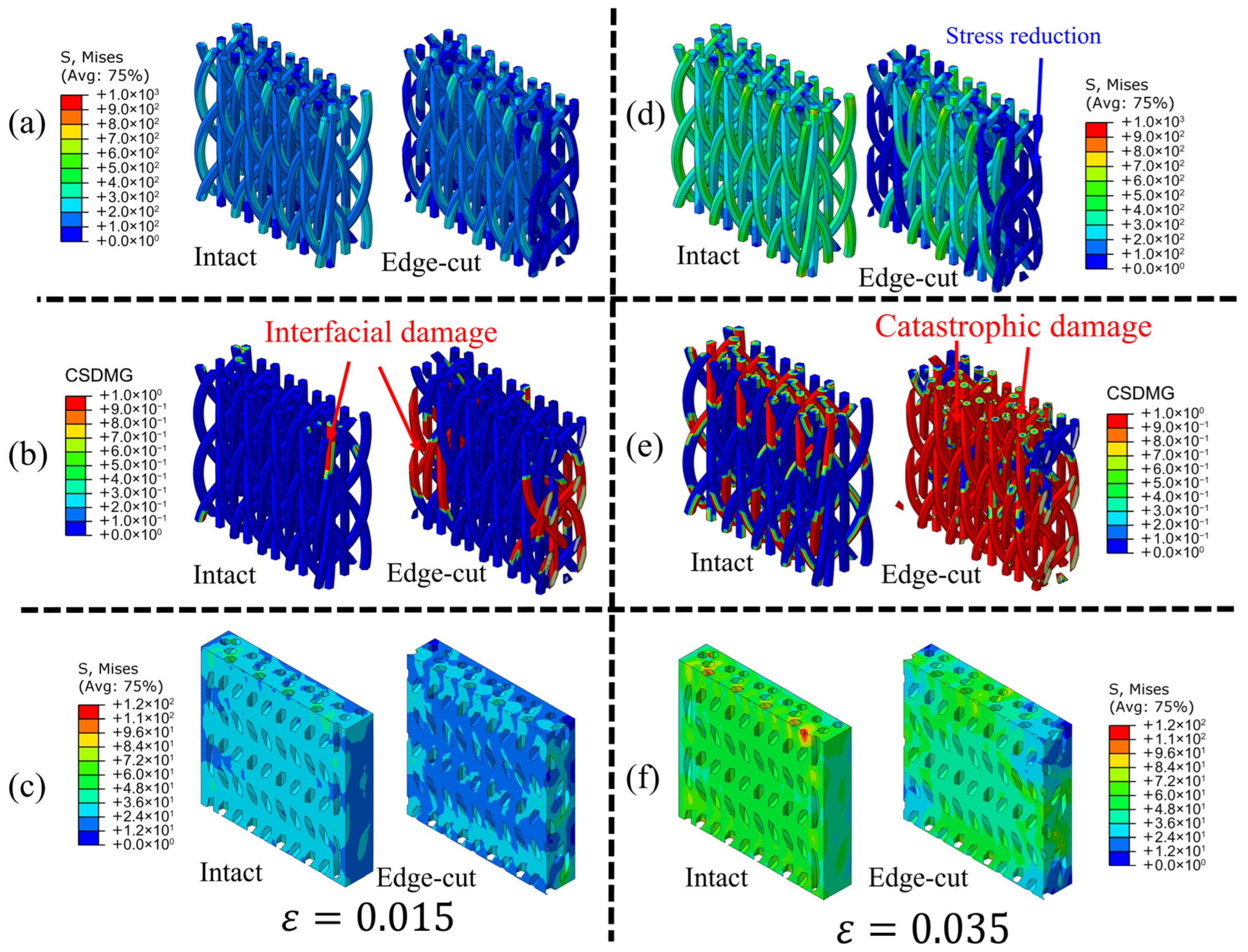
Figure 5 further presents the stress distribution contours of each component in intact and edge-cut specimens of braided composites with a 27° braiding angle. As shown in Figure 5, the stress characteristics of braided composites with a 27° braiding angle differ from those of composites with a 10° braiding angle. For instance, in braided composites with a 27° braiding angle, the stress of braided yarns in the edge-cut model at the boundary remains lower than that in other regions. However, the stress difference is less obvious than in braided composites with a 10° braiding angle. This is because braided yarns with larger braiding angles have a greater inclination, making them less effective at resisting compressive deformation. This weak ability of braided yarns to resist compressive deformation causes the resin matrix and interface in composites with the large braided angle to bear higher stress. For example, localized interface failure is observed in Figure 5b, and the resin matrix in Figure 5c bears high stresses. However, the distribution of interface failure in Figure 5b varies significantly when the compressive strain is 0.015. Figure 5b shows that the interface failure in intact composites is minimal, while edge-cut composites exhibit a larger area of interface failure. This extensive interface failure is the primary reason for the lower compressive performance of edge-cut composites. With further compression, braided yarns gradually exhibit higher stress under large compressive deformation (strain reaching 0.035), whereas the stress of yarns in the edge-cut model remains low. It indicates that discontinuous braided yarns after edge cutting still cannot effectively resist deformation at large braiding angles. Additionally, the stress values of braided yarns confirm that they are far from failure. Thus, the failure of braided composites is mainly caused by interface damage as shown in Figure 5e. Furthermore, there is a significant difference in interface failure between intact and edge-cut composite models. Figure 5e shows that the interface failure area of intact composites is smaller than that of edge-cut composites. As seen in Figure 5f, the resin stress distribution in both braided composites is similar at this stage. This is because the deformation and load-bearing ability are primarily governed by the matrix in the braided composites with a large braiding angle, since the interface failure disrupts stress transfer between fibers and resin.

3.2. Three-Point Bending Results

3.2.1. Variations of Stress–Strain Curves

Figure 6 presents the experimental and finite element simulated flexural stress–strain curves of intact and edge-cut braided composites under three-point bending loading. The experimental curves in Figure 6a show that 3DBCs with a 10° braiding angle exhibit the highest bending strength (1193 MPa) and modulus (69.5 GPa), with a standard deviation of 22.46 MPa and 1.40 GPa, respectively. However, as the braiding angle increases, both parameters decrease significantly to 445 MPa and 38.9 GPa when the braiding angle reaches 27°, with a standard deviation of 13.94 MPa and 1.17 GPa, respectively. This decline arises because the ability to resist bending deformation under three-point bending primarily depends on the straightness of braided yarns in the compressed and tensile surfaces. Smaller braiding angles correspond to higher fiber straightness, enabling composites to resist bending deformation effectively. Conversely, larger braiding angles reduce fiber straightness, weakening the ability to resist bending and thus lowering strength and modulus. Additionally, Figure 6a reveals differences between the stress–strain curves of intact and edge-cut composites. For edge-cut composites, the bending strengths of composites with 10° and 27° braiding angles are 1060 MPa and 376 MPa, with moduli of 61.2 GPa and 33.8 GPa, respectively. The influence of edge cutting on flexural performance is affected by the braiding angle. A similar trend was also reflected in numerical results as shown in Figure 6b. Different from the compressive results, the decline rates of flexural strength of 3DBCs caused by the edge cutting process are only about 11.1% and 15.5%. The mechanism of the edge-cut effect will be revealed in the next section through analyzing the stress distribution of different components in braided composites by finite element models.

3.2.2. Variations of Stress Contours in the Numerical Results

Figure 7 presents the stress distribution contours of braided preforms in 3DBCs under different strains. As shown, braided yarns of composites with various braiding angles all experience high stress near the indenter on the compressed surface under the flexural loading process. However, the stress color and distribution range of braided yarns with a 10° braiding angle indicate that composites with smaller braiding angles bear greater applied stress at the same strain. This is because the resistance to bending deformation primarily depends on the compressive capacity of the compressed surface and the tensile capacity of the tensile surface of the specimen. Thus, the influence of braiding angle on the bending behavior of 3DBCs is consistent with its influence on compressive behavior. On the other hand, a comparison of stress distributions between intact and edge-cut braided preforms reveals that braided yarns at the cut edge still exhibit lower stress values, while the stress distribution patterns in other regions of the two models are essentially identical. There are different reasons that explain the phenomena of braided composites with various braiding angles.
Figure 8 further analyzes the stress distribution and failure process of the resin under different strains. As shown, the main stress of the resin remains distributed in the compressed surface region near the indenter. Furthermore, a larger area of the resin matrix bears more stress in composites with larger braiding angles unlike the yarn stress distribution in Figure 7. Meanwhile, a comparison of stress distributions in the resin matrix between intact and edge-cut composites reveals localized stress concentration near the cut edge in edge-cut composites. The primary reason for these two phenomena is that the bending load borne by braided yarns is not effectively transferred to the corresponding resin matrix regions. With further increases in bending strain, the regions in the resin with a significant initial stress concentration eventually undergo failure. Figure 8 also illustrates the interface failure between braided yarns and the resin matrix during the bending process. At a strain of 0.01, the CSMAXSCRT distribution in the 10° braided composite model shows that edge-cut composites have already developed localized interface failure at the boundary area. In contrast, the CSMAXSCRT distribution in the 27° braided model indicates that the yarn interface distributions of intact and uncut composites are essentially identical. The difference in interface distribution between the two braiding angle models further confirms that the edge-cut effect has a more significant impact on composites with smaller braiding angles.
When the strain reaches 0.024, the CSDMG distribution shows significant interface failure in both intact and edge-cut braided composites with a 10° braiding angle. The key distinction is that interface failure in intact composites occurs across the entire compressed surface, whereas interface failure in edge-cut composites is mainly concentrated near the cut edge. Thus, the difference in interface failure is the primary cause of the bending performance variation in edge-cut composites with small braiding angles. However, in the models with a 27° braiding angle, both intact and edge-cut composites exhibit extensive and complex interface failure in the compressed surface region when the strain is 0.015. This failure is primarily due to the reduced ability of braided yarns to resist bending deformation in large-braiding-angle composites, with the final failure dominated by resin damage. From the resin perspective, edge cutting has little impact on the resin, resulting in relatively small differences in composite failure. Therefore, the minor reduction in bending performance of edge-cut braided composites with a 27° braiding angle in Figure 7 is attributed to the discontinuity of braided yarns in the edge-cut model.

4. Conclusions

This work focuses on the influence of edge cutting on the compressive and flexural mechanical behaviors of 3D four-directional braided composites. Experimental results are primarily used to analyze the effect of edge cutting on basic mechanical properties, while finite element models are employed to reveal the underlying mechanism via stress distribution nephograms. The findings indicate that edge cutting exerts varying degrees of influence on the compressive and flexural properties of 3DBCs. Specifically, edge cutting has the most significant impact on the compressive properties of composites with a small braiding angle, mainly attributed to yarn discontinuity induced by cutting, leading to earlier interface failure in edge-cut composites. When the braiding angle is 10°, the strength decreases by 40.3%. However, this decrease gradually weakens to 19.4% when the braiding angle is increased to 27°, as the role of braided yarns in resisting deformation diminishes. In the analysis of flexural results, the influence of edge cutting shows a moderate decreasing trend. The decrease rate of flexural strengths in 10° and 27° 3DBCs reaches 11.1% and 15.5%, respectively. The primary difference compared with the compressive behaviors was that yarn discontinuity only reduces the yarn’s own deformation resistance without causing premature failure of the resin or interface in edge-cut composites.
Overall, edge cutting does impact the mechanical behaviors of 3DBCs to a certain extent. If an edge cutting process is required for final products in engineering applications, it is feasible provided that the reduction rate of mechanical properties in 3DBCs caused by cutting is accurately predicted. This study focuses on the effect of edge cutting on the compressive and flexural properties of 3DBCs, but does not cover the law of edge cutting under other loading conditions. Future research plans include expanding to typical loading modes such as tension and shear to provide more complete theoretical support for the engineering application and performance optimization of such materials.

Author Contributions

Conceptualization, Y.B., Y.C. and T.L.; methodology, Y.O.; software, R.Z. and J.D.; validation, Z.Z., R.Z.,Y.O. and J.D.; formal analysis, Y.B., Z.Z., H.Z. and R.Z.; investigation, Y.B., Z.Z., Z.W. and H.Z.; resources, H.Z. and Y.C.; data curation, Z.W., Y.O. and J.D.; writing—original draft preparation, Y.B.; writing—review and editing, T.L., Y.C. and J.D.; visualization, Z.W., H.Z. and R.Z.; supervision, T.L.; funding acquisition, T.L. and Y.C. All authors have read and agreed to the published version of the manuscript.

Funding

This research was funded by the National Natural Science Foundation, China (grant number: 12002248), and the Qin Chuangyuan Scientist + Engineer Project in Shaanxi Province (grant number: 2023KXJ-005).

Data Availability Statement

The original contributions presented in this study are included in the article. Further inquiries can be directed to the corresponding author.

Conflicts of Interest

Authors Yafei Bai and Zhen Zhang were employed by the company Nanjing Fiberglass Research & Design Institute Co., Ltd., Author Yue Chen was employed by the company North Long Dragon New Materials Technology Co., Ltd., and Author Jingjing Dong was employed by the company Shaanxi Yuanfeng Prosafe Co., Ltd. The remaining authors declare that the research was conducted in the absence of any commercial or financial relationships that could be construed as a potential conflict of interest.

References

  1. Xie, Y.N.; Quan, Z.Z.; Ren, W.; Qin, X.H.; Yu, J.Y. Multifunctional 3D Carbon Fiber/Epoxy Braided Composites with Excellent Compression Performance and Electromagnetic Interference Shielding. Mater. Lett. 2024, 372, 137036. [Google Scholar] [CrossRef]
  2. Jiang, L.L.; Li, Z.G.; Wang, D.Y.; Zhai, J.J.; Kong, X.X. Theoretical Analysis of Thermophysical Properties of 3D Carbon/Epoxy Braided Composites with Varying Temperature. Polymers 2024, 16, 1166. [Google Scholar] [CrossRef]
  3. Yan, H.; Xu, X.Y.; Fu, B.; Fan, X.; Kan, Y.; Yao, X.F. Constitutive Model and Damage of Self-Healing 3D Braided Composites with Microcapsules. Compos. Commun. 2023, 40, 101586. [Google Scholar] [CrossRef]
  4. Liu, S.K.; Wang, L.Y.; Siddique, A.; Umair, M.; Shi, C.Y.; Pei, X.Y.; Liu, S.Q.; Yin, Y.; Shi, H.T.; Xu, Z.W. Irradiation Multi-Scale Damage and Interface Effects of 3D Braided Carbon Fiber/Epoxy Composites Subjected to High Dose γ-Rays. Compos. Part B Eng. 2024, 281, 111575. [Google Scholar] [CrossRef]
  5. Li, G.; Wu, T.W.; Xue, Y.S.; Li, Z.Y.; Sun, B.Z.; Gu, B.H. Tensile Damage Self-Monitoring of Carbon Fiber/Epoxy 3D Braided Composites with Electrical Resistance Method. Eng. Fract. Mech. 2024, 296, 109870. [Google Scholar] [CrossRef]
  6. Qi, Y.Y.; Huang, S.W.; Zhang, H.X.; Gu, B.H.; Sun, B.Z.; Zhang, W. Shape Memory Behaviors of Three-Dimensional Five-Directional Braided Composites with Different Axial Yarns Arrangements. Compos. Struct. 2024, 338, 118105. [Google Scholar] [CrossRef]
  7. Li, C.Y.; Shi, M.X.; Xing, W.J.; Song, J.J.; Shan, J.T.; Zhang, L.; Feng, C.H. Mechanical Properties of Modified Aramid Three-Dimensional Braided Composites. Polym. Adv. Technol. 2024, 35, e6197. [Google Scholar] [CrossRef]
  8. Cui, J.K.; Li, D.S.; Jiang, L. Comparison Study on Bending Properties and Failure of 3D5d and 3D6d Carbon/Phenolic Braided Composites at Room and Elevated Temperatures. Compos. Commun. 2023, 42, 101676. [Google Scholar] [CrossRef]
  9. Yang, X.; Li, D.S.; Jiang, L. Liquid Nitrogen Temperature Effects on the Mechanical Behaviors of Three-Dimensional Seven-Directional Braided Composites. Mater. Lett. 2023, 349, 134786. [Google Scholar] [CrossRef]
  10. Zuo, H.M.; Li, D.S.; Jiang, L. Transverse Bending Fatigue Behaviors and Failure Mechanisms of 3D Five-Directional Braided Composites at Different Temperatures. Mater. Lett. 2022, 316, 132030. [Google Scholar] [CrossRef]
  11. Zuo, H.M.; Li, D.S.; Jiang, L.; Fang, D.N. Longitudinal Compression Fatigue Properties of 3D Five-Directional Braided Composites at Different Temperatures. Compos. Struct. 2022, 291, 115602. [Google Scholar] [CrossRef]
  12. Li, A.; Qiao, K.; Curiel-Sosa, J.L.; Zhang, C. Numerical Study on Off-Axis Tensile Behavior of 3D Braided Composites at Elevated Temperature. Mech. Adv. Mater. Struct. 2024, 31, 1717–1730. [Google Scholar] [CrossRef]
  13. Li, Z.J.; Dai, H.L.; Liu, Z.G.; Wang, Y. Micro-CT Based Parametric Modeling and Damage Analysis of Three-Dimensional Rotary-Five-Directional Braided Composites under Tensile Load. Compos. Struct. 2023, 309, 116734. [Google Scholar] [CrossRef]
  14. Du, X.B.; Li, D.S.; Jiang, L.; Fang, D.N. Numerical Investigation on Tensile Behavior of Three-Dimensional Six-Directional Braided Composites. Int. J. Mech. Sci. 2023, 237, 107815. [Google Scholar] [CrossRef]
  15. Zhu, H.; Du, X.B.; Li, D.S.; Jiang, L. Investigation of Parameterized Braiding Parameters and Loading Directions on Compressive Behavior and Failure Mechanism of 3D Four-Directional Braided Composites. Compos. Struct. 2022, 287, 115357. [Google Scholar] [CrossRef]
  16. Fang, J.; Zhang, J.J.; Sun, B.Z.; Gu, B.H. Mode I Fracture Mechanisms and Crack Evolution Behavior of Three-Dimensional Braided Composites. Text. Res. J. 2023, 93, 4023–4034. [Google Scholar] [CrossRef]
  17. Huang, Z.H.; Ma, W.S.; Xu, W.T.; Mao, F.; Chen, C.; Zhao, J.N.; Xu, Y.H. The Formation Mechanism of Gradient Properties and the Regulation Mechanism of Elastic Properties in Three-Dimensional Tubular Braided Composites. Polym. Compos. 2024, 45, 16574–16588. [Google Scholar] [CrossRef]
  18. Zhang, D.; Zheng, X.T.; Zhou, J.; Song, X.Y.; Jia, P.; Liu, H.B.; Liu, X.C. Effect of Braiding Architectures on the Mechanical and Failure Behavior of 3D Braided Composites: Experimental Investigation. Polymers 2022, 14, 1916. [Google Scholar] [CrossRef]
  19. Gao, C.T.; Dai, W.J.; Gu, J.P.; Zeng, H.; Sun, H.Y. Mechanical Properties of 3D 4-Directional Braided Composites with a Central Circular Hole under Tension. Mech. Adv. Mater. Struct. 2024, 31, 5856–5868. [Google Scholar] [CrossRef]
  20. Gao, C.T.; Gu, J.P.; Zeng, H.; Khatibi, A.A.; Sun, H.Y. Prediction of the Stress Distributions and Strength Properties of 3-D Braided Composites with an Eccentric Circular Hole. Mech. Mater. 2023, 185, 104776. [Google Scholar] [CrossRef]
  21. Huang, H.; Guo, Z.T.; Shan, Z.D.; Sun, Z.; Liu, J.H.; Wang, D.; Wang, W.; Liu, J.L.; Tan, C.C. Prediction of Elastic Properties of 3D4D Rotary Braided Composites with Voids Using Multi-Scale Finite Element and Surrogate Models. Compos. Struct. 2024, 328, 117579. [Google Scholar] [CrossRef]
  22. Zhang, Y.Y.; Li, H.M.; Liu, X.; Gao, Y.H.; Guan, C.Y. Trans-Scale Elastic–Plastic Damage Analysis of 3D Tubular Braided Composites with Void Defects. Int. J. Solids Struct. 2023, 274, 112288. [Google Scholar] [CrossRef]
  23. Ge, L.; Li, H.M.; Gao, Y.H.; Lou, R.S.; Liu, K.; Zhong, J.H.; Fang, D.N. Parametric Analyses on Multiscale Elastic Behavior of 3D Braided Composites with Pore Defects. Compos. Struct. 2022, 287, 115332. [Google Scholar] [CrossRef]
  24. Ge, L.; Li, H.M.; Zhong, J.H.; Zhang, C.; Fang, D.N. Micro-CT Based Trans-Scale Damage Analysis of 3D Braided Composites with Pore Defects. Compos. Sci. Technol. 2021, 211, 108830. [Google Scholar] [CrossRef]
  25. Fu, Y.T.; Yao, X.F.; Gao, X.H. Micro-Mesoscopic Prediction of Void Defect in 3D Braided Composites. Compos. Part A Appl. Sci. Manuf. 2021, 147, 106450. [Google Scholar] [CrossRef]
  26. Guo, J.H.; Ke, Y.N.; Wu, Y.Y.; Gu, B.H.; Sun, B.Z. Effects of Defect Sizes at Different Locations on Compressive Behaviors of 3D Braided Composites. Thin-Walled Struct. 2022, 179, 109563. [Google Scholar] [CrossRef]
  27. Zhai, J.J.; Kong, X.X.; Wang, L.C.; Yan, S.; Jiang, L.L.; Cai, Z.W. Nonlinear Mechanical Property of 3D Braided Composites with Multi-Types Micro-Distortion: A Quantitative Evaluation. Polymers 2023, 15, 1428. [Google Scholar] [CrossRef] [PubMed]
  28. Zhang, N.; Kong, X.X.; Zhai, J.J.; Guo, Z.T.; Yan, S.; Duan, Y.K.; Zheng, Z.J. Advances in Multiscale Modeling and Mechanical Properties Characterization of 3D-Braided Composites. Adv. Eng. Mater. 2024, 26, 2401457. [Google Scholar] [CrossRef]
  29. Wang, Z.; Liu, S.; Zhao, Z.; Liu, F.; Zhang, H.; Shen, M. Key Issues in Microstructure Modeling of 3D Braided Composites. Mater. Res. Express 2023, 10, 036302. [Google Scholar] [CrossRef]
  30. He, C.W.; Ge, J.R.; Lian, Y.P.; Geng, L.C.; Chen, Y.F.; Fang, D.N. A Concurrent Three-Scale Scheme FE-SCA2 for the Nonlinear Mechanical Behavior of Braided Composites. Comput. Methods Appl. Mech. Eng. 2022, 393, 114827. [Google Scholar] [CrossRef]
  31. Lomov, S.V.; Bogdanovich, A.E.; Ivanov, D.S.; Mungalov, D.; Karahan, M.; Verpoest, I. A Comparative Study of Tensile Properties of Non-Crimp 3D Orthogonal Weave and Multi-Layer Plain Weave E-Glass Composites. Part 1: Materials, Methods and Principal Results. Compos. Part A Appl. Sci. Manuf. 2009, 40, 1134–1143. [Google Scholar] [CrossRef]
  32. Karahan, M.; Lomov, S.V.; Bogdanovich, A.E.; Mungalov, D.; Verpoest, I. Internal Geometry Evaluation of Non-Crimp 3D Orthogonal Woven Carbon Fabric Composite. Compos. Part A Appl. Sci. Manuf. 2010, 41, 1301–1311. [Google Scholar] [CrossRef]
  33. Karahan, M.; Karahan, N. Stiffness Determination of Bi- and Triaxial Flat Braided Carbon/Vinyl Ester Composites Using Micromechanics Method. Tekstilec 2024, 67, 346–356. [Google Scholar] [CrossRef]
  34. Li, J.L.; Jiao, Y.N.; Sun, Y.; Wei, L.M. Experimental Investigation of Cut-Edge Effect on Mechanical Properties of Three-Dimensional Braided Composites. Mater. Des. 2007, 28, 2417–2424. [Google Scholar] [CrossRef]
  35. Wang, Y.B.; Liu, Z.G.; Lei, B.; Huang, X.; Li, X.K. Investigation on the Bearing Abilities of Three-Dimensional Full Five-Directional Braided Composites with Cut-Edge. Appl. Compos. Mater. 2017, 24, 893–910. [Google Scholar] [CrossRef]
  36. Zhang, D.T.; Yu, S.; Feng, G.Y.; Xiao, X.L.; Ma, Q.R.; Qian, K. Numerical Identification of Meso Length-Effect and Full-Field Edge-Effect of 3D Braided Composites. Appl. Compos. Mater. 2018, 25, 1133–1154. [Google Scholar] [CrossRef]
  37. Karahan, M.; Karahan, N. Investigation of the Tensile Properties of Natural and Natural/Synthetic Hybrid Fiber Woven Fabric Composites. J. Reinf. Plast. Compos. 2015, 34, 795–806. [Google Scholar] [CrossRef]
  38. ASTM D7264/D7264M-21; Standard Test Method for Flexural Properties of Polymer Matrix Composite Materials. ASTM International: West Conshohocken, PA, USA, 2021. [CrossRef]
  39. ASTM D6641/D6641M-16; Standard Test Method for Compressive Properties of Polymer Matrix Composite Materials Using a Combined Loading Compression (CLC) Test Fixture. ASTM International: West Conshohocken, PA, USA, 2016. [CrossRef]
  40. Liu, T.; Fan, W.; Wu, X.Y. Comparisons of influence of random defects on the impact compressive behavior of three different textile structural composites. Mater. Des. 2019, 181, 108073. [Google Scholar] [CrossRef]
  41. Liu, T.; Wu, X.Y.; Sun, B.Z.; Fan, W.; Han, W.L.; Yi, H.L. Investigations of defect effect on dynamic compressive failure of 3D circular braided composite tubes with numerical simulation method. Thin-Walled Struct. 2021, 160, 107381. [Google Scholar] [CrossRef]
  42. Liu, T.; Wen, D.Y.; Shen, Q.L.; Liang, J.H.; Chen, Y.; Fang, Z.; Zhang, M.Y.; Cheng, S.Q.; Gao, Y.X.; Gao, X.Z. A novel modeling method to study compressive behaviors of 3D braided composites considering effects of fiber breakage and waviness defects. Compos. Struct. 2024, 340, 118206. [Google Scholar] [CrossRef]
Figure 1. Sample preparations and mechanical tests: (a) 3D braided composite samples with intact structure; (b) 3D braided composite samples with edge-cut structure; (c,d) geometrical diagrams of 3DBCs with intact and edge-cut structures, respectively; (eg) images of mechanical test system, compressive test, and three-point bending test.
Jcs 09 00573 g001
Figure 2. Primary details of intact and edge-cut models. (a) Geometrical schematic diagrams of compressive model; (b) mesh strategy for braided composites; (c) schematic diagrams of three-point bending loadings for different braided composites.
Jcs 09 00573 g002
Figure 3. The compressive stress–strain curves of the intact and edge-cut 3DBCs with different braiding angles. (a) Experimental results; (b) numerical results.
Jcs 09 00573 g003
Figure 4. Stress contours of each component in the braided composites with a 10° braiding angle under compressive loadings. (a,b) The stress distribution of braided preforms and resin at a strain of 0.01 and 0.02, respectively; (c,d) the CSDMG distributions of interfaces at a strain of 0.02 and 0.035, respectively.
Jcs 09 00573 g004
Figure 5. Stress contours of each component in the braided composites with a 27° braiding angle. (ac) The stress and CSDMG distributions of braided preforms, interfaces and resin at a strain of 0.015; (df) the stress and CSDMG distributions of braided preforms, interfaces and resin at a strain of 0.035.
Jcs 09 00573 g005
Figure 6. The flexural stress–strain curves of the intact and edge-cut 3DBCs with different braiding angles. (a) Experimental results; (b) numerical results.
Jcs 09 00573 g006
Figure 7. The stress distribution contours of braided preforms under different flexural strains. (a,b) The intact and edge-cut models with a 10° braiding angle; (c,d) the intact and edge-cut models with a 27° braiding angle.
Jcs 09 00573 g007
Figure 8. Stress distributions and failure process of resin matrix and interfaces under different strains. (a,b) The intact and edge-cut models with a 10° braiding angle; (c,d) the intact and edge-cut models with a 27° braiding angle.
Jcs 09 00573 g008
Table 1. Primary parameters of fibers, resin, and interface.
Values
Axial modulus of braided yarn, E11 (GPa)160
Transversal modulus of braided yarn, E22 = E33 (GPa)14
Poisson’s ratio of braided yarn, ν 12 = ν 130.265
Shear modulus of braided yarn, G12 = G13 (GPa)9
Shear modulus of braided yarn, G23 (GPa)5
Young’s Modulus of resin matrix, E (GPa)2.3
Poisson’s ratio of resin matrix, ν0.3
Modulus of interface, K (N/mm3)3000
Matrix strength of interface, t (MPa)60
Disclaimer/Publisher’s Note: The statements, opinions and data contained in all publications are solely those of the individual author(s) and contributor(s) and not of MDPI and/or the editor(s). MDPI and/or the editor(s) disclaim responsibility for any injury to people or property resulting from any ideas, methods, instructions or products referred to in the content.