Article

Nonlinear Aero-Thermo-Elastic Analysis of Laminated Composite Beams with Surface-Bonded FGMs Layers Subjected to a Concentrated Harmonic Load

by
Mehdi Alimoradzadeh
1,
Francesco Tornabene
2,* and
Rossana Dimitri
2
1
Department of Mechanical Engineering, Najafabad Branch, Islamic Azad University, Najafabad 8514143131, Iran
2
Department of Innovation Engineering, University of Salento, 73100 Lecce, Italy
*
Author to whom correspondence should be addressed.
J. Compos. Sci. 2025, 9(10), 539; https://doi.org/10.3390/jcs9100539
Submission received: 10 June 2025 / Revised: 15 September 2025 / Accepted: 26 September 2025 / Published: 2 October 2025
(This article belongs to the Section Composites Modelling and Characterization)

Abstract

In this study, the nonlinear forced vibration response of fiber-reinforced laminated composite beams coated with functionally graded materials (FGMs) is investigated under the combined action of aero-thermoelastic loads and a concentrated harmonic excitation. The mathematical formulation is established using the Euler–Bernoulli beam theory, where von Kármán geometric nonlinearities are taken into account, along with the modified third-order piston theory to represent aerodynamic effects. By neglecting axial inertia, the resulting set of nonlinear governing equations is simplified into a single equation. This equation is discretized through the Galerkin procedure, yielding a nonlinear ordinary differential equation. An analytical solution is, then, obtained by applying the method of multiple time scales (MTS). Furthermore, a comprehensive parametric analysis is carried out to evaluate how factors such as the power-law index, stacking sequence, temperature field, load amplitude and position, free-stream velocity, and Mach number influence both the lateral dynamic deflection and the frequency response characteristics (FRCs) of the beams, offering useful guidelines for structural design optimization.

Graphical Abstract

1. Introduction

A large number of structural components like beams, plates and shells, are commonly subjected to aerodynamic loadings, and can suffer possible instabilities, e.g., flutter and divergence, up to catastrophic effects or reduction in the service life and safety performances [1,2,3,4,5]. Meanwhile, functionally graded materials (FGMs) have emerged as one of the most advanced classes of composites for use in multifunctional and durable structures. Their defining feature is the continuous variation in mechanical properties across spatial directions, which helps to mitigate local stress concentrations and suppress delamination, while enhancing their resistance to damage and fracture under diverse environmental conditions [6,7,8,9,10,11]. In this context, many advanced theoretical and computational strategies have been increasingly proposed in the literature for an accurate analysis of the aeroelastic response of various structural members for many engineering applications, primarily aeronautical vehicles. Some pioneer aeroelastic studies of fluttering plates, for example, can be found in Refs. [12,13,14,15], with their rapid extension to damped composite plates [16,17,18], composite shells [19] and lattice sandwich beams with a pyramidal truss core in supersonic airflow [20]. Among different numerical strategies, Natarajan et al. [21,22] employed a cell-based smoothed finite element method with a discrete shear gap technique for triangular elements to study the linear flutter properties of FGM flat panels in presence or absence of cracks, while considering temperature-dependent material characteristics. A classical finite element approach has been largely employed in the literature for the study of nonlinear flutter of orthotropic panels under a dynamic heating [23], of panels with an arbitrary temperature in supersonic flow [24], but also of stiffened laminated composite panels [25], and thin laminates [26]. Affine problems were considered by Kouchakzadeh et al. [27] who applied a Galerkin method to assess the flutter response of laminated composite panels.
Moreover, Camacho et al. [28] employed the p-version finite element method (p-FEM) in combination with a third-order shear deformation theory to investigate the aeroelastic behavior of laminated hybrid multiscale composite plates in supersonic flow conditions. More recently, several works [29,30,31,32,33,34] have introduced finite strain-based formulations to examine the superharmonic and subharmonic resonances of composite beams subjected simultaneously to thermal fields and moving mass loads. Other notable contributions include the study by Samadpour et al. [35], who applied the Galerkin method to analyze the nonlinear aerothermal flutter instability of shape-memory-alloy fiber-reinforced composite beams under coupled thermal–aerodynamic excitation. Their model integrated the Brinson constitutive framework with the Euler–Bernoulli beam theory and von Kármán nonlinear strain relations. Along similar lines, Ref. [36] examined the nonlinear axial–lateral coupled vibrations of functionally graded, fiber-reinforced laminated cantilever beams exposed to aero-thermal loads, making use of the Euler–Bernoulli theory, von Kármán geometric nonlinearities, and the method of multiple time scales (MTS). Building upon these prior studies, the present work develops a theoretical and numerical extension tailored to fiber-reinforced laminated beams coated with functionally graded materials (FGMs), subjected simultaneously to a concentrated harmonic excitation and an aerodynamic force represented by a modified third-order piston theory. A detailed parametric investigation is carried out to assess how the system’s response is influenced by reinforcement configuration, power-law index, free-stream velocity, Mach number, temperature variations, as well as the magnitude and position of the applied load.
The structure of the paper is as follows: Section 2 outlines the theoretical formulation, while Section 3 presents the numerical foundations. Section 4 discusses the results of the parametric study, and the main conclusions and design implications are summarized in Section 5.

2. Governing Equations

Let us examine a straight laminated composite reinforced with two external FGM skins having length L , uniform width b , and total thickness H , in the x , y and z directions, respectively, as illustrated in Figure 1. The structure is subjected to a combination of external actions: a uniform thermal load corresponding to a temperature rise Δ T , an aerodynamic pressure load Δ P generated by supersonic air flow, and a concentrated harmonic force applied at a distance x 0 from the reference origin of the coordinate system (see Figure 1). Note that the temperature change is assumed to be uniform across the beam thickness. This assumption is commonly used in nonlinear aero-thermoelastic analyses [36], as the thermal conduction through the thickness of slender beams with FGM coatings is relatively fast compared to the vibration time scale. Therefore, omitting a full heat conduction analysis does not significantly affect the accuracy of the predicted dynamic response, while simplifying the formulation.
The external FGM layers have constant thickness, h f , and they are assumed to be perfectly bonded to the upper and lower surfaces of the beam. The core layer, of thickness h c , consists of a fiber-reinforced laminated configuration, with n = 3 plies, composed of the same base material but oriented with different stacking sequences. Hence, the overall structure comprises N = n + 2 layers. The analysis is carried out within the framework of the Euler–Bernoulli beam theory, which neglects shear deformation and rotary inertia effects [37]. Nonlinear geometric effects are incorporated through the von Kármán strain-displacement relations, while the aerodynamic loading is modeled using the modified third-order piston theory. Under the Euler–Bernoulli assumptions, each cross-section of the beam remains plane and orthogonal to the neutral axis after deformation. Consequently, the displacement components of a generic point of the beam, u x , u y , and u z , can be expressed as [38]
u x ( x , z , t ) = u ( x , t ) z w ( x , t ) x
u y ( x , z , t ) = 0
u z ( x , z , t ) = w ( x , t )
Here, u and w denote the mid-plane displacement components in the x and z directions, respectively. The derivative w ( x , t ) x represents the rotation of the cross-section about the y axis, while t indicates the time variable. As mentioned before, a von Kármán strain tensor is considered to account for geometric nonlinearities, such that the total nonlinear kinematic relations can be defined as [39]
ε i j = 1 2 u i j + u j i + u z i · u z j ,     i ,   j ,   k   ϵ   x , y ,   z
By applying Equations (1)–(4), the only nonzero strain component is obtained as
ε x x = u x z 2 w x 2 + 1 2 w x 2
The external functionally graded (FGM) skins are modeled using the rule of mixtures, which defines the gradual variation in material phases through the thickness. To this end, the beam thickness is referenced from the top surface at z = z 0 , z 0 = H 2 , to the bottom side at z = z 5 , z 5 = H 2 . According to the rule of mixtures, the effective properties of the FGM layers, denoted by Λ , including density, ρ , elastic modulus, E, and Poisson’s ratio, are assumed to vary smoothly from pure ceramic at the upper boundary to pure metal at the lower boundary [40]
Λ 1 = Λ c + Λ m Λ c z z 5 z 4 z 5 p ,   z z 4 ,   z 5 Λ 3 = Λ m + Λ c Λ m z z 1 z 0 z 1 p ,   z z 0 ,   z 1
The properties Λ 1 and Λ 3 correspond to the effective material properties evaluated at the bottom and top surfaces of the beam, respectively. The subscripts c and m denote the ceramic and metallic constituents, while the parameter p represents the volume-fraction index governing how the material properties evolve along the thickness. The rule of mixtures has been widely adopted in the fabrication and modeling of FGMs to describe the smooth transition of material properties through the thickness. Its practical application in real FGM systems has been confirmed in several works, e.g., [6,7,8], where graded coatings and structures were successfully manufactured and analyzed using this principle.
When the structure is subjected to a thermal field, the constitutive relation for the axial stress–strain response of the k -th layer in the axial direction can be written as [41]
σ x k = Q 11 k ε x x α x k Δ T
In this formulation, the temperature increase, in [°C], is given by Δ T = T T 0 , where T 0 is the reference (initial) temperature and T is the current operating temperature. For the k -th lamina, Q 11 k designates the axial elastic stiffness constant, while α x k represents the corresponding coefficient of thermal expansion. These quantities are expressed as follows [42]
Q 11 k = C 11 k c o s 4 ( ϕ ) + C 22 k s i n 4 ( ϕ ) + 2 C 12 k + 2 C 66 k s i n 2 ( ϕ ) c o s 2 ϕ
α x k = α 1 k c o s 2 ϕ + α 2 k s i n 2 ϕ
ϕ ( k ) denotes the fiber orientation angle measured relative to the x -axis. The coefficients α 1 k and α 2 k correspond to the thermal expansion properties in the longitudinal (fiber) direction and the transverse direction, respectively. In addition, the constants C i j k , are introduced and defined as [42]
C 11 k = E 11 k 1 ϑ 12 k ϑ 21 k C 12 k = ϑ 12 k E 22 k 1 ϑ 12 k ϑ 21 k C 22 k = E 22 k 1 ϑ 12 k ϑ 21 k C 44 k = G 23 k C 55 k = G 13 k C 66 k = G 12 k ϑ 21 k = ϑ 12 k E 22 k E 11 k
E 11 k and E 22 k being the moduli of elasticity; G 12 k , G 13 k and G 23 k are the shear moduli; and ϑ 12 k and ϑ 21 k are the Poisson’s ratios of the k -th ply.
For the external FGM layers, the normal stress σ x is defined as [43]
σ x = E ( z ) 1 ϑ 2 ( z ) ε x x α ( z ) Δ T
The functions E ( z ) , ϑ ( z ) and α ( z ) , previously introduced in Equation (6), describe the elastic modulus, Poisson’s ratio, and thermal expansion coefficient as functions of the thickness coordinate z . On this basis, the first variation in the strain energy is expressed as [42]
δ U s = V o l σ i j δ ε i j d V
By substitution of Equations (5), (7) and (11) into Equation (12) yields
δ U s = b 0 L z 0 z 1 σ x δ ε x x d z   d x U p p e r   l a y e r ( F G M ) + b 0 L k = 2 4 z k 1 z k σ x x δ ε x x d z d x M i d d l e   l a y e r ( C o m p o s i t e   l a m i n a t e ) + b 0 L z 4 z 5 σ x δ ε x x d z   d x L o w e r   l a y e r ( F G M )
= 0 L { A 11 u x + 1 2 w x 2 B 11 2 w x 2 + N T δ u x                   [ B 11 u x + 1 2 w x 2 D 11 2 w x 2                      + M T ] δ 2 w x 2 + w x A 11 u x + 1 2 w x 2 B 11 2 w x 2 + N T δ w x } d x =
= 0 L { x A 11 u x + 1 2 w x 2 B 11 2 w x 2 + N T δ u                 + ( x A 11 u x + 1 2 w x 2 B 11 2 w x 2 + N T w x + 2 w x 2 [ A 11 u x + 1 2 w x 2 B 11 2 w x 2            + N T ] + 2 x 2 B 11 u x + 1 2 w x 2 D 11 2 w x 2 + M T ) δ w } d x + A 11 u x + 1 2 w x 2 B 11 2 w x 2 + N T δ u L 0      + D 11 2 w x 2 B 11 u x + 1 2 w x 2 M T δ w x L 0                   + w x A 11 u x + 1 2 w x 2 B 11 2 w x 2 + N T + x B 11 u x + 1 2 w x 2 D 11 2 w x 2 + M T ] } δ w L 0                 
where
A 11 = b z 0 z 1 E ( z ) 1 ϑ 2 d z + b k = 2 4 z k 1 z k Q 11 k d z + b z 4 z 5 E ( z ) 1 ϑ 2 d z B 11 = b z 0 z 1 E ( z ) 1 ϑ 2 z d z + b k = 2 4 z k 1 z k Q 11 k z d z + b z 4 z 5 E ( z ) 1 ϑ 2 z d z D 11 = b z 0 z 1 E ( z ) 1 ϑ 2 z 2 d z + b k = 2 4 z k 1 z k Q 11 k z 2 d z + b z 4 z 5 E ( z ) 1 ϑ 2 z 2 d z N T = b z 0 z 1 E z 1 ϑ 2 α z Δ T d z b k = 2 4 z k 1 z k Q 11 k α x k Δ T d z b z 4 z 5 E ( z ) 1 ϑ 2 α z Δ T d z M T = b z 0 z 1 E z 1 ϑ 2 α z z Δ T d z b k = 2 4 z k 1 z k Q 11 k α x k z Δ T d z b z 4 z 5 E ( z ) 1 ϑ 2 α z z Δ T d z
The expression for the first variation in the kinetic energy of the composite laminated beam can be written as follows [44]
δ K = 0 L b 2 b 2 k = 1 n Z k 1 Z k ρ ( k ) u t T δ u t d z d y d x
By substituting the displacement field expressions from Equations (1)–(3) together with Equation (17), the first variation in the kinetic energy over the time interval [ 0 , T ] can be formulated as
0 T δ K d t = 0 T { b 0 L z 0 z 1 ρ ( z ) u t T δ u t d z d x U p p e r   l a y e r   ( F G M )                              + b 0 L k = 2 4 Z k 1 Z k ρ ( k ) u t T δ u t d z d x + b 0 L z 4 z 5 ρ ( z ) u t T δ u t d z } d x L o w e r   l a y e r   ( F G M ) d t M i d d l e   l a y e r s   ( C o m p o s i t e   l a m i n a t e )
= 0 T 0 L I 0 u t I 1 2 w x t δ u t I 1 u t I 2 2 w x t δ 2 w x t + I 0 w t δ w t d x   d t
= 0 T I 1 2 u t 2 I 2 3 w x t 2 δ w L 0 d t                                    + 0 L I 0 u t I 1 2 w x t δ u + I 2 2 w x t I 1 u t δ w x + I 0 w t δ w T 0 d x 0 T 0 L I 0 2 u t 2 I 1 3 w x t 2 δ u + I 0 2 w t 2 + x I 1 2 u t 2 I 2 3 w x t 2 δ w d x   d t
where
I 0 = b z 0 z 1 ρ ( z ) d z + b k = 2 4 z k 1 z k ρ ( k ) d z + b z 4 z 5 ρ ( z ) d z
I 1 = b z 0 z 1 ρ ( z ) z d z + b k = 2 4 z k 1 z k ρ ( k ) z d z + b z 4 z 5 ρ ( z ) z d z
I 2 = b z 0 z 1 ρ ( z ) z 2 d z + b k = 2 4 z k 1 z k ρ ( k ) z 2 d z + b z 4 z 5 ρ ( z ) z 2 d z
As previously noted, the composite beam experiences an aerodynamic pressure load, Δ P , acting normal to the z -axis and generated by the supersonic airflow. This unsteady aerodynamic force is described using the modified third-order piston theory, expressed as [45]
Δ P = ζ w t + u w x 1 + ξ w x 2
ζ = 2 ρ u M
ξ = M 2 ( 1 + γ ) 12
In this context, ρ , u and M , denote the free-stream air density, velocity, and Mach number, respectively. The parameter γ , representing the ratio of specific heats for air, is approximately 1.4. The initial form of the virtual work corresponding to the action of external forces can be expressed as [39]
W E x t = 0 L F u ( x , t ) δ u + F w ( x , t ) δ w d x + N ¯ δ u + V ¯ δ w + M ¯ δ w x x = L x = 0
F u and F w = Δ P + F 0 δ x x 0 cos Ω t are the external forces along the x and z directions, respectively. In addition,   δ , F 0 , and Ω stand for the Dirac delta function, the amplitude and the excitation frequency of the concentrated point load, respectively. Here, N ¯ , V ¯ and M ¯ refer to the internal resultants, specifically the axial force, shear force, and bending moment acting at the beam end cross-sections. The system governing relation is subsequently derived by applying Hamilton’s principle, leading to [46]
δ 0 T K U s + W E x t d t = 0
In this formulation, the symbol δ denotes a variation. By inserting Equations (15), (20), and (27) into Equation (28), the governing equations of the system are obtained as follows
x A 11 u x + 1 2 w x 2 B 11 2 w x 2 + N T + F u = I 0 2 u t 2 I 1 3 w x t 2
x A 11 u x + 1 2 w x 2 B 11 2 w x 2 + N T w x                  + 2 w x 2 A 11 u x + 1 2 w x 2 B 11 2 w x 2 + N T       + 2 x 2 B 11 u x + 1 2 w x 2 D 11 2 w x 2 + M T + F w = I 0 2 w t 2 + x I 1 2 u t 2 I 2 3 w x t 2    
At the same time, the boundary conditions specified at x = 0 and x = L , can be written in the form
A 11 u x + 1 2 w x 2 B 11 2 w x 2 + N T N ¯ = 0   o r   δ u = 0
w x A 11 u x + 1 2 w x 2 B 11 2 w x 2 + N T                     + x B 11 u x + 1 2 w x 2 D 11 2 w x 2 + M T        I 1 2 u t 2 I 2 3 w x t 2 V ¯ = 0     O r   δ w = 0
D 11 2 w x 2 B 11 u x + 1 2 w x 2 M T M ¯ = 0 or   δ w x = 0
The system’s equations of motion are coupled through the displacement variables u and w. To reduce them, the effects of axial inertia and rotary inertia are disregarded, yielding a single governing relation expressed solely in terms of the lateral displacement [35,37]. As previously noted, the structure is influenced simultaneously by aerodynamic loading and a localized harmonic point force within a thermal field. Under these conditions,   F u = 0 and F w = Δ P + F 0 cos Ω t δ x x 0 . Therefore, Equations (29) and (30) take the following form
x A 11 u x + 1 2 w x 2 B 11 2 w x 2 + N T = 0
x A 11 u x + 1 2 w x 2 B 11 2 w x 2 + N T w x                  + 2 w x 2 A 11 u x + 1 2 w x 2 B 11 2 w x 2 + N T          + 2 x 2 B 11 u x + 1 2 w x 2 D 11 2 w x 2 + M T + Δ P + F 0 cos Ω t δ x x 0 = I 0 2 w t 2     
By integration of Equation (34) with respect to x, we get
u x = 1 2 w x 2 + B 11 A 11 2 w x 2 1 A 11 N T + N 0 A 11
and integrating Equation (36) once again with respect to x yields
u x , t = 0 x 1 2 w x 2 d x + 1 A 11 N 0 N T x + B 11 A 11 w x + N 1 ( t )
N 0 and N 1 being two constants of integration that can be determined by enforcing boundary conditions. More specifically, in this study we consider a Clamped-Free (C-F) boundary condition, such that the axial displacement can be defined as [47]
u 0 , t = u ( L , t ) x = 0
Using Equations (37) and (38) yields
N 0 = A 11 2 w ( L , t ) x 2 B 11 2 w ( L , t ) x 2 + N T
N 1 = B 11 A 11 w 0 , t x
Introducing Equations (24), (34), and (36) into Equation (35) yields the differential relation that describes the forced vibration of the system in terms of lateral displacement
I 0 2 w t 2 + D 11 B 11 2 A 11 4 w x 4 N 0 2 w x 2 + ζ w t + u w x 1 + ξ w x 2 = F 0 δ x x 0 cos Ω t
It is important to note that the aerodynamic loading has been modeled using the modified third-order piston theory, which assumes small perturbations in the supersonic flow field and neglects viscous and three-dimensional effects. This simplified model has been widely used in aeroelastic analyses due to its computational efficiency and analytical tractability. Nevertheless, more advanced aerodynamic representations could be adopted in future studies. In particular, fluid–structure interaction (FSI) approaches based on computational fluid dynamics (CFD) would allow a more detailed description of the flow field and could capture complex nonlinear aeroelastic phenomena at the expense of higher computational cost.

3. Numerical Modeling

3.1. The Galerkin Method

In order to transform the partial differential equation in Equation (41) into an ordinary differential equation of motion, the Galerkin method is employed. Within this framework, the solution to the governing equation is expressed as [48]
w x , t = n = 1 ψ n x q n ( t )
Here, ψ n x represents the admissible mode shape corresponding to the n-th mode, while q n ( t ) denotes its associated modal amplitude as a function of time [48]
w x , t = ψ x q ( t )
For the cantilever beam, the mode shape function can be expressed as [49]
ψ x = ( c o s β ^ x c o s h β ^ x ) Ξ s i n β ^ x s i n h β ^ x , Ξ = c o s β ^ l + c o s h β ^ l s i n β ^ l + s i n h β ^ l , β ^ l = 1.8751
By substituting Equation (43) into Equation (41) leads to
I 0 ψ q ¨ + ζ ψ 1 + ξ ψ x 2 q 2 q ˙ + a 0 q + a 2 q 2 + a 3 q 3 = F 0 δ x x 0 cos Ω t
q ˙ t and q ¨ t denote, respectively, the first and second time derivatives of q t . In addition, the coefficients a 0 , a 2 and a 3 are expressed as
a 0 = D 11 B 11 2 A 11 ψ x x x x + ζ u ψ x N T ψ x x
a 2 = B 11 ψ x x ψ x x ( L ) )
a 3 = ζ ξ u ψ x 3 A 11 2 ψ x x ψ x ( L ) 2
where ψ x , ψ x x and ψ x x x x correspond to the first, second, and fourth spatial derivatives of ψ ( x ) , respectively. By weighting Equation (45) with the mode shape function ψ x and performing an integration over the interval ( 0 , L ) , one arrives at a nonlinear ordinary differential equation that governs the motion of the composite structural element, given by
q ¨ + 2 μ ^ 0 + μ ^ 1 q 2 q ˙ + ω 0 2 q + η ^ 2 q 2 + η ^ 3 q 3 = f ^ p cos Ω t
whose expressions for μ ^ 0 ,   μ ^ 1 , ω 0 2 ,   η ^ 2   and η ^ 3 are detailed in Appendix A.

3.2. The Method of Multiple Scale (MTS)

Equation (49), being nonlinear and ordinary in nature, is tackled through the MTS, as discussed in the following section [50]. To obtain an approximate solution that remains valid uniformly, we introduce the assumption that
μ ^ 0 = ϵ μ 0 μ ^ 1 = ϵ 2 μ 1 η ^ 2 = ϵ η 2 η ^ 3 = ϵ 2 η 3 f ^ p = ϵ 2 f p
ϵ 1 is a dimensionless trial parameter. Note that the coefficients in Equation (50) are obtained by applying the MTS to the nonlinear ordinary differential Equation (49). In this perturbation technique, the solution is expanded in terms of a small bookkeeping parameter, denoted as ε, which represents the order of nonlinearity and the relative strength of external excitation in the system. This parameter is introduced in Equation (50) as a dimensionless perturbation parameter to systematically track contributions from different orders of approximation. Specifically, the governing equation is expanded in powers of ϵ , and terms of the same order are grouped together. At each order, secular terms are eliminated to ensure a uniformly valid approximation, which leads to the expressions shown after Equation (50). Thus, the “relevant orders” of the coefficients arise naturally from the perturbation expansion:
  • The O ( ϵ ) terms capture the linear response.
  • The O ( ϵ 2 ) terms represent the first nonlinear corrections.
  • Higher-order terms refine the solution to account for stronger nonlinear effects.
In summary, the perturbation parameter ε is an artificial small parameter introduced for analytical convenience within the MTS framework, and the coefficients in Equation (50) are obtained by systematically expanding the solution in successive orders of ε.
Substitution of Equation (50) into Equation (49) yields
q ¨ + 2 ϵ μ 0 + ϵ 2 μ 1 q 2 q ˙ + ω 0 2 q + ϵ η 2 q 2 + ϵ 2 η 3 q 3 = ϵ 2 f p cos Ω t
Within the framework of the multiple scales technique, additional independent time variables are defined as [50]
T n = ϵ n t   ,     n = 0 ,   1 , 2 , 3 , . .
Consequently, by applying the chain rule, the time derivatives can be rewritten in the following form
d d t = D 0 + ϵ D 1 + ϵ 2 D 2 + ϵ 3 D 3 +
d 2 d t 2 = D 0 2 + 2 ϵ D 0 D 1 + ϵ 2 D 1 2 + 2 D 0 D 2 + 2 ϵ 3 D 1 D 2 +
where
D i = T i ,   i = 0 , 1 , 2 , 3 ,
Using the multiple scales procedure, the solution to Equation (51) is represented as [50]
q = q 0 T 0 , T 1 , T 2 + ϵ q 1 T 0 , T 1 , T 2 + ϵ 2 q 2 T 0 , T 1 , T 2 +
Substituting Equation (56) into Equation (51) together with Equations (53) and (54) and equating to zero the coefficients with similar power of ϵ , yields
D 0 2 + ω 0 2 q 0 = 0
D 0 2 + ω 0 2 q 1 = 2 D 0 D 1 q 0 2 μ 0 D 0 q 0 η 2 q 0 2
D 0 2 + ω 0 2 q 2 = 2 D 0 D 1 q 1 η 3 q 0 3 D 1 2 + 2 D 0 D 2 q 0 2 μ 0 D 0 q 1 + D 1 q 0 2 μ 1 q 0 2 D 0 q 0   2 η 2 q 0 q 1 + f p cos Ω t
The general solution of Equation (57) can be defined as
q 0 = A T 1 , T 2 e i ω 0 T 0 + A ¯ T 1 , T 2 e i ω 0 T 0
A T 1 , T 2 represents an unknown complex function, whose form is identified by removing the secular terms from q 1 and q 2 . The notation A   ¯ refers to the complex conjugate of A . By substituting Equation (60) into Equation (58), one obtains
D 0 2 + ω 0 2 q 1 = 2 i ω 0 D 1 A + μ 0 A   e i ω 0 T 0 η 2 A 2 e 2 i ω 0 T 0 + A A ¯ + c c
Here, c c denotes the complex conjugate of the preceding terms. In order to remove the secular terms from q 1 , the coefficients of e i ω 0 T 0 in Equation (59) are set to zero, leading to
2 i ω 0 D 1 A + μ 0 A = 0
Therefore
D 1 A = μ 0 A
By considering Equation (62a), the particular solution of Equation (61) is derived as follows
q 1 = η 2 3 ω 0 2 A 2 e 2 i ω 0 T 0 3 A A ¯ + c c
Substituting Equations (60), and (63) into Equation (59) and considering cos Ω t in the exponential form yields
D 0 2 + ω 0 2 q 2 = 2 η 2 2 3 ω 0 2 + 2 μ 1 i ω 0 + η 3 A 3 e 3 i ω 0 T 0 4 η 2 3 ω 0 2 i ω 0 D 1 + μ 0 A 2 e 2 i ω 0 T 0                    + 2 i ω 0 D 2 A + μ 1 A 2 A ¯ + A 2 A ¯ 10 η 2 2 3 ω 0 2 3 η 3 2 μ 0 D 1 A D 1 2 A e i ω 0 T 0 + f p 2 e i Ω T 0 + c c
In order to treat the fundamental resonance, Ω ω 0 , the detuning parameter is introduced as below
Ω = ω 0 + ϵ 2 σ
Substituting Equation (65) into Equation (64) yields
D 0 2 + ω 0 2 q 2 = 2 η 2 2 3 ω 0 2 + 2 μ 1 i ω 0 + η 3 A 3 e 3 i ω 0 T 0 4 η 2 3 ω 0 2 i ω 0 D 1 + μ 0 A 2 e 2 i ω 0 T 0                    + 2 i ω 0 D 2 A + μ 1 A 2 A ¯ + A 2 A ¯ 10 η 2 2 3 ω 0 2 3 η 3 2 μ 0 D 1 A D 1 2 A + f p 2 e i σ T 2 e i ω 0 T 0 + c c
In order to eliminate the secular terms in q 2 , we assume the coefficient of e i ω 0 T 0 in Equation (65) to be equal to zero, as follows
2 i ω 0 D 2 A + μ 1 A 2 A ¯ + A 2 A ¯ 10 η 2 2 3 ω 0 2 3 η 3 2 μ 0 D 1 A D 1 2 A + f p 2 e i σ T 2 = 0
Substituting Equations (62a) and (62b) into Equation (67) yields
2 i ω 0 D 2 A + μ 1 A 2 A ¯ + A 2 A ¯ 10 η 2 2 3 ω 0 2 3 η 3 + μ 0 2 A + f p 2 e i σ T 2 = 0
Considering A ( T 1 ,   T 2 ) in the polar form as below [50]
A T 1 , T 2 = 1 2 a e i β
a and β are real-valued functions dependent on T 1 , T 2 . By inserting Equation (69) into Equation (68) and decomposing the outcome into real and imaginary components, one obtains
a + 1 4 μ 1 a 3 = f p 2 ω 0 sin Υ
a σ Υ + μ 0 2 2 ω 0 a + 1 8 ω 0 10 η 2 2 3 ω 0 2 3 η 3 a 3 f p 2 ω 0 cos Υ
where
Υ = σ T 2 β
In case of steady state motion, it is assumed that the amplitude, a, and phase,   Υ , do not change at a singular point. In other words, we have [50]
a = Υ = 0
Substituting Equation (73) into Equations (70) and (71) leads to
1 4 μ 1 a 2 = f p 2 ω 0 a sin Υ
σ + μ 0 2 2 ω 0 + 1 8 ω 0 10 η 2 2 3 ω 0 2 3 η 3 a 2 = f p 2 ω 0 a cos Υ
By mathematical manipulation of Equations (74) and (75), we get
σ = μ 0 2 2 ω 0 1 8 ω 0 10 η 2 2 3 ω 0 2 3 η 3 a 2 ± f p 2 4 ω 0 2 a 2 1 16 μ 1 2 a 4
Using Equations (65) and (76) leads to the following expression for the frequency response
Ω = χ 0 + χ 1 a 2 ± χ 2 a 2 + χ 3 a 4
where χ 0 ,   χ 1 ,   χ 2 and χ 3 are detailed in Appendix A.
Substituting Equations (60), (63) and (69) into Equation (56) yields
q = a cos Υ ^ η ^ 2 2 ω 0 2 a 2 1 1 3 cos 2 Υ ^ + O ( ϵ 2 )
where
Υ ^ = ω 0 t + β
Using Equations (65), (72), (78) and (79), leads to the following semi-analytical response of the system in primary resonance
q = a cos Ω t Υ η ^ 2 2 ω 0 2 a 2 1 1 3 cos 2 Ω t 2 Υ + O ( ϵ 2 )
The system’s motion is considered to initiate under the following initial conditions
Υ 0 = 0 q 0 = Γ
where Γ is the maximum amplitude of the nonlinear oscillations. Finally, by using Equations (74), (80) and (81), the amplitude and phase of the system are obtained as
a = 3 ω 0 2 2 η ^ 2 1 ± 1 4 η ^ 2 3 ω 0 2 Γ Υ = sin 1 μ ^ 1 ω 0 2 f ^ p a 3
It is worth noting that in this study, a one-term approximation was adopted in the Galerkin method, corresponding to the fundamental vibration mode. This choice is justified because the first mode dominates the nonlinear dynamic response of cantilever beams under concentrated harmonic loading, while higher-order modes have negligible influence in the frequency range of interest. To verify convergence, hereafter we perform supplementary checks by including the second and third modes in selected cases. The results showed no significant differences in the amplitudes or frequency response curves, thereby confirming that the one-term solution provides sufficient accuracy. Furthermore, the computed natural frequencies were validated against benchmark results from the literature [51,52], showing excellent agreement. These validations confirm the correctness and reliability of the adopted approximation.

4. Numerical Results

In this section, we analyze the response of a three-layers fiber-reinforced composite laminated beam covered by FGMs subjected to a synchronous aero-thermoelastic action and concentrated harmonic loading for a length, L = 1.5 m, width, b = 0.2 m; total thickness, H = 0.05 m; while assuming u = 190 m s , M = 3 , ρ = 1.29 k g m 3 , and 10.0 Δ T 200.0 , F 0 = 200.0 N, Γ = 0.0025   m . The top and bottom surfaces of the beam are made of FGMs, where the constituent materials vary along the thickness, (for each FG layer, h F G = 0.01   m ) from pure ceramic to pure metal. The middle section, instead, is made by three layers of glass-epoxy composite with thickness h c = 0.03   m and stacking sequence [90/0/90]. The material properties of the beam structure are presented in Table 1 and Table 2 [51].
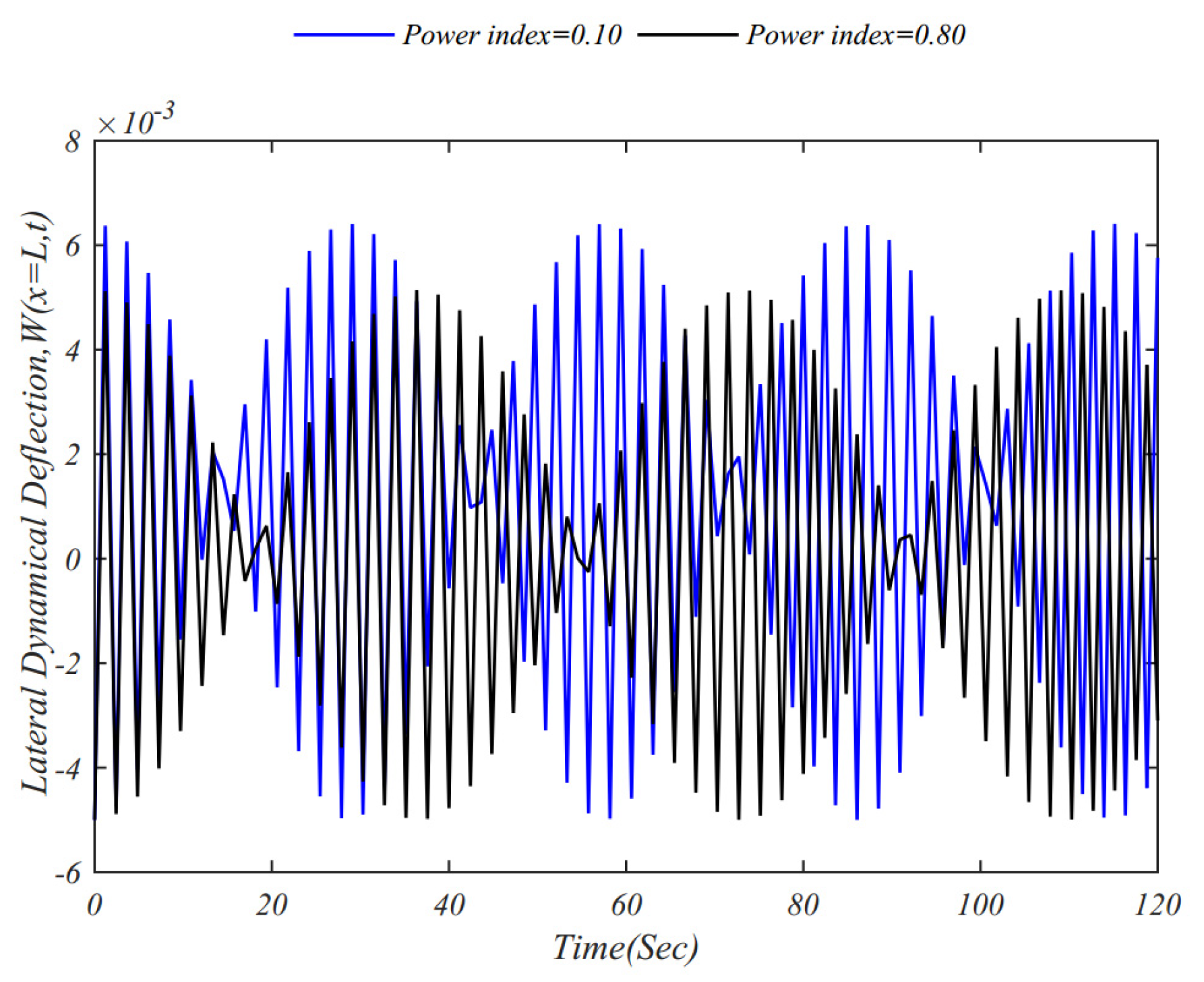
A validation study is first conducted by comparing the present results with those available in the literature. Neglecting the external loads in Equation (A3), the natural frequencies of a clamped-free FG beam p = 0 are evaluated and benchmarked against the results reported by Rao [52] for various slenderness ratios (see Table 3). The comparison from this table reveals an excellent agreement, thereby confirming the accuracy and reliability of the proposed formulation. The numerical analysis is then extended to investigate the influence of the power-law index on the system’s time response, as illustrated in Figure 2. The results indicate that the dynamic response initially grows and subsequently decays within a harmonic envelope, a characteristic signature of beating phenomena. Furthermore, it is observed that increasing the power-law index leads to a reduction in the lateral dynamic deflection, while simultaneously lengthening the beating period.
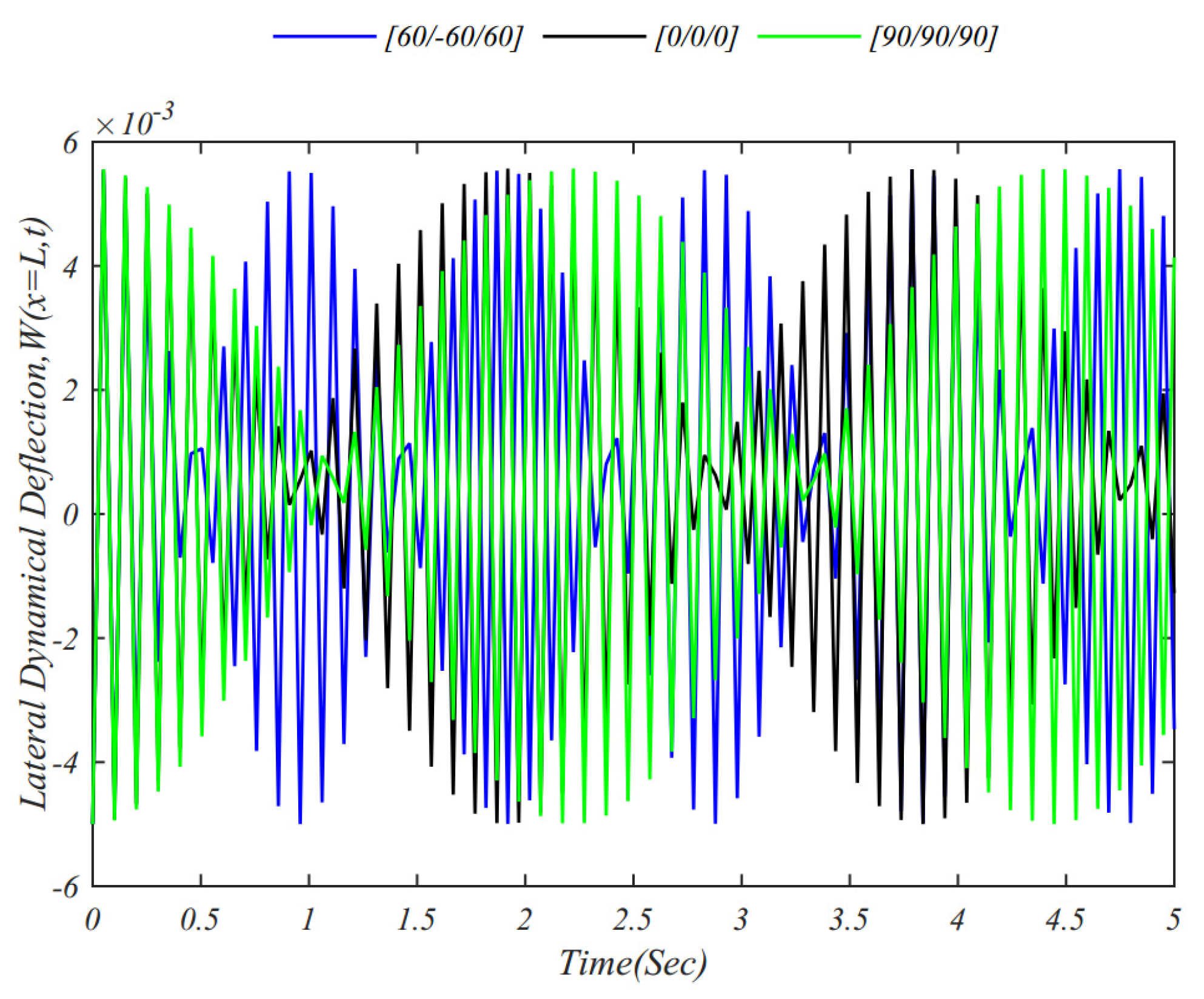
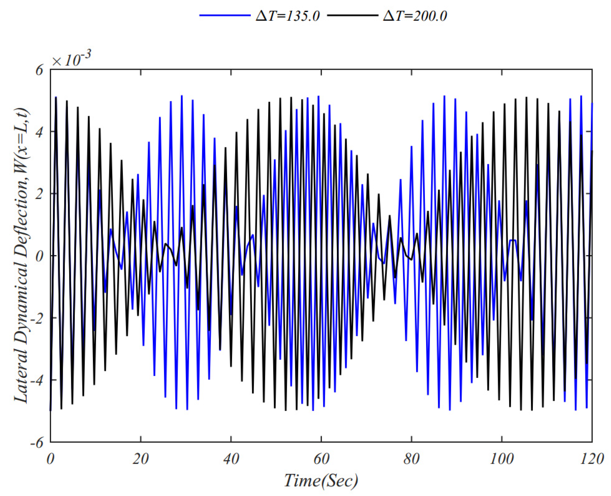
Figure 3 also exhibits the effect of the stacking sequence on the time history of the system, whose results show that the fiber-reinforced composite laminated cantilever beam with an angle-ply stacking sequence, [60/−60/60] features the highest beating frequency, followed by a [0/0/0] stacking sequence, whereas the composite laminated cantilever beam with stacking sequence [90/90/90] has the highest beating period among these three stacking sequences. Moreover, Figure 4 shows the effect of a uniform temperature rise on the time history of the system.
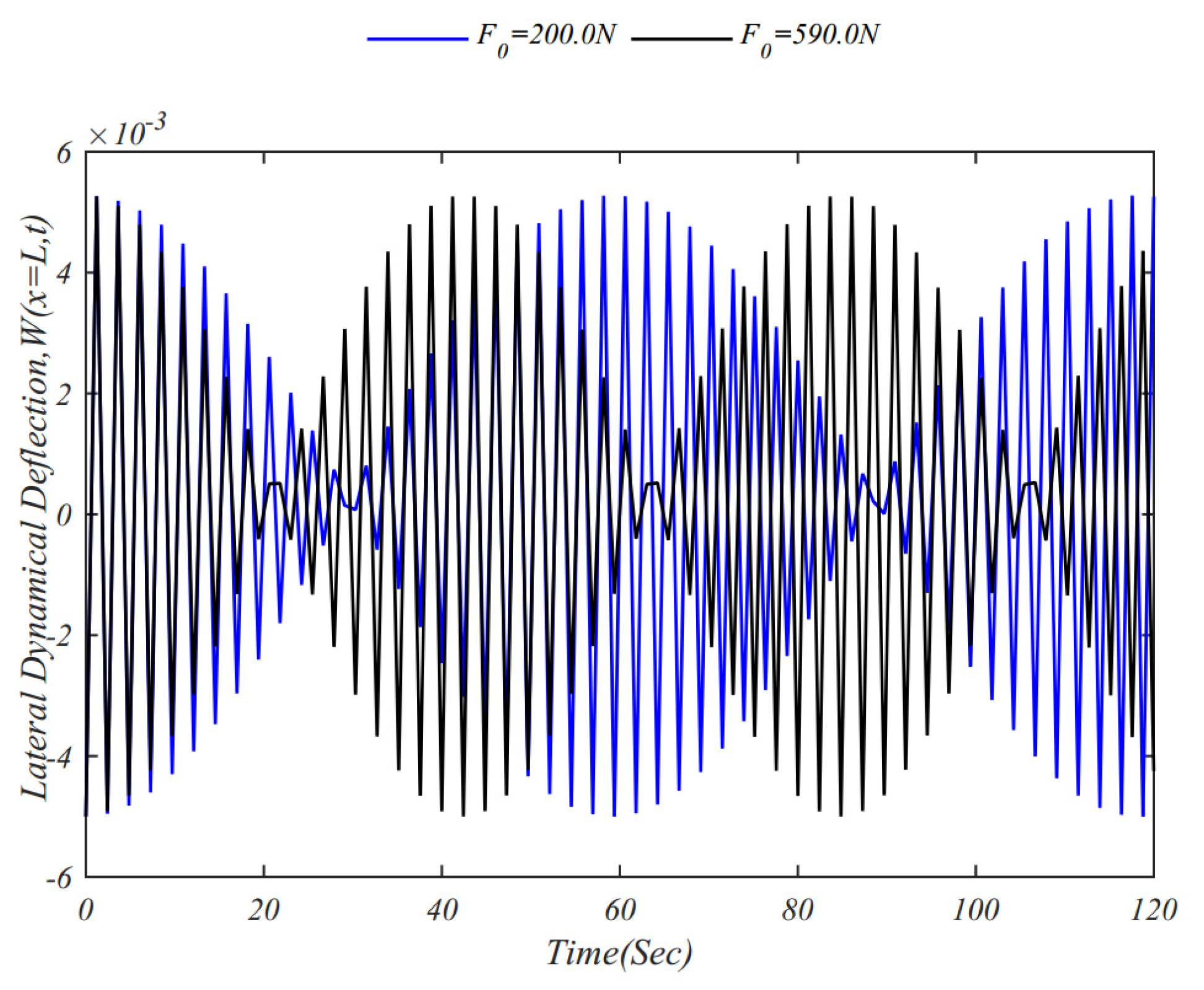
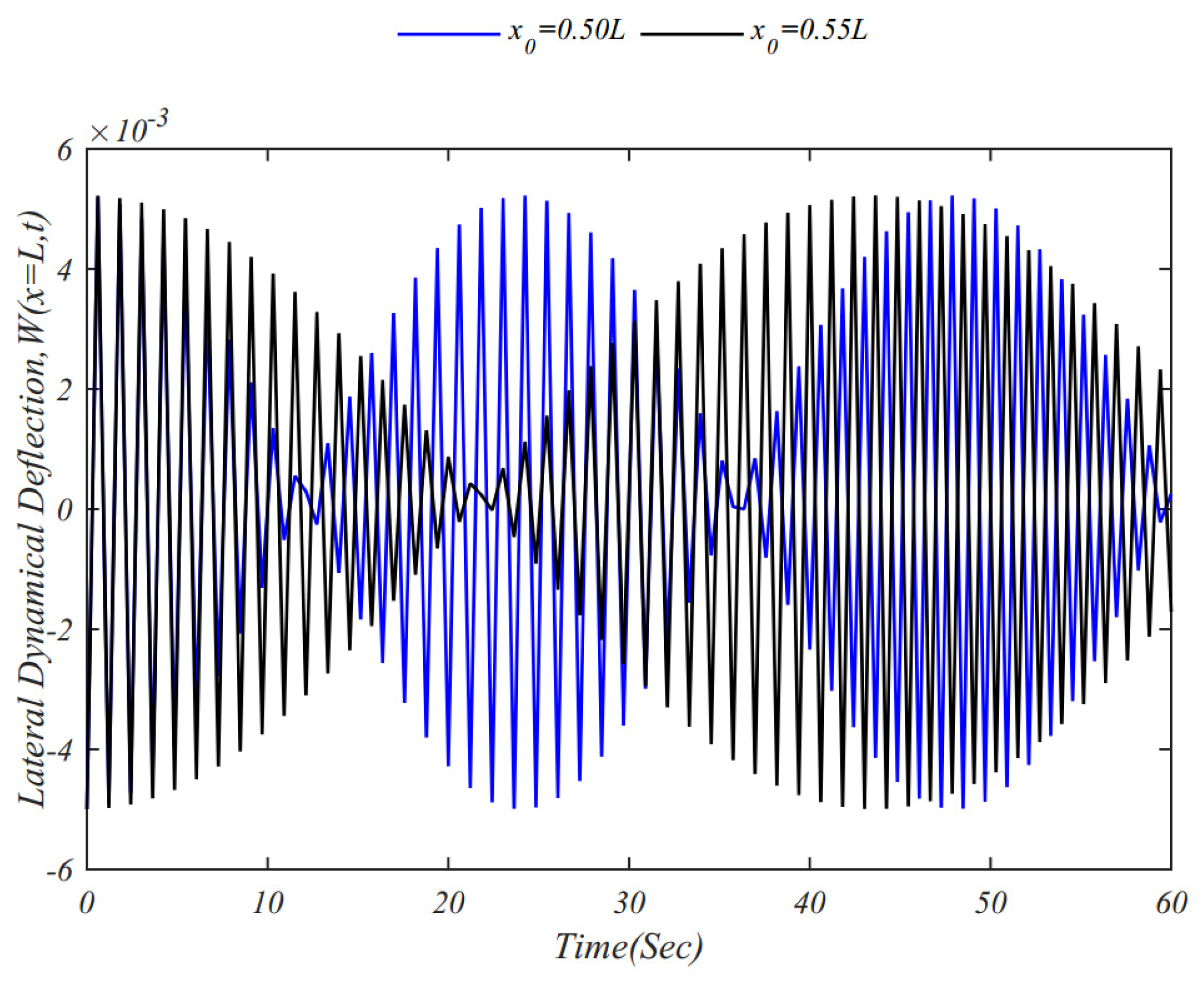
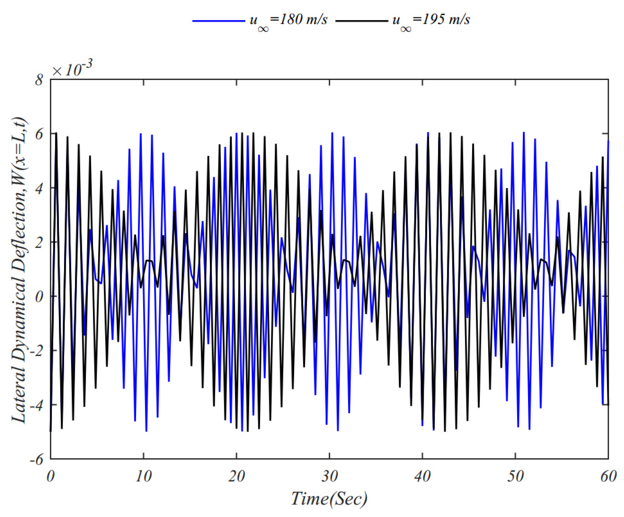
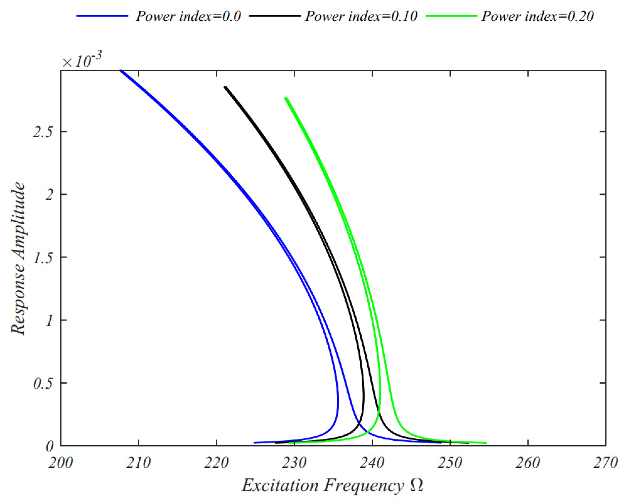
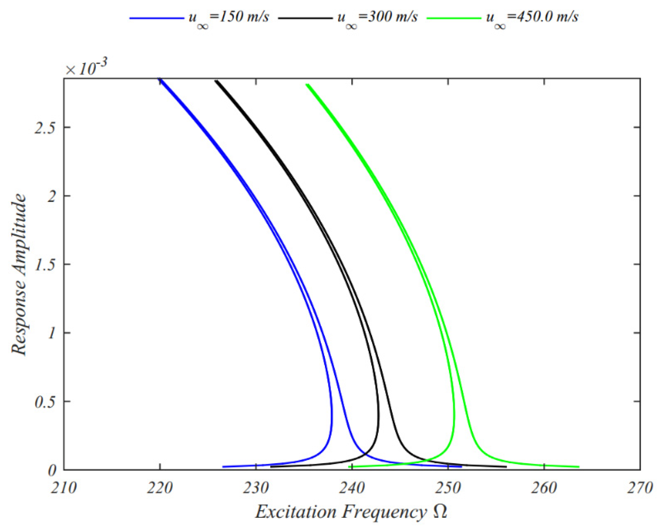
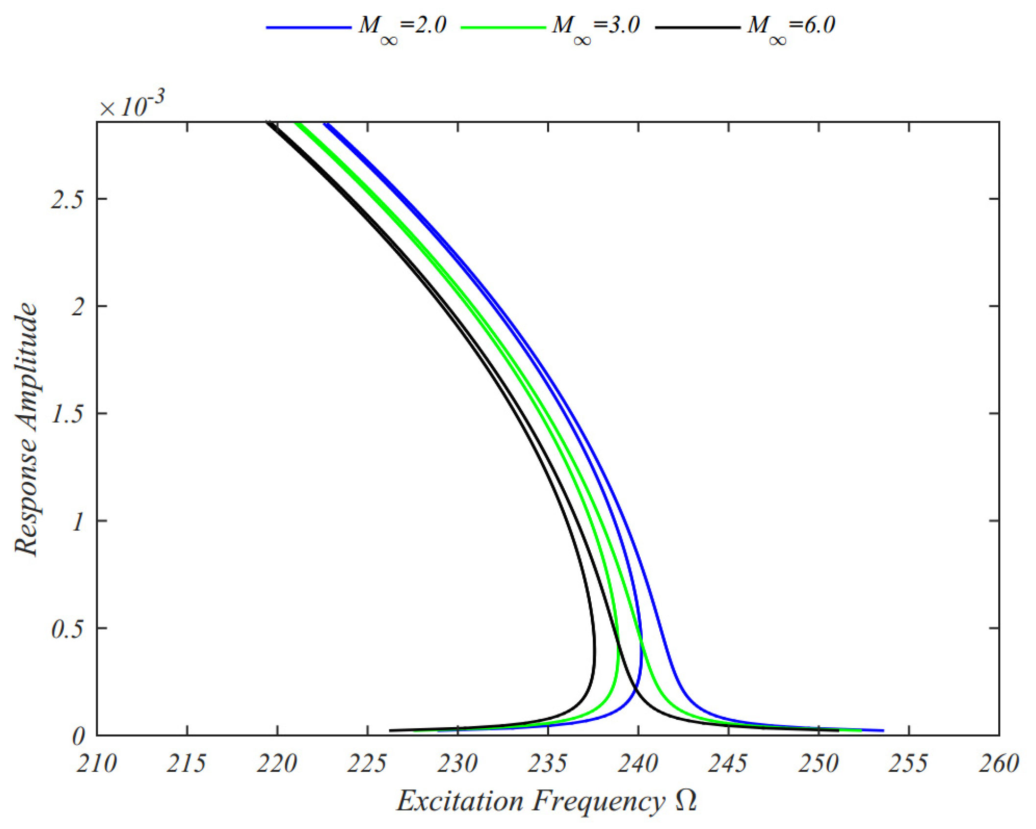
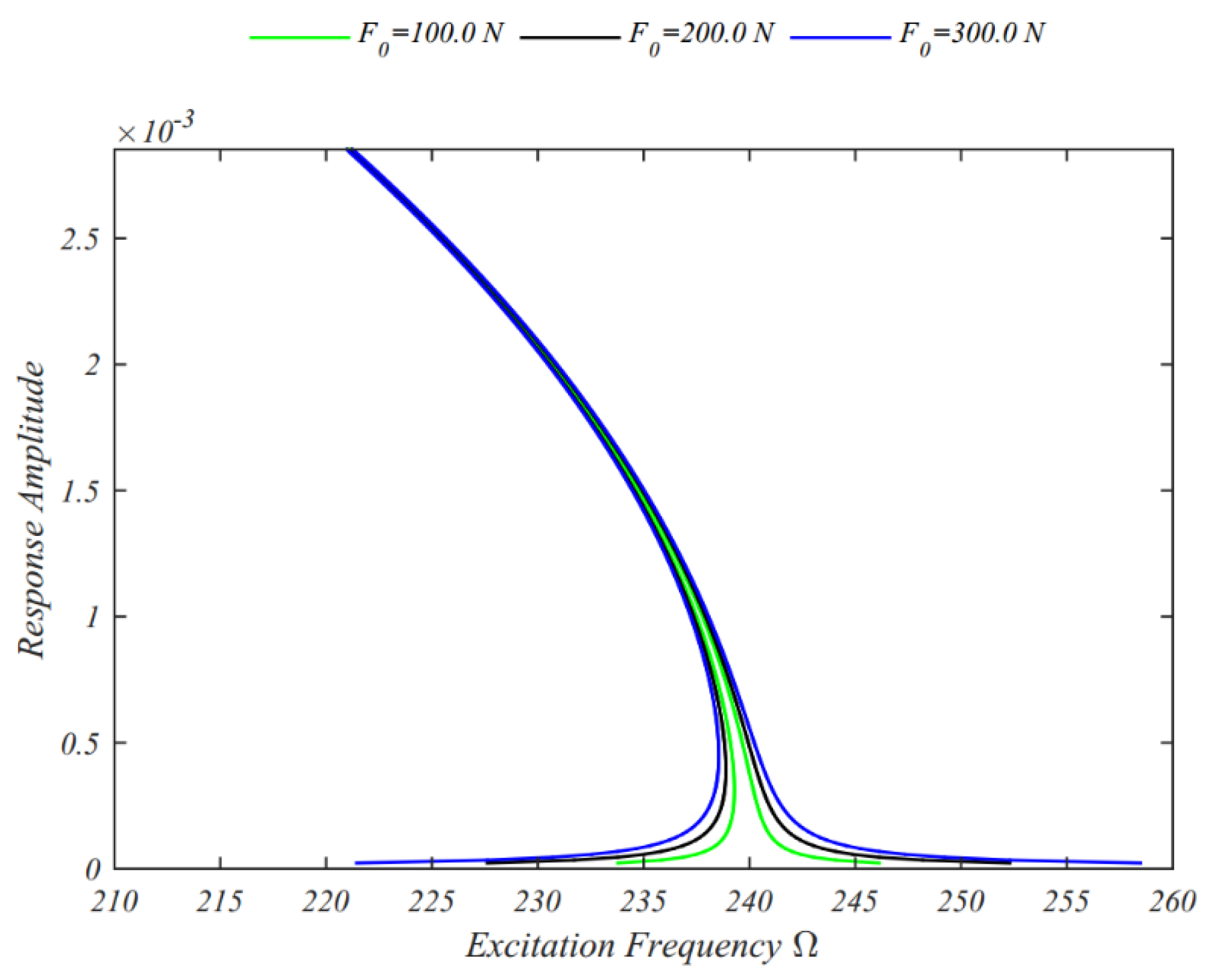
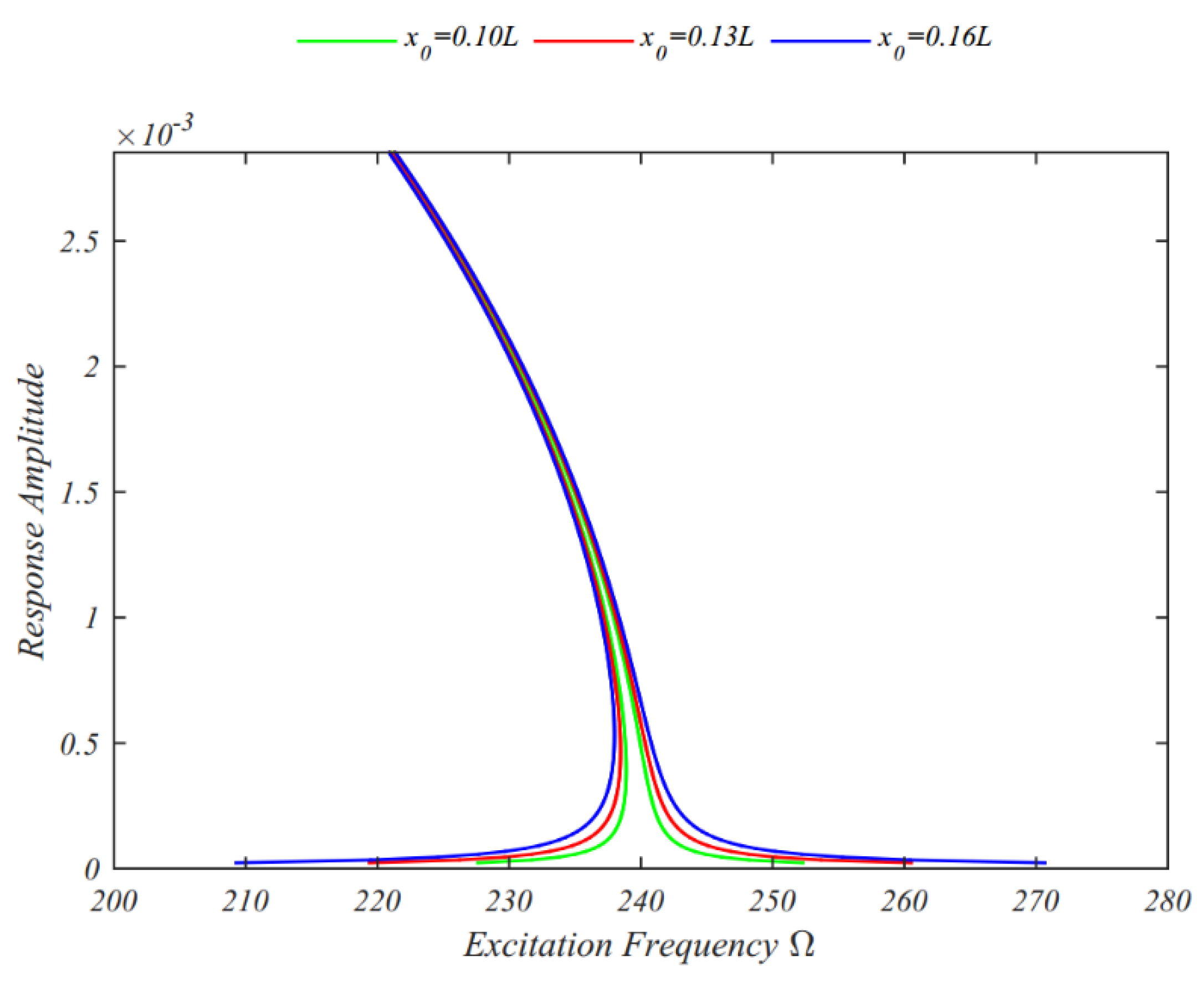
The results indicate that increasing the temperature leads to a pronounced reduction in the beating frequency, which is attributed to the expected decrease in system stiffness. However, the lateral dynamic deflection remains essentially unaffected. Figure 5 and Figure 6 illustrate the influence of the excitation force amplitude and its location, respectively, on the time history of the response. A systematic analysis reveals that the beating period shortens as the excitation amplitude increases, while it lengthens considerably when the excitation force is applied closer to the free end of the beam. The effects of aerodynamic parameters are shown in Figure 7 and Figure 8. As observed in Figure 7, the beating period becomes longer with higher free-stream air velocity, whereas Figure 8 shows that it decreases with an increase in Mach number. A broader parametric study is presented in Figure 9, Figure 10, Figure 11, Figure 12, Figure 13, Figure 14 and Figure 15, highlighting the sensitivity of the frequency response curves (FRCs) to key parameters such as the power index, stacking sequence, uniform temperature rise, free-stream air velocity, Mach number, and the amplitude and location of the excitation force. These FRCs are characterized by two distinct branches: the upper branch corresponds to stable solutions, while the lower branch encompasses both stable and unstable responses. In all cases, the FRCs exhibit a leftward shift, indicative of softening behavior. This softening leads to the occurrence of jump phenomena, whose small variations in excitation frequency cause abrupt changes in response amplitude due to system nonlinearity. Figure 9 demonstrates the role of the power index: fiber-reinforced composite (FRC) laminated beams coated with homogeneous SUS304 material exhibit higher amplitudes and stronger softening than those coated with FG materials. Nevertheless, increasing the power index reduces both the degree of softening and the jump magnitude, while shifting the response toward higher excitation frequencies.
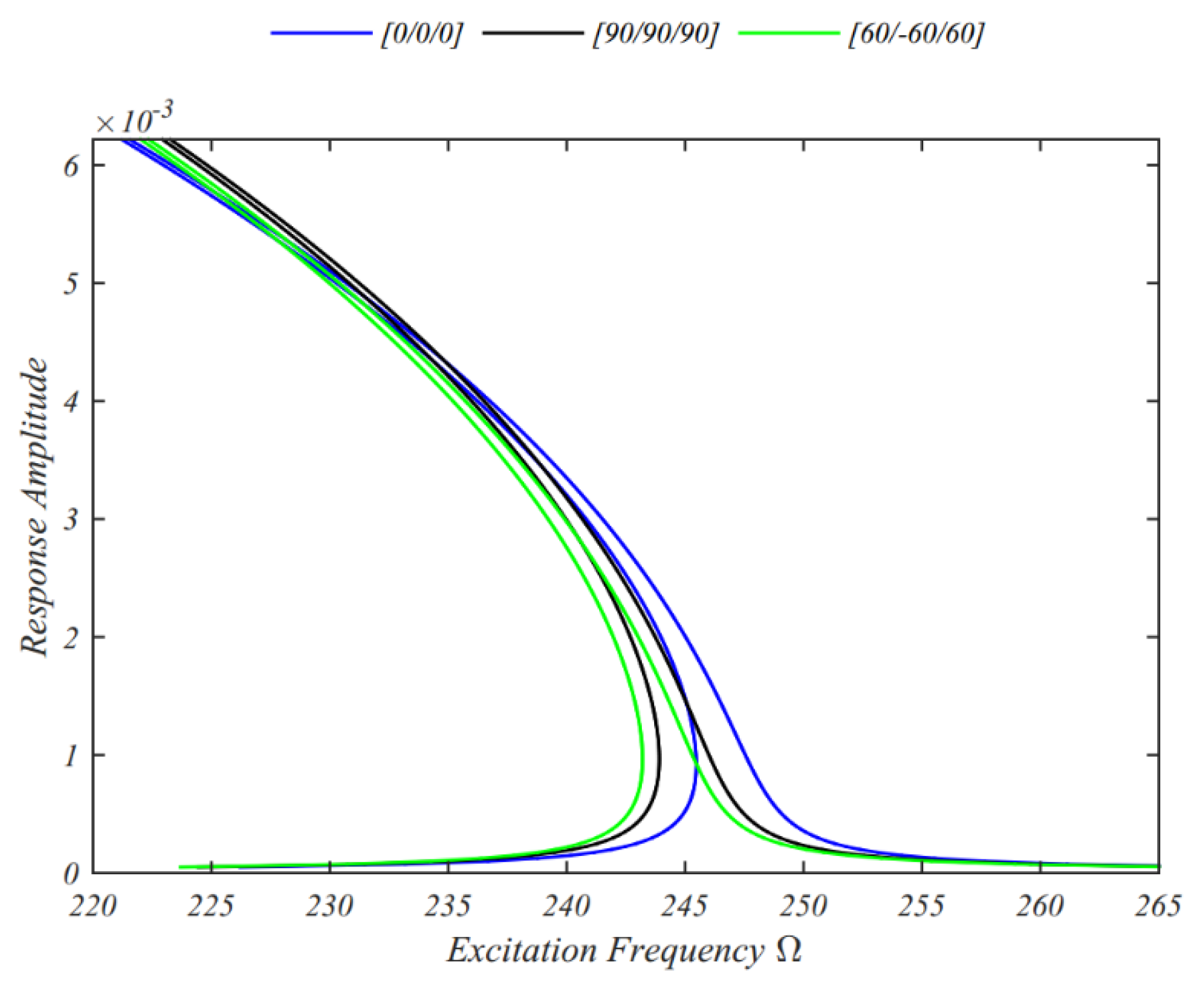
The influence of stacking sequence is presented in Figure 10. Laminated cantilever beams with a [0/0/0] sequence display the strongest nonlinear softening behavior, followed by [60/−60/60] and [90/90/90]. Interestingly, while the peak amplitude remains constant across sequences, it occurs at progressively higher excitation frequencies as the layup is altered from [0/0/0] to [60/−60/60] and [90/90/90]. Figure 11 examines the effect of a uniform temperature rise. Higher temperatures are found to reduce the degree of softening, as well as the jump height and peak amplitude of the nonlinear response, while simultaneously shifting the resonance toward higher frequencies. Figure 12 and Figure 13 analyze aerodynamic effects. Increasing the free-stream air velocity reduces the softening behavior, the jump height, and the peak amplitude, while raising the excitation frequencies (Figure 12). Conversely, an increase in Mach number intensifies the softening behavior, though the jump height and peak amplitude remain nearly unchanged, with the response shifting toward lower excitation frequencies (Figure 13). Finally, Figure 14 and Figure 15 address the excitation force. Both higher amplitudes and reduced distance of the applied load from the free end broaden the overall response region. Nevertheless, the degree of softening and the peak amplitude remain largely unaffected.

5. Conclusions

This study has investigated the nonlinear forced vibration behavior of fiber-reinforced composite laminated beams coated with functionally graded materials (FGMs) and subjected to combined aero-thermoelastic loading and a concentrated harmonic point force. The governing nonlinear partial differential equations were derived using Euler–Bernoulli beam theory in conjunction with von Kármán-type geometric nonlinearities and a modified third-order piston theory. By neglecting axial inertia, these equations were reduced to a single governing relation, which was then discretized through the Galerkin method, resulting in a nonlinear ordinary differential equation. The reduced model was subsequently solved analytically using the method of multiple time scales (MTS). A comprehensive numerical analysis was carried out to examine the sensitivity of the system’s response to key parameters, including the power-law index, stacking sequence, uniform temperature rise, amplitude and position of the point load, free-stream air velocity, and Mach number. The investigation focused in particular on the evolution of lateral dynamic deflection and the characteristics of the frequency response curves (FRCs). The study reveals several important trends regarding the nonlinear dynamic behavior of fiber-reinforced composite laminated beams coated with FGMs. Increasing the power index reduces the lateral dynamic deflection while extending the beating period. It also weakens the softening behavior and diminishes the intensity of jump phenomena, both of which occur at higher excitation frequencies. The stacking sequence plays a decisive role. Beams with an angle-ply layup of [60/−60/60] exhibit the highest beating frequency, followed by the [0/0/0] and [90/90/90] configurations. In contrast, the strongest nonlinear softening behavior is observed in beams with a [0/0/0] layup, with decreasing intensity for [60/−60/60] and [90/90/90]. While the peak amplitude remains unchanged across these sequences, it consistently shifts to higher excitation frequencies as the layup changes from [0/0/0] to [90/90/90].
Thermal effects are also significant. A rise in temperature markedly reduces the beating frequency owing to a reduction in stiffness, while leaving the lateral deflection essentially unchanged. With regard to FRCs, higher temperatures lead to weaker softening behavior, reduced jump intensity, and smaller peak amplitudes, although the resonance shifts toward higher excitation frequencies. The characteristics of the excitation force influence the response in different ways. Increasing its amplitude shortens the beating period, whereas moving the point of application closer to the beam’s free end lengthens it. Moreover, either a larger excitation amplitude or a location closer to the free end broadens the overall response region, though without altering the degree of softening or the peak amplitude. Aerodynamic parameters introduce further complexity. The beating period grows significantly with higher free-stream air velocity but decreases with increasing Mach number. For FRCs, higher velocities reduce the softening response, the jump magnitude, and the peak amplitude, while shifting the response toward higher frequencies. In contrast, an increase in Mach number amplifies the softening behavior, though the jump and peak amplitude remain essentially unchanged and occur at lower frequencies. Finally, the coating material itself affects the dynamics. Beams coated with homogeneous SUS304 material exhibit larger response amplitudes and stronger softening behavior than those coated with FGMs, underscoring the influence of material gradation on the nonlinear response.

Author Contributions

Conceptualization, F.T. and R.D.; Methodology, M.A., F.T. and R.D.; Validation, M.A., F.T. and R.D.; Formal analysis, F.T. and R.D.; Investigation, M.A., F.T. and R.D.; Writing—original draft, M.A.; Writing—review & editing, F.T. and R.D. All authors have read and agreed to the published version of the manuscript.

Funding

This research received no external funding.

Data Availability Statement

The original contributions presented in this study are included in the article. Further inquiries can be directed to the corresponding author.

Conflicts of Interest

The authors declare no conflict of interest.

Appendix A

μ ^ 0 = 1 2 0 L ζ ψ 2 d x 0 L I 0 ψ 2 ( x ) d x
μ ^ 1 = 1 2 0 L ζ ξ ψ x 2 ψ 2 d x 0 L I 0 ψ 2 ( x ) d x
ω 0 2 = 0 L a 0 ψ ( x ) d x 0 L I 0 ψ 2 ( x ) d x
η ^ 2 = 0 L a 2 ψ ( x ) d x 0 L I 0 ψ 2 ( x ) d x
η ^ 3 = 0 L a 3 ψ ( x ) d x 0 L I 0 ψ 2 ( x ) d x
f ^ p = F 0 ψ ( x 0 ) 0 L I 0 ψ 2 ( x ) d x
χ 0 = ω 0 μ ^ 0 2 2 ω 0
χ 1 = 1 8 ω 0 10 η ^ 2 2 3 ω 0 2 3 η ^ 3
χ 2 = f ^ p 2 4 ω 0 2
χ 3 = 1 16 μ ^ 1 2

References

  1. Asadi, H.; Beheshti, A.R. On the nonlinear dynamic responses of FG-CNTRC beams exposed to aerothermal loads using third-order piston theory. Acta Mech. 2018, 229, 2413–2430. [Google Scholar] [CrossRef]
  2. Yao, G.; Zhang, Y.M.; Li, C.Y.; Yang, Z. Stability analysis and vibration characteristics of an axially moving plate in aero-thermal environment. Acta Mech. 2016, 227, 3517–3527. [Google Scholar] [CrossRef]
  3. Yao, G.; Xie, Z.; Zhu, L.; Zhang, Y. Nonlinear vibrations of an axially moving plate in aero-thermal environment. Nonlinear Dynam. 2021, 105, 2921–2933. [Google Scholar] [CrossRef]
  4. Li, P.; Yang, Z.; Tian, W. Nonlinear aeroelastic analysis and active flutter control of functionally graded piezoelectric material plate. Thin Walled Struct. 2023, 183, 110323. [Google Scholar] [CrossRef]
  5. Alimoradzadeh, M.; Tornabene, F.; Dimitri, R. Aeroelastic Oscillations of Cantilever Beams Reinforced by Carbon Nanotubes Based on a Modified Third-Order Piston Theory. Appl. Sci. 2025, 15, 8700. [Google Scholar] [CrossRef]
  6. El-Borgi, S.; Erdogan, F.; Hatira, F. Ben Stress Intensity Factors for an Interface Crack between a Functionally Graded Coating and a Homogeneous Substrate. Int. J. Fract. 2003, 123, 139–162. [Google Scholar] [CrossRef]
  7. Guo, L.C.; Wang, Z.H.; Zhang, L. A Fracture Mechanics Problem of a Functionally Graded Layered Structure with an Arbitrarily Oriented Crack Crossing the Interface. Mech. Mater. 2012, 46, 69–82. [Google Scholar] [CrossRef]
  8. Tornabene, F.; Fantuzzi, N.; Bacciocchi, M. Free Vibrations of Free-Form Doubly-Curved Shells Made of Functionally Graded Materials Using Higher-Order Equivalent Single Layer Theories. Compos. Part B Eng. 2014, 67, 490–509. [Google Scholar] [CrossRef]
  9. Liew, K.M.; Lei, Z.X.; Zhang, L.W. Mechanical analysis of functionally graded carbon nanotube reinforced composites: A Review. Compos Struct. 2015, 120, 90–97. [Google Scholar] [CrossRef]
  10. Zhang, J.; Zheng, W. Elastoplastic buckling of FGM beams in thermal environment. Contin. Mech. Thermodyn. 2021, 33, 151–161. [Google Scholar] [CrossRef]
  11. Malikan, M.; Wiczenbach, T.; Eremeyev, V.A. Thermal buckling of functionally graded piezomagnetic micro- and nanobeams presenting the flexomagnetic effect. Contin. Mech. Thermodyn. 2022, 34, 1051–1066. [Google Scholar] [CrossRef]
  12. Dowell, E.H. Nonlinear oscillations of a fluttering plate. AIAA J. 1966, 4, 1267–1275. [Google Scholar] [CrossRef]
  13. Dowell, E.H. Nonlinear oscillations of a fluttering plate. II. AIAA J. 1967, 5, 1856–1862. [Google Scholar] [CrossRef]
  14. Ye, W.L.; Dowell, E.H. Limit cycle oscillation of a fluttering cantilever plate. AIAA J. 1991, 29, 1929–1936. [Google Scholar] [CrossRef]
  15. Shiau, L.C.; Lu, L.T. Nonlinear flutter of two-dimensional simply supported symmetric composite laminated plates. J. Aircraft. 1992, 29, 140–145. [Google Scholar] [CrossRef]
  16. Song, Z.G.; Li, F.M. Investigations on the flutter properties of supersonic panels with different boundary conditions. Int. J. Dynam. Control 2014, 3, 346–353. [Google Scholar] [CrossRef]
  17. Sohn, K.J.; Kim, J.H. Nonlinear thermal flutter of functionally graded panels under a supersonic flow. Compos. Struct. 2009, 88, 380–387. [Google Scholar] [CrossRef]
  18. Koo, K.N.; Hwang, W.S. Effects of hysteretic and aerodynamic damping on supersonic panel flutter of composite plates. J. Sound Vib. 2004, 273, 569–583. [Google Scholar] [CrossRef]
  19. Shin, W.H.; Oh, I.K.; Lee, I. Nonlinear flutter of aerothermally buckled composite shells with damping treatments. J. Sound Vib. 2009, 324, 556–569. [Google Scholar] [CrossRef]
  20. Song, Z.G.; Li, F.M. Aeroelastic analysis and active flutter control of nonlinear lattice sandwich beams. Nonlinear Dyn. 2014, 76, 7–68. [Google Scholar] [CrossRef]
  21. Natarajan, S.; Kaleeswaran, K.; Manickam, G. Functionally graded material panel flutter by cell-based smoothed finite elements. J. Coupled Syst. Multiscale Dynam. 2013, 1, 205–215. [Google Scholar] [CrossRef]
  22. Natarajan, S.; Manickam, G.; Bordas, S. Supersonic flutter analysis of functionally graded material plates with cracks. Front Aerosp. Eng. 2013, 2, 91–97. [Google Scholar]
  23. Abbas, J.F.; Ibrahim, R.A.; Gibson, R.F. Nonlinear flutter of orthotropic composite panel under aerodynamic heating. AIAA J. 1993, 31, 1478–1488. [Google Scholar] [CrossRef]
  24. Xue, D.Y.; Mei, C. Finite element nonlinear panel flutter with arbitrary temperatures in supersonic flow. AIAA J. 1993, 31, 154–162. [Google Scholar] [CrossRef]
  25. Zhao, H.; Cao, D. A study on the aero-elastic flutter of stiffened laminated composite panel in the supersonic flow. J. Sound Vib. 2013, 332, 4668–4679. [Google Scholar] [CrossRef]
  26. Dixon, L.R.; Mei, C. Finite element analysis of large-amplitude panel flutter of thin laminates. AIAA J. 1993, 31, 701–707. [Google Scholar] [CrossRef]
  27. Kouchakzadeh, M.A.; Rasekh, M.; Haddadpour, H. Panel flutter analysis of general laminated composite plates. Compos Struct. 2010, 92, 2906–2915. [Google Scholar] [CrossRef]
  28. Camacho, P.; Akhavan, H.; Ribeiro, P. Linear aeroelastic analysis of cantilever hybrid composite laminated plates with curvilinear fibres and carbon nanotubes. Compos Struct. 2021, 266, 113765. [Google Scholar] [CrossRef]
  29. Alimoradzadeh, M.; Akbas, S.D. Superharmonic and subharmonic resonances of a carbon nanotube-reinforced composite beam. Adv. Nano Res. 2022, 12, 353–363. [Google Scholar]
  30. Alimoradzadeh, M.; Tornabene, F.; Esfarjani, S.M.; Dimitri, R. Finite strain-based theory for the superharmonic and subharmonic resonance of beams resting on a nonlinear viscoelastic foundation in thermal conditions, and subjected to a moving mass loading. Int J. Non-Linear Mech. 2023, 148, 104271. [Google Scholar] [CrossRef]
  31. Alimoradzadeh, M.; Akbaş, Ş.D. Thermal nonlinear dynamic and stability of carbon nanotube reinforced composite beams. Steel Compos. Struct. 2023, 46, 637–647. [Google Scholar]
  32. Alimoradzadeh, M.; Heidari, H.; Tornabene, F.; Dimitri, R. Thermo-Mechanical Buckling and Non-Linear Free Oscillation of Functionally Graded Fiber-Reinforced Composite Laminated (FG-FRCL) Beams. Appl. Sci. 2023, 13, 4904. [Google Scholar] [CrossRef]
  33. Alimoradzadeh, M.; Akbaş, Ş.D. Nonlinear free vibration analysis of a composite beam reinforced by carbon nanotubes. Steel Compos. Struct. 2023, 46, 335–344. [Google Scholar]
  34. Alimoradzadeh, M.; Akbas, S.D. Nonlinear vibration analysis of carbon nanotube-reinforced composite beams resting on nonlinear viscoelastic foundation. Geomech. Eng. 2023, 32, 125–135. [Google Scholar]
  35. Samadpour, M.; Asadi, H.; Wang, Q. Nonlinear aero-thermal flutter postponement of supersonic laminated composite beams with shape memory alloys. Eur. J. Mech. Solid 2016, 57, 18–28. [Google Scholar] [CrossRef]
  36. Alimoradzadeh, M.; Tornabene, F.; Dimitri, R. Nonlinear axial-lateral coupled vibration of functionally graded-fiber reinforced composite laminated (FG-FRCL) beams subjected to aero-thermal loads. Int. J. Non Linear Mech. 2024, 159, 104612. [Google Scholar] [CrossRef]
  37. Kong, S.; Zhou, S.; Nie, Z.; Wang, K. The size-dependent natural frequency of Bernoulli–Euler micro-beams. Int. J. Eng. Sci. 2008, 46, 427–437. [Google Scholar] [CrossRef]
  38. Fernandes, R.; Mousavi, S.M.; El-Borgi, S. Free and forced vibration nonlinear analysis of a microbeam using finite strain and velocity gradients theory. Acta Mech. 2016, 227, 2657–2670. [Google Scholar] [CrossRef]
  39. Ramezani, S. A micro scale geometrically non-linear Timoshenko beam model based on strain gradient elasticity theory. Int. J. Non Linear Mech. 2012, 47, 863–873. [Google Scholar] [CrossRef]
  40. Ebrahimi, F.; Jafari, A. A higher-order thermomechanical vibration analysis of temperature-dependent FGM beams with porosities. J. Eng. 2016, 2016, 9561504. [Google Scholar] [CrossRef]
  41. Chen, Y.; Fu, Y.; Zhong, J.; Tao, C. Nonlinear dynamic responses of fiber-metal laminated beam subjected to moving harmonic loads resting on tensionless elastic foundation. Compos. Part B Eng. 2017, 131, 253–259. [Google Scholar] [CrossRef]
  42. Daniel, I.M.; Ishai, O.; Daniel, I.M.; Daniel, I. Engineering Mechanics of Composite Materials; Oxford University Press: New York, NY, USA, 2006. [Google Scholar]
  43. Xiang, H.J.; Yang, J. Free and forced vibration of a laminated FGM Timoshenko beam of variable thickness under heat conduction. Compos. Part B Eng. 2008, 39, 292–303. [Google Scholar] [CrossRef]
  44. Chen, W.J.; Li, X.P. Size-dependent free vibration analysis of composite laminated Timoshenko beam based on new modified couple stress theory. Arch. Appl. Mech. 2013, 83, 431–444. [Google Scholar] [CrossRef]
  45. McHugh, K.A.; Beran, P.; Freydin, M.; Dowell, E.H. Flutter and limit cycle oscillations of a cantilevered plate in supersonic/hypersonic flow. Proc. IFASD 2019, 1, 2–3. [Google Scholar]
  46. Mohammad-Abadi, M.; Daneshmehr, A.R. Modified couple stress theory applied to dynamic analysis of composite laminated beams by considering different beam theories. Int. J. Eng. Sci. 2015, 87, 83–102. [Google Scholar] [CrossRef]
  47. Inman, D.J. Vibration with Control; John Wiley & Sons, University of Michigan: Hoboken, NJ, USA, 2017. [Google Scholar]
  48. Norouzi, H.; Younesian, D. Chaotic vibrations of beams on nonlinear elastic foundations subjected to reciprocating loads. Mech. Res. Commun. 2015, 69, 121–128. [Google Scholar] [CrossRef]
  49. Laura, P.A.; Pombo, J.L.; Susemihl, E.A. A note on the vibrations of a clamped-free beam with a mass at the free end. J. Sound Vib. 1974, 37, 161–168. [Google Scholar] [CrossRef]
  50. Nayfeh, A.H.; Mook, D.T.; Holmes, P. Nonlinear oscillations. ASME J. Appl. Mech. 1980, 47, 692. [Google Scholar] [CrossRef]
  51. Tao, C.; Fu, Y.M.; Dai, H.L. Nonlinear dynamic analysis of fiber metal laminated beams subjected to moving loads in thermal environment. Compos. Struct. 2016, 140, 410–416. [Google Scholar] [CrossRef]
  52. Rao, S.S. Vibration of Continuous Systems; Wiley: New York, NY, USA, 2007; p. 317. [Google Scholar]
Figure 1. Configuration of the multilayer composite beam exposed to combined aero-thermal loading and a concentrated harmonic force.
Jcs 09 00539 g001
Figure 2. Influence of the power-law index on the system’s time response x 0 = 0.8 L ,   Δ T = 10.0   ° C .
Jcs 09 00539 g002
Figure 3. Influence of the stacking sequence on the time history x 0 = 0.2 L ,   Δ T = 30.0   ° C ,   p = 0.20 .
Jcs 09 00539 g003
Figure 4. Influence of the uniform temperature rise on the time history x 0 = 0.8 L , p = 0.2 .
Jcs 09 00539 g004
Figure 5. Influence of the load amplitude on the time history   x 0 = 0.8 L ,     Δ T =   75.0   ° C ,     p   = 0.2 .
Jcs 09 00539 g005
Figure 6. Influence of the load position on the time history Δ T = 85.0   ° C ,     p = 0.25 .
Jcs 09 00539 g006
Figure 7. Influence of the free stream air velocity on the time history x 0   =   0.8 L ,     Δ T = 10.0   ° C ,   p   =   0.2 .
Jcs 09 00539 g007
Figure 8. Influence of the Mach number on the time history x 0 = 0.15 L , Δ T = 30.0   ° C ,   p = 0.2 .
Jcs 09 00539 g008
Figure 9. Influence of the power index on the FRCs   x 0 = 0.1 L , Δ T = 10.0   ° C .
Jcs 09 00539 g009
Figure 10. Influence of the stacking sequence on the FRCs Γ = 0.006 ,   x 0 = 0.2 L , Δ T = 10.0   ° C ,   p = 0.8 .
Jcs 09 00539 g010
Figure 11. Influence of the temperature rise on the FRCs x 0 = 0.1 L ,     p = 0.1 ,     Δ T   [ ° C ] .
Jcs 09 00539 g011
Figure 12. Influence of the velocity of the free air on the FRCs   x 0 = 0.1 L ,     Δ T = 10.0   ° C ,     p = 0.1 .
Jcs 09 00539 g012
Figure 13. Influence of the Mach number on the FRCs x 0 = 0.1 L ,   Δ T = 10.0   ° C ,     p = 0.1 .
Jcs 09 00539 g013
Figure 14. Influence of the excitation amplitude on the FRCs x 0 = 0.1 L ,     Δ T = 10.0   ° C ,   p = 0.1 .
Jcs 09 00539 g014
Figure 15. Influence of the load location on the FRCs Δ T = 10.0   ° C ,     p = 0.1 .
Jcs 09 00539 g015
Table 1. Material properties of the FGM layers [40].
MaterialProperties
E (GPa) ρ ( K g m 3 ) ϑ α ( 1 k )
S i 3 N 4 348.4323700.245.8723 × 10−6
SUS304201.0481660.326212.330 × 10−6
Table 2. Material properties of the composite layers [51].
Material Properties (Glass-Polymer Composite)
E 1 , E 2 ( G P a ) G 12 (GPa) ρ ( K g m 3 ) ϑ 12 α 1 ( 1 k ) α 2 ( 1 k )
50, 15.24.72000.00.2546.34 × 10−623.3 × 10⁻⁶
Table 3. Comparative results for fundamental frequencies of a cantilever beam u = 0 .
L h
Fundamental Frequency ω L ( r a d s )
Present WorkRao [52]
ϑ 0
ϑ = 0
50.0507.0912492.2704492.2683
60.0352.1467341.8544341.8530
70.0258.7200251.1584251.1573
80.0198.0825192.2931192.2923
90.0156.5096151.9353151.9346
100.0126.7728123.0676123.0671
Disclaimer/Publisher’s Note: The statements, opinions and data contained in all publications are solely those of the individual author(s) and contributor(s) and not of MDPI and/or the editor(s). MDPI and/or the editor(s) disclaim responsibility for any injury to people or property resulting from any ideas, methods, instructions or products referred to in the content.