Abstract
Harnessing solar energy is crucial for applications such as water desalination through solar collectors, where efficient conversion of solar radiation into thermal energy is required. In this study, electroless nickel–phosphorus (Ni-P) coatings and their carbon black (CB) nanoparticle composites were successfully deposited and evaluated as selective solar absorbers. The coatings exhibited compact, crack-free, and amorphous structures composed mainly of Ni(OH)2 and NiOOH, as confirmed by SEM-EDS, XRD, FTIR, and Raman analyses. Increasing the pH enhanced the deposition rate and coating thickness while reducing the phosphorus content. Incorporation of CB nanoparticles was confirmed, though it slightly decreased coating thickness. Optical characterization revealed high absorptance and low emissivity across all samples, with the Ni-P coating produced at higher pH (C1) achieving the best performance (brightness L* = 29.0; figure of merit α − ε = 0.84). Aging tests further demonstrated the resilience of this sample, maintaining a figure of merit of 0.81. These findings establish Ni-P coatings, particularly at higher pH, as promising and safer alternatives to conventional chromium-based solar selective coatings.
1. Introduction
The sun has a major energetic contribution to the Earth’s system. Some of this energy is reflected and absorbed by the atmosphere and clouds, but an important fraction is absorbed across lands and oceans. From the 340 MW/m2 provided by the sun to the outer regions of the atmosphere, only 164 MW/m2 is absorbed by the Earth’s surface [1]. Therefore, it is crucial to harness a fraction of this incoming radiation, which is a challenge because of its low density and intermittency [2,3]. To that end, several technologies have been continuously developed, leading to distinct types of solar systems and their respective roles in modern applications. Although these units share the ultimate goal of utilizing solar radiation, they clearly differ, mostly with respect to the type of energy converted, operating principles, and applicability.
Various advanced materials have also been explored for energy and electromagnetic applications, highlighting the broad interest in composites with enhanced absorption, stability, and morphological control. For instance, recent studies report on MoS2 anchored on graphene oxide composites that exhibit exceptional electromagnetic wave absorption [4]. Graphene-supported TiO2 nanosheet arrays modified with CdS and a nickel phosphide (Ni2P) cocatalyst also show improved photo/electrochemical performance for solar-driven processes [5]. Additionally, novel perovskite solar cell simulations using inverted pyramid structures demonstrate significant enhancements in light trapping and power conversion efficiency [6]. Other works focus on optimizing solar absorber geometry, optical properties, or hybrid coatings to reduce emissivity and increase thermal retention [7]. These developments collectively underscore the relevance of exploring new composite coatings such as Ni-P/carbon black for solar-selective applications.
On this subject, solar collectors fall within the domain of thermal energy conversion, functioning as a specific type of heat exchanger that transforms radiation into heat and supplies it to a circulating fluid. This technology plays a crucial role in processes such as water desalination, thus lessening the severe effects of water stress on vital spheres of society (agriculture, industry, etc.), an issue which currently impacts 10% of the world’s population [8]. Moreover, considering the energy-intensive nature of desalination technologies in conjunction with international objectives for energy transition, there is an emphasized necessity for the use of renewable energy sources in the most efficient and feasible manner [9].
Indeed, the performance of solar collectors relies on a set of factors, from structural design and geometrical modifications to the type of circulating fluid and the application of selective coatings. Even though each of these plays a significant role, some consider selective coatings substantially advantageous for this purpose, and even regard their research as underdeveloped [10,11]. These coatings are usually applied to the absorber part of the unit, not only to improve its ability to retain thermal energy (higher absorptance and lower emissivity) but also to enhance mechanical, corrosion, and wear properties. Metal oxides are often applied as coatings due to their characteristic high absorptance to solar radiation and low emissivity of low-wave radiation [12]. Therefore, the impact of selective coatings on durability and thermal performance highlights the need for further research. Such trajectories may involve the study of various materials as coatings, as well as the distinct deposition techniques. The potential of electrodeposition is undoubtedly related to its low cost, versatility, manufacturability, and potential for scale-up. Electrodeposition is suitable for depositing varied types of coatings, comprising a broad range of different materials, shapes, and dimensions [13,14]. In addition, the process occurs at atmospheric pressure and low temperatures, with the possibility of being conducted in the absence of electricity, a variant named electroless deposition. This variant is particularly relevant and has different advantages, such as distinct substrate compatibility, enhanced adhesion, better corrosion-resistant coatings, and potential simplicity [15,16,17].
Eventually, major facets of the problem emerge, explicitly the selection of the material to deposit, as discussed earlier. These solar collectors have been coated with different materials over time, from organic and inorganic paints to common electrodeposited black chromium coatings, with the latter excelling at the task. This may include exceptional black color, optical properties, and corrosion resistance, under harsh conditions [18]. Despite that, the deposition of chromium poses many risks, especially regarding safety, health, and environmental concerns. This fact is due to the oxidation of certain chromium compounds, which evolve into states such as trivalent and hexavalent chromium. Both of these oxidation states are problematic, with a reasonably higher prominence for the hexavalent chromium. In fact, the latter is highly toxic and carcinogenic, not only for humans but also for the fauna and flora, even at low concentrations [19]. Also, these compounds are largely used in the industry and tend to be persistent in the environment, being responsible for hazards such as water and soil contamination [20]. Therefore, many efforts are taken to regulate and restrict the use of these compounds, regardless of the deposition technique. It is now evident that these corrective measures are critical, as well as the urgent need for suitable and reliable alternatives. Balancing this set of accountability questions with economic sustainability and coating performance is beyond doubt a bold and complex challenge.
The electroless deposition of Ni-P alloyed coatings is one of the most common systems for the electroless deposition of nickel, whether it is bright or black. In fact, the electroless deposition of bright Ni-P coatings combined with blackening processes has been a target alternative within the domain of solar–thermal energy conversion. These coatings are known for their exceptional corrosion resistance, high wear resistance, good lubricity, high hardness, adhesion, thickness uniformity, and potential for solar absorption applications, as well as their lower carcinogenic risk (compared to hexavalent chromium) [21,22,23]. Additionally, electroless composite solutions incorporating nanoparticles within a nickel–phosphorus matrix have been subject to limited exploration [24], but are driven by the nanoparticles’ potential to augment the coating’s properties and durability. These may include Al2O3, SiC, TiO2, WC, SiO2, diamond, PTFE, graphite, or MoS2, which may further enhance the corrosion resistance of the coatings [25,26,27]. As for the use of carbon derivative nanomaterials, such as carbon black (CB) nanoparticles, the literature describes their potential within the framework of solar absorption, which may be closely related to their good thermal and chemical stability [28,29].
However, most of the studies rely on multiple steps of deposition (higher complexity), long deposition times (several hours), and high electrolyte temperatures (around 90 °C). The development of composite solutions that do not require pre-coatings or blackening processes after deposition remains insufficiently studied. Also, finding alternatives for substituting chromium is still a challenge, highlighting the pertinence and relevance of addressing this issue.
This study will involve a fundamental and functional analysis of Ni-P coatings and their composite version with carbon black nanoparticles, to assess their suitability as solar selective coatings. The primary objective was to investigate the impact of pH and the incorporation of CB nanoparticles on the properties of the coatings, specifically their morphology, composition, and optical properties.
2. Materials and Methods
2.1. Electroless Deposition Procedure
The electroless deposition process was conducted on a polyethylene container, containing an electrolyte with nickel sulfate hexahydrate (NiSO4·6H2O, 98%, Thermo Scientific, Waltham, MA, USA), nickel chloride hexahydrate (NiCl2·6H2O, 98%, Thermo Scientific), boric acid (H3BO3, ≥99.8%, Fisher Chemical, Pittsburgh, PA, USA), phosphorous acid (H3PO3, >98%, Thermo Scientific), and trisodium citrate (C6H5Na3O7, 99%, Thermo Scientific). In this system, NiSO4·6H2O serves as the primary source of Ni2+ ions, which are reduced to metallic nickel during deposition, while NiCl2·6H2O provides additional Ni2+ ions and Cl− ions that enhance bath conductivity. H3BO3 acts as a buffering agent to stabilize the solution pH, H3PO3 serves as both the phosphorus source and reducing agent, and C6H5Na3O7 acts as a complexing agent to control the availability of nickel ions, ensuring uniform and controlled coating growth [30,31,32,33,34]. Subsequently, carbon black (CB) nanoparticles (Nanografi, Ankara, Turkey) were added to the bath to study their incorporation under similar conditions. Table 1 summarizes the reagent concentrations, along with the optimized deposition parameters, both of which were previously validated in our earlier work [35,36,37].

Table 1.
Electrolyte composition and deposition parameters of samples C0, C1 and C1-CB.
A 6 cm2, 1 mm-thick rectangular sample of C35 steel served as the substrate. These were immersed in a HCl (25% v/v, Panreac, Barcelona, Spain) solution for 20 min to remove the passive layer of oxides, grease, and other undesirable particles that may negatively affect the adhesion of the coating.
Right after this procedure, the depositions were performed at 50 °C, a pH range between 1.68–2.76, and constant stirring conditions performed at 200 rpm using a PTFE-coated cylindrical steel magnetic stir bar. All the samples were deposited for 20 min, with adjustments made to pH and nanoparticle incorporation. Therefore, sample C0 was obtained with an intrinsic pH, C1 with a higher adjusted pH, and C1-CB had the same conditions as C1 plus the addition of CB nanoparticles.
2.2. Sample Characterization
The XRD analysis was performed in grazing incidence mode at a fixed incidence angle of 2°, using a Philips X’Pert Pro MPD diffractometer (Almelo, The Netherlands) with parallel beam geometry and Co Kα radiation (λ = 1.789 Å). Data were collected over the 2θ range of 40–110°, with a step size of 0.04°, scan speed of 0.5°/min, and exposure time of 1 s.
As for the scanning electron microscopy (SEM) analysis of the surface and cross section of the samples, the characterization was conducted on a Hitachi SU3800 microscope (Tokyo, Japan) and a Zeiss-Merlin microscope (Zeiss, Oberkochen, Germany) with secondary electrons mode operation. The coupled energy dispersive X-ray spectroscopy (EDS) system, a Bruker Nano (Berlin, Germany), with an accelerating voltage of 10 kV, allowed the unveiling of the elemental chemical composition of the coatings.
The 2D surface profiles of the coatings were characterized using a Filmetrics Profilm3D white-light interferometer (Filmetrics, KLA Instruments, Milpitas, CA, USA). Measurements were performed in vertical scanning interferometry (VSI) mode, which enables high-resolution, non-contact mapping of the surface topography. The acquired data were processed with the Profilm3D analysis software (version 4.3.4.0), which generates the 2D line profiles.
The Raman analysis, conducted on a Renishaw in Via Raman microscope system (Gloucester, UK), employing a 532 nm green laser, revealed key composition aspects of the coatings.
The brightness and color of the coatings were obtained with a GretagMacbeth ColorEye® XTH spectrophotometer (Grand Rapids, MI, USA). The measured CIE-L*a*b* color space and its color coordinates are a close representation of the human color perception.
The reflectance spectra of the samples were acquired with a UV-3600 UV–Vis–NIR spectrophotometer (Shimadzu Co., Kyoto, Japan) within the UV-Vis-NIR wavelength range, 300–2000 nm.
The FTIR spectra, obtained on a Perkin Elmer BX spectrometer (Shelton, CT, USA), allowed the analysis of the coatings’ optical properties, as well as the incorporation of CB nanoparticles. The equipment was operated in the attenuated total reflection (ATR) mode, with a Golden Diamond ATR accessory coupled. The measurements were collected after 32 scans with the following parameters: resolution of 4 cm−1, from 2.5 to 25 µm (corresponding to 4000–400 cm−1); controlled atmosphere (23 °C and 35% of relative humidity).
3. Results
3.1. Fundamental and Optical Characterization
3.1.1. Thickness (SEM Cross-Section)
The thickness of each coating was determined from SEM cross-section micrographs. For this purpose, two independent cross-sections were prepared for each sample, and three different zones on each cross-section were analyzed. As an example, Figure 1 presents the cross-section of sample C1, and its inset reports the mean thickness values obtained for all developed coatings together with their respective standard deviations. As expected, the pH manipulation and the addition of CB nanoparticles greatly impact the deposition rates, consequently leading to distinct thickness values.
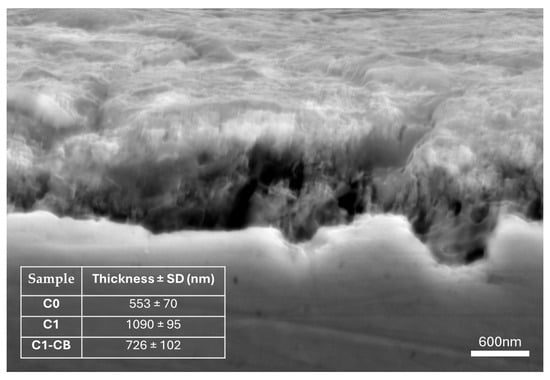
Figure 1.
Cross-sectional SEM image of sample C1.
As previously detailed, all coatings had the same deposition time. Then, the adjustment of pH allowed for an increase in the thickness of the coatings, which almost doubled, from 553 nm (C0) to 1090 nm (C1). The increase in pH leads to a greater availability of OH− ions in the electrolyte. This fact may promote the oxidation of H3PO3 and the reduction of nickel, resulting in higher deposition rates and, consequently, increased thickness.
On the other hand, sample C1-CB, which shares identical conditions to sample C1 except for the inclusion of CB nanoparticles, exhibits a notable reduction in thickness. This phenomenon has been previously documented within the domain of nanocomposite deposition and may become more pronounced with higher concentrations of nanoparticles [38].
The co-deposition of nanoparticles is governed by both chemical and physical phenomena within the electrolyte. These components undergo transport processes similar to other compounds, moving within ionic clouds (ions, water molecules, CB nanoparticles) that are directed toward the substrate. They diffuse through a boundary region near the substrate surface and eventually adsorb during the reduction of metal ions on the cathode’s surface [39]. However, as Protsenko and Danilov [40] highlight, the adsorption of dispersed particles onto a growing metal substrate is often irreversible due to the energy required to remove adsorption layers and solvate shells, which is essential for forming a strong adhesive bond. This irreversible adsorption can lead to steric hindrance, making it challenging for subsequent metal ions to access the surface, thereby impacting the deposition of nickel compounds and the overall coating growth rate. Indeed, the growth rate of sample C1-CB appears to be affected by the addition of these nanoparticles, as evidenced by the observed reduction in coating thickness.
3.1.2. SEM/EDS and Profilometric Analysis
The SEM micrographs of the samples, Figure 2, revealed similar surface morphology at different magnifications. At lower magnification, the surfaces appear homogenous and compact. Further magnification uncovers some irregularities, possibly related to wider superficial features, boundaries, and coating discontinuities. Figure 2f,i show these heterogeneities and the differences between the sample set, particularly C1 and C1-CB, which present more pronounced irregularities. This also suggests that these two samples have increased thickness, and the irregularities would be related to the coating’s growth, which could lead to an increase in unevenness.
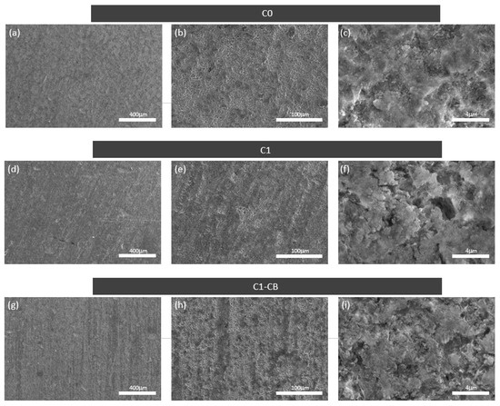
Figure 2.
Surface SEM micrographs, with different magnifications of sample C0, (a–c); C1, (d–f); C1-CB, (g–i).
The SEM-EDS mapping analysis of C0, Figure 3, shows the uniform presence of nickel and phosphorus across the coating’s surface. Similar patterns are found for the whole set.
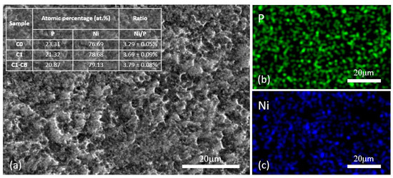
Figure 3.
SEM-EDS elemental mapping of sample C0, (a) surface SEM micrograph, (b) P elemental mapping, (c) Ni elemental mapping (inset: atomic percentages of Ni and P).
Moreover, the inset in Figure 3 illustrates the atomic percentages (at.%) of nickel and phosphorus for the samples, wherein the sample labeled C0 exhibits marginally higher phosphorus percentages as compared to C1 and C1-CB. This result confirms the influence of the pH on the phosphorus deposition process, with higher pH leading to lower phosphorus content. These findings align with the existing literature [41,42]. Furthermore, atomic percentages of phosphorus surpassing 17% (at.%) greatly indicate the amorphous nature of the coatings [43], which is to be confirmed in the XRD analysis. This phenomenon is due to the role of large amounts of phosphorus segregating on the substrate surface, which prevents the formation of the crystalline FCC nickel structure [44].
Figure 4 shows the 2D surface topography of the three coatings, which exhibit consistent features across the scanned regions, thereby confirming the uniformity of the coatings.
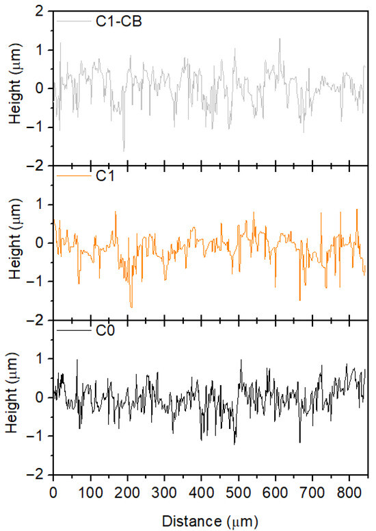
Figure 4.
Two-dimensional surface profiles of the coatings.
3.1.3. XRD
Figure 5 shows the XRD diffractograms of the samples, as well as the substrate. The XRD pattern of body centered cubic (BCC) iron is also displayed for comparison reasons (COD ID: 96-901-3473 [45]).
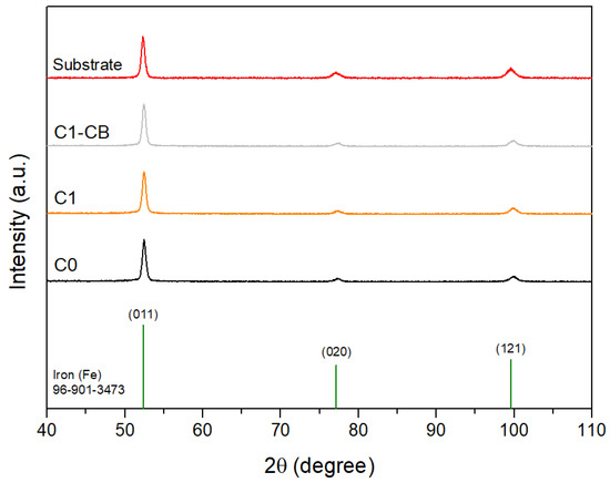
Figure 5.
XRD diffractograms of the samples, substrate, and stick pattern for reference BCC iron (COD ID: 96-901-3473).
Indeed, all the peaks can be assigned to those of the substrate and subsequently to the cubic iron reference. These results confirm the amorphous nature of the coatings, which was already suggested by the EDS results, being once again consistent with the literature. Moreover, the reduced sample thickness contributes to the presence of substrate peaks.
In addition, it should be noted that the detection of thin and poorly crystalline surface phases by grazing incidence XRD is inherently limited. Amorphous structures typically yield only broad halos with no distinct peaks, and very thin surface layers may remain below the detection threshold of the technique. Consequently, while the bulk of the coatings is confirmed to be amorphous, complementary vibrational spectroscopies (Raman and FTIR) are required to reveal hydroxide species such as Ni(OH)2 and NiOOH, as shown later.
3.1.4. Raman Spectroscopy
Through Raman analysis, compounds of the coating, amorphous and thus undetectable by XRD, were identified. Figure 6 displays the Raman spectra of the samples and the substrate, as well as the identified bands. The substrate band regions are delineated in the gray areas and allow the detection of Raman modes intrinsically related to the black coating (signaled with arrows).
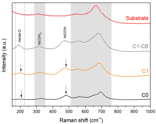
Figure 6.
Raman spectra of the substrate and black coatings (arrows indicate bands exclusive to the coatings).
The band at 200 cm−1 can be assigned to metal–O stretching vibrations, i.e., Ni–O and O–Ni–O [46,47]. It can be observed that the intensity of the peak increases for sample C1-CB, reflecting a larger proportion or better ordering of the oxide/hydroxide phases.
At around 320 cm−1, it is observable that the substrate band becomes more pronounced on the coatings spectra, suggesting that this band may be overlapped with a coating-related compound, particularly Ni(OH)2 [48].
The intrinsic coating band at 472 cm−1 can be assigned to stable NiOOH [49]. In addition, the band’s width suggests overlapping, confirmed by Ni(OH)2 modes, at 455 cm−1 for symmetric Ni-OH stretch, and 490 cm−1 for Ni-O stretch [50].
Therefore, the Raman spectroscopy data aligns with the established black nickel coating compositions reported in the literature. These may include the identified NiOOH and Ni(OH)2, but also other NiOx compounds and metallic Ni [13,48].
Furthermore, the results do not suggest the presence of active bands for any phosphorus compound, namely NiPO3 or NiPO2. However, the co-deposition of nickel and phosphorus is described in the literature in distinct ways, which are typically explained using two models: direct and indirect mechanisms. Both models represent the co-deposition as the reduction of Ni ions and phosphorus acid into elemental Ni and P, which in turn form the alloyed compounds of the coating. The strong interaction between nickel and phosphorus is considered the driving force behind the formation of these compounds [51].
The direct mechanism describes the phosphorus path with the partial reduction of phosphorus into hypophosphite, which is then reduced to elemental phosphorus, as shown in Equations (1) and (2), respectively. Still regarding the reactions near the substrate/electrolyte interface, this mechanism predicts the direct reduction of nickel and hydrogen ions, according to Equations (3) and (4), respectively [21,22,52,53].
H3PO3 + 2H+ + 2e− ⇌ H3PO2 + H2O
H3PO2 + H+ + e− ⇌ P + 2H2O
Ni2+ + 2e− → Ni0
2H+ + 2e− → H2
As for the indirect mechanism, it involves an intermediate during the phosphorus deposition, phosphine (PH3), which some authors have reported to be present in the electrolytes. Initially, the phosphorus acid is reduced to phosphine, according to Equation (5), and then it chemically reacts with the nickel ions, forming elemental Ni and P, as illustrated in Equation (6) [21,22,52,53].
H3PO3 + 6H0 → PH3 + 3H2O
2PH3 + 3Ni2+ → 3Ni0 + 2P0 + 6H+
However, neither of the models is consensual, due to the complex nature of nickel–phosphorus co-deposition, characterized by a multitude of factors that impact the process. The pH is one of the most well-known factors that deeply influence the deposition kinetics [54].
3.1.5. FTIR (Transmission Mode)
Figure 7 illustrates the FTIR spectrum of the samples, as well as the substrate for comparison purposes. All the coatings show two main bands that can be attributed to CO2 [55,56], at 2359 cm−1 and 2337 cm−1, a compound that may be a byproduct of chemical reactions on the electrolyte. Specifically, some studies reveal that when particular acidic and temperature conditions are met, sodium citrate (Na3C6H5O7) may undergo a decarboxylation process, releasing CO2 into the electrolyte [57]. These products may interfere with the surface of the forming coatings, affect their properties [57], and eventually be adsorbed.
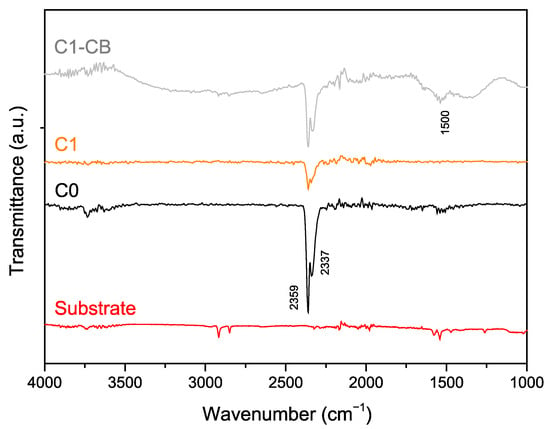
Figure 7.
FTIR (transmission mode) spectra of the substrate, C0, C1, and C1-CB samples.
Regarding this gas adsorption phenomenon, literature does not fully explain it within the framework of electroless deposition. As shown, thicker coatings seem to present weaker CO2 bands, with differences in band intensity suggesting that the CO2 adsorption may be linked to the interface between the substrate and the first layers of coating. Therefore, as the coating develops, becoming denser and more continuous, the contribution of initially adsorbed CO2 diminishes, leading to a reduction in band intensity.
It is also crucial to notice the large band in C1-CB, centered at around 1500 cm−1, which is characteristic of CB nanoparticles [58,59]. This band confirms the presence and successful incorporation of CB nanoparticles in the deposited coating.
3.1.6. Reflectivity and Color Coordinates
The analysis of the CIE L*a*b* color coordinates disclosed not only the degree of darkness of the samples, but also their hues, Figure 8a. The degree of darkness of a surface can be quantified according to its brightness (L*), ranging from absolute darkness at 0 to absolute whiteness at 100, with values below 40 being considered visually dark by human perception [60,61,62]. Table 2 shows the brightness values for each sample, namely the darkest, C1, and the brightest, C0. The incorporation of nanoparticles seems to introduce some heterogeneity in the brightness results. However, these are still competing and similar to the other samples. Concerning color coordinates, the entire dataset falls within the quadrant of yellow and red hues. Adjusting the pH of sample C1 resulted in less saturated hues, closer to the graph’s center. Conversely, sample C0 counterparts with higher-saturation hues. Figure 8b shows the optical images of the samples.
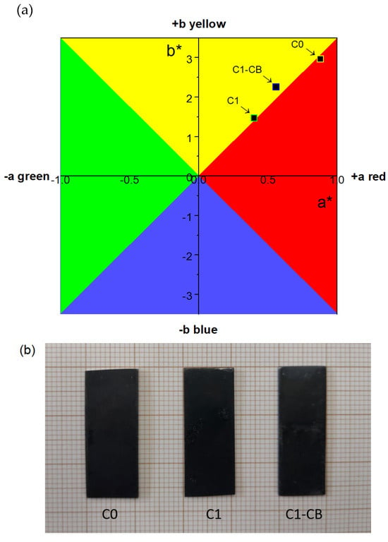
Figure 8.
(a) CIE L*a*b* color diagram of the black coatings; (b) Optical images of C0, C1, and C1-CB samples.

Table 2.
Brightness values, L*.
Figure 9 plots the black coatings’ total and diffuse reflectivity curves (C0, C1, and C1-CB) against wavelength, in the UV-visible range. Reflection on the surface can occur through two mechanisms: specular reflection and diffuse reflection, which constitute total reflection.
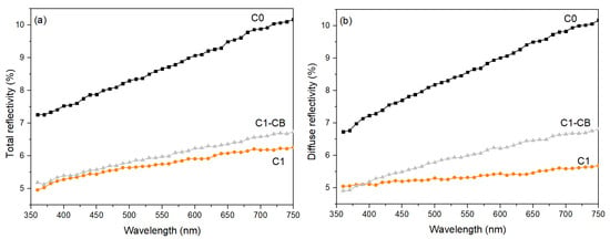
Figure 9.
Reflectivity spectra of the black coatings, (a) total reflectivity, and (b) diffuse reflectivity.
Regarding total reflectivity, the sample with intrinsic pH (C0) exhibits the highest values across all wavelengths. Conversely, the sample with adjusted pH (C1) has lower total reflectivity overall. Concerning the sample with incorporated CB nanoparticles (C1-CB), the reflectivity values are slightly higher than those of C1 but are similar at shorter wavelengths. Indeed, all curves are wavelength-dependent.
Regarding diffuse reflectivity, sample C0 exhibits the highest values, while sample C1 exhibits the lowest ones, with an almost wavelength-independent trend. Overall, all samples show an increase in reflectivity values at longer wavelengths.
Reflectivity may influence the perception of the color of a surface, but it is not adequate for proper color characterization on its own.
3.1.7. Absorptance and Emissivity
The potential of a material to harness energy from solar radiation may be determined by the estimation of its absorptance (α) and emissivity (ε) values. In short, bodies may absorb part of the incident light that reaches the surface; however, this energy may also be re-emitted. Therefore, the coatings must absorb the radiation as much as possible (higher absorptance) while having the ability to retain that energy (lower emissivity) for subsequent use.
That being said, Figure 10a shows the terrestrial direct normal solar spectral irradiance for air mass 1.5 and α(λ) × Psun(λ) as a function of radiation wavelength and Figure 10b the reflectance measurements in the UV, visible, and near-IR range, as well as the absorptance values, α, for each sample (in the inset). In fact, Kirchhoff’s law allows the correlation between the spectral absorptance α(λ) and the total reflectance R(λ) of an opaque material: α(λ) = 1 − R(λ) [63].
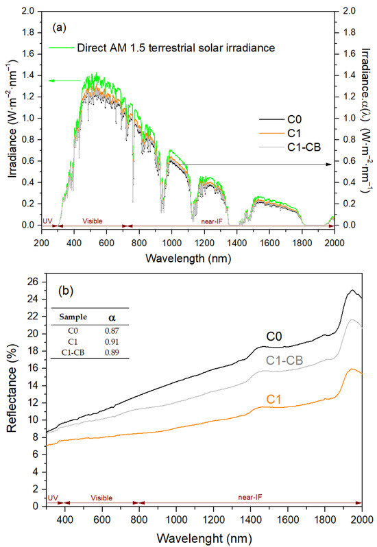
Figure 10.
(a) Terrestrial direct normal solar spectral irradiance for air mass 1.5 and α(λ) × Psun(λ) as a function of radiation wavelength; (b) Total reflectance of the black coatings as a function of radiation wavelength (inset: total absorptance).
Particularly, the absorptance was estimated with Equation (7), with integration limits set from 280 nm to 2000 nm, which is based on the overlap between the absorptance spectrum of the samples and the solar spectrum [48,63], where Psun (λ) is defined as the normal solar spectral irradiance by ISO standard 9845-1:2022 for air mass (AM) 1.5 [64].
The samples exhibited reduced reflectance within the short-wavelength region, with an increase noted towards the longer wavelengths of the spectrum. Namely, there are two main bands in the near-IR region, at around 1450 nm and 1950 nm. The sample with CB nanoparticles (C1-CB) has a decrease in reflectance when compared with the initial pH intrinsic sample (C0). However, C1, which has increased and adjusted pH, presents the lowest reflectance values, leading to the best total absorptance value α: 0.91.
The samples’ emissivity, ε, was determined through FTIR-R analysis across the infrared spectrum, illustrated in Figure 11. Particularly, this property may be calculated with Equation (8), with integration limits set from 2500 nm to 25,000 nm, where PB (λ) represents the spectral radiance of a black-body, defined by Planck’s law, at a given temperature (in the present case, room temperature) [48,65]. So, Equation (9) expresses PB (λ), where C1 = 3.743 × 10⁻¹⁶ Wm2 and C2 = 1.4387 × 10⁻² mK [48,65]. This time, the pH adjustment led to an undesirable increase in emissivity (C1), while its CB-doped counterpart (C1-CB) slightly enhanced this value to 0.06.
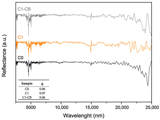
Figure 11.
FTIR (reflectance mode) of the samples, as a function of the radiation wavelength (inset: total emissivity).
As explained earlier, the energy conversion potential of the coatings is dependent on the balance between high absorptance and low emissivity and is most often evaluated using the figure of merit, α − ε. Table 3 systematizes the figure of merit for the samples, and the best results are attributed to sample C1. The differences between the set of samples are not disruptive, although the addition of CB nanoparticles does not seem to greatly affect the overall figure of merit.

Table 3.
Figure of merit α − ε of samples as deposited.
3.2. Evaluation of Morphological and Optical Stability Under Aging Conditions
An aging study was conducted to determine the behavior of the samples when subject to heat for longer periods. The primary objective is to evaluate the coatings’ stability and ensure the preservation of their integrity and optical properties. Particularly, the set of samples was tested at 200 °C for a period of 12 h and a heating rate of 5 °C/min.
This regime was chosen to investigate the early-stage structural and microstructural evolution of the Ni-P coatings under moderate thermal stress, rather than complete crystallization or phase transformation, which typically occur at higher temperatures (300–400 °C). At 200 °C, subtle changes such as relaxation of internal stresses, slight densification, and initial precipitation of Ni3P or other nanoscale phases are expected, which can influence the surface morphology of the coating and, consequently, its reflectance and emittance. This protocol is representative of realistic operating conditions for applications where the coating may experience prolonged exposure to moderately elevated temperatures, allowing assessment of potential property changes without reaching full crystallization [66,67,68].
The SEM/EDS analysis did not show any substantial differences, namely different phosphorus content, signs of corrosion, cracks, or distinct morphology. Figure 12 illustrates the SEM micrographs of C0 surface as deposited (Figure 12a) and after (Figure 12b) the aging procedure.
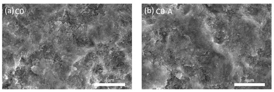
Figure 12.
Surface SEM micrographs of sample C0, (a) as deposited, (b) after aging.
As expected, no changes regarding the amorphous nature of the coatings, nor new phases, were detected in the Raman and XRD analyses. According to Duncan [53], the deposited alloyed Ni-P coatings are not in an equilibrium state without heat-treatment, and are composed of two different metastable phases, β and/or γ (amorphous). For the specific case of high phosphorus content coatings, as the ones studied here, heat-treatments within the range 330–360 °C promote the decomposition of the metastable phase (γ) into the crystalline phases, α and Ni3P [69]. Other authors confirm the formation of new phases and morphology changes at temperatures above 300 °C, with a consensus of complete crystallinity above 400 °C [70,71,72,73].
Finally, the aging process induced an increase in emissivity (ε) of the coatings, translating into lower figures of merit and overall lower performance than the as-deposited counterparts, Table 4. Nevertheless, the aged coatings exhibit optical properties that remain competitive with those documented in the literature, particularly when considering additional factors such as the absence of cracks and pinholes.

Table 4.
Figure of merit α − ε of samples as deposited and after aging.
The use of electroless nickel coatings, specifically aimed at solar–thermal energy conversion, is not extensively documented in the literature. However, existing literature focuses on electroless Ni-P solutions, which vary in electrolyte composition and yield distinctive alloy coatings. The development of composite solutions that do not need pre-coatings or blackening processes after deposition remains insufficiently studied.
In that regard, available solutions heavily rely on blackening and/or etching processes that are carried on after the deposition of bright nickel coatings, resorting to their immersion in acid solutions [16,74,75,76]. The additional steps involve thicker coatings (for adequate etching), higher deposition times (several hours), and great industrial intricacy [16,76]. The added complexity of the global process cannot be ignored when communities rightfully demand manufacturable and straightforward solutions that can merge with the real world. Furthermore, the majority of cited works employ elevated temperature parameters (approximating 90 °C), while neglecting the evaluation of emissivity and the impact of coating aging.
The figure of merit of the coatings before and after aging, as well as the values in the literature for electroless nickel solutions, are presented in Table 5 for comparison purposes. Even after aging, the coatings preserve their optical performance when compared to the references, with sample C1 showing the best results. As for C0 and C1-CB, their figure of merit is lower when aged, but still within the α − ε range of other studies.

Table 5.
Figure of merit α − ε of samples as deposited, after aging, and the literature values.
Nevertheless, the side comparison of these results and those found in the literature must not be limited to their figure of merit but must encompass other factors that are also crucial for assessing their overall performance.
4. Conclusions
The present study led to the successful deposition of electroless nickel–phosphorus coatings, with high potential for solar absorption applications. This translates as pinhole and crack-free coatings that have good adhesion and enhanced optical properties.
The SEM-EDS analysis showed crack-free, homogenous, and compact surfaces, with uniform distributions of nickel and phosphorus. The increase in pH led to lower phosphorus content. In fact, all coatings are above 17 at.% of phosphorus, which indicates their amorphous nature, confirmed in the XRD analysis.
As expected, the pH has a great influence on deposition rates, and higher pH values lead to higher thickness. A reduction in thickness was observed with the addition of CB nanoparticles, which may be attributed to their impact on the metal ions’ access to the coating surface.
The FTIR and Raman spectra allowed us to confirm the successful incorporation of CB nanoparticles, as well as to disclose the composition of the coatings, respectively. Particularly, compounds such as Ni(OH)2 and NiOOH are believed to form the amorphous coatings.
The reflectivity and brightness results of sample C1 were the best, with the lowest brightness (L*) value, being the closest to absolute black. The addition of CB nanoparticles introduced some heterogeneity in the brightness values.
All the coatings demonstrated promising solar absorption performance through competitive figures of merit (α − ε). Again, the sample with the highest pH (C1) presented the highest figure of merit, 0.84. The aging process of the coatings proved their resilience, especially for sample C1, which seems to have the overall best results.
Indeed, all the coatings have competitive values when compared with the solutions found in the literature. This is particularly relevant for sample C1-CB, which has incorporated CB nanoparticles that do not actively contribute to the enhancement of the absorptance or emissivity but lead to favorable results.
Author Contributions
Conceptualization, G.S. and S.D.; methodology, G.S. and S.D.; validation, G.S. and S.D.; formal analysis, G.S.; investigation, G.S., D.C., S.G., Z.B. and A.C.; resources, M.L. and S.C.; data curation, G.S.; writing—original draft preparation, G.S.; writing—review and editing, G.S., D.C., S.G., Z.B., M.L., A.C., S.C. and S.D.; visualization, G.S.; supervision, S.C. and S.D.; project administration, S.C.; funding acquisition, S.C. All authors have read and agreed to the published version of the manuscript.
Funding
This research is sponsored by National Funds through FCT—Fundação para a Ciência e Tecnologia—under projects UIDB/00285—Centre for Mechanical Engineering, Materials and Processes—and LA/P/0112/2020, and by FEDER Funds through the COMPETE 2020 Program and National Funds through the FCT—Portuguese Foundation for Science and Technology under the projects LISBOA-01-0247-FEDER-039985/POCI-01-0247-FEDER-039985, LA/P/0037/2020, UIDP/50025/2020, and UIDB/50025/2020 of the Associate Laboratory Institute of Nanostructures, Nanomodelling and Nanofabrication—i3N. Also, this research was financed by the PRR—Recovery and Resilience Plan—and by Next-Generation EU Funds, following NOTICE No. 02/C05-i01/2022, Component 5—Capitalization and Business Innovation—Mobilizing Agendas for Business Innovation under the AM2R project “Mobilizing Agenda for business innovation in the Two Wheels sector” (reference: 7253).
Data Availability Statement
The original contributions presented in this study are included in the article. Further inquiries can be directed to the corresponding authors.
Conflicts of Interest
Author Mariana Lopes was employed by the company SRAMPORT Lda.. The authors declare that the research was conducted in the absence of any commercial or financial relationships that could be construed as a potential conflict of interest.
References
- NASA. Education Overview. Available online: https://Ceres.Larc.Nasa.Gov/News/Education-Overview/#additional-Energy-Budget-Resources (accessed on 18 December 2024).
- Tian, Y.; Zhao, C.Y. A review of solar collectors and thermal energy storage in solar thermal applications. Appl. Energy 2013, 104, 538–553. [Google Scholar] [CrossRef]
- Smil, V. General Energetics: Energy in the Biosphere and Civilization, 1st ed.; Wiley: New York, NY, USA, 1991. [Google Scholar]
- Zhao, J.; Lai, H.; Li, M. Anchoring 1T-MoS2 Petals on N-Doped Reduced Graphene Oxide for Exceptional Electromagnetic Wave Absorption. Int. J. Miner. Metall. Mater. 2025, 32, 619–630. [Google Scholar] [CrossRef]
- Hu, H.; Chen, F.; Li, Y.; Li, J.; Cui, L.; Jiang, D.; Lin, X.; Gao, J. Construction of Graphene Supported TiO2 Nanosheet Array/CdS/Ni2P Composite with Dual Heterojunctions for Boosting Photocatalytic Hydrogen Evolution. J. Alloys Compd. 2025, 1024, 180216. [Google Scholar] [CrossRef]
- Liu, Y.; Liu, M.; Yang, H.; Yi, Z.; Zhang, H.; Tang, C.; Deng, J.; Wang, J.; Li, B. Photoelectric Simulation of Perovskite Solar Cells Based on Two Inverted Pyramid Structures. Phys. Lett. A 2025, 552, 130653. [Google Scholar] [CrossRef]
- Yuan, Y.; Liu, H.; Liu, M.; Zhang, W.; Li, X.; Cheng, S. Design of wide-angle broadband titanium-nitride solar absorber based on column-cavity structure. Phys. Lett. A 2025, 556, 130832. [Google Scholar] [CrossRef]
- FAO. Progress on the Level of Water Stress—Mid-Term Status of SDG Indicator 6.4.2 and Acceleration Needs, with Special Focus on Food Security; Food and Agriculture Organization (FAO): Rome, Italy, 2024; Available online: https://openknowledge.fao.org/handle/20.500.14283/cd2179en (accessed on 18 December 2024).
- IEA. World Energy Outlook 2024; IEA: Paris, France, 2024; Available online: https://www.iea.org/reports/world-energy-outlook-2024 (accessed on 18 December 2024).
- Alshukri, M.J.; Kadhim Hussein, A.; Eidan, A.A.; Alsabery, A.I. A review on applications and techniques of improving the performance of heat pipe-solar collector systems. Sol. Energy 2022, 236, 417–433. [Google Scholar] [CrossRef]
- Suman, S.; Khan, M.K.; Pathak, M. Performance enhancement of solar collectors—A review. Renew. Sustain. Energy Rev. 2015, 49, 192–210. [Google Scholar] [CrossRef]
- Duffie, J.A.; Beckman, W.A.; Blair, N. Solar Engineering of Thermal Processes, Photovoltaics and Wind, 5th ed.; John Wiley & Sons, Inc.: Hoboken, NJ, USA, 2020. [Google Scholar]
- Lizama-Tzec, F.I.; Macías, J.D.; Estrella-Gutiérrez, M.A.; Cahue-López, A.C.; Arés, O.; de Coss, R.; Alvarado-Gil, J.J.; Oskam, G. Electrodeposition and characterization of nanostructured black nickel selective absorber coatings for solar–thermal energy conversion. J. Mater. Sci. Mater. Electron. 2015, 26, 5553–5561. [Google Scholar] [CrossRef]
- Kadırgan, F. Electrochemical nano-coating processes in solar energy systems. Int. J. Photoenergy 2006, 2006, 084891. [Google Scholar] [CrossRef]
- Elsener, B.; Crobu, M.; Scorciapino, M.A.; Rossi, A. Electroless deposited Ni–P alloys: Corrosion resistance mechanism. J. Appl. Electrochem. 2008, 38, 1053–1060. [Google Scholar] [CrossRef]
- John, S.; Shanmugam, N.V.; Srinivasan, K.N.; Selvam, M.; Shenoi, B.A. Blackening of electroless nickel deposits for solar energy applications. Surf. Technol. 1983, 20, 331–338. [Google Scholar] [CrossRef]
- Davis, J.R. (Ed.) Surface Engineering for Corrosion and Wear Resistance, 1st ed.; ASM International: Materials Park, OH, USA, 2001. [Google Scholar]
- Alghoul, M.A.; Sulaiman, M.Y.; Azmi, B.Z.; Wahab, M.A. Review of materials for solar thermal collectors. Anti-Corros. Methods Mater. 2005, 52, 199–206. [Google Scholar] [CrossRef]
- Katz, S.A.; Salem, H. The toxicology of chromium with respect to its chemical speciation: A review. J. Appl. Toxicol. 1993, 13, 217–224. [Google Scholar] [CrossRef] [PubMed]
- Saha, R.; Nandi, R.; Saha, B. Sources and toxicity of hexavalent chromium. J. Coord. Chem. 2011, 64, 1782–1806. [Google Scholar] [CrossRef]
- Agarwala, R.C.; Agarwala, V.; Sharma, R. Electroless Ni-P Based Nanocoating Technology—A Review. Synth. React. Inorg. Met.-Org. Nano-Met. Chem. 2006, 36, 493–515. [Google Scholar] [CrossRef]
- Krishnan, K.H.; John, S.; Srinivasan, K.N.; Praveen, J.; Ganesan, M.; Kavimani, P.M. An overall aspect of electroless Ni-P depositions—A review article. Metall. Mater. Trans. A 2006, 37, 1917–1926. [Google Scholar] [CrossRef]
- Sorahan, T.; Burges, D.C.; Hamilton, L.; Harrington, J.M. Lung cancer mortality in nickel/chromium platers, 1946–1995. Occup. Environ. Med. 1998, 55, 236–242. [Google Scholar] [CrossRef]
- Khollari, M.A.R.; Ghorbani, M.; Afshar, A. Fabrication and characterization of TiO2 deposited black electroless Ni-P solar absorber. Appl. Surf. Sci. 2019, 496, 143632. [Google Scholar] [CrossRef]
- Wang, P.; Cheng, Y.; Zhang, Z. A study on the electrocodeposition processes and properties of Ni–SiC nanocomposite coatings. J. Coat. Technol. Res. 2011, 8, 409–417. [Google Scholar] [CrossRef]
- Wielage, B.; Lampke, T.; Zacher, M.; Dietrich, D. Electroplated Nickel Composites with Micron- to Nano-Sized Particles. Key Eng. Mater. 2008, 384, 283–309. [Google Scholar] [CrossRef]
- Garcia, I.; Fransaer, J.; Celis, J.-P. Electrodeposition and sliding wear resistance of nickel composite coatings containing micron and submicron SiC particles. Surf. Coat. Technol. 2001, 148, 171–178. [Google Scholar] [CrossRef]
- Deng, Z.; Liu, P.-F.; Zhou, J.; Miao, L.; Peng, Y.; Su, H.; Wang, P.; Wang, X.; Cao, W.; Jiang, F.; et al. A Novel Ink-Stained Paper for Solar Heavy Metal Treatment and Desalination. Sol. RRL 2018, 2, 1800073. [Google Scholar] [CrossRef]
- Liu, B.; Wang, C.; Bazri, S.; Badruddin, I.A.; Orooji, Y.; Saeidi, S.; Wongwises, S.; Mahian, O. Optical properties and thermal stability evaluation of solar absorbers enhanced by nanostructured selective coating films. Powder Technol. 2021, 377, 939–957. [Google Scholar] [CrossRef]
- Mallory, G.O.; Hajdu, J.B. (Eds.) Electroless Plating: Fundamentals and Applications, 3rd ed.; Cambridge University Press: Cambridge, UK, 1990. [Google Scholar]
- Hu, C.-C.; Bai, A. Composition Control of Electroplated Nickel–Phosphorus Deposits. Surf. Coat. Technol. 2001, 137, 181–187. [Google Scholar] [CrossRef]
- Huang, G.-F.; Huang, W.-Q.; Wang, L.-L.; Zou, B.-S.; Chen, D.-P.; Li, D.-Y.; Wei, J.-M.; Zhang, J.-H. Effects of Complexing Agents on the Corrosion Resistance of Electroless Ni-Fe-P Alloys. Int. J. Electrochem. Sci. 2007, 2, 321–328. [Google Scholar] [CrossRef]
- Yan, W.; Tiejun, C.; Ruihong, Z. Electroless Deposition of NiMoP Coating on Q235B Steel and Its Corrosion Resistance in Simulated Concrete Pore Solution. Int. J. Electrochem. Sci. 2023, 18, 100313. [Google Scholar] [CrossRef]
- Nickel Institute. Nickel Plating Handbook; Nickel Institute: Toronto, ON, Canada, 2022. [Google Scholar]
- Devesa, S.; Cavaleiro, D.; Santo, D.; Gavinho, S.; Cunha, A.F.; Santos, P.; Carvalho, S. Boric Acid-Free Electrodeposition Process and Solar–Thermal Energy Conversion of and Ni-Carbon Black Nanocomposite Coatings. J. Mater. Res. 2024, 39, 3397–3410. [Google Scholar] [CrossRef]
- Devesa, S.; Santos, G.; Cavaleiro, D.; Lopes, M.; Ramos, A.S.; Carvalho, S. A Comprehensive Investigation of Boric Acid-Free Electrodeposition of Ni-P Alloy on Steel. Colloids Surf. A Physicochem. Eng. Asp. 2025, 705, 135678. [Google Scholar] [CrossRef]
- Devesa, S.; Benzarti, Z.; Santos, G.; Cavaleiro, D.; Cunha, A.; Santos, J.; Carvalho, S. Enhancing Solar Absorption with Double-Layered Nickel Coatings and WS2 Nanoparticles on Copper Substrates. Energies 2024, 17, 3869. [Google Scholar] [CrossRef]
- Nasirpouri, F. Electrodeposition of Nanostructured Materials, 1st ed.; Springer Series in Surface Sciences; Springer: Cham, Switzerland, 2016; Volume 66. [Google Scholar] [CrossRef]
- Low, C.T.J.; Wills, R.G.A.; Walsh, F.C. Electrodeposition of composite coatings containing nanoparticles in a metal deposit. Surf. Coat. Technol. 2006, 201, 371–383. [Google Scholar] [CrossRef]
- Protsenko, V.S.; Danilov, F.I. Kinetic Model of Composite Coatings Electrodeposition Assuming Irreversible Adsorption of Dispersed Particles on a Growing Metal Substrate. J. Electroanal. Chem. 2022, 918, 116463. [Google Scholar] [CrossRef]
- Kollabathini, S.V.S.S.C.; Dora, S.P.; Chintada, S.; Arava, H. Influence of pH on the electroless Ni-P plating of SiC particles. Surf. Eng. 2025, 41, 217–226. [Google Scholar] [CrossRef]
- Tian, M.; Jian, Z.; Chang, F.; Hai, R. Properties of electroless thick nickel–phosphorus coating on SiCp/Al composite surface in acidic conditions. J. Mater. Sci. 2023, 58, 1886–1904. [Google Scholar] [CrossRef]
- Cotell, C.M.; Sprague, J.A.; Smidt, F.A., Jr. ASM Handbook, Volume 5: Surface Engineering; ASM International: Materials Park, OH, USA, 1994; ISBN 978-0-87170-384-2. [Google Scholar]
- Balaraju, J.N.; Narayanan, T.S.N.S.; Seshadri, S.K. Structure and phase transformation behaviour of electroless Ni–P composite coatings. Mater. Res. Bull. 2006, 41, 847–860. [Google Scholar] [CrossRef]
- Basinski, Z.S.; Hume-Rothery, W.; Sutton, A.L. The lattice expansion of iron. Proc. R. Soc. Lond. Ser. Math. Phys. Sci. 1997, 229, 459–467. [Google Scholar] [CrossRef]
- Padmanathan, N.; Shao, H.; Razeeb, K.M. Multifunctional Nickel Phosphate Nano/Microflakes 3D Electrode for Electrochemical Energy Storage, Nonenzymatic Glucose, and Sweat pH Sensors. ACS Appl. Mater. Interfaces 2018, 10, 8599–8610. [Google Scholar] [CrossRef]
- Zhao, Z.; Liu, Y.; Yi, W.; Wang, H.; Liu, Z.; Yang, J.; Zhang, M. Sheeted NiCo Double Phosphate In Situ Grown on Nickel Foam Toward Bifunctional Water and Urea Oxidation. Electrocatalysis 2023, 14, 247–258. [Google Scholar] [CrossRef]
- Estrella-Gutiérrez, M.A.; Lizama-Tzec, F.I.; Arés-Muzio, O.; Oskam, G. Influence of a metallic nickel interlayer on the performance of solar absorber coatings based on black nickel electrodeposited onto copper. Electrochim. Acta 2016, 213, 460–468. [Google Scholar] [CrossRef]
- Yan, Y.; Wang, R.; Zheng, Q.; Zhong, J.; Hao, W.; Yan, S.; Zou, Z. Nonredox trivalent nickel catalyzing nucleophilic electrooxidation of organics. Nat. Commun. 2023, 14, 7987. [Google Scholar] [CrossRef]
- Lo, Y.L.; Hwang, B.J. In Situ Raman Studies on Cathodically Deposited Nickel Hydroxide Films and Electroless Ni−P Electrodes in 1 M KOH Solution. Langmuir 1998, 14, 944–950. [Google Scholar] [CrossRef]
- Morikawa, T.; Nakade, T.; Yokoi, M.; Fukumoto, Y.; Iwakura, C. Electrodeposition of Ni-P alloys from Ni-citrate bath. Electrochim. Acta 1997, 42, 115–118. [Google Scholar] [CrossRef]
- Lelevic, A. Ni-P coatings electroplating-A review, Part I: Pure Ni-P alloy. arXiv 2018, arXiv:1807.04693. [Google Scholar]
- Daly, B.P.; Barry, F.J. Electrochemical nickel–phosphorus alloy formation. Int. Mater. Rev. 2003, 48, 326–338. [Google Scholar] [CrossRef]
- Ordine, A.P.; Díaz, S.L.; Margarit, I.C.P.; Barcia, O.E.; Mattos, O.R. Electrochemical study on Ni–P electrodeposition. Electrochem. Impedance Spectrosc. 2006, 51, 1480–1486. [Google Scholar] [CrossRef]
- Yang, J.; Solomatin, N.; Kraytsberg, A.; Ein-Eli, Y. In-Situ Spectro–electrochemical Insight Revealing Distinctive Silicon Anode Solid Electrolyte Interphase Formation in a Lithium–ion Battery. ChemistrySelect 2016, 1, 572–576. [Google Scholar] [CrossRef]
- Kumar, R.; Lang, S.; Englezos, P.; Ripmeester, J. Application of the ATR-IR Spectroscopic Technique to the Characterization of Hydrates Formed by CO2, CO2/H2 and CO2/H2/C3H8. J. Phys. Chem. A 2009, 113, 6308–6313. [Google Scholar] [CrossRef]
- Berkh, O.; Burstein, L.; Shacham-Diamand, Y.; Gileadi, E. The Chemical and Electrochemical Activity of Citrate on Pt Electrodes. J. Electrochem. Soc. 2011, 158, F85. [Google Scholar] [CrossRef]
- Zappielo, C.D.; Nanicuacua, D.M.; dos Santos, W.N.L.; da Silva, D.L.F.; Dall’ANtônia, L.H.; de Oliveira, F.M.; Clausen, D.N.; Tarley, C.R.T. Solid Phase Extraction to On-Line Preconcentrate Trace Cadmium Using Chemically Modified Nano-Carbon Black with 3-Mercaptopropyltrimethoxysilane. J. Braz. Chem. Soc. 2016, 27, 1715–1726. [Google Scholar] [CrossRef]
- Jaberi Mofrad, F.; Ostad Movahed, S.; Ahmadpour, A. Surface modification of commercial carbon black by silane coupling agents for improving dispersibility in rubber compounds. J. Appl. Polym. Sci. 2024, 141, e55155. [Google Scholar] [CrossRef]
- Ponte, F.; Sharma, P.; Figueiredo, N.M.; Ferreira, J.; Carvalho, S. Decorative Chromium Coatings on Polycarbonate Substrate for the Automotive Industry. Materials 2023, 16, 2315. [Google Scholar] [CrossRef]
- Carneiro, E.; Parreira, N.M.G.; Vuchkov, T.; Cavaleiro, A.; Ferreira, J.; Andritschky, M.; Carvalho, S. Cr-Based Sputtered Decorative Coatings for Automotive Industry. Materials 2021, 14, 5527. [Google Scholar] [CrossRef]
- Brown, R.J.C.; Brewer, P.J.; Milton, M.J.T. The physical and chemical properties of electroless nickel–phosphorus alloys and low reflectance nickel–phosphorus black surfaces. J. Mater. Chem. 2002, 12, 2749–2754. [Google Scholar] [CrossRef]
- Kennedy, C.E. Review of Mid- to High-Temperature Solar Selective Absorber Materials; National Renewable Energy Lab (NREL): Golden, CO, USA, 2002. [Google Scholar]
- ISO 9845-1:2022; Solar Energy—Reference Solar Spectral Irradiance at the Ground at Different Receiving Conditions—Part 1: Direct Normal and Hemispherical Solar Irradiance for Air Mass 1.5. ISO: Geneva, Switzerland, 2022.
- Ienei, E.; Milea, A.C.; Duta, A. Influence of Spray Pyrolysis Deposition Parameters on the Optical Properties of Porous Alumina Films. Energy Procedia 2014, 48, 97–104. [Google Scholar] [CrossRef]
- Winowlin Jappes, J.T.; Brintha, N.C.; Adam Khan, M. Influence of Heat Treatment over Electroless Crystallinity of Electroless Nickel Deposition. Mater. Today Proc. 2021, 46, 7230–7235. [Google Scholar] [CrossRef]
- Buchtík, M.; Doskočil, L.; Brescher, R.; Doležal, P.; Másilko, J.; Wasserbauer, J. The Effect of Crystallization and Phase Transformation on the Mechanical and Electrochemical Corrosion Properties of Ni-P Coatings. Coatings 2021, 11, 447. [Google Scholar] [CrossRef]
- Zhao, G.; Zou, Y.; Zhang, H.; Zou, Z. Effect of Low-Temperature Annealing on The Properties of Ni-P Amorphous Alloys Deposited Via Electroless Plating. Arch. Metall. Mater. 2015, 60, 865–869. [Google Scholar] [CrossRef]
- Duncan, R. The metallurgical structure of electroless nickel deposits: Effect on coating properties. Plat. Surf. Finish. 1996, 83, 65–69. [Google Scholar]
- Karthikeyan, S.; Vijayaraghavan, L. Investigation of the surface properties of heat treated electroless Ni–P coating. Trans. IMF 2016, 94, 265–273. [Google Scholar] [CrossRef]
- Buchtík, M.; Krystýnová, M.; Másilko, J.; Wasserbauer, J. The Effect of Heat Treatment on Properties of Ni–P Coatings Deposited on a AZ91 Magnesium Alloy. Coatings 2019, 9, 461. [Google Scholar] [CrossRef]
- Ashassi-Sorkhabi, H.; Rafizadeh, S.H. Effect of coating time and heat treatment on structures and corrosion characteristics of electroless Ni–P alloy deposits. Surf. Coat. Technol. 2004, 176, 318–326. [Google Scholar] [CrossRef]
- Sampath Kumar, P.; Kesavan Nair, P. Studies on crystallization of electroless Ni–P deposits. Int. Conf. Adv. Mater. Process. Technol. 1996, 56, 511–520. [Google Scholar] [CrossRef]
- Bagheri, M.; Ashrafizadeh, F.; Najafabadi, M.H. Black Nickel Coating and Color Anodized Layers for Solar Absorber. Trans. Indian Inst. Met. 2014, 67, 927–934. [Google Scholar] [CrossRef]
- Ashrafizadeh, F.; Bagheri, M.; Hosseini, M. A comparative study on optical properties of black nickel coatings and color anodizing for solar absorber. In Optical Interference Coatings; Tilsch, M., Driggers, R., Eds.; Optica Publishing Group: Whistler, BC, Canada, 2013; p. MC.3. [Google Scholar]
- Azli, N.N.A.; Mohd Amin, N.F.; Oluhende, S.T.; Mohamad, S.N.A.; Fadil, N.A. Electroless deposited black nickel-phosphorous solar absorber coatings on carbon steel: Effect of plating bath pH. Mater. Today Proc. 2021, 39, 1071–1076. [Google Scholar] [CrossRef]
- Papini, M.; Papini, F. Study and realization of a selective absorber Ni-P compound for the photothermal conversion of solar radiation. Thin Solid Film. 1984, 115, 1–11. [Google Scholar] [CrossRef]
Disclaimer/Publisher’s Note: The statements, opinions and data contained in all publications are solely those of the individual author(s) and contributor(s) and not of MDPI and/or the editor(s). MDPI and/or the editor(s) disclaim responsibility for any injury to people or property resulting from any ideas, methods, instructions or products referred to in the content. |
© 2025 by the authors. Licensee MDPI, Basel, Switzerland. This article is an open access article distributed under the terms and conditions of the Creative Commons Attribution (CC BY) license (https://creativecommons.org/licenses/by/4.0/).