Article

Evaluation of the Reinforcing Effect of Intermetallic and Ceramic Phases in a WE54-15%(Vol.%)SiCw Composite Using In Situ Synchrotron Radiation Diffraction

Department of Physical Metallurgy, National Centre for Metallurgical Research CENIM-CSIC, Avda. Gregorio del Amo 8, 28040 Madrid, Spain
*
Author to whom correspondence should be addressed.
J. Compos. Sci. 2025, 9(1), 46; https://doi.org/10.3390/jcs9010046
Submission received: 30 October 2024 / Revised: 2 January 2025 / Accepted: 14 January 2025 / Published: 18 January 2025
(This article belongs to the Section Composites Modelling and Characterization)

Abstract

:
The reinforcing effect of β-Mg14YNd2 precipitates and SiC whiskers has been evaluated in a WE54-15%(vol.%)SiCw composite using synchrotron radiation diffraction during compression tests from room temperature to 300 °C. The addition of SiC whiskers slightly increases the yield stress compared to an unreinforced WE54 alloy. However, whiskers are not effective in increasing the temperature at which the mechanical strength of the unreinforced WE54 alloy begins to decay. The plastic deformation process is controlled by the magnesium matrix over the entire compression temperature range. On one hand, β-Mg14YNd2 precipitates assume an additional transferred load from the magnesium matrix just after the yield point in both the WE54 alloy and WE54-15%SiCw composite. The magnitude of transferred load becomes smaller as the temperature increases due to the relaxation process around precipitates. On the other hand, the reinforcing effect of SiC whiskers is greater than that of β-Mg14YNd2 precipitates, although its effect also tends to disappear at temperatures equal to or higher than 200 °C.

1. Introduction

Magnesium alloys exhibit the potentiality for their use as structural materials in applications where weight reduction is a fundamental aspect. The low density of magnesium induces a high specific strength of the alloys. However, magnesium alloys have some limitations that have restricted their use in the automobile and aerospace industries. From the mechanical point of view, their mechanical strength is low and decrease rapidly at temperatures above room temperature. Moreover, their poor creep resistance dissuades their use in applications where temperature exceeds 200 °C.
The additions of rare earth (RE) upgrade the mechanical strength and creep resistance of magnesium [1,2,3,4,5,6]. Within the different commercial Mg-RE systems, the WE (Mg–Y–Nd system) shows significant strength, higher creep resistance, appreciable castability, and higher corrosion resistance compared with AZ, ZK, or AM magnesium systems [7,8]. High-temperature strength is due to precipitation of fine and stable intermetallic particles within magnesium grains [9,10]. The precipitation sequence from the solid solution reported in the WE system follows the scheme: β′′ β′ β1  β [9,11,12,13]. The metastable β′′ phase has an ordered DO19 type structure and is fully coherent with the magnesium matrix [9,11,12,13]. The metastable intermediate β′ phase, with a globular shape, develops during ageing at intermediate temperatures from 200 to 250 °C. The precipitation sequence ends with the formation of the equilibrium β phase. This phase has a fcc crystal structure (a = 2.223 nm) [9].
Several strategies have been explored to improve the mechanical strength of WE alloys in the whole temperature range. Severe plastic deformation techniques effectively refine the grain size, improving the yield stress at low temperatures [14,15,16,17]. Moreover, at high temperatures, the mechanical strength falls drastically due to the concurrence of grain boundary sliding. A powder metallurgy (PM) route has also used for its fabrication [18,19,20,21,22,23]. The direct extrusion of rapidly solidified powders increases the mechanical strength of the WE54 alloy [18]. The yield stress decreases at temperatures above 150 °C, promoting the superplastic behavior [19]. The microstructure is composed of fine grains and stable β particles at grain boundaries, which prevent further grain coarsening during plastic deformation at high temperatures.
The inclusion of stiffer ceramic and metallic particles to develop a metal matrix composite (MMC) only results in a slight increase in the mechanical strength of the WE alloys [24,25,26,27,28,29,30,31,32]. Composites exhibit slightly higher mechanical strength than the unreinforced matrix. The increase in the yield stress of the composites compared to the unreinforced alloy is attributed either to the grain refinement of the magnesium matrix in the composite and the raise in the dislocation density because of the coefficient of thermal expansion (CTE) mismatch between ceramic particles and the matrix [24]. At high temperatures, the mechanical strength of the composites is managed by the yielding of the matrix, and the impact of the SiC phase is not clear [24].
The combination of synchrotron radiation diffraction (SRD) with mechanical tests has proven to be a suitable tool for understanding the load transfer mechanism of MMCs [33,34], since diffraction peaks of each phase can be split up. The present study uses this technique to investigate the reinforcing due to the intermetallic β-Mg14YNd2 precipitates and SiC whiskers in a WE54-15%SiCw (vol.%) composite. For this object, the evolution of the internal strain of each constituent of the composite during a compression test has been evaluated up to 300 °C. The composite has been produced following a powder metallurgy route by adding a volume fraction of 15% of SiC particles. The unreinforced matrix has also been investigated for comparative purposes.

2. Materials and Methods

The composite material used in this work was fabricated using a powder metallurgy route. The composite was manufactured at CENIM facilities, starting from WE54 (Chemical composition is detailed in Table 1 [35]) alloy powders supplied by Magnesium Elektron, with a particle size below 100 µm and SiC whiskers. Silicon carbide whiskers are single crystals supplied by Sumitomo (grade TWS-100), with an initial dimension of 0.3–0.6 µm in diameter and 5–15 µm in length. The aspect length/diameter ratio is between 10 and 40. Whiskers are elongated cylinders with a smooth surface. These materials were first weighed in a glove box containing pure argon to obtain a volume fraction of 15%.
The mixing of magnesium powders with whiskers was carried out in two stages. Initially, a Turbula mixer was used for a preliminary mix 2 h before the mechanical mixing, performed in a Restch planetary ball mill. The milling process was conducted for 20 h at 200 rpm. Every two hours, the process was stopped for 10 min to minimize the sticking of magnesium powders to the walls of the container and the stainless-steel balls.
Once the reinforcement and the matrix were blended, the mixture was placed into a specially designed mold to obtain a green compact using a uniaxial press at a pressure of 340 MPa for 2 min. Subsequently, compacts were hot extruded at 350 °C at an extrusion speed of 0.5 mms−1 using a horizontal press. An extruded bar with a final diameter of 6 mm was obtained (extrusion ratio 36:1). Loctite 8008 lubricant was used to reduce friction between the compact and the walls of the press. Bars of the WE54 matrix were also extruded for comparison purposes, following the same procedure starting from the cold compaction process.
Microstructural characterization of the WE54 alloy and the composite in the extruded condition was performed by scanning (SEM) and transmission (TEM) electron microscopy. Samples for SEM were prepared via mechanical polishing. Electrolytic polishing was used to prepare deformed TEM specimens. The selected electrolyte was 5.3 g lithium chloride, 11.2 g magnesium perchlorate, 500 mL methanol, and 100 mL butoxy-ethanol at conditions of temperature and voltage of −50 °C and 50 V, respectively.
The macroscopic texture was calculated using MAUD software (Version 2.999) [36]. The 2D diffraction rings was transformed to a set of 2θ-patterns using the Image J plugin [37,38]. The crystal structure used for the magnesium fitting was P63/mmc. A fiber texture was assumed during the calculation.
SRD was performed on the P07 beamline at DESY (Hamburg, Germany). In situ mechanical tests were performed at the initial strain rate of 10−3 s−1. The test temperature varies from 25 °C to 300 °C. Compressive samples were obtained along the extrusion direction with special dimensions defined by the dilatometer: cylinders of 5 mm in diameter and 10 mm in length. Table 2 lists the different setup parameters of the measurements.
The integration of the 2D diffraction rings was carried out to obtain 2θ diffraction patterns in the axial and radial directions. A Gaussian function was selected for the fitting processing using the FIT2D software (Version v12.012) [39] automatically for each stress step. The Bragg’s law correlates the lattice spacing, dhkl, and the diffraction angle, θ [40]:
d h k l = λ 2 s i n θ h k l
The evolution of the stress induces a relative shift in the position of the diffraction peak. The elastic internal strain is calculated using the following [41]:
ε h k l = d h k l d 0 , h k l d 0 , h k l
where d0,hkl is the stress-free crystal value. The value of d0,hkl was evaluated from the powders using the following procedure: The WE54 alloy powders and SiC whiskers were heat-treated at the extrusion temperature (350 °C) for 1 h. After the heat treatment, both materials were slowly cooled inside the furnace. The powders were encapsulated in a stainless-steel pan, normally used for DSC measurements, and a diffraction measurement was carried out in P07 at the same temperatures as the compression tests. Figure 1 shows the scheme of the calculation of the internal strains, intensity, etc., during the compression test.
The following diffraction peaks will be analyzed in each of the constituents of the materials: {10 1 ¯ 0}, {0002}, {10 1 ¯ 1}, and {11 2 ¯ 0} of the HCP magnesium phase; {200} and {220} for the BCC SiC phase; and {333} of the FCC β-Mg14YNd2 precipitates

3. Results

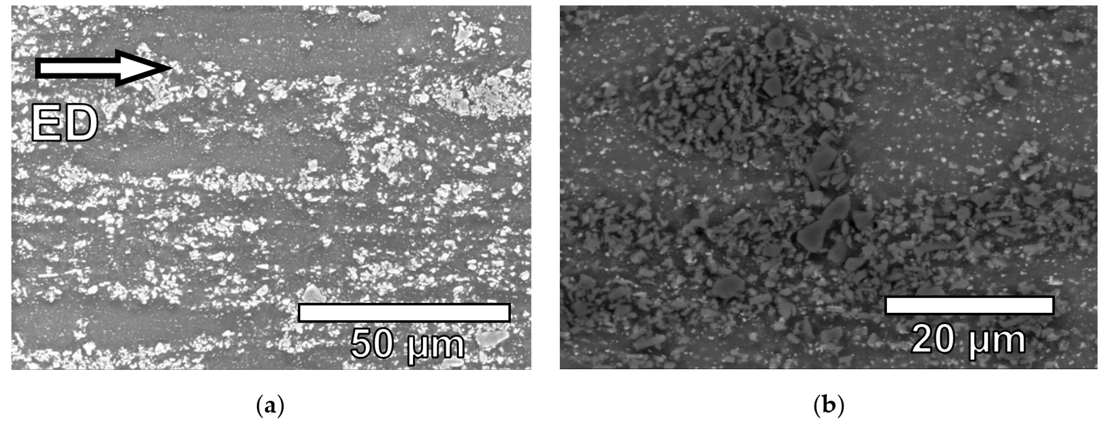
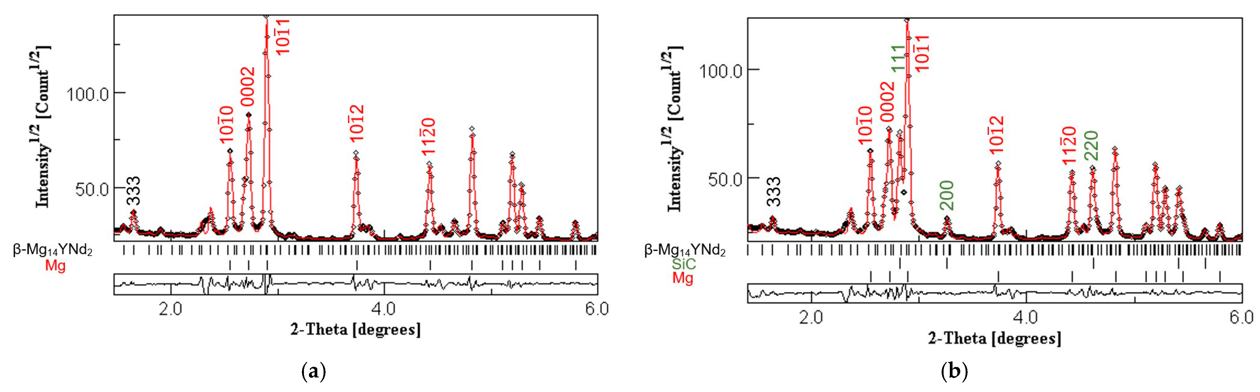
3.1. Microstructural Characterization of the WE54 Alloy and the WE54-15%SiCw Composite

Figure 2 shows backscattered electron images of the WE54 alloy along the extrusion direction. The microstructure presents intermetallic particles embedded in the WE54 matrix, with a size of around 100 nm in diameter.
Figure 3 shows bright-field images of the WE54 alloy extruded at 350 °C. Intermetallic particles are placed at grain boundaries and triple points. The grain size of the matrix is around 700 nm. The analysis of the diffraction patterns obtained from the particles in the zone axes <001>, <110>, and <111> in (Figure 3a) shows that they correspond to the cubic stable β-Mg14YNd2 phase.
Figure 4a,b shows secondary and backscattered electron images of the WE54-15%SiCw composite along the extrusion direction. In both images, the structure of the composite formed by the magnesium matrix and the ceramic particles can be clearly seen. Silicon carbide particles of about 1–2 µm appear white in the first figure and dark grey in the second. These particles are not homogeneously distributed in the matrix and show whisker agglomerations. SiC whiskers are oriented along the extrusion direction (Figure 4c,d). β-Mg14YNd2 precipitates are also observed in the magnesium matrix as in the WE54 alloy with similar particle diameter.
Figure 5a,b shows the Debye–Scherrer rings of the WE54 alloy and the WE54-15%SiCw composite material, respectively. With this technique, it is possible to determine the phases present in materials as well as their crystalline structure. A Rietveld analysis was performed on the PXRD obtained for these images. Figure 6a,b show the diagrams obtained with the Rietveld analysis for the WE54 alloy and the WE54-15%SiCw composite, respectively. For the fitting, an E-WIMV texture algorithm was used for the magnesium and SiC phases. However, in the case of the β-Mg14YNd2 precipitates, it has been assumed that they present an arbitrary or random texture. The volume fraction of the β-Mg14YNd2 precipitates is around 2.5%, and their lattices parameters are 2.24241 and 2.24250 nm for the WE54 alloy and the composite material.

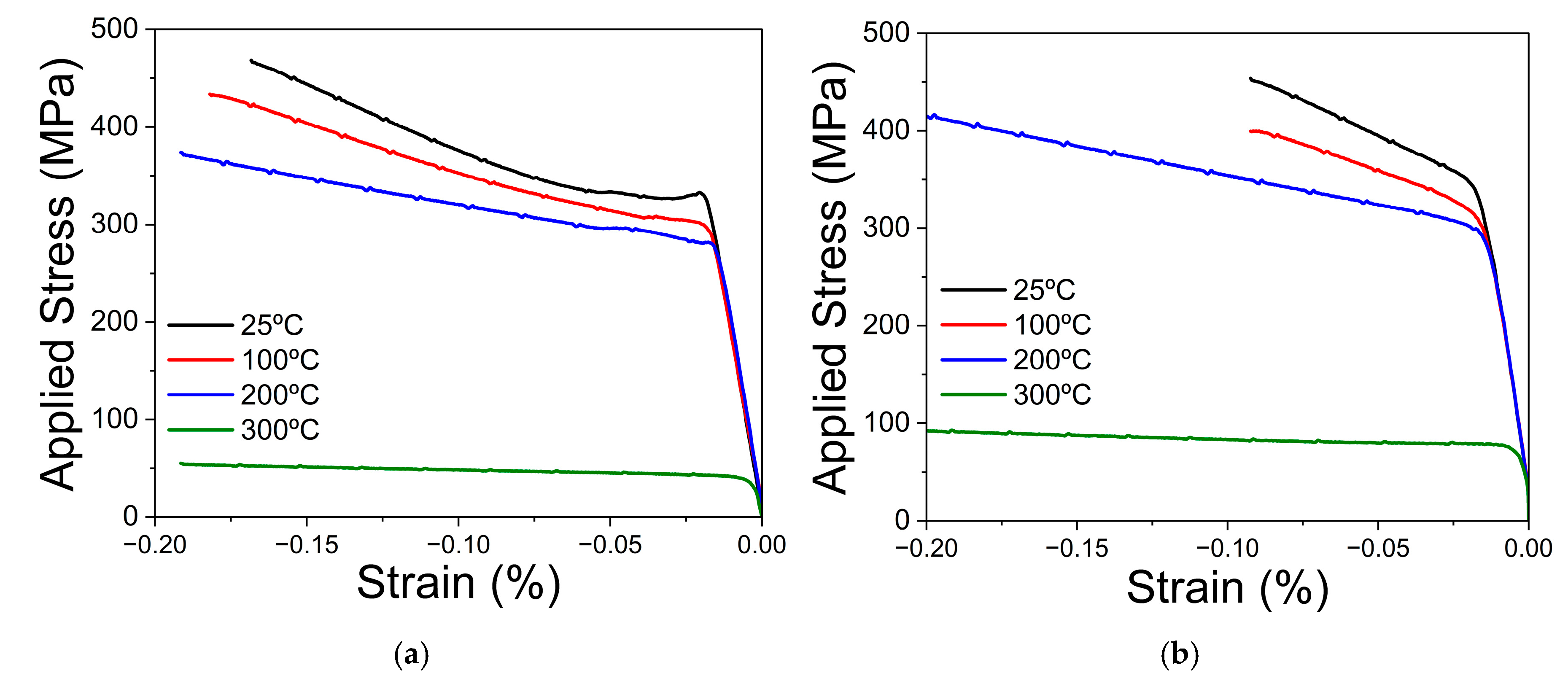
3.2. Compressive Behaviour of the WE54 Alloy and the WE54-15%SiCw Composite

Compression curves obtained during the in situ tests for the WE54 alloy and the WE54-15%SiCw composite, respectively, from room temperature to 300 °C are shown in Figure 7a,b. At room temperature, the WE54 alloy exhibits a yield point at 335 MPa. After this value, the applied stress shows a plateau, where the stress is nearly constant up to 4% plastic deformation. Beyond this deformation, the applied stress increases constantly. At 100 °C, the alloy shows a yield strength of 300 MPa. Additionally, the yield point disappears, although the plateau continues to be observed up to 2% deformation, where the applied stress increases. At 200 °C, the alloy still shows high yield strength (280 MPa). At this temperature, the yield point and the plateau disappear. Beyond the yield strength, the applied stress increases. Comparing the three temperatures, it is important to point out that hardening reduces as the temperature increases. Finally, at 300 °C, the yield strength reduces drastically (40 MPa). Beyond this value, the stress is practically constant. At this temperature, the alloy manufactured by the powder metallurgy route has shown superplastic behavior [19]. Garces et al. [24] showed similar behavior in tension, where the yield strength is maintained up to 200 °C and begins to decrease at 250 °C. In that case, yield strength values are lower because the material was extruded at 400 °C, and therefore, the grain size is slightly larger (around 2 μm).
In the WE54-15%SiCw composite material, both the yield point and the plateau after the yield strength disappear for the studied temperature range. The addition of SiC whiskers slightly increases the mechanical strength of the matrix. The evolution of the yield strength with temperature evolves in the same way as in the WE54 alloy. At room temperature, the composite material shows a yield strength of 350 MPa, while for the compression test conducted at 100 °C, the yield strength is 320 MPa. It can be seen that the compression curves of these two cases do not reach the same deformation as for the tests conducted at 200 °C and 300 °C, due to the material fracturing during the compression test. At 200 °C, a yield strength of 300 MPa is reached, but as the temperature increases to 300 °C, the yield strength is greatly reduced, and as found in the unreinforced WE54 alloy, the stress remains almost constant.

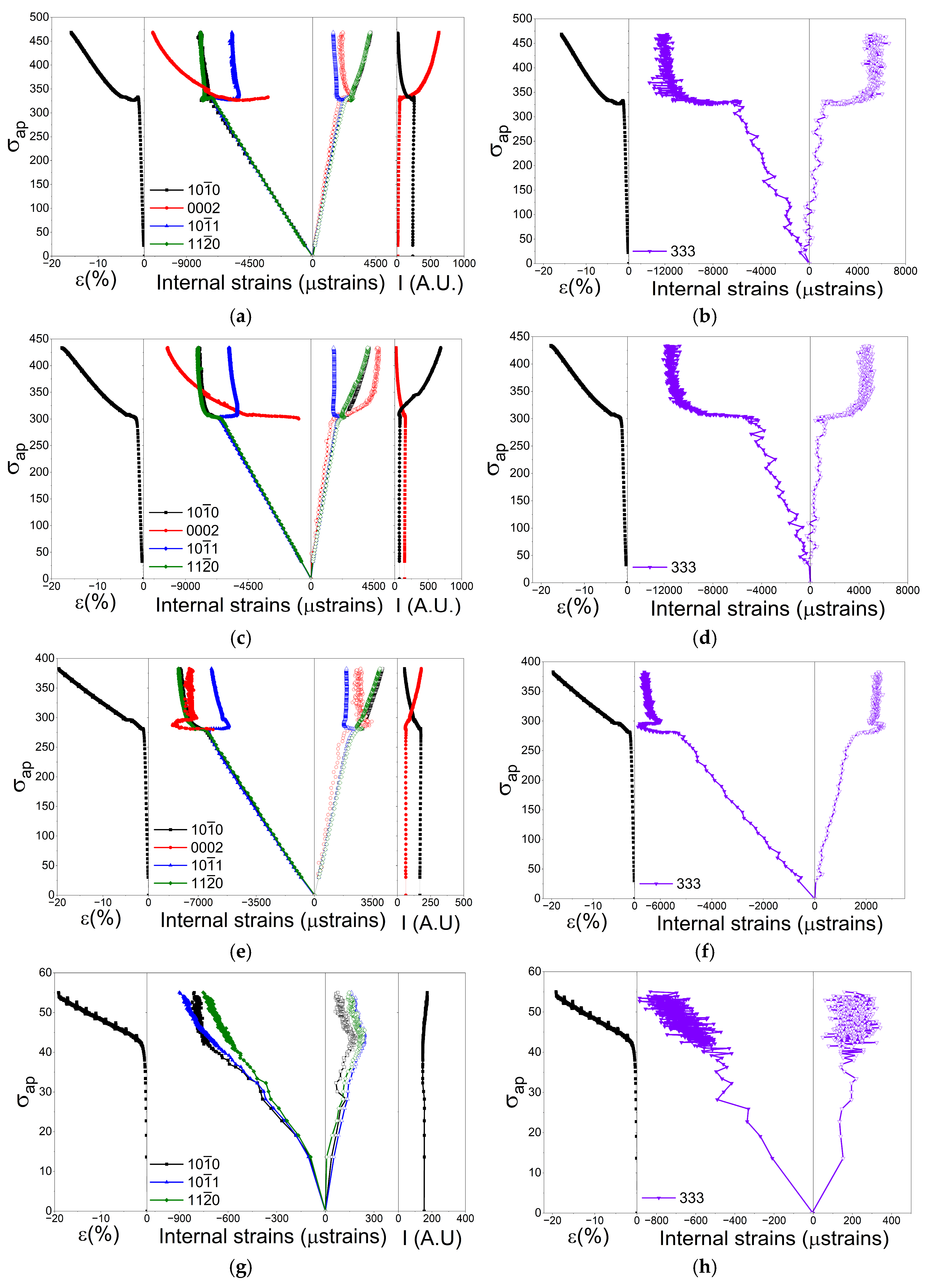
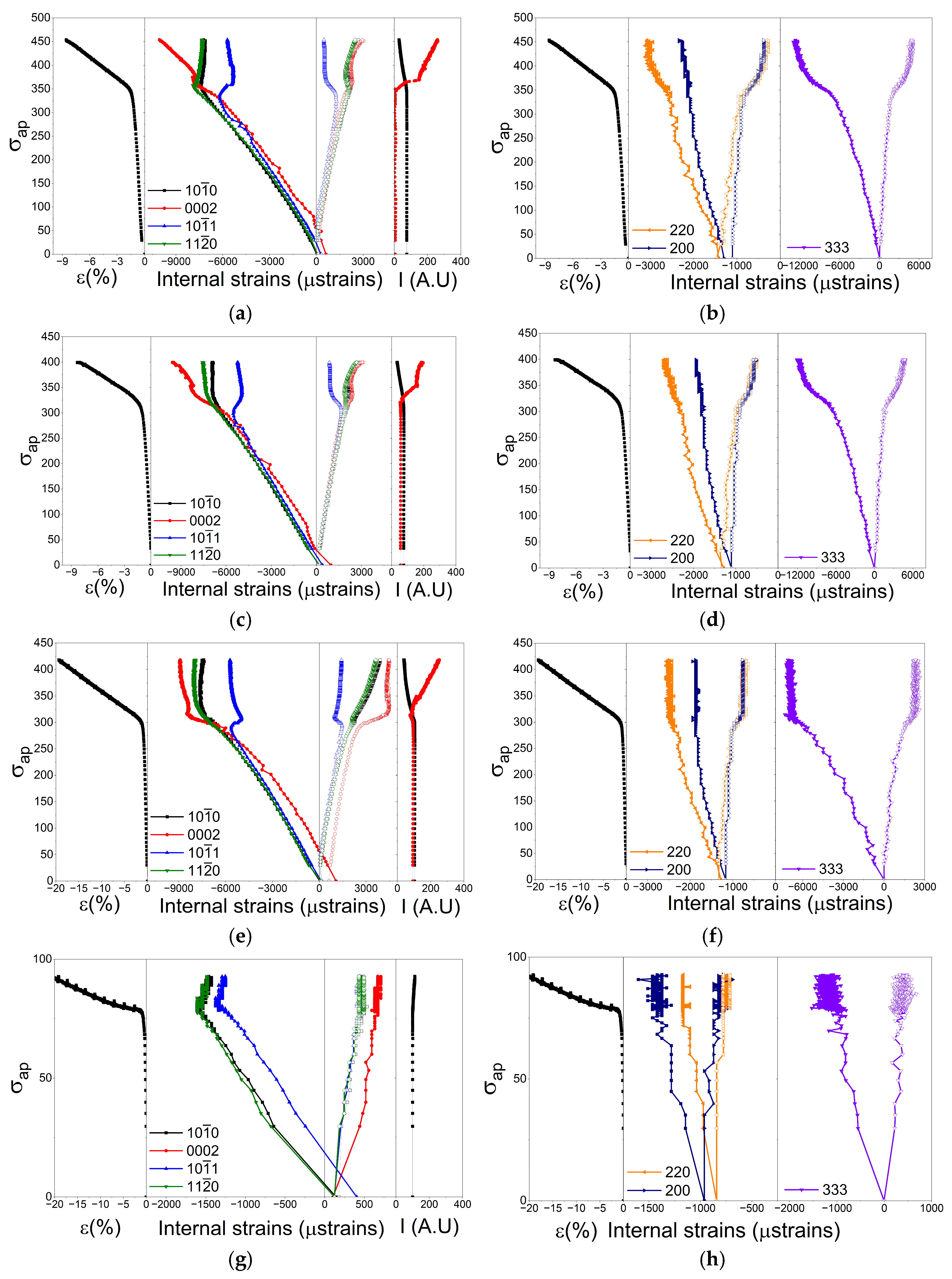
3.3. Evolution of Internal Strains in the WE54 Alloy

The elastic internal strains for each phase, matrix and β-Mg14YNd2 precipitates, have been calculated using Equation (2). Figure 8a,c,e,g show the development of the lattice strains for the extruded WE54 alloy as a function of the applied stress for the diffracted peaks {10 1 ¯ 0}, {0002}, {10 1 ¯ 1}, and {11 2 ¯ 0} of the magnesium phase in the axial and radial directions at room temperature, 100 °C, 200 °C, and 300 °C. The corresponding compression curves, are shown at the left side of this Figure to correlate the evolution of internal strains with the different regions of the curve. Furthermore, the evolution of the intensities of the {10 1 ¯ 0} and {0002} diffraction peaks, also in the axial direction, are displayed in the right side of the Figure to identify the beginning and evolution of twinning process.
Figure 8b,d,f,h present the development of the lattice strains for the diffraction peak {333} of the β-Mg14YNd2 precipitates in the axial and radial directions at room temperature, 100 °C, 200 °C, and 300 °C. Equal to the magnesium phase, the compression curves are shown at the left side of the Figures.
Initially, the results obtained at room temperature will be described in detail, and then, the most important differences will be pointed out at higher temperatures. At room temperature, the yield stress was 335 MPa. Below this stress, the linear nature of the elastic region is easily recognized in all grain families. Magnesium and its alloys exhibit isotropic elastic behaviour [42] with a slope value near 46 GPa. This value is similar to the magnesium value [43]. The {0002} peak could not be reliably fitted in the axial direction until the alloy reached the yield strength. This occurs in this material for two reasons. First, due to the fiber texture generated during the extrusion process where the grains orient their basal planes parallel to the extrusion direction, the intensity of the {0002} peak in the axial direction is small. Additionally, one of the most important peaks of the intermetallic precipitates overlaps with the {0002} peak, of the magnesium matrix.
After yielding, the different plane families exhibit three distinct behaviours. Firstly, grains oriented with the {10 1 ¯ 1} planes perpendicular to the compression axis decrease the elastic deformations by around 2000 µstrains (in absolute value) until the end of the plateau. It is important to mention that, from this moment, all µstrain variations will be expressed in absolute values for the unreinforced alloy and the composite. The increase or decrease will be referred to the negative sign of the compression test. Beyond this deformation, elastic deformations tend to remain constant. These grains are favourably oriented for the activation of the basal system. These grains are named “soft” grains [42] and transfer part of their stress to other harder orientations, resulting in a decrease in elastic deformations.
The second observed behaviour is exhibited by grains oriented with the {10 1 ¯ 0} and {11 2 ¯ 0} planes perpendicular to the compression axis. After the yield strength, opposite to the behaviour of grains oriented with the {10 1 ¯ 1} planes, the elastic deformations increase by around 1000 µstrains in both cases. After the plateau, the elastic deformations remain almost constant. These grains, opposite to “soft” grains, are not good oriented for initiating the basal system. Therefore, it is likely that dislocation slip in non-basal systems is being activated in these grains. It is well known that the inclusion of REs favours non-basal systems, mainly by increasing the CRSS of the basal system [44].
The third behaviour refers to the evolution of elastic deformations obtained from the {0002} peak, which can be satisfactorily fitted from the macroscopic yield strength of the WE54 alloy. The plastic deformation process in magnesium alloys takes place through dislocation slip and twinning. Twinning generates a rotation of 86° of the basal plane from its initial orientation. Therefore, the intensity of the (0002) diffraction peak begins to grow (see (Figure 7a)), allowing it to be correctly fitted. Thus, the (0002) diffraction peaks provide the information on the formation and evolution of twins. Elastic deformations within the twins increase rapidly and significantly, in the plateau, from −3200 μstrains to −11,400 μstrains (a difference of 8200 μstrains). Beyond the end of the plateau, the elastic deformations continue to increase in a quasi-linear manner until the fracture of the compression sample. The elastic stresses within the twins are much higher than those of the other grain families, which plastically deform by the slip of dislocations.
Precipitates also behave linearly up to the yield stress (see Figure 8b,d,f,g). Assuming an “iso-stress” approach, the Young’s modulus can be estimated at 55 GPa, which is higher than that of the magnesium phase. This behaviour is similar to that reported for other precipitates measured by diffraction; 53 GPa for the Mg17Al12 phase in Mg-Al-Zn system alloys [45], 66 MPa for the I phase in Mg-Zn-Y system alloys [46], 47 GPa for the LPSO phase [47] in Mg-Y-Zn system alloys, and 56 GPa for the β’ phase in Mg-Gd-Y-Zn system alloys [48]. After yielding, the internal deformation of the β-Mg14YNd2 phase highly increases, especially in the stress plateau, from −6000 µstrains at 325 MPa to −11,000 µstrains at 340 MPa. The internal deformation of the beta phase precipitates is much higher than that achieved with respect to any of the diffraction peaks referring to the matrix. Only the “accumulated” lattice deformation of the {0002} diffraction peak after the macroscopic yield strength approaches the value of the intermetallic phase. The behaviour of the precipitates resembles those obtained in the previously mentioned references. The precipitates, which have a higher Young’s modulus, begin to bear a load higher than the applied load, which results from load transfer from the magnesium grains, especially from grains oriented with the {10 1 ¯ 1} planes perpendicular to the compression axis. Above 350 MPa, the internal strain of the β-Mg14YNd2 phase tends to keep constant around −12,000 µstrains while the volume fraction of twins within magnesium matrix continuous to increase.
At 100 and 200 °C, where high values of yield stress are still reported, the evolution of the internal strains of grains oriented with {10 1 ¯ 0}, {10 1 ¯ 1}, and {11 2 ¯ 0} perpendicular to the compression axis is similar to those at room temperature. However, the behavior of twins oriented with the {0002} plane perpendicular to the compression axis are different depending on the temperature. At 100 °C, the behavior is identical to that at room temperature, but at 200 °C, the evolution of the internal strains of twins does not increase continuously with the applied stress. Initially, after yield stress, the internal strain increases up to 275 MPa where it reaches a maximum of −8700 µstrains. Then, elastic strain decreases up to 300 MPa, where it reaches a value of −7000 µstrains. After this stress value, the elastic strains remain almost constant.
The high increase in the elastic strains associated with twins is also manifested directly to the β-Mg14YNd2 phase. While the elastic strain at 100 °C follows the same behaviour at room temperature, the elastic strain at 200 °C shows a peak at 300 MPa, reaching a value of −6800 µstrains.
Finally, at 300 °C, the flow stress decreases dramatically, and the evolution of the internal strains of both magnesium matrix and precipitates are similar to a linear behavior up to 20% of plastic deformation. At this temperature, the diffraction peak corresponding to {0002} normal to the compression axis cannot be fitted, even after the yield stress. The intensity is negligible over the entire compression test because tensile twinning is not activated at this temperature. Therefore, only dislocation slip or grain boundary sliding could contribute to plasticity.

3.4. Evolution of Internal Strains in the WE54-15%SiCw Composite

The elastic internal strains for each phase, matrix, SiC whiskers, and β-Mg14YNd2 precipitates, have been calculated using Equation (2). Figure 9a,c,e,g show the development of the lattice strains for the extruded WE54-15%SiCw composite alloy as a function of the applied stress for the diffraction peaks {10 1 ¯ 0}, {0002}, {10 1 ¯ 1}, and {11 2 ¯ 0} of the magnesium phase in the axial and radial directions at room temperature, 100 °C, 200 °C, and 300 °C. The corresponding compression curves are shown at the left side of the Figure to correlate the evolution of internal strains though the different regions of the curve. Furthermore, the evolution of the intensities of {10 1 ¯ 0} and {0002} diffraction peaks also in the axial direction are also displayed to identify the beginning of twinning and its subsequent evolution.
Figure 9b,d,f,h present the development of the lattice strains for the diffraction peaks {200} and {220} for the SiC whikers and {333} of the β-Mg14YNd2 precipitates in the axial and radial directions at room temperature, 100 °C, 200 °C, and 300 °C. The compression curves are shown at the left side of the Figure.
Compared with the unreinforced alloy, residual stresses in the magnesium matrix and silicon carbide reinforcement are found, which are generated during the manufacturing process. Since the thermal expansion coefficient of SiC is an order of magnitude lower than that of the magnesium matrix, tensile elastic stresses are generated in the matrix and compressive stresses in the ceramic reinforcement during cooling. These residual stresses decrease at temperatures above 200 °C.
The evolution of the elastic strains obtained at room temperature will be described in detail, as in the unreinforced alloy, and then, the most significant differences will be pointed out for the materials tested at higher temperatures. At room temperature, the yield stress was 350 MPa. Below this stress, as in the WE54 alloy, the linear nature of the elastic region is easily recognized in all grain families, both in the axial and radial directions. Unlike to the unreinforced alloy, the {0002} peak could also be fitted in the axial direction. The presence of the SiC whisker randomizes the texture due to the particle stimulated nucleation recrystallization process [49]. In the axial direction, the slope value is 45 GPa, similar to the WE54 alloy.
After the yield strength, the different plane families exhibit three distinct behaviours. Firstly, grains oriented with the {10 1 ¯ 1} planes perpendicular to the compression axis decrease the elastic deformations by around 2000 µstrains. However, such decrease becomes more progressive with the increase in the applied stress up to 375 MPa than in the case of the unreinforced alloy. Beyond this stress, elastic deformations tend to remain constant. These grains are favourably oriented for the activation of the basal system.
The second observed behaviour is due to grains oriented with the {10 1 ¯ 0} and {11 2 ¯ 0} planes perpendicular to the compression axis. The elastic strains exhibit a linear behaviour until around 375 MPa, where the evolution of the elastic strains stabilizes at around −7000 µstrains. While these grains in the unreinforced WE54 alloy assumed an additional stress coming from the “soft” grains, in the composite material, these grains do not provide an additional reinforcement.
Finally, the development of the elastic strains of the {0002} grains exhibits a linear behaviour over the complete test curve. After yielding, the intensity of these peak increases due to tensile twinning activation. At 450 MPa, the elastic strain value is −9000 µstrains, which is much smaller (in absolute value) than in the unreinforced alloy. The stress borne by twins seems to be lower than the stress borne by twins in the WE54 alloy.
Intermetallic precipitates show an elastic behaviour up to the yield strength. After this stress, the internal deformation of the β-Mg14YNd2 phase steadily increases with higher rates than in the elastic regime but are more pronounced than in the unreinforced alloy.
The SiC phase shows a linear behaviour in the complete compression curve. Since the SiC phase exhibits an anisotropic elastic behaviour, the evolution of internal strains of both diffraction peaks is slightly different.
At 100 and 200 °C, where the composite presents high values of yield stress, the evolution of the internal strains of grains oriented with {10 1 ¯ 0}, {10 1 ¯ 1}, and {11 2 ¯ 0} normal to the compression axis is similar to those at room temperature. However, twins oriented with the {0002} plane perpendicular to the compression axis behave in a different way. Thus, the behavior at 100 °C is identical to that at room temperature; the evolution of the internal strains of twins at 200 °C does not increase linearly with the applied stress. After yielding, the internal strain tends to reach an asymptotic value around −9000 µstrains.
Equal to the unreinforced alloy, the increase in the elastic strains associated with twins is also manifested in both reinforcing phases, β-Mg14YNd2 precipitates and SiC whiskers. On one hand, the elastic strain of β-Mg14YNd2 precipitates and SiC whiskers evolves at 100 °C similarly to that found at 25 °C. However, the elastic strain of β-Mg14YNd2 precipitates at 200 °C presents a constant value of −6500 µstrains, while the elastic strain at 200 °C shows a constant value of −2400 and −1800 µstrains, for the {200} and {220} diffraction peaks, respectively, much lower than that found for β-Mg14YNd2 precipitates.
Finally, at 300 °C, the flow stress decreases significantly although with values slightly higher than those corresponding to the unreinforced WE54 alloy. The development of the internal strains of the reinforcing phases, the β-Mg14YNd2 precipitates and SiC whiskers, exhibits linear behaviour. Unlike unreinforced WE54 alloy, the internal strains of all diffraction peaks of the matrix are relaxed after yielding. This fact implies that part of its load is directly transferred to the reinforcing phases. Since β-Mg14YNd2 precipitates did not bear an extra load in the unreinforced WE54 alloy, it was observed that it could be expected that the higher strength of the composite should be connected to ceramic phase.

4. Discussion

The “yield point” phenomenon in the unreinforced WE54 matrix has been described in these extruded alloys processed from as-cast ingots or atomized powders [24,50]. During the extrusion process, the dislocations created are anchored by rare earth solute atoms and the precipitates. Therefore, an additional stress is required for unpinning dislocations in such a way that they can slip throughout the grain. Once this stress is exceeded, the material deforms freely under higher stresses.
In the composite material, a high dislocation density is generated at the matrix–reinforcement interface during the manufacturing process. On one hand, these dislocations are generated due to the difference in CTE between the matrix and the SiC whiskers. On the other hand, the matrix must accommodate the SiC particles during the extrusion process, creating geometrically necessary dislocations, whose source is the shearing of the particles and WE54 atomized powders. The significant increase in the dislocation density in the composite with respect to the unreinforced alloy minimizes the effect of the presence of solute atoms or precipitates, since there are always enough dislocations that can slip freely.
In situ diffraction has shown that the plastic deformation of the WE54 alloy and the WE54-15%SiCw composite is controlled by the initiation of basal and non-basal dislocations slip systems and tensile twinning. Therefore, the reinforcing phases, β-Mg14YNd2 precipitates and SiC whiskers, interact with dislocations and twins.
In the unreinforced alloy, β-Mg14YNd2 precipitates are placed at grain boundaries and within grains. Since β-Mg14YNd2 precipitates are incoherent with the magnesium matrix, dislocations bow around them during plastic deformation. On the other hand, twins engulf β-Mg14YNd2 precipitates within the magnesium grains. The presence of non-sheared precipitates will result in a plastic strain discontinuity at the β-Mg14YNd2 precipitates–matrix interface. A back-stress is generated in the matrix, which goes against the applied stress [51,52]. β-Mg14YNd2 precipitates within the magnesium grains may assume plastic strain through the formation of lattice defects due to pile ups of dislocations at their interfaces. These two facts resulted in the rapid increase in internal strains in the precipitates and the increase in the FWHM of the {333} diffraction peaks corresponding to the β-Mg14YNd2 precipitates, especially after yielding (Figure 10). At 300 °C, FWHM is constant, independently of the plastic strains, because of the insignificant interaction of dislocations with precipitates. Moreover, elongations near 300% have been reported for the unreinforced WE54 fabricated by extrusion of powders at 400 °C, which were related to the initiation of grain boundary sliding induced by the small grain size of the matrix [24].
The influence of the SiC whiskers on the mechanical strength of the composite is different than the role of the β-Mg14YNd2 precipitates. The improvement in the strength due to the inclusion of the ceramic phase has two sources. On one hand, SiC whiskers do not affect the activation of the different deformation systems. Internal elastic strains develop in a similar way to the unreinforced WE54 alloy and the composite. However, the accumulated elastic strains are reduced in the composite because a part of the applied load is borne by the SiC whiskers. On the other hand, the inclusion of the ceramic whiskers induces the development of tensile residual stress in the magnesium matrix. Therefore, a higher applied stress, in compression, is necessary to reach the same deformation by twinning compared with the unreinforced matrix. While the reinforcing effect of the β-Mg14YNd2 precipitates decreases above 100 °C, the reinforcing effect of SiC whiskers is still active at 300 °C, although its effectiveness at high temperature is low.

5. Conclusions

The development of the internal strains of each individual constituent phase of a WE54-15%SiCw composite has been evaluated using synchrotron radiation diffraction during compressive tests to understand the reinforcing effect of β-Mg14YNd2 precipitates and SiC whiskers, from room temperature to 300 °C. The following conclusions can be drawn:
(1)
The addition of SiC whiskers increases the mechanical strength across the entire temperature range studied. However, this ceramic phase is not effective in increasing the strength of the composite compared to the unreinforced. The mechanical strength decays above 200 °C, regardless of the presence of SiC whiskers.
(2)
The plastic deformation process is dominated by tensile twinning and dislocation slip both in the basal system in “soft” grains and in the non-basal system in grains oriented with prismatic planes normal to the compression axis. Twins, which are mainly oriented with the (0002) plane normal to the compression axis, significantly increase their internal elastic deformation as the applied stress raises and as the deformation proceeds in the plastic regime up to 200 °C. At 300 °C, twinning is not activated, and deformation is dominated by dislocation slip and grain boundary sliding.
(3)
β-Mg14YNd2 precipitates assume a significant load after the yield point from the magnesium matrix, which tends to relax as the temperature increases. Above 200 °C, their effectiveness disappears. Precipitates within the grains generate an opposing stress that counteracts the applied compressive stress when they are “engulfed” by the twins during their growth.
(4)
The addition of SiC whiskers generates residual stresses in the composite material, which are tensile in the magnesium matrix and compressive in the ceramic reinforcement. The reinforcing effect of ceramic whiskers is greater than that of precipitates, although it also tends to disappear at temperatures equal to or higher than 200 °C. In the initial stages of twin formation, up to 200 °C, there is a sudden change in elastic deformations. While grains oriented with {10 1 ¯ 1} planes normal to the compression axis decrease their elastic deformations (in absolute value), grains oriented with {10 1 ¯ 0} and {11 2 ¯ 0} planes normal to the compression axis increase their elastic deformations. In the composite material, this effect is minimized by the presence of the ceramic phase.

Author Contributions

Conceptualization, G.G. and P.P.; methodology, all authors; formal analysis, G.G., J.M. and P.P.; investigation, all authors; resources, G.G. and J.M.; writing, G.G. and P.P.; writing—review and editing, all authors; funding acquisition, G.G., J.M. and P.A. All authors have read and agreed to the published version of the manuscript.

Funding

We would like to acknowledge financial support of the Ministry of Science, Innovation and Universities under project number TED2021-129580B-I00.

Data Availability Statement

The original contributions presented in this study are included in the article. Further inquiries can be directed to the corresponding authors.

Acknowledgments

The Deutches Elektronen-Synchrotron DESY is acknowledged for the provision of beamtime at the P07 beamline of the PETRA III synchrotron facility. We acknowledge the service from the Microscopy Laboratory at CENIM-CSIC.

Conflicts of Interest

The authors declare no conflicts of interest.

References

  1. Luo, A. Recent magnesium alloy development for elevated temperature applications. Int. Mater. Rev. 2004, 49, 13–30. [Google Scholar] [CrossRef]
  2. Li, Y.; Zhang, A.; Li, C.; Xie, H.; Jiang, B.; Dong, Z.; Jin, P.; Pan, F. Recent advances of high strength Mg-RE alloys: Alloy development, forming and application. J. Mater. Res. Technol. 2023, 26, 2919–2940. [Google Scholar] [CrossRef]
  3. Wu, G.; Wang, C.; Sun, M.; Ding, W. Recent developments and applications on high-performance cast magnesium rare-earth alloys. J. Magnes. Alloy. 2021, 9, 1–20. [Google Scholar] [CrossRef]
  4. Moreno, I.P.; Nandy, T.K.; Jones, J.W.; Allison, J.E.; Pollock, T.M. Microstructural stability and creep of rare-earth containing magnesium alloys. Scr. Mater. 2003, 48, 1029–1034. [Google Scholar] [CrossRef]
  5. Choudhuri, D.; Srinivasan, S.G.; Gibson, M.A.; Zheng, Y.; Jaeger, D.L.; Fraser, H.L.; Hamish, L.; Banerjee, R. Exceptional increase in the creep life of magnesium rare-earth alloys due to localized bond stiffening. Nat. Commun. 2017, 8, 2000. [Google Scholar] [CrossRef]
  6. Zhu, S.; Gibson, M.; Nie, J.F.; Easton, M.A.; Dunlop, G.L. Primary creep of die-cast magnesium–rare earth based alloys. Metall. Mater. Trans. A 2009, 40, 2036–2041. [Google Scholar] [CrossRef]
  7. Polmear, I.J. Light Alloys: Metallurgy of the Light Metals, 3rd ed.; Edward Arnold: London, UK, 1995. [Google Scholar]
  8. Nie, J.F. Precipitation and Strengthening in Selected Magnesium Alloys; Magnesium Technology 2002; The Institute of Metals: London, UK, 2002; pp. 103–110. [Google Scholar]
  9. Nie, J.F.; Muddle, B.C. Characterization of strengthening precipitate phases in a Mg–Y–Nd alloy. Acta Mater. 2000, 48, 1691–1703. [Google Scholar] [CrossRef]
  10. Wang, J.G.; Hsiung, L.M.; Nieh, T.G.; Mabuchi, M. Creep of a heat treated Mg–4Y–3RE alloy. Mater. Sci. Eng. A 2001, 315, 81–88. [Google Scholar] [CrossRef]
  11. Karimzadeh, H.; Worall, J.M.; Pilkington, R.; Lorimer, G.W. Tensile and creep fracture of a Mg-Y-RE alloy. In Proceedings of the London Conference on Magnesium Technology, London, UK, 3–4 November 1986; The Institute of Metals: London, UK, 1986; pp. 47–56. [Google Scholar]
  12. Nie, J.F.; Muddle, B.C. Precipitation in magnesium alloy WE54 during isothermal ageing at 250 °C. Scr. Mater. 1999, 40, 1089–1094. [Google Scholar] [CrossRef]
  13. Antion, C.; Donnadieu, P.; Perrard, F.; Deschamps, A.; Tassin, C.; Pisch, A. Hardening precipitation in a Mg–4Y–3RE alloy. Acta Mater. 2003, 51, 5335–5348. [Google Scholar] [CrossRef]
  14. Lukyanova, E.A.; Martynenko, N.S.; Shakhova, I.; Belyakov, A.N.; Rokhlin, L.L.; Dobatkin, S.V.; Estrin, Y. Strengthening of age-hardenable WE43 magnesium alloy processed by high pressure torsion. Mater. Lett. 2016, 170, 5–9. [Google Scholar] [CrossRef]
  15. Minárik, P.; Veselý, J.; Král, R.; Bohlen, J.; Kubásek, J.; Janeček, M.; Stráská, J. Exceptional mechanical properties of ultra-fine grain Mg-4Y-3RE alloy processed by ECAP. Mater. Sci. Eng. A 2017, 708, 193–198. [Google Scholar] [CrossRef]
  16. Martynenko, N.S.; Lukyanova, E.A.; Serebryany, V.N.; Gorshenkov, M.V.; Shchetinin, I.V.; Raab, G.I.; Dobatkin, S.V.; Estrin, Y. Increasing strength and ductility of magnesium alloy WE43 by equal-channel angular pressing. Mater. Sci. Eng. A 2018, 712, 625–629. [Google Scholar] [CrossRef]
  17. Daghigh, M.; Mohri, M.; Ghanbari, H.; Nili-ahmadabadi, M. The effect of thermal and strain-induced aging on the mechanical behavior of room temperature ECAP processing of WE43 magnesium alloy. J. Mater. Res. Technol. 2023, 24, 8508–8521. [Google Scholar] [CrossRef]
  18. Sanchez, C.; Nussbaum, G.; Azavant, P.; Octor, H. Elevated temperature behaviour of rapidly solidified magnesium alloys containing rare earths. Mater. Sci. Eng. A 1996, 221, 48–57. [Google Scholar] [CrossRef]
  19. Garces, G.; Maeso, M.; Perez, P.; Adeva, P. Effect of extrusion temperature on superplasticity of PM-WE54. Mater. Sci. Eng. A 2007, 462, 127–131. [Google Scholar] [CrossRef]
  20. Knapek, M.; Minárik, P.; Greš, A.; Zemková, M.; Lukáč, F.; Bohlen, J.; Chmelík, F.; Král, R. Spark plasma sintered Mg-4Y-3Nd with exceptional tensile performance. Mater. Sci. Eng. A 2022, 849, 143481. [Google Scholar] [CrossRef]
  21. Hyer, H.; Zhou, L.; Benson, G.; McWilliams, B.; Cho, K.; Sohn, Y. Additive manufacturing of dense WE43 Mg alloy by laser powder bed fusion. Addit. Manuf. 2020, 33, 101123. [Google Scholar] [CrossRef]
  22. Smola, B.; Joska, L.; Březina, V.; Stulíková, I.; Hnilica, F. Microstructure, corrosion resistance and cytocompatibility of Mg–5Y–4Rare Earth–0.5Zr (WE54) alloy. Mater. Sci. Eng. C 2012, 32, 659–664. [Google Scholar] [CrossRef]
  23. Xu, W.; Li, J.; Zhang, Z.; Yuan, H.; An, G.; Shi, H.; Cai, C.; Jiang, W.; Li, W.; Wei, Q. Laser powder bed fusion of WE43 magnesium alloy with superior balance of strength and ductility. J. Magnes. Alloys 2024, in press. [CrossRef]
  24. Garces, G.; Rodríguez, M.; Pérez, P.; Adeva, P. Microstructural and mechanical characterisation of WE54–SiC composites. Mater. Sci. Eng. A 2010, 527, 6511–6517. [Google Scholar] [CrossRef]
  25. Száraz, Z.; Trojanová, Z.; Cabbibo, M.; Evangelista, E. Strengthening in a WE54 magnesium alloy containing SiC particles. Mater. Sci. Eng. A 2007, 462, 225–229. [Google Scholar] [CrossRef]
  26. Cabibbo, M. Compression Behavior of a Biocompatible We54 Alloy Reinforced by SiC. Biomed. J. Sci. Tech. Res. 2020, 26, 19565–19571. [Google Scholar] [CrossRef]
  27. Wang, H.; Li, J.; Wang, Y.; Guan, B.; Luo, H.; Liu, B.; Deng, D.; Chen, X.; Zheng, K.; Pan, F. Effect of multi-directional compression on microstructure and mechanical properties of Tip/WE43 composite. J. Alloys Comp. 2024, 1007, 176497. [Google Scholar] [CrossRef]
  28. Wang, H.; Li, J.; Tang, B.; Wang, Y.; Luo, H.; Guan, B.; Chen, X.; Zheng, K.; Pan, F. Heterogeneous deformation-induced strengthening of extruded Tip/WE43 composites. Mater. Charact. 2024, 207, 113526. [Google Scholar] [CrossRef]
  29. Nisar, L.; Maqbool, A.; Khan, N.Z.; Gull, A.; Siddiquee, A.N. Enhancing ductility, strength, and hardness of WE43 Mg alloy-based metal matrix composite fabricated via friction stir processing: Effect of hybrid reinforcement and Volume percentage. Mater. Chem. Phys. 2024, 323, 129620. [Google Scholar] [CrossRef]
  30. Wang, X.; Su, J.; Li, C.; Tang, J.; Jiang, F.; Fu, D.; Du, R.; Teng, J. Fabrication of high-performance biomedical rare-earth magnesium alloy-based WE43/hydroxyapatite composites through multi-pass friction stir processing. J. Mater. Res. Technol. 2024, 33, 5349–5363. [Google Scholar] [CrossRef]
  31. Maqbool, A.; Khan, N.Z. Fabrication and characterization of hybrid WE43 Mg alloy-based composite by friction stir processing with improved ductility. Vacuum 2023, 215, 112273. [Google Scholar] [CrossRef]
  32. Karthik, S.; Karunakaran, P.; Velmurugan, G. Experimental Investigation of WE43(T6) magnesium metal matrix composites to enhance mechanical properties and EDM process parameters. Int. J. Electrochem. Sci. 2024, 19, 100553G. [Google Scholar]
  33. Garces, G.; Oñorbe, E.; Pérez, P.; Klaus, M.; Genzel, C.; Adeva, P. Influence of SiC particles on compressive deformation of magnesium matrix composites. Mater. Sci. Eng. A 2012, 533, 119–123. [Google Scholar] [CrossRef]
  34. Garces, G.; Medina, J.; Perez, P.; Stark, A.; Schell, N.; Adeva, P. The effect of temperature on load partitioning evolution in magnesium metal matrix composite reinforced with Ti particles using in-situ synchrotron radiation diffraction experiments. J. Magnes. Alloy. 2023, 11, 706–719. [Google Scholar] [CrossRef]
  35. Elektron® WE54. Available online: https://www.luxfermeltechnologies.com/wp-content/uploads/2019/01/113897-Luxfer-MEL-Technologies-DS-466-Elektron-WE54-ST15.pdf (accessed on 1 January 2025).
  36. Lutterotti, L.; Bortolotti, M.; Ischia, G.; Lonardelli, I.; Wenk, H.R. Rietveld Texture Analysis from Diffraction Images. Z. Krist. Suppl. 2007, 1, 125–130. [Google Scholar] [CrossRef]
  37. Schindelin, J.; Rueden, C.T.; Hiner, M.C.; Eliceiri, K.W. The ImageJ ecosystem: An open platform for biomedical image analysis. Mol. Reprod. Dev. 2015, 82, 518–529. [Google Scholar] [CrossRef] [PubMed]
  38. Lutterotti, L.; Matthies, S.; Wenk, H.R.; Schultz, A.S.; Richardson, J.W. Combined texture and structure analysis of deformed limestone from time-of-flight neutron diffraction spectra. J. Appl. Phys. 1997, 81, 594–600. [Google Scholar] [CrossRef]
  39. Hammersley, A.P. FIT2D: A multi-purpose data reduction, analysis and visualization program. J. Appl. Crystallogr. 2016, 49, 646–652. [Google Scholar] [CrossRef]
  40. Cullity, B.D. Elements of X-Ray Diffraction Pearson Education Limited; Pearson Education Limited: Harlow, UK, 2014. [Google Scholar]
  41. Allen, A.J.; Bourke, M.A.M.; Dawes, S.; Hutchings, M.T.; Withers, P.J. The analysis of internal strains measured by neutron diffraction in Al/SiC metals matrix composites. Acta Metall. Mater. 1992, 40, 2361–2373. [Google Scholar] [CrossRef]
  42. Agnew, S.R.; Brown, D.W.; Tome, C.N. Validating a polycrystal model for the elastoplastic response of magnesium alloy AZ31 using in situ neutron diffraction. Acta Mater. 2006, 54, 4841–4852. [Google Scholar] [CrossRef]
  43. Brandes, E.A.; Brooks, G.B. Smithells Metals Reference Book; Butterworth-Heinemann: Oxford, UK, 1992. [Google Scholar]
  44. Zhang, J.; Liu, S.; Wu, R.; Hou, L.; Zhang, M. Recent developments in high-strength Mg-RE-based alloys: Focusing on Mg-Gd and Mg-Y systems. J. Magnes. Alloy. 2018, 6, 277–291. [Google Scholar] [CrossRef]
  45. Garces, G.; Medina, J.; Chávez, B.; Pérez, P.; Barea, R.; Stark, A.; Schell, N.; Adeva, P. Load partitioning between Mg17Al12 precipitates and Mg phase in the AZ91 alloy using in-situ synchrotron radiation diffraction experiments. Metall. Mater. Trans. A 2021, 52, 2732–2745. [Google Scholar] [CrossRef]
  46. Garces, G.; Medina, J.; Pérez, P.; Máthis, K.; Horváth, K.; Stark, A.; Schell, N.; Adeva, P. Influence of quasicrystal I-phase on twinning of extruded Mg-Zn-Y alloys under compression. Acta Mater. 2018, 151, 271–281. [Google Scholar] [CrossRef]
  47. Garces, G.; Medina, J.; Pérez, P.; Barea, R.; Lim, H.; Kim, S.K.; Maawad, E.; Schell, N.; Adeva, P. Study of tensile and compressive behavior of ECO-Mg97Gd2Zn1 alloys containing long-period stacking ordered phase with lamellar structure. Metals 2024, 14, 530. [Google Scholar] [CrossRef]
  48. Garces, G.; Máthis, K.; Barea, R.; Medina, J.; Pérez, P.; Stark, A.; Schell, N.; Adeva, P. Effect of precipitation on the compressive behavior of high-strength Mg-Gd-Y-Zn extruded alloy. Mater. Sci. Eng. A 2019, 768, 138452. [Google Scholar] [CrossRef]
  49. Garces, G.; Pérez, P.; Adeva, P. Effect of the extrusion texture on the mechanical behaviour of Mg–SiCp composites. Scr. Mater. 2005, 52, 615–619. [Google Scholar] [CrossRef]
  50. Zhu, S.M.; Nie, J.F. Serrated flow and tensile properties of a Mg–Y–Nd alloy. Scr. Mater. 2004, 50, 51–55. [Google Scholar] [CrossRef]
  51. Brown, L.M.; Stobbs, W.M. The work-hardening of copper-silica I. A model based on internal stresses, with no plastic relaxation. Philos. Mag. 1971, 23, 1185–1199. [Google Scholar] [CrossRef]
  52. Robson, J.D.; Stanford, N.; Barnett, M.R. Effect of precipitates shape on slip and twinning in magnesium alloys. Acta Mater. 2011, 59, 1945–1956. [Google Scholar] [CrossRef]
Figure 1. Scheme of the calculation of the internal strains, intensity, etc., during the compression test.
Jcs 09 00046 g001
Figure 2. (a) SEM micrographs of the WE54 alloy along the extrusion direction after extrusion at 350 °C. The dark and the white phase correspond to the matrix and intermetallic particles, respectively. (b) Detailed image of intermetallic particles.
Jcs 09 00046 g002
Figure 3. (a) TEM micrograph showing the grain structure and β particles at the grain boundary and SAED patterns of the β particles at the <100>, <110>, and <111> zone axis. (b) Detailed image of the β particles within the magnesium grains.
Jcs 09 00046 g003
Figure 4. Composite microstructure along the extrusion direction: (a) secondary electron image and (b) backscattered electron image. Detailed image of SiC whiskers and intermetallic particles. (c) Secondary electron image and (d) backscattered electron image.
Jcs 09 00046 g004aJcs 09 00046 g004b
Figure 5. Synchrotron radiation diffraction patterns recorded on the 2D flat-panel detector before the compressive test: (a) WE54 alloy and (b) WE54-15%SiCw.
Jcs 09 00046 g005
Figure 6. Rietveld fitting of the diffraction patterns as a function of 2θ before the compression test: (a) WE54 alloy and (b) WE54-15%SiCw.
Jcs 09 00046 g006
Figure 7. Compressive true-stress–true-strain curves of the extruded (a) WE54 alloy and (b) WE54-15%SiCw composite from room temperature to 300 °C. Negative strain values only indicate the shrinkage of the sample during the compression test.
Jcs 09 00046 g007
Figure 8. Compressive macroscopic stress–strain curve, evolution of internal strains as a function of the applied stress of {10 1 ¯ 0}, {0002}, {10 1 ¯ 1}, and {11 2 ¯ 0} diffraction peaks of the magnesium phase and evolution of the integrated intensity as a function of the applied stress of the {10 1 ¯ 0} and (0002) diffraction peaks of the magnesium phase during compression test of the WE54 alloys at (a) room temperature, (c) 100 °C, (e) 200 °C, and (g) 300 °C. Compressive macroscopic stress–strain curve and evolution of internal strains as a function of the applied stress of {333} diffraction peak of the β-Mg14YNd2 precipitates during compression test of the WE54 alloys at (b) room temperature, (d) 100 °C, (f) 200 °C, and (h) 300 °C.
Jcs 09 00046 g008
Figure 9. Compressive macroscopic stress–strain curve, evolution of internal strains as a function of the applied stress of {10 1 ¯ 0}, {0002}, {10 1 ¯ 1}, and {11 2 ¯ 0} diffraction peaks of the magnesium phase and evolution of the integrated intensity as a function of the applied stress of the {10 1 ¯ 0} and (0002) diffraction peaks during compression test of the WE54-15%SiCw composite at (a) room temperature, (c) 100 °C, (e) 200 °C, and (g) 300 °C. Compressive macroscopic stress–strain curve and evolution of internal strains as a function of the applied stress of the {200} and {220} diffraction peaks of the SiC whiskers and the {333} diffraction peak of the β-Mg14YNd2 precipitates during compression test of the WE54-15%SiCw composite at (b) room temperature, (d) 100 °C, (f) 200 °C, and (h) 300 °C.
Jcs 09 00046 g009
Figure 10. Evolution of the FWHM as a function of the applied stress of the {333} diffraction peak of the β-Mg14YNd2 precipitates during compression test of the WE54 alloy composite at (a) room temperature, (b) 100 °C, (c) 200 °C, and (d) 300 °C. The compressive curves are also included for comparison purpose.
Jcs 09 00046 g010aJcs 09 00046 g010b
Table 1. Chemical composition of Elektron WE54 alloy [35].
YttriumNeodymiumHeavy Rare Earths 1ZirconiumMagnesium
4.75–5.5%1.5–2.0%1.0–2.0%0.4% min.Balance
1 Heavy rare earth fraction contains mainly Yb, Er, Dy, and Gd.
Table 2. Setup parameters of the measurements.
Setup Parameters
Gauge volume0.8 × 0.8 × 5 mm3
Exposure time0.5 s
Effective pixel size200 × 200 µm2
Energy/Wavelength100 keV/0.01202 nm
Detector-to-sample distance1640 mm
Integration angle±7.5°
Disclaimer/Publisher’s Note: The statements, opinions and data contained in all publications are solely those of the individual author(s) and contributor(s) and not of MDPI and/or the editor(s). MDPI and/or the editor(s) disclaim responsibility for any injury to people or property resulting from any ideas, methods, instructions or products referred to in the content.

