Article

Advanced Numerical Free Vibration Analysis of FG Thin-Walled I-Beams Using Refined Beam Models

1
Civil Engineering Department, University of Science and Technology Houari Boumediene (USTHB), Algiers 16111, Algeria
2
Civil Engineering and Hydraulic Laboratory, University of 8 May 1945 Guelma, P.B. 401, Guelma 24000, Algeria
3
LEME, Université Paris Nanterre, 92410 Ville d’Avray, France
4
Civil Engineering Department, Mentouri University of Constantine, Constantine 25017, Algeria
*
Authors to whom correspondence should be addressed.
J. Compos. Sci. 2025, 9(1), 19; https://doi.org/10.3390/jcs9010019
Submission received: 17 October 2024 / Revised: 29 November 2024 / Accepted: 18 December 2024 / Published: 3 January 2025
(This article belongs to the Section Composites Modelling and Characterization)

Abstract

:
This paper presents a numerical analysis of the free vibration of thin-walled composite and functionally graded material (FGM) I-beams, considering the effects of bending–torsional behavior using refined beam theory models RBT and RBT* built on the 3D Saint-Venant (SV) solution. The models enable a realistic analysis of beams with arbitrary cross-sections, overcoming the limitations inherent in classical beam theories. They incorporate a set of 3D displacement modes, representing cross-sectional deformations, which are derived from 2D FEM calculations. These modes are then applied to solve the beam problem using a 1D FEM, providing the 3D vibration modes and natural frequencies. The mechanical properties of the FGM thin-walled beams are varied according to different material distributions across the cross-section. A numerical comparison of the natural frequencies and 3D mode shapes of the thin-walled beams is carried out to validate the proposed models against available results from the literature and 3D FEM calculations. The results confirm that the RBT models provide accurate and efficient analysis of thin-walled I-beams subjected to various boundary conditions.

1. Introduction

Functionally graded materials (FGMs) are a class of advanced engineering materials that have been widely studied and utilized in various applications in recent decades. FGMs are characterized by their spatially varying material properties, which are tailored to achieve specific performance requirements. FGMs emerged among a group of researchers at the National Space Laboratory in Japan [1,2,3]. The mechanical properties of FGMs vary according to a continuous gradient of two or more components (often between ceramic and metal) in one direction (thickness or length) or two directions (length and thickness). As a new composite material, FGMs have an enormous ability to reduce stress concentration and mitigate thermal stresses, and these unique characteristics make them a preferred material for use in various new structures [4]. FGMs are used in many fields, for example in the automotive and aerospace industries, in civil and mechanical engineering, and in various machine components [5].
In the last two decades, there has been a considerable increase in the number of research publications. The computational modeling of FGMs is a significant tool for the understanding of static, vibration, and buckling analyses and has been the subject of much research [6,7,8,9,10,11,12,13,14,15,16,17,18,19,20].
The free vibration of functionally graded material (FGM) beams under concentrated moving harmonic load using the Euler–Bernoulli beam theory was studied by Simsek and Kocaturk [21]. It was demonstrated that the exponential law and the power law form play a crucial part in the analysis of free vibration. Latifa Ould Larbi et al. [22] proposed an advanced shear deformation beam theory that accounts for the neutral surface position, enabling precise analysis of bending behavior and free vibration characteristics in functionally graded beams. Shahba et al. [23] studied the analysis of the free vibration and stability of an axial FG beam using the Timoshenko beam theory (TBT). It was found that the natural frequencies varied as a function of the boundary conditions, and that the critical load increased as a function of the non-homogeneity parameter of the material. Sankar [24] found the solution for a rectangular FG beam subjected to sinusoidal transverse loading using the Euler–Bernoulli beam theory. It was discovered that if the load was a slowly changing function of the axial coordinate, the precise elasticity solution for stresses and displacements was true for long, thin beams. In addition, it was shown that engineering theory cannot account for geometric effects on stress concentration in thin or thick beams. Thai et al. [25] developed a number of higher order shear deformation beam theories for the bending and free vibration of FG beams. The study showed that increasing the power index reduces the FG beam stiffness and, as a result, leads to increased deflections and decreased natural frequencies. Hadji et al. [26] developed a new model of high-order shear deformation in order to study the problem of static and free vibration of FG beams. Şimşek [27], based on the different first order and higher order shear deformation beam theories, presented the fundamental frequency analysis of FG beams under various boundary conditions. Higher order shear deformation theories can be constructed on the basis of a higher order variation of the axial displacement across the depth of the beam [28,29,30,31]. Note also the substantial work on the structure of beams based on the Carrera unified formulation (CUF). Hierarchical models are built from classical to higher order beam theories [32,33].
Most of the above mentioned papers deal with free vibrations of rectangular FG beams. In addition, all the higher order beam theories and the finite element method have shown their potential to easily and accurately solve many structural problems that cannot be analytically solved. Moreover, the mechanical behavior of open cross-section (thin-walled) beams made of anisotropic materials is characterized by a coupled and very complex structure. The third-order shear deformation theory based on elasticity theory is employed to analyse the vibration and linear thermal buckling of FG beams [34]. Many papers have included thin-walled laminated composite beam theories that address various problems related to beams [35,36,37]. Lee [38] created the model to accurately estimate natural frequencies and shapes of vibration modes for different configurations such as laminate orientation, boundary conditions, elastic modulus ratio, and composite beam height to thickness ratio.
RBT/SV can be considered as a very extensive generalization of Vlasov’s theory; the latter is only concerned with torsional warping for the special case of homogeneous and isotropic open thin sections, whereas RBT addresses any cross-section (shape and material) and takes into account all types of cross-sectional deformations. A lot of the literature investigated the problem of static, vibration, buckling, and thermoelastic equilibrium of many beams with a homogeneous or composite cross-section using RBT [39,40,41,42]. These studies included a set of 3D displacement modes (in- and out-of-plane warping) of the cross-section reflecting its 3D mechanical behavior.
For open section and thin-walled beams with FGM, extensive modeling and analysis has been carried out to predict the free vibration and the mechanical behavior of the beam. Linh et al. [43] developed the finite element model to study the problem of free vibrations for thin-walled beams with FGM. The study focused on two variations of FG thin-walled beams (mono-symmetric I-section and channel section). In these structures, the mechanical and physical properties of the FGM beam vary continuously, depending on a power law distribution across the contour direction of the thin-walled beam. Nguyen et al. [44,45] investigated the statics, vibrations, and buckling of an FG beam across the thin-walled thickness for three different types of thin-walled FG beams.
The objective of this present paper is to examine the ability of refined 1D beam theory models based on the 3D SV (RBT/SV) solution to study the free vibrations of FGM beams. The models examined are implemented on the CSB (Cross-Section and Beam Analysis) tool [39]. The FGM beam I-section is chosen in this study, under different boundary conditions. The material variance associated with Young’s modulus is assumed to be graded through the contour direction, while Poisson’s ratio is considered constant. In addition, the combined effect of axial displacement and curvature is examined. These kinematic models (RBT/SV) include Poisson’s effect, and in-plane and out-of-plane deformation of the cross-sections, which are derived from a 3D Saint-Venant (SV) solution. In addition, the influence of the power index on the natural frequencies and shapes of symmetrical cross-sections is also investigated. The results of using RBT models for a laminated composite beam (I-section) are compared with the literature, while the results for thin-walled beams with FGM are compared with those provided by the full 3D FEM calculations by using the Abaqus finite element code.

2. The Refined Beam Theory RBT

2.1. The Original Model

RBT is a higher order beam theory (HOBT) based on a displacement model of the 3D SV solution.
In order to clearly describe this theory (more details in [20]), let us begin with the general HOBT displacement model:
U R B T x , y , z = ξ u , ω , η = u ( z ) + ω ( z ) X r i g i d   m o t i o n   o f   t h e   s e c t i o n + k = 1 p   η k ( z ) M k ( x , y ) e n r i c h m e n t
where u and ω are the translation and rotation, respectively, and η k is a set of p extra kinematic parameters ( K P ) associated with the sectional displacement modes M k that are assumed to be known. X is the location of the in-section vector. The beam axis is z , and the cross-section axes are x , y .
The total number of K P in this model is ( 6 + p ) : the three translations u x , u y , u z , the three rotations ω x , ω y , ω z , and the p η k related to the sectional modes M k .
The enrichment part is included to allow for some section deformations, where M k is based on modeling that accounts for the nature of the cross-section in terms of shape and materials.
Once the set M k is sufficiently representative of the mechanics of the cross-sections, this provides a beam theory (RBT/SV) that actually corresponds to the nature of the cross-sections, and therefore the beam problem.
Besides, all the CS models M k are extracted first from the CS analysis related to the 3D SV solution.
The 3D SV solution (also known as the central solution) is essential because it describes the precise 3D solution in the inner area of the beam. Therefore, it represents the actual mechanical behavior of the cross-section due to its shape and materials. In addition, the 3D SV solution is a linear function of the six cross-sectional stresses N , M x , M y , T x , T y , M t and is polynomial with respect to the beam axis. Using these properties, the 3D SV solution can be divided into a set of problems consisting of a set of 1D equations defining a beam theory and a set of 2D equations defining the cross-sectional behavior.
All sectional modes M k in R B T / S V come from the cross-section analysis connected to the computation of the 3 D SV solution. The sectional modes covered in the R B T / S V displacement model are as follows:
M k = Π s v i , ( i = 1 , , 6 ) ; Ψ s v i , ( i = 1 , , 6 ) ; Φ s v j , ( j = 1 , , m )
where
Ψ s v i = M s v i z z , ( i = 1 , , 6 ) are the six CS (SV) out-of-plane warpings associated with the six CS stresses N , M x , M y , T x , T y , M t ;
Π s v i = M s v i Ψ s v i , ( i = 1 , , 6 ) are the six CS (SV) Poisson’s effects associated with the six CS stresses N , M x , M y , T x , T y , M t ; and
Φ s v i , ( i = 1 , , m ) are m additional CS (SV) distortional modes associated with localized lateral loads. These additional modes are typically utilized when a thin- and thick-walled section is involved.
In the case of a thin-/thick-walled section, this model (RBT) yields   ( 6 + 12 )   K P and ( 6 + 12 + m )   K P .

2.2. A Refined Beam Theory Using the Distortional Modes RBT*

In this paper, an improved displacement model is also considered, which is also built on SV’s solution [20,46,47]. The new displacement model RBT* is written as follows:
U R B T * x , y , z = u ( z ) + ω ( z ) X + i = 1 6   α i ( z ) M s v i ( x , y ) s h a p e   o f   S V   d i s p l a c e m e n t + j = 1 m   β j ( z ) D v j ( x , y )
where the displacement model here includes the following cross-section modes:
  • M s v i are the six SV’s 3D modes associated with the 6 cross-section stresses T x , T y , N , M x , M y , M t without splitting them into in-plane modes ( Ψ s v i ) and out-of-plane modes ( Π s v i ) , respectively.
  • D v j are additional modes that used in a thin- or thick-walled segment or in highly differentiated composite sections, where these modes represent the first m 3D mode shapes associated with the free vibration of the cross-section, which mainly reflect the sectional distortions.
In this model, each 3 D mode M s v i is utilized without separating in-plane and out-of-plane components, resulting in ( 6 + 6 )   K P . Besides, the method for obtaining cross-section modes { D v j } is methodical and easier than the procedure used to obtain SV’s distortional modes Φ s v i , (see [39] for details).
This model yields ( 6 + 6 )   K P and ( 6 + 6 + m )   K P , if the additional sectional distortional modes m are added

2.3. Cross-Section Analysis Problem

The initial cross-section analysis, which can be solved using 2D FEM, yields all of these modes M s v i , D V j .

2.3.1. Analysis of the Saint-Venant Cross-Section

The Saint-Venant (SV) sectional modes M s v i ; i = 1 , , 6 are calculated using the 3D SV solution. This is accomplished using the numerical approach described by El Fatmi and Zenzri [48]. This technique involves utilizing the CSection tool (see Section 3) to solve a collection of 2D elastic linear problems defined on the cross-section. More information is available in [48,49].

2.3.2. Dynamic Analysis of the Cross-Section

The first m mode shapes connected to the free vibration of the cross-section are the distortional modes D V j . The following variable equations govern the free vibration of the cross-section S, deducing the cross-section eigenmode shapes and frequencies:
div   σ = k 2 ρ W o n   S σ = K : ε o n   S ε = 1 2 t W + W o n   S σ n = 0 o n   S
W ( x , y ) represents the three-dimensional displacement field vector, and k the eigenfrequency ( k has a positive value to remove the rigid motion of the cross-section). The elastic tensor field is denoted by K , and S is the boundary of the cross-section S.
The equivalent 2D weak formulation of Equation (4) is given as follows:
F i n d { W , κ }   s u c h   a s S   ε ( W ^ ) : K : ε ( W ) d S κ 2 S   W ^ t W ρ d S = 0   W ^
This cross-section problem expressed as a linear eigenvalue problem is solved by 2D FEM.
Thus, the set of the m first eigenfrequencies { κ j } and { D V j }, the related set of mode shapes, can be deduced. They are chosen to be included in the enrichment part of the displacement model (Equation (3)).

2.4. Free Vibration of a Composite Beam

Based on the cantilever beam shown in Figure 1, the main methodology and equations are derived to analyze the free vibration problem.
The console beam has a constant (unspecified) cross-section S and length L, while the composite beam is oriented along the z-axis and occupies a prismatic domain Ω with a constant z. S 0 and S L are the end sections, and S lat   is the lateral surface. The elastic tensor field denoted by K is the z -constant. The materials that make up the cross-section are perfectly interconnected with each other, and have linear elasticity and are anisotropic.
Assuming ( ξ ( x , y , z , t ) = ξ ( x , y , z ) s i n ( λ t ) ) harmonic motion, the 3 D prismatic body’s free vibration characterizes its own spectrum of frequencies and their respective 3 D mode shapes λ i , ξ i . These are the solutions to the following equations:
div σ = λ 2 ρ ξ o n   Ω σ = K : ε o n   Ω ε ( ξ ) = 1 2 t ξ + ξ o n   Ω σ n = 0 o n   S lat   σ z = 0 o n   S L ξ = 0 o n   S 0
where σ is the stress tensor, ρ the material mass density, and ε ( ξ ) the strain tensor related to the field of displacement. ξ ( ) t   and   ( : ) indicate transposition and double contraction operators, and n is the normal and exterior unit vector of S lat   .
The three-dimensional formulation for this problem can be written as follows:
P 3 D : f i n d { λ , ξ } s u c h   a s Ω   ε ^ : K : ε d Ω λ 2 Ω   ξ ^ ξ ρ d Ω = 0 ξ ^ ξ = 0   o n   S 0
From this formulation, a 1D weak formulation will be deduced. ξ ^ is any virtual displacement field defined on Ω , such as ξ ^ = 0 on S 0 .
In order to determine the 1 D weak formulation and displacement model, the numerical solutions to this 3D problem will be implemented by 1 D FEM, by using the 1 D beam displacement model.

The 1D Problem

The displacement model given by Equation (3) produces the RBT, and its equations can be derived through the principles of variation. Equation (7) will be used to derive the relevant 1D formulation for the 3D beam free vibration. The displacement model is represented in compact form using matrix notation as follows:
ξ x , y , z = u z + ω z X + i = 1 6   α i z M s v k x , y + j = 1 m   β j z D V j x , y = u x 1 0 0 + u y 0 1 0 + u z 0 0 1 + ω x 0 0 y + ω y 0 0 x + ω z y x 0 + i = 1 6   α i M x i M y i M z i + j = 1 m   β j D x j D y j D z j
where M s v k = M x k , M y k , M z k t   and D V j = D x j , D y j , D z j t using matrix notation. In Equation (8), the field of displacement is written again as follows:
ξ ( x , y , z ) = [ A ] ( x , y ) × U ( z )
where
[ A ] = A x A y A z = 1 0 0 0 0 y M x 1 M x 6 D x 1 D x m 0 1 0 0 0 x M y 1 M y 6 D y 1 D y m 0 0 1 y x 0 M z 1 M z 6 D z 1 D z m
and
U = u x , u y , u z , ω x , ω y , ω z , α 1 , , α 6 , β 1 , β m t
The corresponding strain tensor ε = ε x x , ε y y , 2 ε x y , 2 ε x z , 2 ε y z , ε z t is expressed in the same way:
ε ( x , y , z ) = [ B ] ( x , y ) D ( z )
where
[ B ] ( x , y ) = A x , x [ 0 ] A y y [ 0 ] A x , y + A y , x [ 0 ] A x , z A x A y , z A y [ 0 ] A z D ( z ) = U U ( z )
and ( ) , x ,   ( ) y ,   and   ( ) indicate the partial derivatives with respect to x ,   y , and z , and [ 0 ] is a null vector. D and U represent the strain vectors and generalized 1D displacement, respectively.
Suppose U ^ be a virtual generalized displacement fulfilling U ^ = 0 at z = 0, where S 0 represents the boundary conditions. Using Equations (9)–(12), we can demonstrate that the weak formulation of Equation (7) for the 3D beam issue P 3 D can be reduced to the following 1D weak formulation after integration on S.
P 1 D : f i n d   { λ , U }   s u c h   a s L   D t [ Γ ] D d z λ 2 L   U t [ M ] U d z = 0 ( U ^ ) U = 0   a t   z = 0
where M and Γ , the mass and stiffness matrices, are provided as follows:
[ M ] = S   [ A ] t ρ [ A ] d S
[ Γ ] = S   [ B ] t [ K ] [ B ] d S
where M and Γ are the mass matrices and stiffness of the 1 D beam structural behavior, respectively.
K is the matrix (6 × 6) associated with the elasticity tensor K .
This problem is solved by introducing 1D FEM. In Equation (14), as a linear eigenvalue problem, the correspondent three-dimensional mode shape is deduced from ξ s ( x , y , z ) = A ( x , y ) U s ( z ) for each one-dimensional solution mode shape U s ( z ) .
The 1D structural behavior is also denoted as follows to obtain the governing local equations:
Γ × D = Γ 11 Γ 12 Γ 21 Γ 22 × U U
Based on Equation (14) and employing Equation (17), we can show that the following differential equation system’s U s is the solution by means of the Lagrange equations:
Γ 22 U + Γ 21 Γ 12 U Γ 11 U = λ 2 [ M ] U U ( 0 ) = 0
M expresses the inertial couplings, and Γ 11 , Γ 12 , Γ 21 ,   and   Γ 22 the structural operators’ off-diagonal elements, which express the elastic couplings. In the RBT model, both couplings are naturally taken into account.

3. Constitutive Equations for an FGM Beam

A basic rule of combination of constituent material properties P i is used, as in [5,50,51].
P = P m V m + P c V c
where P m , P c represent the characteristics of metal and ceramic, respectively. The expression is used for Young’s modulus, Poisson’s ratio, shear modulus, and density.
The distribution of volume fraction for metal V m and ceramic   V c can be written as follows:
V m = 1 V c
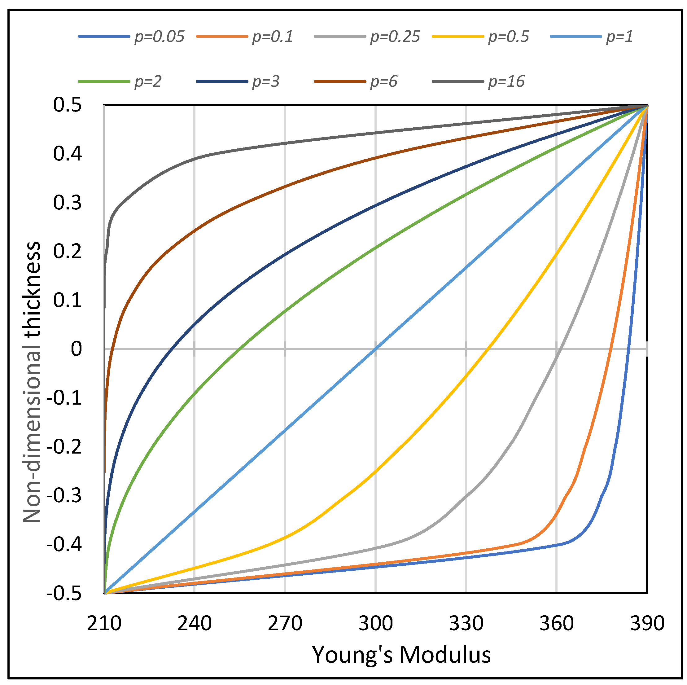
Figure 2 illustrates the variation of Young’s modulus for the rule of mixtures [5] with consideration of various power law indexes p from ceramic ( E c = 390   G P a ) to metal ( E m = 210   G P a ) along the contour direction.
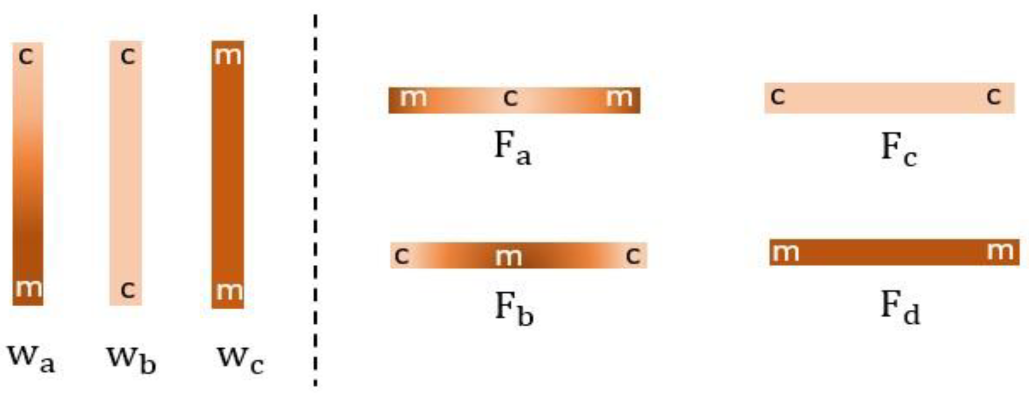
We use five types of material distributions for both the flanges and the web. More details about these types are presented in Section 5.4.
Type F a
V c = 2 s b + 1 p , b 2 s 0
V c = 2 s b + 1 p , 0 s b 2
Type F b
V c = 2 s b p , b 2 s 0
V c = 2 s b p , 0 s b 2
Type W a
V c = s b + 1 2 p , b 2 s b 2

4. Numerical Implementation (RBT/SV and 3D FEM Computations)

In this work, the RBT/SV model was introduced using a tool called CSB [39].
CSB is a numerical tool dedicated to the calculation of beams with any cross-sectional shape, made of freely arranged isotropic or anisotropic materials. It is used to solve within the standard framework of linear elasticity the equilibrium of a beam subjected to any loading and support conditions. In addition, CSB enables users to perform numerous simulations quickly and easily, providing a relatively realistic 3D visualization of beams that contrasts with traditional approaches. This allows users to explore its inherent effects in comparison to other existing tools. CSB is proposed as a set of two complementary numerical tools CSection and CBeam.
CSection determines the mechanical properties of the cross-section using 2D finite elements. This part is devoted to the derivation of the cross-sectional modes M s v i ( i = 1 , , 6 ), and the modes D V j according to the dynamic problem of the cross-section defined by Equation (5). In CSection, the 2D FEM computations are carried out exclusively using 6-node triangular finite elements.
CBeam uses these cross-section modes to calculate the beam using 1D finite elements, to produce systematically the correspondent beam theory, and to solve by 1D FEM the eigenvalue dynamic of the beam problem defined by Equation (14). The linear buckling beam problem and the static thermomechanical beam problem have already been presented in [52] and [39,40], respectively.
For the 3D FEM calculations, the commercial code Abaqus is used. The calculations are performed using the 15-node quadratic triangular prism (C3D15).

5. Numerical Results

5.1. Cross-Section Analysis

Using the CSection tool, 2D FEM analyses of the various beams studied in this paper were performed. This tool provides, for each section, the six cross-section modes ( M s v i ) in addition to a set of m distortion modes ( D V j ) related to the free vibration of the section.
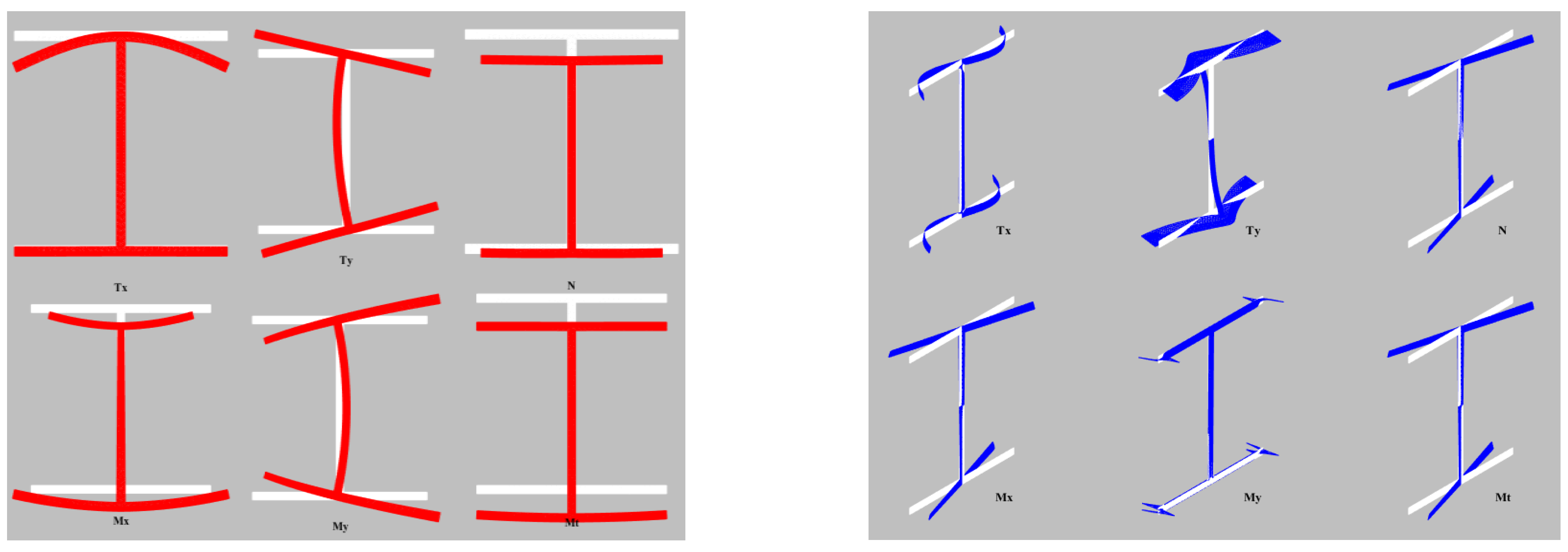
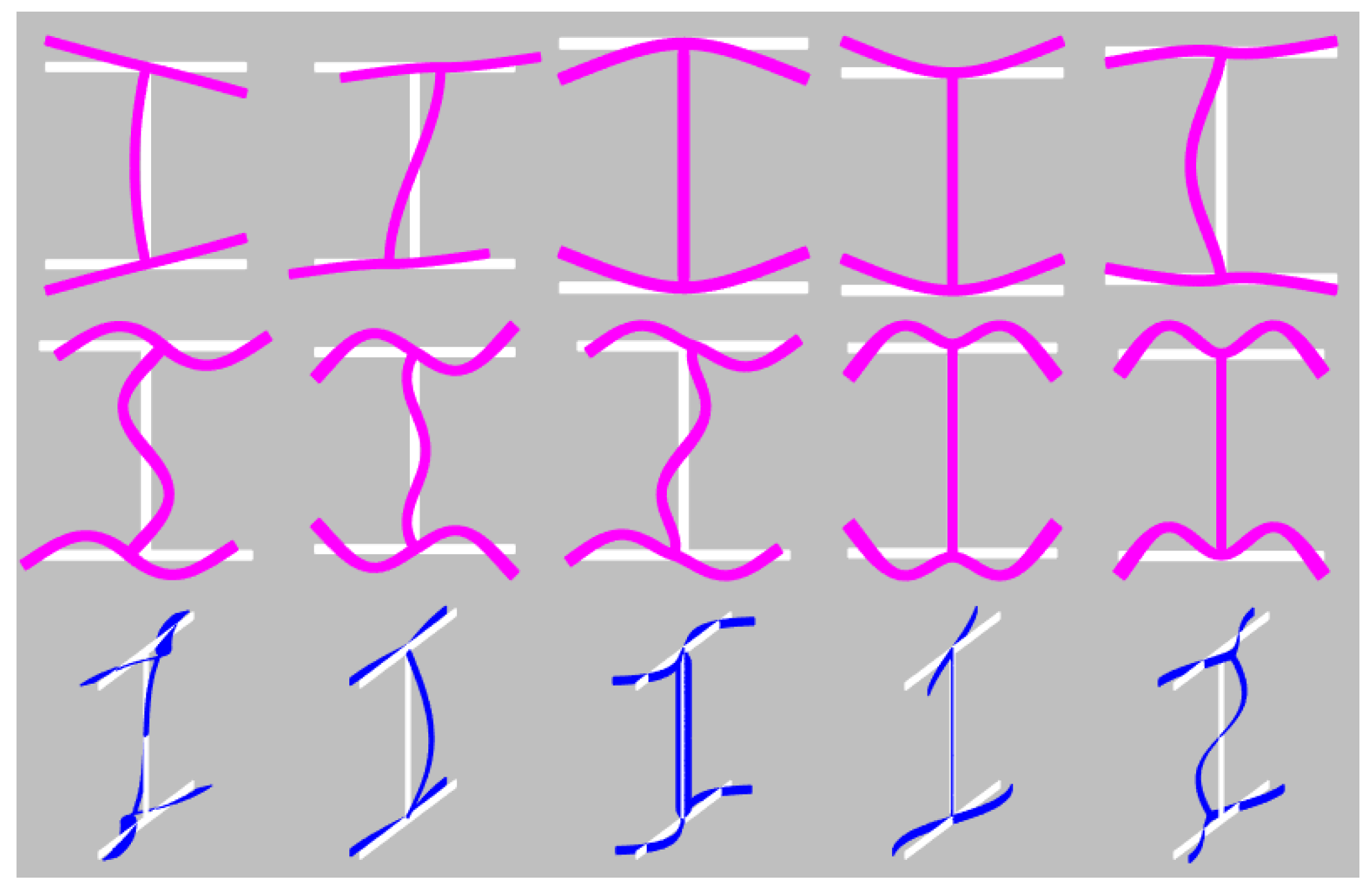
Figure 3, Figure 4 and Figure 5 present the six transverse modes [ T x , T y , N, M x , M y , M t ] associated with the classical transverse stresses of each example studied in this paper (Section 5.2, Section 5.3 and Section 5.4): a laminated composite beam, a cantilever beam, and an FGM beam, respectively. The deformation modes in red color indicate Poisson’s effect, while the deformations in blue color indicate the out-of-plane warpings. All these deformations are related to the axial force ( N ), the bending moments ( M x , M y ), the shear forces ( T x , T y ), and the torsional moment ( M t ). In addition, some additional sectional distortions are taken into account for the I-section of the different beams of each example: 10 in-plane (pink colour) and 5 out-of-plane (blue colour), as shown in Figure 6, Figure 7 and Figure 8.

5.2. Example 1

This example demonstrates the validity and accuracy of refined beam theory (RBT) models for the free vibration behavior of a thin-walled laminated composite beam. The symmetrical angle-ply I-beam with different boundary conditions (BCs) is considered. The material properties for this laminated composite beam are as follows: E 1 = 53.78   G P a ,   E 2 =   E 3 = 17.93 G P a , G 12 = G 13 = 8.96   G P a , G 23 = 3.45 G P a , v 12 = v 13 = 0.25 , and ρ = 1968.90 k g / m 3 . The flanges and web have a thickness of 0.208   c m and are composed of symmetric laminates with 16 layers [ η / η ] 4 S (see Figure 9). Each layer has the same thickness of 0.013   c m . We also have b 1 = b 2 = b 3 = 5   c m   and L = 200   c m . The first natural frequencies of an S–S and C–C I-beam are displayed in Table 1 and Figure 10. A comparison of the results obtained from the proposed RBT models, Sheikh et al. [53], the analytical model based on shear-deformable theory by Vo and Lee [54], the Ritz method (non-shear deformable and shear deformable theory) by Ngoc et al. [55], and the analytical approach by Kim et al. [56] for different stacking sequences indicate good agreement.

5.3. Example 2

This numerical example focuses on a cantilever beam with an I-shaped cross-section. The beam is 1 m long. The geometry of the cross-section is shown in Figure 11. The material properties of this composite beam are given in Table 2. The natural frequency values with laminations (0) and (60) are summarized in Table 3 using the present models of RBT and different beam models. The natural frequency values obtained by the RBT models show good agreement with the CUF 1D model and Abaqus shell [57]. Due to the deformation modes introduced by the RBT models, the natural frequencies derived from these models are higher than those of other structural models. Particularly for this example, mode 6 was included in the investigation because it is a fifth-position distortion mode with lamination (60). For the classical mode shapes (bending, torsional, and extension modes), the RBT predicts very accurate frequencies, and the frequencies improve somewhat when the D V j cross-section distortion modes are included in the displacement field for RBT* (see Equation (3)). This improvement is most noticeable at higher frequencies. For completeness, the first ten mode shapes obtained by the RBT model for this composite beam with lamination (30) are presented in Figure 12. These modes shapes can be compared with the mode shapes obtained using the CUF 1D model [57].

5.4. Example 3

In this section, a thin-walled I-shaped FGM beam is considered for investigation of the power law effects on dimensionless natural frequencies. The dimensionless natural frequencies of bending, torsional, and coupled bending–torsional of thin-walled beams are also given for different types of FGM beams. In addition, the different boundary conditions (simply supported (S–S), clamped-free (C–F), clamped–simply supported (C–S) and clamped–clamped (C–C)) are addressed in this section.
Figure 13 shows the types of material distribution for web and flange, and Figure 14 displays four types of symmetric I-shaped cross-sections with different distributions of materials denoted I 1 , I 2 , I 3 , and I 4 . The cross-sections include type I 1 , with F c for top flange, F d for bottom flange, and w a for web; I 2 has F a for top flange, F b for bottom flange, and w a for web; I 3 has F a for flanges and w b for web; and I 4 has F b for flanges and w c for web.
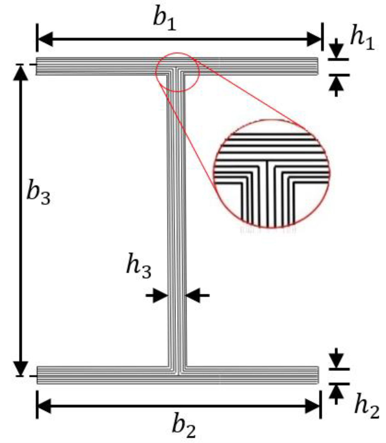
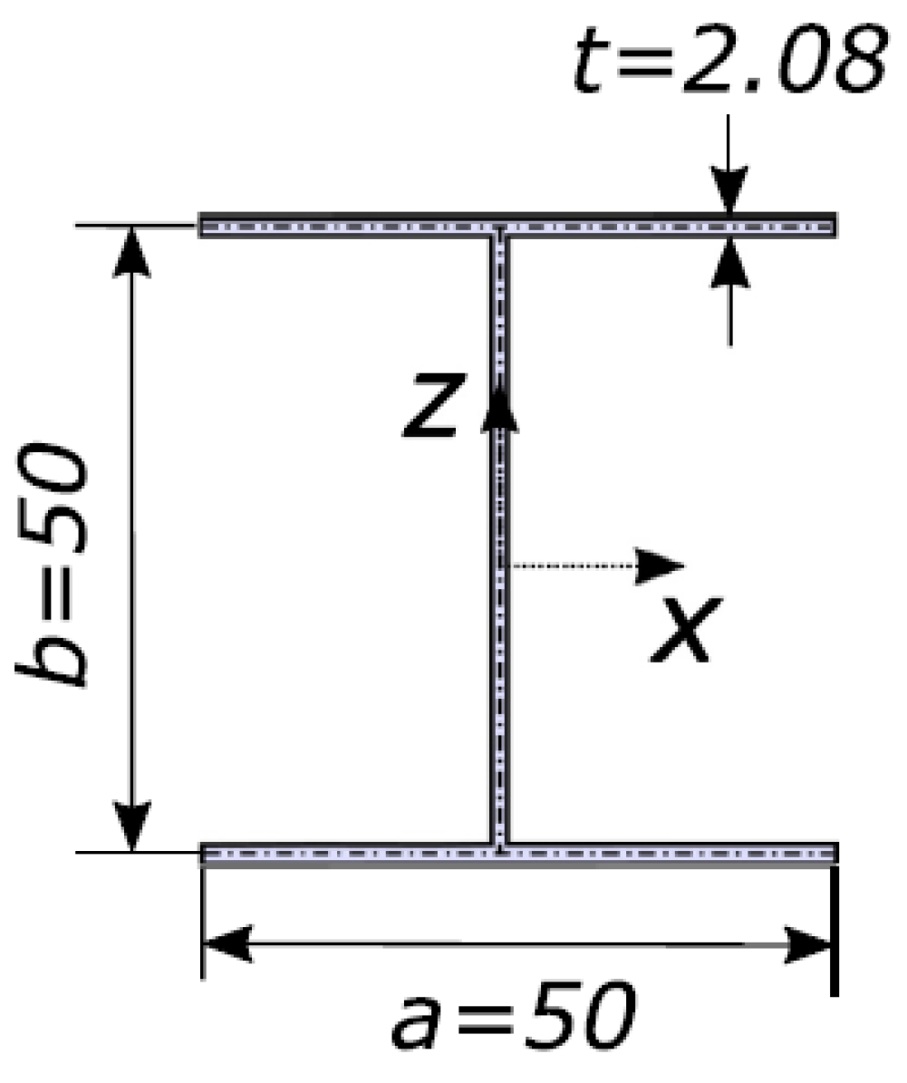
The composite material of metal–ceramic Al/Al2O3 is adopted with the following material properties: E m = 70   G P a , ρ m = 2702   k g / m 3 , E c = 360   G P a ,   and ρ c = 3960   k g / m 3 . Poisson’s ratio is supposed to be v = 0.3 . The length of the beam is l = 1   m . Geometric parameters are provided as h 1 = h 2 = h 3 = h = 2   m m ; b 1 = b 2 = 35   m m ; and b 3 = 44.5 mm, as shown in Figure 15.
For convenience, the dimensionless natural frequency is given as follows:
ω ¯ = ω L 2 b 3 ρ c E m
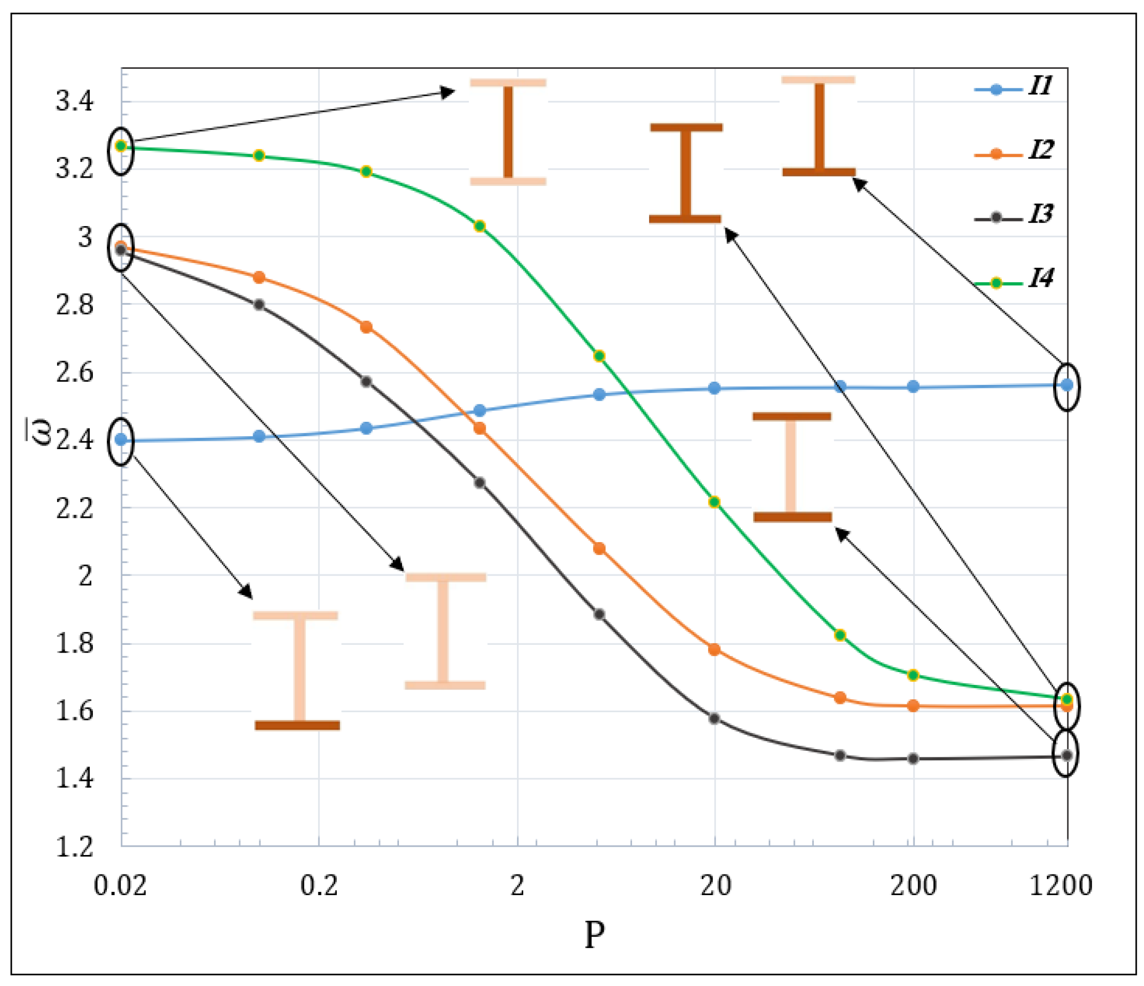
In order to investigate the effect of the graded law, the dimensionless fundamental frequency ω ¯ 1 of the S–S FGM beams for various types of materials is plotted in Figure 16. The first dimensionless natural frequencies are given for different power law indexes p and boundary conditions. The numerical results presented in Table 4, Table 5 and Table 6 show good agreement of the RBT models with the 3D FEM model for the first two dimensionless natural frequencies (especially the first mode).
By comparing the cross-sections studied in this work (Table 4, Table 5 and Table 6), it can be seen that the dimensionless natural frequency values in section I 4 are greater than in the other sections for p < 5, while the dimensionless natural frequency values in section I 3 are less than those obtained in the rest of the sections as p becomes higher. It seems that the natural frequencies are low-sensitive to the value of p for section I 1 under the S–S and C–F boundary conditions, where the decrease in p values is followed by an increase in the frequency value. One can observe that the material distribution has a considerable effect on the bending–torsional dimensionless natural frequencies of thin-walled FGM beams under all the boundary conditions, although the web of the beam is more sensitive to this effect. When approaching homogenous metal for web, the inherent frequency yields to bigger vibrations.
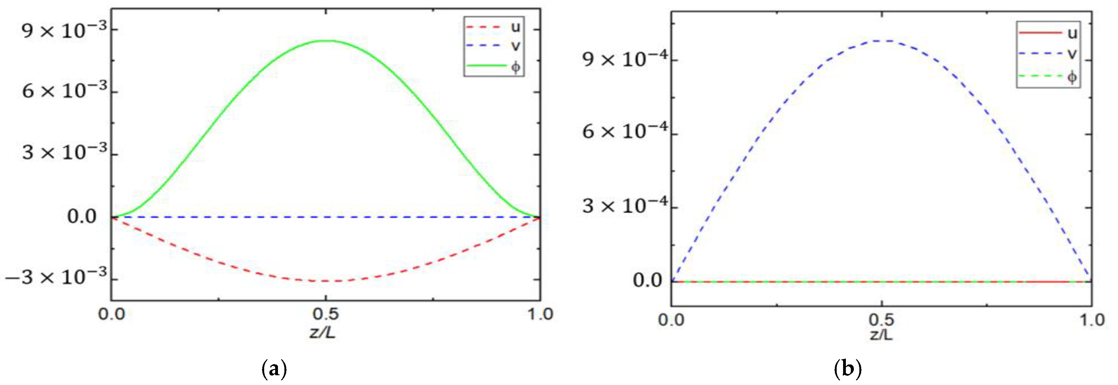
Figure 17 illustrates the first four of the corresponding mode shapes of the simply-supported FG beam with section   I 2 for the RBT model when p = 1.3. These figures show that the bending frequency appears in the second mode (in the y-direction), and the torsion in the third mode, i.e., the modes have non-coupled vibration. While the bending–torsional (coupled) mode appears in the first and fourth modes (bending mode in the x-direction and torsional mode), it is shown that the effect of the material distribution is the dominant factor in the vibration characteristics of an I-section beam.
In order to illustrate the contribution of distortion (in-plane distortion) in the vibration mode, let us consider the homogenous cantilever I-beam (full ceramic). Figure 18 shows a comparison between the RBT models and 3D FEM in terms of numerical values and mode shapes. The contribution of the distortion of the cross-section (in-plane) (Figure 15, Shape 1) along the beam of the RBT* model and 3D FEM can be clearly seen, with a good fit in the mode value ( 36.309 ; 36.296). This confirms the natural contribution of the sectional distortion in the 3D mode shape and shows that the RBT vibration mode is quite acceptable. It can also be verified that all vibration modes correspond to the same general mode, as defined by the differences in the preponderant generalized displacement states in Figure 18c,d.

6. Conclusions

In this paper, the free vibration of the bending–torsion problem of thin-walled beams with FGMs is studied using the RBT models built on the 3D SV solution. The displacement field of the kinematic models contains the main deformation modes associated with the 6 cross-sectional stresses, which are provided by the 3D SV solution, as well as the displacement modes of the cross-section which reflect its warpings in and out of the plane. These modes lead to a beam theory that really corresponds with the nature of the cross-section (shape and materials). In order to apply RBT/SV, a CSB tool is used which consists of two tools, CSection and CBeam (which complement each other). CSection calculates the mechanical characteristics of the cross-section using 2D finite elements, and then CBeam uses the cross-section to calculate the beam using 1D finite elements.
In order to evaluate the RBT models, the free vibrations of thin-walled I-shaped beam problems have been analyzed, and the obtained results were compared with the literature. The results obtained from RBT models showed a close correlation between the results of the current work and the results of previous work for a thin-walled laminated composite beam, which confirms the accuracy of the proposed method. Various calculations of I-sections have been carried out with different boundary conditions to obtain the bending, torsional, and coupled bending–torsional modes of the FGM beam with anisotropic materials. It is found that the power index and the symmetry of the materials have a significant influence, and the web material has a crucial role on the natural frequency. In addition, the dimensionless natural frequencies and mode shapes of thin-walled beams using different types of FGM beams obtained through the present models (RBT and RBT*) indicate good agreement with 3D FEM calculations. It can be concluded that the RBT models have good capabilities for modeling thin-walled FGM beams for vibration analysis, depending on the continuity of the proposed ceramic–metal materials, making them more feasible and practicable. In addition, the CPU time for RBT models with the CSB tool is very short compared to 3D FEM, and closer compared to other simpler models.

Author Contributions

Conceptualization, I.G. and M.G.; methodology, P.V.; software, I.G.; validation, I.G., M.K. and M.G.; formal analysis, I.G.; investigation, P.V.; resources, I.G.; data curation, P.V.; writing—original draft preparation, I.G.; writing—review and editing, P.V.; visualization, I.G.; supervision, M.G.; project administration, I.G. All authors have read and agreed to the published version of the manuscript.

Funding

This research received no external funding.

Data Availability Statement

The original contributions presented in the study are included in the article, further inquiries can be directed to the corresponding authors.

Conflicts of Interest

The authors declare no conflict of interest.

References

  1. Koizumi, M. FGM activities in Japan. Compos. B Eng. 1997, 28, 1–4. [Google Scholar] [CrossRef]
  2. Koizumi, M.; Niino, M. Overview of FGM research in Japan. MRS Bull. 1995, 20, 19–21. [Google Scholar] [CrossRef]
  3. Kawasaki, A.; Watanabe, R. Concept and P/M fabrication of functionally gradient materials. Ceram. Int. 1997, 23, 73–83. [Google Scholar] [CrossRef]
  4. Ali, E.; Woldeyes, K.; Urgessa, G. Fire performance of functionally-graded-material sheathed load bearing thin-walled structural framing. Fire Saf. J. 2021, 125, 103425. [Google Scholar] [CrossRef]
  5. Reddy, J.N. Analysis of functionally graded plates. Int. J. Numer. Methods Eng. 2000, 47, 663–684. [Google Scholar] [CrossRef]
  6. Bodaghi, M.; Saidi, A.R. Levy-type solution for buckling analysis of thick functionally graded rectangular plates based on the higher-order shear deformation plate theory. Appl. Math. Model. 2010, 34, 3659–3673. [Google Scholar] [CrossRef]
  7. Sofiyev, A.H. The vibration and stability behavior of freely supported FGM conical shells subjected to external pressure. Compos. Struct. 2009, 89, 356–366. [Google Scholar] [CrossRef]
  8. Sofiyev, A. Buckling analysis of FGM circular shells under combined loads and resting on the Pasternak type elastic foundation. Mech. Res. Commun. 2010, 37, 539–544. [Google Scholar] [CrossRef]
  9. Ke, L.-L.; Wang, Y.-S. Size effect on dynamic stability of functionally graded microbeams based on a modified couple stress theory. Compos. Struct. 2011, 93, 342–350. [Google Scholar] [CrossRef]
  10. Nateghi, A.; Salamat-talab, M.; Rezapour, J.; Daneshian, B. Size dependent buckling analysis of functionally graded micro beams based on modified couple stress theory. Appl. Math. Model. 2012, 36, 4971–4987. [Google Scholar] [CrossRef]
  11. Neves, A.M.A.; Ferreira, A.; Carrera, E.; Cinefra, M.; Roque, C.; Jorge, R.M.N.; Soares, C.M.M. Static, free vibration and buckling analysis of isotropic and sandwich functionally graded plates using a quasi-3D higher-order shear deformation theory and a meshless technique. Compos. B Eng. 2013, 44, 657–674. [Google Scholar] [CrossRef]
  12. Barati, M.R.; Shahverdi, H. Aero-hygro-thermal stability analysis of higher-order refined supersonic FGM panels with even and uneven porosity distributions. J. Fluids Struct. 2017, 73, 125–136. [Google Scholar] [CrossRef]
  13. Wang, Y.; Feng, C.; Zhao, Z.; Yang, J. Eigenvalue buckling of functionally graded cylindrical shells reinforced with graphene platelets (GPL). Compos. Struct. 2018, 202, 38–46. [Google Scholar] [CrossRef]
  14. Mahmoudi, A.; Benyoucef, S.; Tounsi, A.; Benachour, A.; Bedia, E.A.A.; Mahmoud, S.R. A refined quasi-3D shear deformation theory for thermo-mechanical behavior of functionally graded sandwich plates on elastic foundations. J. Sandw. Struct. Mater. 2019, 21, 1906–1929. [Google Scholar] [CrossRef]
  15. El-Ashmawy, A.M.; Xu, Y. Longitudinal modeling and properties tailoring of functionally graded carbon nanotube reinforced composite beams: A novel approach. Appl. Math. Model. 2020, 88, 161–174. [Google Scholar] [CrossRef]
  16. Sun, S.; Zhang, X.; Li, X. A consistent shear beam theory for free vibration of functionally graded beams based on physical neutral plane. Mech. Adv. Mater. Struct. 2023, 31, 3844–3854. [Google Scholar] [CrossRef]
  17. Turan, M.; Adiyaman, G. A New Higher-Order Finite Element for Static Analysis of Two-Directional Functionally Graded Porous Beams. Arab. J. Sci. Eng. 2023, 48, 13303–13321. [Google Scholar] [CrossRef]
  18. Van Vinh, P.; Van Chinh, N.; Tounsi, A. Static bending and buckling analysis of bi-directional functionally graded porous plates using an improved first-order shear deformation theory and FEM. Eur. J. Mech. A/Solids 2022, 96, 104743. [Google Scholar] [CrossRef]
  19. Boumezbeur, K.; Khebizi, M.; Guenfoud, M.; Guendouz, I. Mechanical Response of Thin Composite Beams Made of Functionally Graded Material Using Finite Element Method. Period. Polytech. Civ. Eng. 2023, 67, 970–982. [Google Scholar] [CrossRef]
  20. Guendouz, I.; Guenfoud, H.; Khebizi, M.; Boumezbeur, K.; Guenfoud, M. Buckling analysis of thin-walled laminated composite or functionally graded sandwich I-beams using a refined beam theory. Mech. Based Des. Struct. Mach. 2024, 1–21. [Google Scholar] [CrossRef]
  21. Şimşek, M.; Kocatürk, T. Free and forced vibration of a functionally graded beam subjected to a concentrated moving harmonic load. Compos. Struct. 2009, 90, 465–473. [Google Scholar] [CrossRef]
  22. Larbi, L.O.; Kaci, A.; Houari, M.S.A.; Tounsi, A. An Efficient Shear Deformation Beam Theory Based on Neutral Surface Position for Bending and Free Vibration of Functionally Graded Beams. Mech. Based Des. Struct. Mach. 2013, 41, 421–433. [Google Scholar] [CrossRef]
  23. Shahba, A.; Attarnejad, R.; Marvi, M.T.; Hajilar, S. Free vibration and stability analysis of axially functionally graded tapered Timoshenko beams with classical and non-classical boundary conditions. Compos. B Eng. 2011, 42, 801–808. [Google Scholar] [CrossRef]
  24. Sankar, B.V. An elasticity solution for functionally graded beams. Compos. Sci. Technol. 2001, 61, 689–696. [Google Scholar] [CrossRef]
  25. Thai, H.-T.; Vo, T.P. Bending and free vibration of functionally graded beams using various higher-order shear deformation beam theories. Int. J. Mech. Sci. 2012, 62, 57–66. [Google Scholar] [CrossRef]
  26. Hadji, L.; Khelifa, Z.; El Abbes, A.B. A new higher order shear deformation model for functionally graded beams. KSCE J. Civ. Eng. 2016, 20, 1835–1841. [Google Scholar] [CrossRef]
  27. Şimşek, M. Fundamental frequency analysis of functionally graded beams by using different higher-order beam theories. Nucl. Eng. Des. 2010, 240, 697–705. [Google Scholar] [CrossRef]
  28. Aydogdu, M.; Taskin, V. Free vibration analysis of functionally graded beams with simply supported edges. Mater. Des. 2007, 28, 1651–1656. [Google Scholar] [CrossRef]
  29. Kadoli, R.; Akhtar, K.; Ganesan, N. Static analysis of functionally graded beams using higher order shear deformation theory. Appl. Math. Model. 2008, 32, 2509–2525. [Google Scholar] [CrossRef]
  30. Li, X.-F.; Wang, B.-L.; Han, J.-C. A higher-order theory for static and dynamic analyses of functionally graded beams. Arch. Appl. Mech. 2010, 80, 1197–1212. [Google Scholar] [CrossRef]
  31. Wattanasakulpong, N.; Prusty, B.G.; Kelly, D.W. Thermal buckling and elastic vibration of third-order shear deformable functionally graded beams. Int. J. Mech. Sci. 2011, 53, 734–743. [Google Scholar] [CrossRef]
  32. Giunta, G.; Belouettar, S.; Carrera, E. Analysis of FGM beams by means of classical and advanced theories. Mech. Adv. Mater. Struct. 2010, 17, 622–635. [Google Scholar] [CrossRef]
  33. Giunta, G.; Belouettar, S.; Carrera, E. Analysis of FGM beams by means of a unified formulation. In IOP Conference Series: Materials Science and Engineering; IOP Publishing: Bristol, UK, 2010; p. 12073. [Google Scholar]
  34. Vlasov, V.Z. Thin-walled elastic beams. PST Cat. 1961, 428. [Google Scholar]
  35. Dos Reis, H.L.M.; Goldman, R.B.; Verstrate, P.H. Thin-walled laminated composite cylindrical tubes: Part III—Bending analysis. J. Compos. Technol. Res. 1987, 9, 58–62. [Google Scholar]
  36. Lee, J.; Kim, S.-E. Flexural–torsional coupled vibration of thin-walled composite beams with channel sections. Comput. Struct. 2002, 80, 133–144. [Google Scholar] [CrossRef]
  37. Mohri, F.; Azrar, L.; Potier-Ferry, M. Vibration analysis of buckled thin-walled beams with open sections. J. Sound Vib. 2004, 275, 434–446. [Google Scholar] [CrossRef]
  38. Lee, J.; Kim, S.-E. Free vibration of thin-walled composite beams with I-shaped cross-sections. Compos. Struct. 2002, 55, 205–215. [Google Scholar] [CrossRef]
  39. El Fatmi, R. A refined 1D beam theory built on 3D Saint-Venant’s solution to compute homogeneous and composite beams. J. Mech. Mater. Struct. 2016, 11, 345–378. [Google Scholar] [CrossRef]
  40. Lahmar, M.; Naccache, F.; El Fatmi, R. Thermo-mechanical analysis of composite beams. Compos. Struct. 2017, 162, 388–400. [Google Scholar] [CrossRef]
  41. Naccache, F.; El Fatmi, R. Numerical free vibration analysis of homogeneous or composite beam using a refined beam theory built on Saint Venant’s solution. Comput. Struct. 2018, 210, 102–121. [Google Scholar] [CrossRef]
  42. Ilies, G.; Hamza, G.; Mohamed, G.; Mourad, K.; El Fatmi, R. Bending-torsional behavior analysis using a refined beam theory. Rugc 2021, 39, 2019–2022. [Google Scholar]
  43. Phi, L.T.M.; Nguyen, T.T.; Lee, J. Buckling analysis of open-section beams with thin-walled functionally graded materials along the contour direction. Eur. J. Mech. A/Solids 2021, 88, 104217. [Google Scholar] [CrossRef]
  44. Nguyen, T.-T.; Kim, N.-I.; Lee, J. Free vibration of thin-walled functionally graded open-section beams. Compos. B Eng. 2016, 95, 105–116. [Google Scholar] [CrossRef]
  45. Nguyen, T.T.; Thang, P.T.; Lee, J. Flexural-torsional stability of thin-walled functionally graded open-section beams. Thin-Walled Struct. 2017, 110, 88–96. [Google Scholar] [CrossRef]
  46. Guendouz, I.; Khebizi, M.; Guenfoud, H.; Guenfoud, M.; El Fatmi, R. Analysis of torsional-bending FGM beam by 3D Saint-Venant refined beam theory. Struct. Eng. Mech. 2022, 84, 423. [Google Scholar]
  47. Guendouz, I.; Khebizi, M.; Guenfoud, H.; Guenfoud, M. Analysis of FGM Cantilever Beams under Bending-torsional Behavior Using a Refined 1D Beam Theory. Period. Polytech. Civ. Eng. 2022, 66, 1262–1277. [Google Scholar] [CrossRef]
  48. El Fatmi, R.; Zenzri, H. On the structural behavior and the Saint Venant solution in the exact beam theory: Application to laminated composite beams. Comput. Struct. 2002, 80, 1441–1456. [Google Scholar] [CrossRef]
  49. El Fatmi, R. A Matlab tool to compute the mechanical characteristics of any composite section. Rev. Des Compos. Des Matériaux Avancés–No 2012, 395, 413. [Google Scholar]
  50. Guenfoud, H.; Ziou, H.; Himeur, M.; Guenfoud, M. Analyses of a composite functionally graded material beam with a new transverse shear deformation function. J. Appl. Eng. Sci. Technol. 2016, 2, 105–113. [Google Scholar] [CrossRef]
  51. Ziou, H.; Guenfoud, M.; Guenfoud, H. A simple higher-order shear deformation theory for static bending analysis of functionally graded beams. Jordan J. Civ. Eng. 2021, 15, 209–224. [Google Scholar]
  52. Naccache, F.; El Fatmi, R. Buckling analysis of homogeneous or composite I-beams using a 1D refined beam theory built on Saint Venant’s solution. Thin-Walled Struct. 2018, 127, 822–831. [Google Scholar] [CrossRef]
  53. Sheikh, A.H.; Asadi, A.; Thomsen, O.T. Vibration of thin-walled laminated composite beams having open and closed sections. Compos. Struct. 2015, 134, 209–215. [Google Scholar] [CrossRef]
  54. Vo, T.P.; Lee, J. Flexural-torsional coupled vibration and buckling of thin-walled open section composite beams using shear-deformable beam theory. Int. J. Mech. Sci. 2009, 51, 631–641. [Google Scholar] [CrossRef]
  55. Nguyen, N.D.; Nguyen, T.K.; Vo, T.P.; Nguyen, T.N.; Lee, S. Vibration and buckling behaviours of thin-walled composite and functionally graded sandwich I-beams. Compos. B Eng. 2019, 166, 414–427. [Google Scholar] [CrossRef]
  56. Kim, N.I.; Shin, D.K.; Park, Y.S. Dynamic stiffness matrix of thin-walled composite I-beam with symmetric and arbitrary laminations. J. Sound Vib. 2008, 318, 364–388. [Google Scholar] [CrossRef]
  57. Yang, H.; Daneshkhah, E.; Augello, R.; Xu, X.; Carrera, E. Numerical vibration correlation technique for thin-walled composite beams under compression based on accurate refined finite element. Compos. Struct. 2022, 280, 114861. [Google Scholar] [CrossRef]
Figure 1. A cantilever composite beam.
Jcs 09 00019 g001
Figure 2. Variation of Young’s modulus through the contour direction of an E–FGM beam.
Jcs 09 00019 g002
Figure 3. Cross-section deformations ( M s v i ): Poisson’s effect and out-of-plane warpings for a thin-walled laminated composite beam with orientation   15 / 15 4 s .
Jcs 09 00019 g003
Figure 4. Cross-section deformations ( M s v i ): Poisson’s effect and out-of-plane warpings for a composite beam with laminations (60).
Jcs 09 00019 g004
Figure 5. Cross-section deformations ( M s v i ): Poisson’s effect and out-of-plane warpings for a homogeneous and an FGM I-beam (p = 1.3).
Jcs 09 00019 g005
Figure 6. Cross-section deformations   ( D V j ) : distortion modes for a thin-walled laminated composite beam with orientation   15 / 15 4 s .
Jcs 09 00019 g006
Figure 7. Cross-section deformations   ( D V j ) : distortion modes for a composite beam with laminations (60).
Jcs 09 00019 g007
Figure 8. Cross-section deformations   ( D V j ) : distortion modes for a homogeneous and an FGM I-beam (p = 1.3).
Jcs 09 00019 g008
Figure 9. Thin-walled laminated composite I-beam.
Jcs 09 00019 g009
Figure 10. Variation of the fundamental frequencies (Hz) of thin-walled C–C I-beams: comparison between RBT models, Ngoc et al. [55] and Kim et al. [56].
Jcs 09 00019 g010
Figure 11. Geometry of a thin-walled I-shaped beam (dimensions in mm).
Jcs 09 00019 g011
Figure 12. First 10 mode shapes of the I-shaped composite beam with (30) lamination and C–F edge conditions based on the RBT model.
Jcs 09 00019 g012
Figure 13. Types of material distributions for web and flange.
Jcs 09 00019 g013
Figure 14. Four types of I-shaped FGM beams.
Jcs 09 00019 g014
Figure 15. Geometries of an I-shaped cross-section.
Jcs 09 00019 g015
Figure 16. The fundamental dimensionless natural frequency of simply supported I-shaped FGM beams according to RBT with respect to the power law P.
Jcs 09 00019 g016
Figure 17. Mode shapes in type I 1 for simply-supported (S–S) with p = 1.3. (a) mode 1 ω ¯ 1 = 2.451 , (b) mode 2 ω ¯ 2 = 7.532 , (c) mode 3 ω ¯ 3 = 8.523 ,   a n d (d) mode 4 ω ¯ 4 = 9.523 .
Jcs 09 00019 g017aJcs 09 00019 g017b
Figure 18. Global vibration mode for the C–F homogenous (ceramic) I-beam and variations of the preponderant u y , ω x , η M y , η d i s t ,   where η M y and η d i s t are associated with the M y -SV mode and the in-plane distortion mode.
Jcs 09 00019 g018
Table 1. Natural frequencies of a simply supported (S–S) thin-walled laminated composite I-beam (Hz).
BCsReferenceLay-Up
[ 0 ] 16 15 / 15 4 s 30 / 30 4 s 45 / 45 4 s 60 / 60 4 s 75 / 75 4 s 90 / 90 4 s
Present (RBT)24.49023.25020.00616.70014.80614.26814.160
Present (RBT*)24.49123.25320.00416.70014.80814.26814.162
S–SSheikh et al. [53] (Shear)24.16022.97019.80016.48014.66014.07013.960
Vo and Lee [54] (Shear)24.15022.95519.71916.44614.62714.04213.937
Ngoc et al. [55] (Shear)24.16922.97719.80616.48114.66814.07113.964
Ngoc et al. [55] (No Shear)24.19823.00119.82016.49014.66014.07913.972
Kim et al. [56] (No Shear)24.19422.99719.81616.48714.66614.07713.970
Table 2. Material properties of the thin-walled composite I-beam.
E 1 ( G P a ) E 2 ( G P a ) G 12 ( G P a ) v 12 ρ ( k g / m 3 )
53.7817.938.960.251968.9
Table 3. Estimation of the first ten natural frequencies ( H z ) of the composite I-beam (C–F), according to the different models available in the literature.
Mode Number ( 0 ) Lamination (60) Lamination
RBTRBT*CUF-LE [57] Abaqus [57]RBTRBT*CUF-LE [57] Abaqus [57]
Mode 134.8734.8434.3634.3620.9720.9620.8320.68
Mode 249.5549.4448.4547.7836.8736.8738.3038.41
Mode 360.6860.6562.9863.0342.5542.3840.9141.21
Mode 4213.91213.54211.38209.75130.43130.36129.38128.52
Mode 5236.46233.94230.05228.05220.54170.36162.26162.57
Mode 6340.18337.70 d348.77347.48171.70 *220.15 d228.31230.35
Mode 7579.88576.58 d512.89505.47360.86360.23353.61353.79
Mode 8611.51594.00522.66512.18414.76409.26387.17386.31
Mode 9833.08626.80547.02536.28577.64572.90 d538.53600.26
Mode 101088.10807.38 d570.67562.32695.19692.36 d559.06660.61
( ) d Distortional mode. ( ) * Mode 6 appeared in 5th position.
Table 4. The first two dimensionless natural frequencies of I-shaped FGM beams (C–F).
BCsSectionN-FsTheoryP-FGM
00.020.10.351.35.220852001200
RBT0.8580.8600.8630.8730.8930.9110.9140.9150.9150.916
ω ¯ 1 RBT*0.8550.8570.8610.8710.8900.9080.9120.9130.9130.914
3D FEM0.8560.8580.8620.8720.8910.9100.9130.9140.9140.915
I 1 RBT2.6442.6062.5572.4442.2412.1672.1732.1752.1752.176
ω ¯ 2 RBT*2.6442.6062.5572.4442.2412.1662.1732.1752.1752.175
3D FEM2.6492.6102.5612.4492.2462.1712.1762.1782.1782.179
RBT1.0801.0451.0280.9850.8700.7260.6540.6470.6430.643
ω ¯ 1 RBT*1.0771.0411.0250.9490.8680.7240.6520.6450.6420.641
3D FEM1.0791.0431.0270.9830.8690.7250.6530.6460.6430.641
I 2 RBT3.3323.2803.2233.0712.6862.2921.9341.8781.8721.871
ω ¯ 2 RBT*3.3323.1813.2223.0712.6862.2921.9341.8771.8711.870
C–F 3D FEM3.3383.2823.2253.0732.6892.2941.9371.8801.8741.872
RBT1.0801.0170.9660.8720.6660.5570.5320.5210.5180.517
ω ¯ 1 RBT*1.0771.0140.9620.8700.6630.5550.5290.5190.5160.515
3D FEM1.0791.0160.9650.8710.6630.5550.5300.5200.5170.515
I 3 RBT3.3323.2683.2223.0872.7542.3512.2022.1942.1942.191
ω ¯ 2 RBT*3.3323.2683.2223.0872.7542.3502.2022.1942.1942.191
3D FEM3.3383.2743.2283.0932.7602.3572.2082.2002.1982.197
RBT1.1611.1611.1571.1391.0680.8840.7490.7010.6900.677
ω ¯ 1 RBT*1.1581.1571.1541.1361.0650.8810.7460.6990.6890.675
3D FEM1.1611.1611.1561.1381.0670.8830.7480.7000.6900.676
I 4 RBT3.2503.1893.1523.0332.6872.1421.9091.8981.8911.890
ω ¯ 2 RBT*3.2503.1893.1523.0332.6862.1411.9091.8981.9241.890
3D FEM3.1653.1253.0953.0032.6322.1211.9101.8891.8911.890
Table 5. The first two dimensionless natural frequencies of I-shaped FGM beams (C–S).
BCsSectionN-FsTheoryP-FGM
00.020.10.351.35.220852001200
RBT3.6073.6283.6443.6803.7473.7983.7793.7493.7483.748
ω ¯ 1 RBT*3.5943.6173.6323.6673.7353.7863.7713.7463.7463.746
3D FEM3.4783.4883.4993.5273.5673.6023.5503.5403.5383.537
I 1 RBT8.4798.4478.4248.3338.1197.9007.8227.8057.8057.805
ω ¯ 2 RBT*8.4538.4208.3978.3048.0877.8627.7967.7797.7787.778
3D FEM7.4187.3957.3367.2056.9176.7836.5806.5586.5526.552
RBT4.7294.5774.5004.2783.6723.0392.7962.7752.7742.774
ω ¯ 1 RBT*4.7114.5464.4694.2473.6413.0252.7832.7652.7622.762
3D FEM4.7244.5594.4824.2603.6543.0292.7872.7652.7642.764
I 2 RBT11.13610.41210.2759.8188.6957.3116.8666.6966.6306.627
ω ¯ 2 RBT*11.11310.39210.2579.8038.6847.2966.8476.6776.6116.610
C–S 3D FEM8.3228.1368.0147.6956.8495.7424.8334.7064.6974.697
RBT4.7294.3864.2373.8262.9192.3012.2592.2602.2602.260
ω ¯ 1 RBT*4.7114.3614.2123.8012.8942.2762.2442.2452.2452.245
3D FEM4.7244.3744.2243.8132.9072.2892.2502.2512.2512.251
I 3 RBT11.13610.1959.9049.3828.3717.3757.2067.1547.1547.154
ω ¯ 2 RBT*11.11310.1829.8919.3688.3647.3637.1887.1367.1367.136
3D FEM8.3228.0657.9487.6166.8626.2076.0195.9965.9975.997
RBT5.0825.0775.0634.9844.6683.8653.2743.1963.1633.163
ω ¯ 1 RBT*5.0655.0605.0474.9674.6513.8523.2633.1853.1853.185
3D FEM5.0725.0675.0544.9744.6593.8563.2673.1893.1893.189
I 4 RBT10.68410.64610.60510.47610.0349.1177.2676.5076.4356.401
ω ¯ 2 RBT*10.66110.60110.55910.4319.9689.0397.2266.4746.3756.342
3D FEM7.5507.4967.4417.2736.7225.6595.0665.0134.9474.913
Table 6. The first two dimensionless natural frequencies of I-shaped FGM beams (C–C).
BCsSectionN-FsTheoryP-FGM
00.020.10.351.35.220852001200
RBT4.8244.8514.8684.9024.9514.9534.9344.9264.9234.918
ω ¯ 1 RBT*4.7954.8254.8434.8734.9234.9264.9114.9104.9084.907
3D FEM4.7224.7314.7384.7694.7984.8164.7234.7054.7014.700
I 1 RBT9.4839.4379.4099.3129.1198.9738.9668.9608.9588.957
ω ¯ 2 RBT*9.4389.3949.3679.2659.0698.9498.9268.9208.9188.917
3D FEM9.1309.1069.0498.9478.7368.6798.6378.5738.5728.572
RBT6.8826.6346.5066.1475.1544.2543.9833.9573.9193.950
ω ¯ 1 RBT*6.8306.5826.4546.0975.1034.2033.9323.9050.6163.899
3D FEM6.8676.6186.4916.1325.1394.2383.9673.9413.9363.935
I 2 RBT11.13610.44810.35110.0519.2607.8286.7046.4816.4606.451
ω ¯ 2 RBT*11.11310.42610.32810.0309.2397.8206.6926.4436.4536.445
C–C 3D FEM10.2409.9679.8219.4708.5657.1796.0935.9465.9385.932
RBT6.8826.3526.1315.5354.2213.3223.2883.2893.2903.290
ω ¯ 1 RBT*6.8306.2956.0805.4854.1713.2723.2583.2593.2593.259
3D FEM6.8876.3466.1375.5414.2263.3273.2693.2703.2703.270
I 3 RBT11.13610.79310.64010.0368.7807.9897.2657.2007.2017.201
ω ¯ 2 RBT*11.11310.75410.62910.0278.7767.9807.2587.1827.1827.182
3D FEM10.2409.7739.5939.0737.9137.0006.8046.7836.7838.557
RBT7.3917.3827.3477.2306.7645.6004.7534.6404.5894.582
ω ¯ 1 RBT*7.3417.3327.2977.1806.7145.5504.7034.6434.5874.586
3D FEM7.3767.3677.3327.2156.7495.5854.7384.6254.6054.598
I 4 RBT10.68410.64610.60510.4769.7758.4347.0036.8456.8316.831
ω ¯ 2 RBT*10.66110.60110.55910.4319.7548.4196.9926.8256.8066.806
3D FEM9.6539.5719.5159.3358.6977.3176.3916.2686.2516.251
Disclaimer/Publisher’s Note: The statements, opinions and data contained in all publications are solely those of the individual author(s) and contributor(s) and not of MDPI and/or the editor(s). MDPI and/or the editor(s) disclaim responsibility for any injury to people or property resulting from any ideas, methods, instructions or products referred to in the content.