Article

Performance of GFRP-Confined Rubberized Engineered Cementitious Composite Columns

1
Engineering Management Department, College of Engineering, Prince Sultan University, Riyadh 12435, Saudi Arabia
2
Structural Engineering Department, Faculty of Engineering, Zagazig University, Zagazig 44519, Egypt
3
Department of Engineering and Technology, Texas A&M University-Commerce, Commerce, TX 75429, USA
*
Author to whom correspondence should be addressed.
J. Compos. Sci. 2024, 8(8), 330; https://doi.org/10.3390/jcs8080330
Submission received: 15 July 2024 / Revised: 6 August 2024 / Accepted: 16 August 2024 / Published: 20 August 2024
(This article belongs to the Special Issue Polymer Composites and Fibers, Volume II)

Abstract

:
In coastal regions, the deterioration of structures and bridges due to environmental conditions and corrosion is a significant concern. To combat these issues, the use of corrosion-resistant materials like fiber-reinforced polymers (FRPs) materials, engineered cementitious composites (ECCs), and rubberized ECCs (RECC) shows promise as normal concrete (NC) alternatives by providing increased ductility and energy absorption properties. The effectiveness of confining concrete columns using GFRP tubes with ECC/RECC was assessed in this research by evaluating their performance through compression and push-out tests. The study explored key parameters such as GFRP tube thickness and the presence of shear connectors along the tube height, as well as examining various types of concrete. Additionally, a comprehensive parametric investigation utilizing finite element analysis (FEA) was conducted to analyze how different factors influence the behavior of confined concrete columns. These factors included the effect of GFRP tube thickness and diameter on the overall behavior of different types of confined concretes. The results demonstrate that GFRP tubes significantly enhance column capacity, while the presence of ECC/RECC exhibits even greater improvements in capacity, stiffness, and toughness compared to NC. This approach shows promise in reinforcing coastal infrastructure and addressing corrosion-related concerns effectively.

1. Introduction

In coastal regions, environmental conditions can lead to significant deterioration of coastal structures and bridges and an alarming increase in the corrosion of their reinforcing steel [1,2,3]. To mitigate these challenges, it is crucial to explore the use of corrosion-resistant materials, such as fiber-reinforced polymers (FRPs), which can serve both as a protective layer and a confinement layer for concrete columns.
In recent years, FRPs have gained significant traction in various civil engineering applications, particularly in challenging corrosive settings [4,5,6,7]. The appeal of FRPs lies in their exceptional features, including high strength-to-weight ratio, remarkable durability, and ease of fabrication and handling [8,9]. A notable application of FRPs involves employing concrete-filled FRP tubes as the primary structural elements, notably seen in bridge piers, where they deliver substantial strength and stiffness to the construction. These advancements in FRP technology present promising opportunities for enhancing structural integrity and performance in corrosive environments [10,11,12,13]. Confining Concrete columns with GFRP may be an acceptable solution that could increase their capacity and stiffness while keeping an appropriate cost [14,15]. The provided concrete should ensure both flexibility and strength.
Moreover, accidents of vehicles colliding with bridge columns have increased, and thousands of vehicle occupants lose their lives annually as a result of these frequent accidents, and thousands suffer serious injuries and permanent disabilities suffered from them for the rest of their lives. When a collision occurs between the vehicle and the columns, the energy of the collision that is generated must be absorbed by one of them or by both of them. Therefore, it is necessary to improve the performance of bridges using energy-absorption columns that have a high capacity to absorb collision energy to reduce the overall damage in vehicles. Moreover, the observed local buckling failure mode in previous studies indicates that FRP full strength has not been achieved [16,17]. For this, thicker FRP tubes should be provided, but this will increase the cost [18].
Recently, the use of engineered cementitious composites (ECCs) is promising due to their improved ductility, durability, and tensile strength compared to normal concrete (NC) [7,19,20,21,22]. Moreover, the use of ECC could improve the flexural capacity and ductility of composite structures. On the other hand, more than a billion tires are being manufactured and consequently, meaning that the same number of tires are being removed from vehicles, resulting in the waste of tire rubber materials. The disposal of waste tires has become an environmental challenge that has attracted researchers’ attention all over the world [23]. Several investigations are being carried out concerning the utilization of waste rubber in the field of construction, such as highway pavement and lightweight concrete structures. Waste rubber can be used as an aggregate alternative in ECC to produce a new concrete type called rubberized ECC (RECC). Compared to traditional concrete, RECC shows lower unit weight and a suitable range of workability. Moreover, the use of RECC (especially that containing more than 30% of waste rubber) could improve both the flexural capacity and energy dissipation of structural elements, providing multiple advantages in the case of impact loads such as collisions and accidents [24,25,26,27]. Therefore, the use of rubberized concrete along with glass fiber reinforced polymers (GFRP) could improve the energy absorption of bridge columns and reduce the energy absorbed by vehicles to reduce injuries to the occupants of colliding vehicles. Moreover, the use of rubberized concrete as an infill could reduce deformation while maintaining an overall light weight.
This innovative approach, which combines both FRP tubes and ECC/RECC, not only addresses the urgent need to protect coastal infrastructure but also paves the way for sustainable and durable construction practices. The use of the proposed approach as a multifunctional solution holds immense potential to revolutionize the design and maintenance of coastal structures, offering a reliable and cost-effective strategy to combat corrosion and ensure the longevity of critical infrastructure in these challenging environments. Further research and practical implementation of FRP-based solutions are vital to bridge the existing gap and ensure the long-term performance and safety of coastal structures and bridges.
The research gap becomes evident due to the prevalence of bridges and infrastructure in coastal regions exposed to saltwater, leading to iron rust and concrete column corrosion. Additionally, many bridge columns, especially smaller ones, are susceptible to damage from vehicular accidents. Combining GFRP tubes and ECC/RECC presents an innovative approach to bolster the resilience of coastal structures while maintaining cost-effectiveness and sustainability. Therefore, there is a need for comprehensive studies to address these issues. This research seeks to explore the implementation of GFRP tubes and the utilization of ECC/RECC as sustainable solutions to enhance the efficiency and protection of these columns. The primary objectives are to improve energy absorption capabilities, prolong lifespan, and retain the advantage of lightweight construction without incurring additional costs. By investigating these novel approaches, this research aims to bridge the existing gap in knowledge and contribute to the sustainable development and resilience of coastal infrastructure.

2. Experimental Program

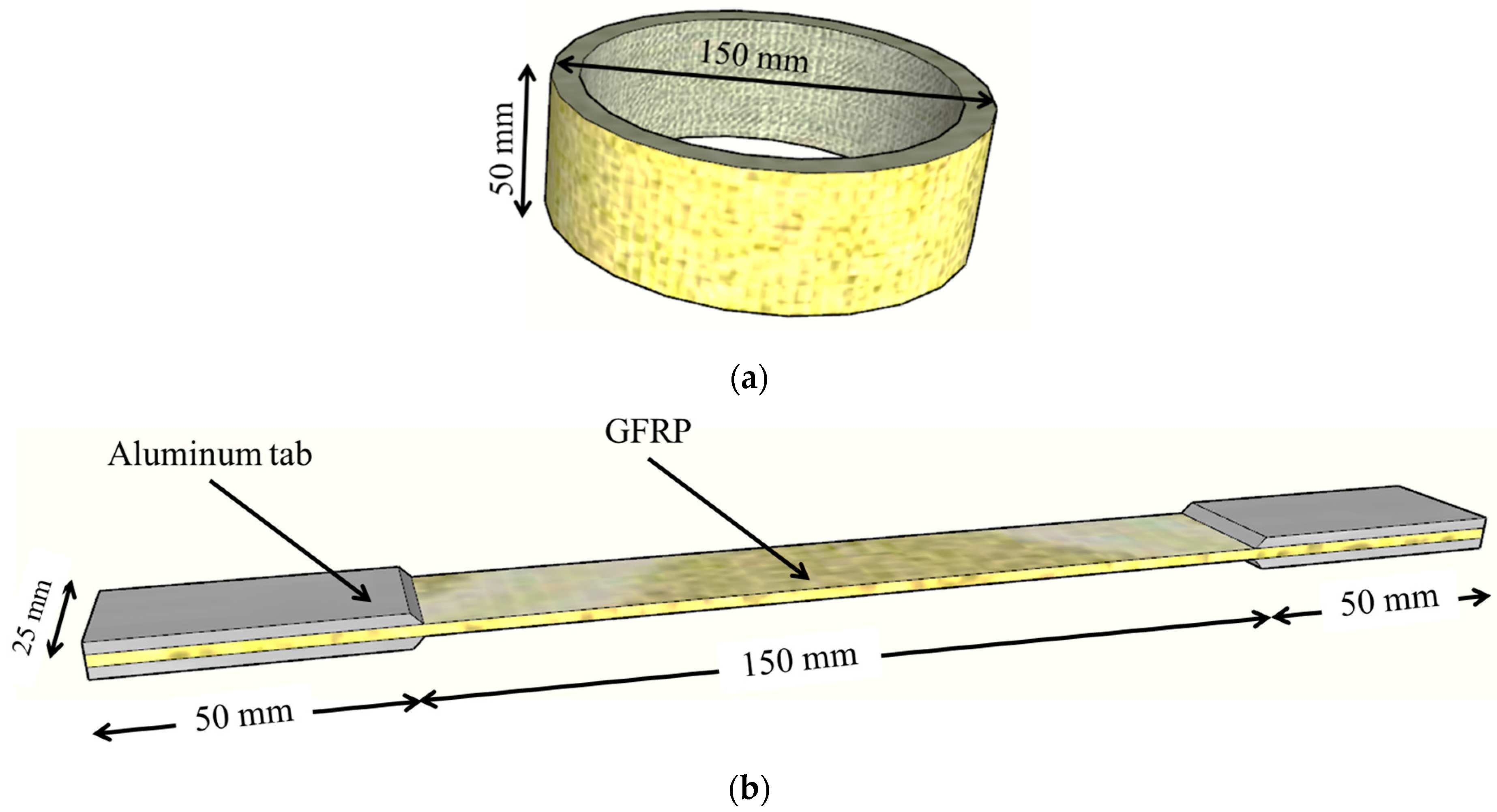
2.1. Specimen Details and Test Program

In the current experimental campaign, fifteen cylindrical specimens were cast from NC, ECC, and RECC and were divided into five groups, as shown in Table 1. Three concrete samples (two identical specimens for each concrete type) comprised the first group (G1), which served as the control group. Three cylindrical concrete specimens were cast in an 8-mm thick GFRP tube for confinement in the second group (G2). With the exception of the shear connectors attaching the GFRP tube to the concrete, the third group (G3) resembled the second group. According to Table 1, the third and fourth groups (G4 and G5) were comparable to the second and third groups, respectively. The primary distinction was that while groups G4 and G5 were exposed to the push-out loading regime, groups G2 and G3 were subjected to axial compression force up to failure.
Compression specimens were made of concrete cylinders, 150 mm in diameter and 400 mm in height, as shown in Figure 1a, whereas push-out specimens were 250 mm in height, as shown in Figure 1b. Additionally, as shown in Figure 1, certain specimens (G3 and G5) had shear connectors placed every 100 mm along the GFRP height to obtain a full-shear connection between the concrete and the GFRP tube. For push-out specimens, 20 mm of the GFRP base was left void of concrete to allow the concrete to sag under the push-out load.

2.2. Material Properties and Mix Proportions

Three concrete mixes were utilized in the current study (NC, ECC, and RECC). Mix proportions of each concrete type are presented in Table 2. Polyvinyl alcohol (PVA) fibers of 10 mm length were used for the production of the ECC with a percentage of 1% by volume of concrete, as illustrated in Table 2. Although the concrete mix of the RECC is similar to that of the ECC, recycled crumb rubber has been added as a new filler ingredient to reduce costs without sacrificing any of the ECC’s key characteristics. Moreover, choosing rubber as a filler instead of coarse material is said to preserved the soft characteristics that made ECC unique. In Table 2, the concrete compressive strengths were determined as the average value of three standard specimens.
To assess the properties of GFRP coupons under different conditions, tests were conducted to evaluate both tension and compression. For the tensile test, three specimens measuring 250 mm in length and 25 mm in width were utilized according to ASTM D3039 [28]. In contrast, three tubes measuring 150 mm in diameter and 30 mm in height were employed for the compression test, as illustrated in Figure 2. Compression test specimens had the same diameter as the main specimens but were shorter to prevent local buckling and ensure a pure compressive failure mode. The resulting stress-strain relationships from these tests are depicted in Figure 3.

2.3. Test Setup and Instrumentations

Tests were performed using a displacement-controlled rate of 0.5 mm/min, and specimens were tested under compression till failure. Specimens’ surfaces were polished and topped with a thin coating layer of high-strength plaster to ensure the uniform application of vertical force and to prevent premature failure. In the push-out tests, to allow vertical slipping, the load was applied to the concrete surface only, keeping the GFRP tube unloaded. To measure vertical displacement, the Linear Variable Displacement Transducer (LVDT) was positioned vertically as shown in Figure 4 which depicts the complete test setup and equipment.

3. Results and Discussion

3.1. Compression Test Results

In this section, the behavior of groups G1 to G3 was presented and discussed through axial load-shortening response. The E-control specimen (E-C) introduced better overall behavior as shown in Figure 5, which presents the response of G1 containing the control specimen for each concrete type. The observed increase in the initial stiffness and peak load were about 90% and 55%, respectively, compared to the N-control specimen (N-C). Despite the common undesirable compressive characteristics of rubberized concrete [25], combining rubberized concrete with ECC, in this research, resulted in closer behavior to that of N-C as shown in Figure 5. The peak strains (axial shortening/specimen length at the peak load) were improved tremendously and subsequently, E-C and RE-control (RE-C) specimens exhibited improvements in ductility, as presented in Figure 5b.
In general, confining different concrete types using GFRP tubes significantly enhanced the behavior of group G2 specimens compared to group G1 as shown in Figure 6. Similar to the E-C in group G1, the E-C exhibited higher stiffness and peak load compared to N-C and RE-C. On the other hand, the RE-C showed acceptable initial stiffness up to an axial load of about 500 kN; the contribution of GFRP started to appear after concrete cracking resulting in the resurrection of stiffness up to a peak load of 717.96 kN as shown in Figure 6. Concerning N-C, the observed peak load was 13% higher than that of RE-C and 10% lower than that of E-C.
Providing shear connectors to both E-C-S and RE-C-S increased their peak load by about 12% and 14%, respectively, compared to specimens without shear connectors as shown in Figure 7. The existence of the fibers provided additional resistance to micro-cracks in the concrete due to stress concentration at the shear connectors and subsequently maintained the bond strength between the concrete and GFRP. Moreover, the shear connectors reduced slippage along the interface between the concrete and GFRP. On the other hand, the existence of shear connectors in N-C-S resulted in almost no significant increase in peak load.
Figure 8 depicts the failure of all specimens examined experimentally. Traditional shear failure was found in the case of N-C, as illustrated in Figure 8a. The presence of PVA fiber changed the failure into a splitting tensile one in both E-C and RE-C, as seen in Figure 8b,c, respectively. In the case of specimens confined within GFRP tubes, NC displayed local buckling at the center of the GFRP tube, as illustrated in Figure 8a. On the other hand, the GFRP tube was split vertically for ECC and RECC, as illustrated in Figure 8b,c, which was consistent with the failure of their control specimens. Finally, regardless of the concrete type, the presence of shear connections causes a vertical fracture in the GFRP tube beginning at the bolts, with occasional horizontal cuts.
Figure 9 presents the toughness of tested specimens, which was calculated as the area under the experimental load-displacement curve. For all concrete types, confining the concrete with GFRP tubes improved the fracture toughness of the tested specimens. Moreover, providing shear connectors along the GFRP tubes had almost no effect on toughness compared to specimens with GFRP tubes only.

3.2. Push-Out Test Results

The results of push-out tests are presented in terms of axial load versus axial slip, as shown in Figure 10. Results revealed that regardless of the concrete type, specimens without shear connectors exhibited almost the same behavior, indicating that the concrete type did not affect the contact/friction between the concrete and the GFRP tube. On the other hand, the existence of shear connectors significantly enhanced resistance to slip between the concrete and the GFRP tube. The greatest enhancement was observed in the case of ECC followed by NC and RECC specimens as shown in Figure 10.

4. Numerical Simulation

In this paper, ABAQUS software Version 6.10 (2010) was employed to perform 3D Finite Element Modeling (FEM) to numerically simulate the experimentally tested specimens. Moreover, a parametric study was performed to investigate the effect of GFRP tube thickness and diameter on the overall behavior of different types of confined concretes.

4.1. FE Model Built-Up, Interaction, and Boundary Conditions

Dimensions of the FE models, for both compression and push-out models, were specified to match those of the specimens tested experimentally. The concrete cylinders, GFRP tubes, shear studs as well as loading plates were modeled using the eight-node linear solid elements with reduced integration (C3D8R), as shown in Figure 11. Surface-to-surface contact was employed to simulate the interaction between the concrete cylinders and the GFRP tubes and between the concrete and the shear studs. In this contact, Coulomb friction and hard contact properties were assigned in the tangent and normal directions, respectively.
The load was applied to a reference point connected to the top loading plate, while another reference point at the bottom plate was restrained against movement and rotation as shown in Figure 11. Each reference point was connected to its corresponding plate through a tie constraint.

4.2. Material Constitutive Modeling

The model developed by Carreira and Chu [29] was used to simulate the stress-strain behavior of NC (Figure 12), while the relationships proposed by Zhou et al. [30] and Aslani [31] were used to predict the stress-strain behaviors of ECC and RECC under compression and tension (Figure 13). For specimens having GFRP tubes, the confinement effect was considered according to the model proposed by Tao et al. [32]. Moreover, the Concrete Damage Plasticity (CDP) model was employed for the simulation of all types of concrete in the current study.

4.3. FE Model Verification

Three specimens, one from each group, were simulated through FE analysis, and their results were used in conjunction with experimental results to validate the accuracy of the simulations for different elements, concrete types, confinement, and bolts. As illustrated in Figure 14 and Figure 15, the FE findings were validated against experimental data in terms of the axial load versus axial shortening relationship and failure mechanisms. The FE results agree with the overall behavior at all loading levels of this test, indicating that this FE approach can be used to predict the overall behavior at the loading levels of this test.

5. Parametric Study

The generated finite element model was expanded in this part of the study to investigate the influence of GFRP tube thickness and diameter on the compression behavior of concrete confined within GFRP tubes on the compressive load-carrying capacity. The main studied parameters were concrete type (ECC and RECC), thickness of the GFRP tube (4, 6, 8, and 10 mm), and diameter of the GFRP tube (100, 150, and 200 mm), as listed in Table 3.
The effect of GFRP tube thickness on load-carrying capacity is illustrated in Figure 16 for both ECC and RECC specimens. Results revealed that the load-carrying capacity increased with increasing tube thickness as a result of the increased confinement. This increase was more significant in the case of RECC, showing that the use of a thicker GFRP tube (10 mm) could compensate for the reduction in the compression capacity due to rubber particles.
Figure 17 presents the effect of GFRP tube diameter on the load-carrying capacity of both ECC and RECC. Increasing the diameter from 100 mm to 150 mm and 200 mm increased the load-carrying capacity by about 30% and 106%, respectively, for ECC specimens. This increase was about 24% and 38%, respectively, for RECC. Moreover, as depicted in Figure 18, the initial stiffness of ECC and RECC increased by about 107% and 142%, respectively, due to the increase in specimen diameter from 100 mm to 200 mm.

6. Conclusions

This research evaluated the effectiveness of confining concrete columns with GFRP tubes through compression and push-out tests. It explores key parameters including GFRP tube thickness, shear connectors, and different concrete types. A comprehensive parametric study using finite element analysis examined the behavior of confined concrete columns. According to the study, the following points were highlighted:
  • As a result of confinement, GFRP tubes significantly enhanced column capacity, with ECC/RECC providing even greater improvements compared to standard NC in terms of fracture toughness.
  • ECC increased initial stiffness and peak load by about 90% and 55%, respectively, compared to N-C.
  • RECC exhibited comparable behavior to NC.
  • Concerning N-C, the observed peak load was 13% higher than that of RE-C and 10% lower than that of E-C.
  • The existence of fibers in E-C-S and RE-C-S provided with shear connectors increased peak load by about 12% and 14%, respectively, compared to specimens without shear connectors.
  • From the pushout test results, it can be concluded that changing the concrete type has an insignificant effect on contact/friction between concrete and GFRP tubes for specimens without shear connectors. On the other hand, providing the specimens with shear connectors significantly increases load-carrying capacity.
  • Increasing GFRP tube thickness resulted in greater confinement; indicating that load-carrying capacity can be increased by increasing tube thickness.

Author Contributions

Conceptualization, M.T.N.; data curation, M.Z. and A.E.-Z.; formal analysis, M.Z.; investigation, M.S., A.E.-Z. and M.E.; methodology, M.T.N., M.S. and M.E.; software, M.S., M.Z. and A.E.-Z.; supervision, M.T.N.; validation, M.S.; visualization, and M.E.; writing—original draft, M.S., M.Z. and M.E.; writing—review & editing, A.E.-Z. All authors have read and agreed to the published version of the manuscript.

Funding

This research received no external funding.

Data Availability Statement

The original contributions presented in the study are included in the article, further inquiries can be directed to the corresponding author.

Acknowledgments

The authors would like to thank Prince Sultan University for their support. Additionally, we extend our gratitude to Elsewedy EGYPLAST Company for their valuable support in supplying the testing materials.

Conflicts of Interest

The authors declare no conflicts of interest.

References

  1. Wang, Z.; Zhao, X.L.; Xian, G.; Wu, G.; Singh Raman, R.K.; Al-Saadi, S. Durability Study on Interlaminar Shear Behaviour of Basalt-, Glass- and Carbon-Fibre Reinforced Polymer (B/G/CFRP) Bars in Seawater Sea Sand Concrete Environment. Constr. Build. Mater. 2017, 156, 985–1004. [Google Scholar] [CrossRef]
  2. Ren, F.; Liu, T.; Chen, G.; Xie, P.; Xiong, M.X.; Yuan, T.; Chen, Y.; Guo, S. Flexural Behavior and Modelling of FRP-Bar Reinforced Seawater Sea Sand Concrete Beams Exposed to Subtropical Coastal Environment. Constr. Build. Mater. 2021, 309, 125071. [Google Scholar] [CrossRef]
  3. Jarek, A.; Dos Santos, A.T.; Bragança, M.O.G.P.; Pinkoski, I.M.; Neri, M.A.T.; Diniz, J.H.O.T.; Gomes, R.A.N. Experimental and Numerical Investigations to Evaluate the Structural Integrity of Concrete Beams Exposed to an Aggressive Coastal Environment. Structures 2022, 37, 795–806. [Google Scholar] [CrossRef]
  4. Van Den Einde, L.; Zhao, L.; Seible, F. Use of FRP Composites in Civil Structural Applications. Constr. Build. Mater. 2003, 17, 389–403. [Google Scholar] [CrossRef]
  5. Zhao, X.-L.; Bai, Y.; Al-Mahaidi, R.; Rizkalla, S. Effect of Dynamic Loading and Environmental Conditions on the Bond between CFRP and Steel: State-of-the-Art Review. J. Compos. Constr. 2013, 18, A4013005. [Google Scholar] [CrossRef]
  6. Emara, M.; Elkomy, N.; Hassan, H. Numerical Assessment of Reinforced Concrete Beams Strengthened with CFRP Sheets under Impact Loading. Frat. Integrità Strutt. 2021, 15, 48–64. [Google Scholar] [CrossRef]
  7. Emara, M.; El-Zohairy, A.; Fekry, M.; Husain, M. Effect of Using ECC Layer on the Flexural Performance of RC Beams Previously Strengthened with EB CFRP Laminates. Sustainability 2022, 14, 16990. [Google Scholar] [CrossRef]
  8. De Lorenzis, L.; Teng, J.G. Near-Surface Mounted FRP Reinforcement: An Emerging Technique for Strengthening Structures. Compos. Part B Eng. 2007, 38, 119–143. [Google Scholar] [CrossRef]
  9. Emara, M.; Torres, L.; Baena, M.; Barris, C.; Cahís, X. Bond Response of NSM CFRP Strips in Concrete under Sustained Loading and Different Temperature and Humidity Conditions. Compos. Struct. 2018, 192, 1–7. [Google Scholar] [CrossRef]
  10. Zaghi, A.E.; Saiidi, M.S.; Mirmiran, A. Shake Table Response and Analysis of a Concrete-Filled FRP Tube Bridge Column. Compos. Struct. 2012, 94, 1564–1574. [Google Scholar] [CrossRef]
  11. ElGawady, M.A.; Dawood, H.M. Analysis of Segmental Piers Consisted of Concrete Filled FRP Tubes. Eng. Struct. 2012, 38, 142–152. [Google Scholar] [CrossRef]
  12. Lin, S.; Zhang, B.; Zhang, S.; Cai, Z.; Lai, C.; Zhang, J. Behavior and Modeling of Large-Scale Concrete-Filled FRP Tubes with Longitudinal Steel Rebars under Lateral Impact Loading. Thin-Walled Struct. 2023, 186, 110691. [Google Scholar] [CrossRef]
  13. Bazli, M.; Dorothea Luck, J.; Rajabipour, A.; Arashpour, M. Bond-Slip Performance of Seawater Sea Sand Concrete Filled Filament Wound FRP Tubes under Cyclic and Static Loads. Structures 2023, 52, 889–903. [Google Scholar] [CrossRef]
  14. Qasrawi, Y.; Fam, A. Flexural Load Tests on New Spun-Cast Concrete-Filled Fiber-Reinforced Polymer Tubular Poles. Struct. J. 2008, 105, 750–759. [Google Scholar] [CrossRef]
  15. Mitchell, J.; Fam, A. Tests and Analysis of Cantilevered GFRP Tubular Poles with Partial Concrete Filling. J. Compos. Constr. 2009, 14, 115–124. [Google Scholar] [CrossRef]
  16. Masmoudi, R.; Mohamed, H.; Metiche, S. Finite Element Modeling for Deflection and Bending Responses of GFRP Poles. J. Reinf. Plast. Compos. 2008, 27, 639–658. [Google Scholar] [CrossRef]
  17. Nawar, M.T.; Kaka, M.E.; El-Zohairy, A.; Elhosseiny, O.; Arafa, I.T. Effect of Supporting Base System on the Flexural Behavior and Toughness of the Lighting GFRP Poles. Sustainability 2022, 14, 12614. [Google Scholar] [CrossRef]
  18. Desai, N.; Yuan, R. Investigation of Bending/Buckling Characteristics for FRP Composite Poles. In Proceedings of the Earth and Space 2006—Proceedings of the 10th Biennial International Conference on Engineering, Construction, and Operations in Challenging Environments, League City TX, USA, 5 March 2006; pp. 1–18. [Google Scholar] [CrossRef]
  19. Hamoda, A.; Abdelazeem, F.; Emara, M. Concentric Compressive Behavior of Hybrid Concrete–Stainless Steel Double-Skin Tubular Columns Incorporating High Performance Concretes. Thin-Walled Struct. 2020, 159, 107297. [Google Scholar] [CrossRef]
  20. Emara, M.; Mohamed, H.A.; Rizk, M.S.; Hu, J.W. Behavior of ECC Columns Confined Using Steel Wire Mesh under Axial Loading. J. Build. Eng. 2021, 43, 102809. [Google Scholar] [CrossRef]
  21. Hamoda, A.; Emara, M.; Abdelazeem, F.; Ahmed, M. Experimental and Numerical Analysis of RC Beams Strengthened with ECC and Stainless Steel Strips. Mag. Concr. Res. 2022, 75, 251–270. [Google Scholar] [CrossRef]
  22. Haruna, S.; Adamu, M.; Ibrahim, Y.E.; Haruna, S.I.; Seif Eldin, H.M.; Hamza, M.F.; Azab, M. Multifunctional Engineered Cementitious Composites Modified with Nanomaterials and Their Applications: An Overview. Rev. Adv. Mater. Sci. 2023, 62, 20220309. [Google Scholar] [CrossRef]
  23. Kelechi, S.E.; Adamu, M.; Mohammed, A.; Ibrahim, Y.E.; Obianyo, I.I. Durability Performance of Self-Compacting Concrete Containing Crumb Rubber, Fly Ash and Calcium Carbide Waste. Materials 2022, 15, 488. [Google Scholar] [CrossRef]
  24. Khusru, S.; Fawzia, S.; Thambiratnam, D.P.; Elchalakani, M. Confined Rubberised Concrete Tubular Column for High-Performance Structures—Review. Constr. Build. Mater. 2021, 276, 122216. [Google Scholar] [CrossRef]
  25. Siddika, A.; Mamun, M.A.A.; Alyousef, R.; Amran, Y.H.M.; Aslani, F.; Alabduljabbar, H. Properties and Utilizations of Waste Tire Rubber in Concrete: A Review. Constr. Build. Mater. 2019, 224, 711–731. [Google Scholar] [CrossRef]
  26. Alaloul, W.S.; Musarat, M.A.; Tayeh, A.B.; Sivalingam, S.; Rosli, M.F.B.; Haruna, S.; Khan, M.I. Mechanical and Deformation Properties of Rubberized Engineered Cementitious Composite (ECC). Case Stud. Constr. Mater. 2020, 13, e00385. [Google Scholar] [CrossRef]
  27. Srikakulam, L.M.; Khed, V.C. Experimental Investigation on the Strength Parameters of Rubberized Engineered Cementitious Composite with M Sand. Mater. Today Proc. 2020, 27, 1230–1234. [Google Scholar] [CrossRef]
  28. ASTM D3039/D3039M; Standard Test Method for Tensile Properties of Polymer Matrix Composite Materials. ASTM Specification: West Conshohocken, PA, USA, 2002.
  29. Carreira, D.J.; Chu, K.-H. Stress-Strain Relationship for Plain Concrete in Compression. ACI Struct. J. 1985, 82, 797–804. [Google Scholar] [CrossRef]
  30. Zhou, J.; Pan, J.; Leung, C.K.Y. Mechanical Behavior of Fiber-Reinforced Engineered Cementitious Composites in Uniaxial Compression. J. Mater. Civ. Eng. 2015, 27, 04014111. [Google Scholar] [CrossRef]
  31. Aslani, F. Mechanical Properties of Waste Tire Rubber Concrete. J. Mater. Civ. Eng. 2016, 28, 04015152. [Google Scholar] [CrossRef]
  32. Tao, Z.; Wang, Z.B.; Yu, Q. Finite Element Modelling of Concrete-Filled Steel Stub Columns under Axial Compression. J. Constr. Steel Res. 2013, 89, 121–131. [Google Scholar] [CrossRef]
Figure 1. Test specimens (a) Compression specimens, and (b) Push-out specimens.
Jcs 08 00330 g001
Figure 2. Schematic of GFRP specimens (a) Compression and (b) Tension.
Jcs 08 00330 g002
Figure 3. Stress-strain relationship of the tested GFRP (a) Compression and (b) Tension.
Jcs 08 00330 g003
Figure 4. Test setup and instrumentation (a) Compression and (b) Push-out.
Jcs 08 00330 g004
Figure 5. Compression test results of G1 (a) Axial load-shortening and (b) Axial load-shortening/specimen length.
Jcs 08 00330 g005
Figure 6. Axial load-shortening of G2.
Jcs 08 00330 g006
Figure 7. Axial load-shortening of G3.
Jcs 08 00330 g007
Figure 8. Failure of tested specimens (a) Group G1, (b) Group G2, and (c) Group G3.
Jcs 08 00330 g008
Figure 9. Toughness of tested specimens.
Jcs 08 00330 g009
Figure 10. Push-out test results.
Jcs 08 00330 g010
Figure 11. 3D finite element model.
Jcs 08 00330 g011
Figure 12. Stress-strain constitutive relationship for NC (a) Compression and (b) Tension.
Jcs 08 00330 g012
Figure 13. Stress-strain constitutive relationship models for ECC and RECC (a) Under compression and (b) Under Tension.
Jcs 08 00330 g013
Figure 14. Experimental versus FE axial load-axial shortening of tested specimens.
Jcs 08 00330 g014
Figure 15. Experimental versus FE failure of tested specimens (a) RE-Control, (b) N-C, and (c) E-C-S.
Jcs 08 00330 g015
Figure 16. Effect of GFRP tube thickness on load capacity.
Jcs 08 00330 g016
Figure 17. Effect of GFRP tube diameter on load capacity.
Jcs 08 00330 g017
Figure 18. Effect of GFRP tube diameter on elastic stiffness.
Jcs 08 00330 g018
Table 1. Experimental test matrix.
GroupSpecimen ID *Concrete TypeConfinementShear ConnectorsLoading
G1N-ControlNC--------Compression
E-ControlECC--------Compression
RE-ControlRECCGFRP----Compression
G2N-CNCGFRP----Compression
E-CECCGFRP----Compression
RE-CRECCGFRP----Compression
G3N-C-SNCGFRPYesCompression
E-C-SECCGFRPYesCompression
RE-C-SRECCGFRPYesCompression
G4N-PNCGFRP----Push-out
E-PECCGFRP----Push-out
RE-PRECCGFRP----Push-out
G5N-P-SNCGFRPYesPush-out
E-P-SECCGFRPYesPush-out
RE-P-SRECCGFRPYesPush-out
* Two identical specimens.
Table 2. Mix proportions and compressive strengths of used mixtures.
ConcreteCement (52.5)
(kg/m3)
Fine
Aggregate
(kg/m3)
Coarse
Aggregate
(kg/m3)
Fly Ash
(kg/m3)
Crumb Rubber
(kg/m3)
Water/BinderPVA
(% in Volume)
HRWR
(kg/m3)
fc
(MPa)
Elastic Modulus
(GPa)
NC3507001150------0.43------2822,560
ECC550440---660---0.25114.55132,400
RECC550650---660500.25114.53424,315
Table 3. Parametric study test matrix.
GroupSpecimen IDConcrete TypeGFRP Thickness (mm) GFRP Diameter (mm)
G1E-T4-R150ECC4150
E-T6-R150ECC6150
E-T8-R150ECC8150
E-T10-R150ECC10150
G2RE-T4-R150RECC4150
RE-T6-R150RECC6150
RE-T8-R150RECC8150
RE-T10-R150RECC10150
G3E-T8-R100ECC8100
E-T8-R150ECC8150
E-T8-R200ECC8200
G4RE-T8-R100RECC8100
RE-T8-R150RECC8150
RE-T8-R200RECC8200
Disclaimer/Publisher’s Note: The statements, opinions and data contained in all publications are solely those of the individual author(s) and contributor(s) and not of MDPI and/or the editor(s). MDPI and/or the editor(s) disclaim responsibility for any injury to people or property resulting from any ideas, methods, instructions or products referred to in the content.

