Review

A Review on the Modelling of Aligned Discontinuous Fibre Composites

1
Bristol Composite Institutes, Department of Aerospace Engineering, School of Civil, Aerospace, and Design Engineering, University of Bristol, Queen’s Building, University Walk, Bristol BS8 1TR, UK
2
Department of Chemistry, Materials, and Chemical Engineering “Giulio Natta”, Politecnico di Milano, 20133 Milan, Italy
3
School of Engineering, UWE Bristol, Frenchay Campus, Coldharbour Lane, Bristol BS16 1QY, UK
*
Author to whom correspondence should be addressed.
J. Compos. Sci. 2024, 8(8), 318; https://doi.org/10.3390/jcs8080318
Submission received: 26 June 2024 / Revised: 26 July 2024 / Accepted: 5 August 2024 / Published: 12 August 2024
(This article belongs to the Special Issue Characterization and Modelling of Composites, Volume III)

Abstract

Aligned discontinuous fibre-reinforced composites are becoming more popular because they have the potential to offer stiffness and strength comparable to their continuous counterparts along with better manufacturability. However, the modelling of highly aligned discontinuous fibre composites is still in its infancy. This paper aims to provide a comprehensive review of the available literature to understand how modelling techniques have developed and consider whether all aspects which could affect the performance of aligned discontinuous fibre composites have been addressed. Here, for the first time, a broad view of the advantages, perspectives, and limitations of current approaches to modelling the performance and behaviour of aligned discontinuous fibre composites during alignment, forming, and mechanical loading is provided in one place as a route to design optimisation.

1. Introduction

Aligned discontinuous fibre composites (ADFRCs) can potentially offer a mechanical performance close to that of continuous fibre composites. This is especially true if their fibres are aligned in the loading direction and much longer than their critical length [1,2,3,4,5]. In the past, the use of discontinuous fibres has been limited to low performance parts. This is because the misalignment of the fibres leads to significantly reduced mechanical properties. High fibre alignment enhances the loading capabilities of the fibres and increases the fibre volume fraction, thus optimising the mechanical properties of the final composites. Studies have shown an increase in composite performance when fibre alignment has been improved [6,7,8]. This means that with the evolution of more successful alignment methods, a new class of composite materials with improved tensile properties can be created. Although relative performance will still be less than their continuous counterpart, the potential application of ADFRCs to a wide range of sectors will increase.
Fibre alignment methods have been in development since the 1960s, from the early carding methods adapted from the textile industry to mechanical and hydrodynamic processes. Table 1 gives an overview of alignment processes that have been utilised for discontinuous fibres (3 mm to 10 mm) to produce composites with moderate to high alignment. In some cases, the tensile strength and modulus are low in comparison to continuous fibre composites. A more detailed review of the history of fibre alignment processes has been covered by Such et al. [9]. According to Such et al., hydrodynamic processes are more successful than other methods in highly aligning discontinuous fibres to produce a preform that can be used to manufacture composites with high property retention. One such hydrodynamic method, HiPerDiF (High-Performance Discontinuous Fibre Technology) has used 3 mm carbon fibres and thermoset resin to produce a tape-like preform with an alignment of 80% of fibres between ±3° [10]. This resulted in test samples with a 55% fibre volume fraction that achieved a tensile modulus of 115 GPa and tensile strength of 1509 MPa [7]. Since Such’s review, newer hydrodynamic methods like TuFF (Tailored Universal Feedstock for Forming) have come on the market. With TuFF, 3 mm carbon fibres were used with a PEI thermoplastic resin to achieve a thin ply preform with 60% fibre volume fraction. TuFF demonstrated an alignment of 87% of fibres between ±5° [11]. In terms of tensile performance, the feedstock from the TuFF process developed primarily for thermoforming, has achieved a higher tensile modulus of ∼168 GPa and a tensile strength of ∼2668 MPa [8,11,12]. Both TuFF and HiPerDiF have demonstrated the capability to produce ADFRC preform with improved alignment and mechanical performance. The rotating drum process is another hydrodynamic alignment method that has achieved good results. Developed by the University of Nottingham, it is based on the centrifugal process initially developed by ERDE (Explosive Research and Development Establishment) [13]. The rotating drum process achieved a high volume fraction and alignment [14,15] as shown in Table 1. However, the tensile modulus and strength are much lower than that of TUFF and HiPerDiF [16].
Not only do ADFRCs have the potential to provide improved mechanical performance, but they are much better suited to manufacture complex, curved structures due to their superior formability [12,20,21,22]. The discontinuities allow the fibres to move during forming, reducing issues like buckling and wrinkling which plague continuous fibre composites [23]. Therefore, by tightly controlling the fibre length, overlap, and alignment, it is possible to optimise the mechanical properties whilst retaining the processability advantages provided by using discontinuous fibres, as illustrated in Figure 1. Research using the HiPerDiF preform also shows the potential of ADFRCs to provide a better failure response by increasing the pseudo-ductile tensile response, therefore preventing catastrophic failure by using fibre hybridisation [24,25,26]. ADFRCs with hybrid intermingled and interlaminated laminates with unidirectional or quasi-isotropic orientation using a variety of fibre types and arrangements have been shown to demonstrate a non-linear response during tensile loading [27,28,29,30,31]. TuFF has also been able to produce a high fibre volume (60%) preform sheet with 90% strength retention when compared with a similar continuous sample [32]. All of these advantages make ADFRCs more suitable for higher loading structures than ever before.
Sources of discontinuous fibre for ADFRCs are either chopped virgin carbon (PAN or PITCH) and glass fibres [8,30], second life carbon reclaimed using solvolysis [32], pyrolysis [33], or superheated steam [34] and natural fibre reinforcement like jute [35] and basalt [36]. Using ADFRCs provides environmental benefits like reducing composite waste and energy usage when reclaimed fibres are utilised. Owing to the difficulty associated with recovering continuous fibres, reclaimed fibres will usually come from end-of-life composite parts or waste parts. Using alignment processes, these fibres can easily be re-manufactured into a higher value material creating a circular economy, thereby reducing landfill waste [37,38,39,40]. When waste or recycled fibres are used, the cost and time to manufacture a part can be reduced, and manufacturing volumes increased [17]. As alignment methods continue to evolve, a consistent approach will become even more necessary to understand the behaviour of ADFRCs, optimise their performance, and widen their application. This will make them more widely available, where in the past, cost was a major barrier to adoption. ADFRCs can be made using more automated processes such as AFP (Advanced Fibre Placement) [41] or 3D printing [42], although this depends on the format of the re-manufactured fibres and the matrix system used. This means more complex designs at a higher volume can be manufactured. Depending on the manufacturing technique, ADFRCs have the potential to go into a variety of conventional applications in the aerospace, automotive, energy, marine, and sports sectors. Currently, Composites Automation LLC are using TuFF commercially as feedstock for repairing gas pipelines and manufacturing non-structural aerospace parts [43]. Others like Lineat are using their Aligned Forming Fibre Technology (AFFT) to provide solutions for tennis rackets and electric vehicles using aligned reclaimed carbon fibres from end-of-life parts [44]. Whilst this falls outside the scope of modelled materials, there are also alternative commercialised processes like FAIRMAT, using aligned, short, and reclaimed carbon fibre patches for a variety of sports equipment and parts for consumer electronic goods [45].
Modelling has always been used as a cost-effective way to understand composite materials. Modelling techniques are used to predict the response of composite materials under different types of stresses, as well as the effects of moisture and environmental conditions. The problem is that it is very challenging to model an ADFRC realistically because of the stochastic nature of its microstructure and the complex failure modes that it undergoes [46,47,48,49]. The fibre length, alignment, strength, and behaviour at the fibre ends provide many sources of variability, making it difficult to predict accurately their behaviour, stiffness, and strength properties. As a result, many early models presented simple microstructures, assumed uniform stress fields, and usually discounted the effect of discontinuities presented by the fibre ends. There is also a lack of experimental data from highly aligned composites with which to validate models. The emergence of superior alignment techniques like TuFF, HiPerDiF, or Nottingham’s centrifugal process means the availability of more highly aligned preforms that can be used to manufacture test samples. This will undoubtedly lead to new mechanical test data which will feed into the standard “building block approach” [50] with a route to certifying ADFRCs at the component level. Even though new alignment techniques offer improved alignment quality in comparison to earlier methods, processing challenges still remain. The inability to align the fibres consistently, low volume fraction, and broken fibres contribute to producing a low-quality preform [14,51,52]. To understand this, modelling can be used to simulate the behaviour of the fibres during alignment to aid in improving the preform quality, which will in turn improve the performance of the ADFRCs [53]. Downstream in the production process, there is limited understanding in the formation of defects during manufacturing processes like forming [54]. Simulation of the forming process will allow a better understanding of the catalysts of defect formation. Through modelling and simulating activities, key parameters can be varied to understand their impact on performance with the aim of optimisation.
This review concentrates on modelling and simulation techniques found in the literature that have been used to predict the tensile performance and behaviour of ADFRCs and their corresponding preform in relation to structural applications. In previous reviews, modelling techniques were evaluated on how well they predicted composite response, and this does not completely describe the behaviour of ADFRCs. This review also includes other modelling techniques that consider other aspects of its lifecycle (e.g., alignment and forming) that also have an impact on the behaviour of the final composite. Figure 2 shows an overview of the structure of the review. For consideration, there were models that predicted the mechanical properties, damage responses, and simulated the behaviour of the fibres during alignment and the composites during manufacturing processes like forming. Composites with thermoset or thermoplastic matrices, with either wholly or partially aligned fibres with lengths of 1 to 10 mm, were the main focus. When considering models that predicted the mechanical properties, works that considered the effect of fibre orientation and length on stiffness and stress distribution were of importance, although the evolution of the shear lag model is highlighted in this review. In addition, techniques which consider fibre and matrix variations, the presence of defects such as voids and damage analysis were also included. Studies which used random or short-fibre (less than 1 mm) systems were considered if it has some bearing on how a model has evolved in the analysis of aligned discontinuous fibre composites. An overview of simulation techniques used to predict behaviour in the alignment and forming stages is also included. This is done to give insight into what is needed to advance process simulation for ADFRCs.
Section 2 presents a review of the parameters that control part quality and performance. Section 3 gives an overview of different analytical and numerical modelling techniques, their common theory development, challenges, and the more current techniques used for ADFRC. The modelling theories reviewed on mechanical performance are grouped into two fields, basic and advanced. Basic means a singular theory was used in the analysis, and advanced means a combination of theories was used to develop a framework. The more advanced modelling techniques make up the bulk of the current work on predicting performance (from the 2000s onwards) and are detailed in Section 3. Section 4 discusses process modelling techniques on alignment and forming processes. Process modelling for ADFRCs is still in its infancy and this review aims to highlight what has been done so far as well as possible future directions. Search engines such as semantic scholar, science open, and Google Scholar were used to search for journal articles on the modelling of discontinuous fibre composites. The keywords used were “discontinuous reinforcement”, “fibre alignment”, “mechanical performance”, “micromechanical modelling”, “numerical analysis”, “process modelling”, and “forming”. In each article, relevant references one level down were considered. Based on the parameters considered for this review, a total of 165 number of articles were found to be relevant from the period of 1950 to 2024. Finally, this review concludes with a summary of its main findings and discusses the direction future research may take.

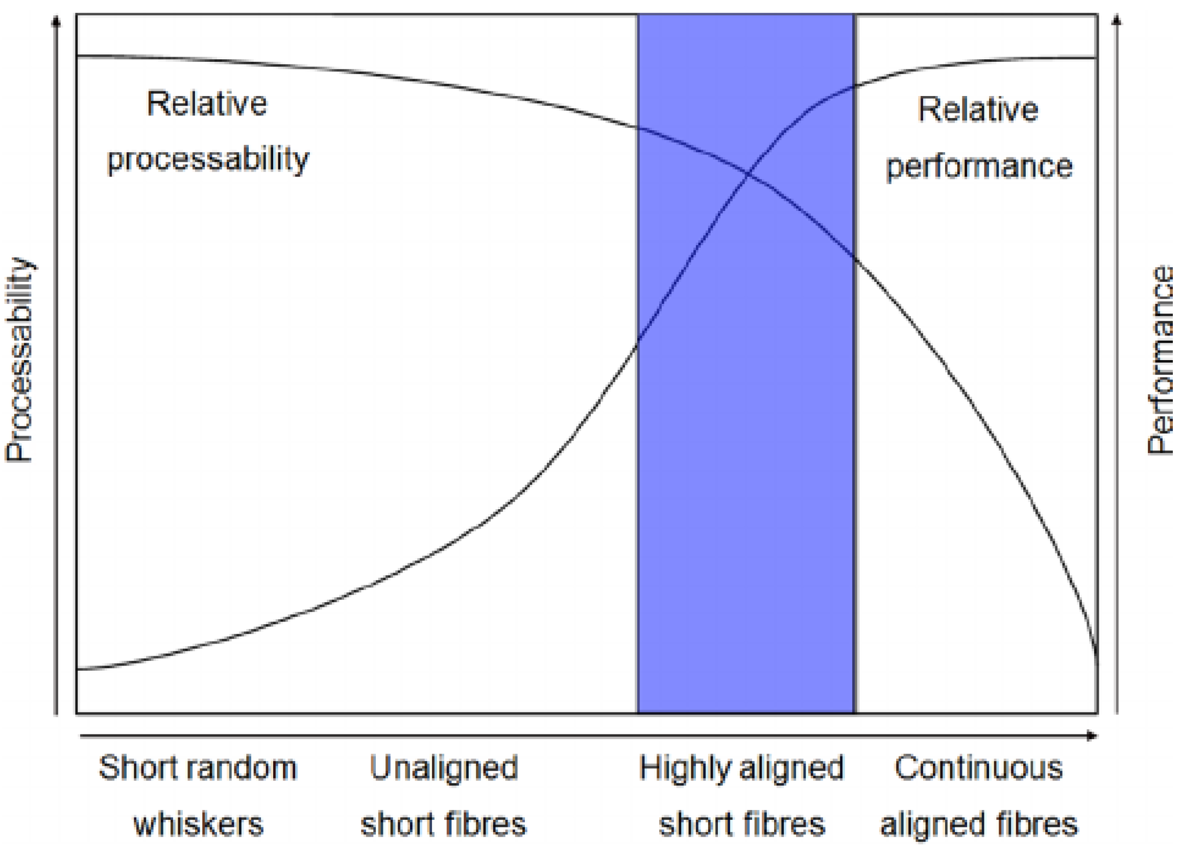
2. Performance of Discontinuous Fibre Systems

There are several parameters at the micro, meso, and macro scales which have an impact on the performance of ADFRCs and these are listed in Figure 3. The microscale represents the level of the constituent materials, the meso scale represents the ply/lamina level, and the macro scale represents the structural response of the laminate.
At the microscale, the reinforcing fibres and matrix play an essential role in shaping the macro-mechanical response of the composite, especially more so for ADFRCs. Fibres with high stiffness and strength properties with little variation are ideal. This is why, reclaimed or natural fibres which have a higher variation in their stiffness and strength properties produce lower composite performance [33,55,56]. If reclaimed fibres are used, the reclamation process must be able to preserve as much as possible the original properties of the fibres. Using fibres with high tensile modulus and strength is important, but the benefit of alignment processes that are currently available is that a combination of different fibre types can be used to produce a material tailored to the design requirements of the customer. For example, with HiPerDiF, fibre hybridisation with other discontinuous fibre types and with continuous fibres has been explored to show its effects on tensile performance, pseudo-ductile response and fracture behaviour [27,29,57]. The mechanical properties of the matrix have less of an effect on the overall performance. However, using a matrix material with high mechanical performance and ductility is necessary to protect the fibres and allow stress transfer as well as provide some (mainly transverse) load. Another thing that will need to be understood further is the quality of impregnation and the interfacial effects between the fibre and matrix, as this also influences the strength of the composite.
The micro parameter, fibre length, has been extensively researched because it has a significant impact on tensile performance. A large fibre aspect ratio allows the fibre to transfer load, minimising fibre/matrix interface failure. The effect of having a large aspect ratio is maximised when homogeneity in the fibre length exists across the composite and, coupled with high alignment, has a direct effect on strength and stiffness properties [1,2]. With perfect alignment and a fibre length 5 times greater than the critical length, 90% of the fibre strength properties can be retained [58]. This has been shown theoretically by Kacir et al. for fibre glass, epoxy discontinuous composites with 6 mm fibres oriented between 0° and 10° [17,59]. With this in mind, it might be logical to use much longer fibres to increase strength, but this poses a risk to the alignment quality, especially with current hydrodynamic methods. Significantly longer fibres increase the amount of flocculation and misalignment because the longer fibres tend to crowd together more. Therefore, there is a balance regarding how much longer than critical length the fibre can be to maintain the benefits of discontinuous fibre composites without reducing performance. This is where computer-based modelling such as flow simulation analysis can be used to understand this balance. This is discussed further later in the paper. The problem is that achieving perfect alignment is very difficult.
At the meso scale, the fibre alignment and areal weight can be improved by optimising the processing parameters of the alignment technique. Composites with highly aligned fibre structures have been shown to exhibit high mechanical properties and a high strain rate capacity [19]. Previous literature has shown that longitudinal modulus can be reduced by about 3% with a misalignment of ±10° [60]. A relationship between alignment and the fracture behaviour of composite has also been demonstrated by Fara et al. and Pavan et al., who observed more fibre breakage in highly aligned short-fibre samples compared to matrix fracture and fibre debonding from samples with low alignment quality [61]. A study by Wong et al. explored the direct effect of the fibre alignment process on fibre concentration and alignment [15]. They concluded that wet hydrodynamic processes are more efficient at highly aligning the fibres, which in turn increases the areal weight of the material. The greater the number of fibres present aligned in the load direction would certainly increase strength and tensile properties [18]. A high alignment of the fibres will also help to reduce defects such as voids or waviness in the laminate. In hydrodynamic processes, nozzle angle, nozzle exit diameter, and fibre concentration can be used to control the flow of the fibre concentrate. As a result, areal weight can be increased and defects such as voids and fibre wrinkling can be minimised [62,63]. New alignment methods on the market such as Tuff [8] and HiPerDiF [64] have produced good results using 3 mm fibres close to but not quite reaching the performance of similar continuous composites.
Damage to the fibres during alignment is another issue which can reduce the mechanical performance of the composite. Ravindran et al. briefly discussed fibre damage in their paper [51], but data from their study and other alignment processes such as TuFF and HiPerDiF are limited. Consequently, little is known about how the state of the fibre varies before and after alignment and how much of an impact damage to the fibres has on performance and quality. The dispersion of the fibres is another key parameter, as it allows a higher volume of fibres to be aligned in the loading direction. Treating the surface of the fibre with a water-based sizing compound has been shown to improve dispersion in water and reduce fluffing [65]. Research by Pozegic et al. has also shown that a surfactant can be added to stabilise the fibre concentration and reduce re-agglomeration [66]. When the fibres are well dispersed with low fibre agglomerations, a high volume of fibres is aligned and the fibre volume content is increased, which can increase mechanical performance. In hybrid composites, having well-dispersed fibres can potentially increase the ultimate strain of the composite by allowing an optimum fibre arrangement at the ply level [26].
The effect of fibre arrangement at the ply level can also be considered when aiming to optimise the performance of ADFRCs. Lei et al. considered groups of unidirectionally dispersed fibres arranged in a regular, stairwise, or random pattern in a ductile matrix as represented in Figure 4 [67]. The fibres and the matrix are considered to display linear elastic behaviour until failure. For regular staggering, the groups of fibres which are modelled as platelets overlap for at least half their length. In the stairwise pattern, the relative positions for each platelet are the same and gaps between them are organised like stairs. The theory is that under tensile load, the discontinuities between the platelets enable them to slide over each other and thus shear the matrix, which allows for a significant proportion of energy and deformations to dissipate prior to failure. According to Lei, stairwise staggering, which is often found in nature [68], achieves higher values for tensile strength and modulus at high aspect ratios compared with random staggering. Pimenta et al. [69] and Czel et al. [25] also investigated similar staggered structures using a brick-and-mortar architecture, as shown in Figure 5. It was found that optimising the size of discontinuities between the platelets can provide a non-linear response before failure with comparable stiffness and as much as 50% of the strength of continuous fibre composites.
Macro-scale modelling normally involves simulating the cured composite under varying loading conditions in order to understand the effects of the micro and meso-parameters. Realistic models must take into account the fibre/matrix interface properties, fibre length, alignment and gaps between fibres which affect the mechanical properties and the failure profile. Other parameters such as fibre volume fraction and composite thickness should also be taken into account. Consideration of the microscale parameters in macro scale modelling to understand tensile performance will invariably make the model more complicated. Manufacturing processes like forming can also benefit from this technique in order to effectively understand the optimum conditions for improved performance or to reduce the formation of defects like voids and wrinkling. In this way, the high formability of discontinuous fibres can be utilised effectively and simulation used in an effort to reduce manufacturing defects. More detail is provided in Section 4, where the latest development in the area of predicting the forming capabilities of ADFRCs is explored. The development of modelling tools will help to understand how to control the behaviour of the material, the process parameters and the thermally induced residual stresses during the forming stages to ensure a high performance of the final composite.
To conclude, several points along the re-manufacturing process can be modelled, but it is important to remember the inherent limitations in the modelling techniques employed to approximate the real-world situation. The information that goes into a model is always idealised, and it is not possible to account for every variation; the accuracy of the modelled result will depend on how well the inputs reflect reality. This is especially true for modelling discontinuous fibres, as their variations far exceed that of their continuous counterparts. Early models consisted of fibres with uniform length, perfect alignment, consistent mechanical properties, and failure profile. These early models were only sufficient in predicting trends for tensile modulus and strength of discontinuous fibre composites. Only recently have variations within the fibres and the matrix behaviour and laminate properties been considered [70]. However, as will be explored later, they do not adequately consider all fibre–fibre or fibre–matrix interactions and behaviour to make sufficiently accurate predictions. Simulation of the forming process of ADFRCs is also new, as previous models concentrated on short fibres (not aligned) in flow-based processes. Another point to consider is that these models were not evaluated with experimental data from highly aligned fibre-reinforced composites due to the capabilities of early fibre alignment techniques.

3. Performance Modelling of Discontinuous Fibre Systems

Several of the models used to predict the performance of discontinuous fibres were originally adapted from their use with continuous fibre composites. However, the focus has been mostly on short-fibre composites with fibre lengths less than 1 mm, which do not require a high level of alignment. Now that high alignment techniques have been developed and commercialised, the industry can fully utilise the potential of discontinuous fibre systems. In the previous chapter, the parameters required to fully define and assess the performance of ADFRCs were discussed in depth. It was important to understand how performance is affected by these parameters, which are all the microscale characteristics that would feed into any theoretical model to adequately represent ADFRCs. Additionally, modelling techniques can now further evolve as more accurate experimental data can be made available.
This section will review the evolution of analytical, numerical, and process modelling techniques and how and why they can now be re-purposed to analyse highly aligned discontinuous fibre composites (ADFRC). Figure 6 provides an overview of the common models and theories that have been used in the literature to analyse the performance of discontinuous fibre composites, aligned and random.

3.1. Analytical Modelling

Traditionally, micromechanical models have been used to analytically predict the properties of discontinuous fibre composites. Analytical models are more common because they are simple, low cost, and can quickly give a general trend of the performance of the composite. They are usually divided into two groups, models based on the theory of elasticity such as the Self consistent model [71], Lielens model [72], the Mori-Tanaka method [73], and the rule of mixtures (ROM)-based models like the modified Halpin Tsai [74], and the modified ROM [75]. A comprehensive review of how micromechanical models are used in predicting elastic properties is provided by Tucker et al. [72] and more recently by Vignoli et al. [76]. One of the more successful models the shear lag theory was adapted from the simple rule of mixtures (ROM) equation which has been used to predict the tensile modulus for continuous fibre composites.
E c = V f E f + V m E m
where E is Young’s modulus, V is the volume fraction, and the subscripts c, f, and m denote composite, fibre, and matrix, respectively, and while the ROM equations are perfectly reasonable for continuous fibres, they suffer drawbacks when applied to discontinuous fibres. Yu et al. gives an indication of this in their investigation of the tensile behaviour of hybrid ADFRCs [24]. In Figure 7, Yu et al. illustrate that the experimental results of the tensile modulus of intermingled hybrid ADFRCs fall somewhere between the predictions of the parallel and series rule of mixtures [24].
Cox’s shear lag theory was one of the first micromechanical models to modify the ROM equation to be used for discontinuous fibres. The shear lag theory considered the behaviour of a single fibre greater than its critical length, embedded in a matrix and undergoing elastic deformation. Cox assumed that stress transfer only happened along the fibre length and not at the ends. Therefore, an increase in the fibre length caused the tensile modulus to increase significantly. According to Cox [77], a reduction factor is required because the fibre lengths do not fully contribute to the composite’s modulus. Krenchel’s theory was used by Houshyar et al. [78] to expand Cox’s theory by adding a reduction factor to account for the effect of orientation of the fibre. As a result, the ROM equation was modified [3,79,80] to give
E c = η o η 1 V f E f + V m E m
where η o represents the fibre alignment factor and η 1 the fibre length factor.
To estimate η o , the composite is broken up into sections according to the alignment angle of the fibres, which is a similar approach to that of classical laminate theory [81,82]. The modulus ( E θ ) of each section aligned at an angle θ can be calculated using Equation (3) [83].
1 E θ = c o s 4 θ E 1 + ( 1 G 12 2 ν 12 E 1 ) s i n 2 θ c o s 2 θ + s i n 4 θ E 2
where E 1 is Young’s modulus in the fibre direction, E 2 is Young’s modulus normal to the fibre direction, G 12 is the shear modulus, and ν 12 is Poisson’s ratio. Young’s modulus of the composite ( E c ) is then calculated as a sum of each section using Equation (4) [75,83].
E c = k = 1 n E θ k t k
where E θ k is the modulus of each section oriented at each angle θ and t k is the percentage of fibres aligned at each corresponding angle θ . η o can then be calculated using Equation (5) [77,83].
η o = E c E θ
where E θ is estimated as the modulus of the composite when all the fibres are aligned perfectly.
Cox’s shear lag theory is used to estimate η 1 , the fibre length factor using Equation (6) [77,83].
η 1 = 1 t a n h ( a l / d ) a l / d
where l and d are the length and diameter of the fibre and a can be calculated from Equation (7):
a = 3 E m 2 E f l n V f
In a similar approach based on the Kelly–Tyson slip theory [84], a reduction factor for the effect of fibre length on strength is added to give the following [75,83,85]:
σ c = η 2 η 3 V f σ f + V m σ m
where σ is the ultimate tensile strength of the composite (c), fibre (f), and matrix (m). In this case, η 2 and η 3 are considered the fibre direction factor and the fibre length factor, respectively. η 2 is estimated in the same manner [83] as was η o by first using Equation (9), as follows:
1 σ θ 2 = c o s 4 θ σ 1 2 + ( 1 τ 12 2 1 σ 1 2 ) c o s 2 θ s i n 2 θ + s i n 4 θ σ 2
where τ represents the shear strength of the composite, σ 1 2 the tensile strength of the composite in the fibre direction, and σ 2 the tensile strength normal to the fibres. η 2 is then calculated using Equations (10) and (11) [83];
σ c = k = 1 n σ θ k t k
η 2 = σ c σ θ
σ θ is estimated as the tensile strength of the composite when all the fibres are aligned perfectly. η 3 is estimated using Equation (12), as follows:
η 3 = 1 S c 2 S
where S is the fibre aspect ratio (length/diameter).
Finally, S c , the critical fibre aspect ratio, is calculated [86] using Equation (13):
S c = σ f τ i
where τ i is the interfacial shear bond strength between the fibre and the matrix.
The main drawback with the original shear lag model is that it did not consider the variations that exist within the constituent properties (i.e., the fibres and matrix were considered to be linearly elastic, with all fibres identical in shape and size and experiencing perfect bonding at the interface). Nor were the stress transfer between the fibres and the matrix and the interactions at the fibre ends taken into account. The focus was mainly on ADFRCs composed of short fibres (less than 1 mm long) [2,87]. This meant that the interface that has more control over the mechanical properties at longer lengths was not considered. In addition, the effect of the length distribution on the mechanical properties was not considered. Therefore, these early works reported varying success in predicting the mechanical properties of ADFRCs. The failure profiles predicted were also much different from what we now see with longer fibres. However, subsequent works [1,73,88] started to look at the effects of the distance between the fibre ends. It was found that these discontinuities caused a high stress concentration on the adjacent unbroken fibre, which could lead to failure of the ply when the gap was maximal. Thus, it became increasingly evident that this behaviour should be considered when predicting the behaviour of discontinuous fibre composites.
Hikami and Chou also considered the effects of matrix stress transfer behaviours on strength [89]. In composites with elastically deforming matrices, the strength was significantly reduced, whereas with plastically deforming matrices, there was good agreement with predictions from Kelly and Tyson’s modified ROM. This was attributed to the plastic deformation of the matrix, which was thought to reduce the local stress concentrations at the fibre ends. Sanadi et al. [83] investigated the effects of fibre length, volume fraction, and surface condition on the strength and stiffness of aligned fibre composites with 1 mm to 5 mm long fibres. They showed the importance of accounting for the stress transfer behaviour of the fibres next to the fibre ends to achieve realistic prediction. Sanadi et al. found that applying shear lag theory to simulate the changes in modulus with fibre length was not in good agreement with experimental data, but this could have been due to the manufacturing method causing fibre breakage and yielding composites with shorter fibres than expected.
Hsueh et al. modified the shear lag theory by adding imaginary fibres to the bonded ends in order to achieve a more rigorous boundary condition [90,91]. By reducing the ambiguity at the fibre ends, they were able to demonstrate good agreement with simulations made which used the finite difference method for the distribution of normalised interfacial shear stress (previously underestimated) and axial stress (previously overestimated) [90]. Consequently, Hsueh et al. went on to extend the modified shear lag model to include a representative volume element (RVE), which was more suitable for analysing short fibres [91]. The purpose of this study was to improve the predictions of Young’s modulus, and this was achieved. The stress transfer and the modified shear lag model by Hsueh et al. was in good agreement with other theoretical solutions: the Halpin–Tsai equations, Eshelby model, and finite element analysis [91]. Predictions of Young’s modulus were also compared with experimental results, but these were obtained with less-aligned particulate-reinforced composites, and thus the model by Hsueh et al. could usefully be validated in the future using more current experimental data.
Further studies have looked at how the properties of the fibres affect the strength of the composite [1,2,73,85,88] and Fu et al. showed that as the mean fibre length increases, the percentage of fibres less than the critical length decreases and reaches a plateau around 5 times greater than the critical length. Thus, applying this trend to the strength equation derived by Fu et al. means the tensile strength also increases with mean fibre length [85]. Thomason et al. also looked at the effect of fibre concentration on glass-fibre-reinforced polypropylene fabricated using a wet deposition re-manufacturing process. They reported linear increases in both strength and modulus with the fibre concentration up by 40% [88], whereafter the tensile performance started to taper off but still achieved increases of up to 25%. The researchers concluded that this could be because of issues with fibre packing causing voids and misalignment. Without experimental data, this theory could not be validated, but does invite a discussion of the effects of controlling fibre dispersion during the processing of the fibres. If the fibres are not well dispersed, then the number of voids present in the preform increases, and this leads to a reduction in the final mechanical properties. Cox’s original shear lag model has been further developed over the years to take into account some of the behaviour and variability of discontinuous fibre composites. The modified shear lag models have shown promising results in predicting performance, but they do not present a realistic picture as they are not validated using data from highly aligned fibre composites and did not take into account the variability in the fibre and matrix or defects like wrinkling or voids. A summary of the development of the shear lag theory is shown in Table 2.
Visweswaraiah et al. [94] reviewed the suitability of other analytical models for discontinuous fibre composites. They identified that while common analytical models like those of Kelly–Tyson, Mori–Tanaka, and Lielens were adequate for predicting strength and stiffness, they were too simplistic and did not effectively consider the effect of process and geometrical parameters on the behaviour of ADFRC. In addition, these theories were also not validated extensively with experimental results due to the lack of data for ADFRCs.

3.2. Numerical Modelling

Analytical micromechanical approaches have been used to predict the elastic properties of discontinuous fibre composites with reasonably good accuracy, but capturing the local stress field of realistic microstructures as well as the corresponding progressive damage is beyond their capability [95]. On the other hand, numerical models (summarised in Table 3) have been used to model more complex structures. Using numerical modelling techniques, the actual size can be modelled to achieve a deeper understanding of the microstructure of the composite. An additional advantage of numerical models is that once validated, they can be easily extended to larger component sizes. FE-based numerical models have been popular for predicting the behaviour of discontinuous fibre composites, but their accuracy depends on the accuracy of the internal architecture of the structure that is being modelled. In FE-based models, it is complicated and time-consuming to generate a finite element mesh for complex 3-dimensional structures. Therefore, an RVE is developed to represent the composite. Babu et al. [96] used an RVE representation of short-fibre composite material at the microscale and implemented geometric periodicity to ensure the continuity of the fibres across the neighbouring RVEs. The effective stiffness of in-plane aligned short fibres was predicted using the mathematical theory of homogenisation, and the results were found to have a good correlation to analytical or non-RVE methods like the Mori–Tanaka and the Halpin–Tsai methods. A successfully generated RVE is small enough to be modelled effectively, but large enough to represent the physical microstructure and geometrical parameters of the composite. In this way, the mechanical response provided by the RVE during analysis represents the mechanical response of the entire composite without the large computational time. Three widely used methodologies to generate RVEs are the Monte Carlo method [97,98,99,100], the image reconstruction technique [101,102], and the random sequential absorption schemes [96,103,104,105,106,107]. A depiction of an RVE and the generated mesh is shown in Figure 8 based on the random sequential adsorption technique for in-plane aligned fibres. A detailed review of RVE generation methods can be found in [108]. The RVE of the heterogeneous microstructures of discontinuous composites is established considering the fibre length distribution, the fibre volume fraction, and fibre orientation distribution. FE-based modelling approaches do have limitations. In traditional models, the macroscopic structure and the composition of the composite were considered uniform throughout. In addition, a simplified geometry for the fibre strands was used to reduce computational time and provide conclusive results. Modelling a more accurate geometry of the fibres was found to be computationally expensive because of the variability within the fibre structure and the stochastic nature of the fibres [47]. The size of the RVE is fixed, and therefore increasing the aspect ratio of the fibres is challenging because of the risk of inclusion, overlap, and interaction between the fibres. Therefore, most FE-based models employed simple structures of regularly spaced fibres, with low fibre volume fraction, low aspect ratio, and a low number of fibres [96]. Even in newer RVE generation techniques where the aspect ratio can be increased, assumptions are made about the alignment and fibre length distribution and a coarser mesh is required [101]. This is done so that computational performance can be maintained. Thus, with RVE generation methods, performance and damage analysis of ADFRCs is not completely representative.
Velmurugan et al. [109] investigated the influence of fibre waviness in discontinuous fibre composites using sinusoidal-shaped curved fibres in an FE-based computational micromechanics approach and found that fibre waviness had a significant influence on the longitudinal elastic properties. Koley et al. [110] developed RVEs for unidirectional fibre-reinforced composite material reconstructed from image processing techniques to generate statistically equivalent fibre distribution which is similar to the real scenario. A good comparison of the in-plane mechanical properties with respect to experimental data was achieved by the homogenisation method of the RVEs considering the random distribution of the fibres and different fibre cross-sections. Cai et al. [111] used micro-CT images to develop a simplified microscopic model reconstructed using the 3D parametric finite-volume direct averaging micromechanics (FVDAM) theory. Visweswaraiah et al. [94] conducted a more recent review of micro, meso, and global–local models used to analyse randomly oriented fibre and strand composites. According to Visweswaraiah et al., choosing the correct RVE size can be challenging and this is confirmed by the numerous studies that have been performed to determine the correct RVE size required for modelling [98,105,106]. The Tian method has been used to spatially model randomly distributed discontinuous fibres with relatively high fibre volume fraction [112] and Pan et al. later proposed a methodology for generating RVEs that can achieve higher volume fractions (i.e., 35.1%) by using curved fibres [103].
The generalised method of cells (GMC) is a more computationally efficient alternative to direct numerical simulations for the determination of effective elastic properties of composites. The basic ideas of these approaches involve subdividing the unit cell into numerous cuboid subcells, solving for the average strain and stress over each subcell, and obtaining an estimation of the local fields. Pahr et al. evaluated the predictive ability of the GMC in the context of ADFRCs and compared it with micromechanically based mean field models and FE unit cell models [113]. They found that while the GMC was fully capable of accurately analysing the elastic behaviour, it had some shortcomings when modelling the longitudinal elastoplastic behaviour due to the inherent lack of normal-shear coupling. A modified GMC with an artificial bilinear matrix material definition within the subcell was shown to yield improved predictions in the elastoplastic regime [113].
Sertse et al. [114] evaluated the predictive capability and efficiency of advanced micromechanics approaches which included GMC, the high fidelity generalised method of cells (HFGMC), and the variational asymptotic method for unit cell homogenisation (VAMUCH) and Finite Element Analysis (FEA)-based micromechanics approaches for aligned discontinuous fibres in regular array and staggered array arrangement. Sertse and Yu [115] also evaluated the capability of these models to predict the static failure strength and the initial failure envelope of ADFRCs and found that VAMUCH produces the initial failure envelope for axial and transverse shear loading using both maximum shear stress and Tsai–Hill failure criteria. Bouhala et al. extended the VAMUCH method by applying the eXtended Finite Element Method (XFEM) directly onto nonconforming meshes of RVEs produced by microstructure generator [116]. Sertse et al. [117] also compared the predictive capability of micromechanical modelling tools such as DIGIMAT-MF, ESI VPS, MAC/GMC, finite volume direct averaging method, Altair MDS, SwiftComp, and 3D finite element analysis and presented the results from benchmark cases. Mirkhalaf et al. [118] demonstrated that a micromechanics-based approach, combining FE and Orientation Averaging, can be used to predict elastic properties of short-fibre-reinforced composites. A self-consistent interaction between the upper and lower bounds was developed, and it was shown that this intermediate approach was applicable to almost any short-fibre composite with an arbitrary fibre volume fraction, fibre aspect ratio, and fibre orientation distribution.
The boundary element method (BEM) is another numerical approach which has been used to model fibre composites [119,120,121]. BEM offers greater flexibility in its models than FE and other numerical models. This flexibility, when modelling more complex structures, arises because only the boundaries of the model need discretisation, thus simplifying the FE mesh generation, reducing the computational time and making it more efficient. Fully 3-dimensional models with up to 200 rod-like fibres can be generated quickly. A visual representation of a BEM model is shown in Figure 9a. Several studies have used BEM to predict the longitudinal modulus of discontinuous fibre composites [119,120,121,122] by modelling the ply layers with rod-like fibres and assuming the fibre and matrix to be linear elastic and uniform. The axes of the fibres are used to define their orientation, whether random or aligned. Both Ingber et al. [120] and Gun et al. [121] compared their predictions to theoretical analysis, although Ingber et al. validated their results with predictions from Halpin–Tsai and Nielsen, which showed some agreement but only when both fibre aspect ratios and fibre volume fractions were low. It has already been shown that the Halpin–Tsai model gives a wide range of moduli for discontinuous fibre composites, making it less accurate when compared to Cox’s theory. Furthermore, the BEM model reported by Gun et al. did not correlate well with the Kelly–Tyson and the modified Cox models, which can generally give a good indication of trend for mechanical properties. In contrast, when Papathanasiou et al. compared their results to experimental data generated from samples with fibres aligned using a hydrodynamic elongation flow method [119], they found good agreement with experimental data and demonstrated that aligned fibres were 90% more effective in improving tensile properties when compared with random fibres [119], and while this indicates the positive effect on stiffness from increasing the volume fraction, the authors studied only low-volume fractions (<20%) and short fibre lengths (0.0015 cm to 0.3 cm) with no indication of the alignment distribution. The results of Papathanasiou et al. suggest that both the processing technique and the fibre–fibre interactions play roles in the magnitude of the mechanical properties produced, but this was not investigated further. In conclusion, the BEM model offers a viable alternative for prediction, but it usually utilises a volume fraction of less than 20% with a small number of fibres, typically 200 or fewer. The scatter in the modelled data of Ingber et al. increases with the number of fibres to give a more accurate representation [120]. These constraints limit BEM modelling techniques to short discontinuous fibre composites typically processed using injection or compression moulding and potentially render it unsuitable for highly aligned composites with volume fractions higher than 50%.
The peridynamic (PD) technique considers the macro-scale [123,124,125] and the composite specimens modelled as ply layers, within the specimen during various loading conditions (predominantly in tension). In PD, a heterogeneous particle model is used (Figure 9b), where all the particles have the same volume and the bonds between the particles are used to represent the fibre orientation. This method has been mainly used to look at damage progression in the composite panel during tensile loading. The drawback with this method is that it does not represent the full thickness or size of the specimen; all particles that are modelled having the same volume and variation in fibre length or in the matrix properties are not considered.In addition, it does not take into account the effects of defects such as wrinkling and voids. Consequently, predicted results do not always agree with the behaviour of the actual composite. Any change to the geometry of the model has been shown to increase the scatter of the tensile results [125]. Zhang et al. found that the smaller model better predicted the tensile modulus, whereas the larger model was closer to actual experimental results for tensile strength. This shows the inconsistency of modelling discontinuous fibre composites in this way [125]. The model reported by Qu et al. went further by investigating the effects of interfacial properties on the mechanical response of the composite [124]. They used the PD theory to show that a composite with a weak interface exhibits fibre debonding in contrast with fibre breakage seen with a strong interface during tensile loading. Similar to BEM, predictions using these techniques will not accurately describe the behaviour of ADFRCs without significant work being undertaken to define the fibre geometry and interactions. In addition, if defects in the fibre or variation in the fibre properties are considered, the running time would significantly increase, making these methods more complex. As a result, neither of these modelling techniques have been used for highly aligned discontinuous fibre composites.
Other modelling techniques like the layer-wise method (LWS) [126], periodic unit cell simulation (PUC) [127], and the spring element method (SEM) [128] have also been used to predict tensile strength by analysing the failure modes present. In the layer-wise method, the viscoplastic response of the matrix has been included to assess more accurately the effect fibre length has on tensile strength and fracture mode of partly aligned discontinuous thermoplastic composites. Nishikawa et al. [127] used the PUC model to investigate the effect of fibre length on the damage modes present during fracture and the final strength of the composite. The stress concentration and the distance between fibre ends were considered when predicting the critical fibre length. Okabe et al. [128] used a 3D SEM model to predict the strength of a real-size specimen with four fibre lengths ranging from 0.3 to 4 mm. The failure modes observed using this technique changed from a significant number of broken fibres to few or no fibre breakages as the fibre length decreased. However, when compared with experimental results for randomly oriented thermoplastics, this method tended to exaggerate predicted strength values, could only simulate damage modes independently, and could not be used to consider combinations of fibre breaking and debonding simultaneously.
To summarise this section, the main numerical models that have the capability of predicting the behaviour and performance of ADFRCs along with their considerations and limitations are detailed in Table 3.
Table 3. Summary of the main numerical models used to predict properties of discontinuous fibre composites.
Numerical ModelParameterDescriptionLimitationsExperimental Validation
boundary element metho
(1995–1997)
[119,120,121,122]
StiffnessFlexibleLow volume fractionHydrodynamic alignment [121]
Simple mesh generationUse of shorter fibres
Low alignment
Periodic unit cell
simulation
(2009)
[127]
StrengthAnalyses failure modesHigh computational cost-
Includes stress concentration at fibre endsDifficulty scaling up specimen size
Includes fibre end gapShorter fibre lengths
Considers matrix stresses and fibre breaking
FE-based models
(2011–2020)
[47,109,111,116]
StiffnessRVE analysisLow fibre volume fraction-
Ability to scale up specimen sizeSimplified geometry
Low number of fibres
Layer wise
(2012) [126]
StrengthAnalyses failure modesVariation in fibre length and orientation not consideredRandom thermoplastic press moulded composites [126]
Uniform fibre angle
Includes viscoelastic response of matrix Data
Data Considers fibre failure
Spring element
(2014)
[128]
StrengthAnalyses failure modesVariation in fibre orientation not consideredRandom thermoplastic press moulded composites [126]
Damage progression3D SEM suitable only for longer fibresUnable to combine failure modes (only includes fibre breaks)
Considers fibre length variations
Peridynamic technique
(2018–2021)
[124,125]
StrengthParticulate
macro scale model
Difficulty scaling up specimen size
Variation in fibre length
-
Damage progression not considered
Wrinkling or voids not considered
Inconsistency in modelling
Mainly for damage progression

3.3. Recent Works on Modelling Predictions Using ADFRCs

As discussed earlier, there is a clear indication that the consideration of fibre and matrix variations is important to determine a realistic prediction of mechanical performance. As a result, more recent analytical models began to include the effects of the stochastic nature of the fibre and matrix variations on mechanical response, deformation, and failure behaviour. Pimenta et al. developed a multiscale model using a modified shear lag theory and the Dugdale strip failure criterion to investigate the tensile response of ADFRCs [129]. Shear-lag theory was used to define the interactions between each fibre and each segment of fibres. The composite was modelled as a series of representative volume elements (RVEs) with each RVE section modelled as a number of fibres at the desired fibre length. Results from the model showed that the mechanical response of an ADFRC was dependent on the type of matrix, and this effect was more pronounced for ADFRCs with shorter fibre lengths, as shown in Figure 10. Pimenta et al. found that although the pseudo ductile response of the composite increased as fibre lengths decreased, there was still a minimum fibre length threshold (approximately 0.8 mm), where below which the strength would be reduced drastically [129]. At longer lengths, this effect was somewhat minimised, and the stress–strain response is shown to be nearly linear. Pimenta et al. also confirmed the effect of fibre length on the strength and stiffness properties up to a plateau level which coincides with a fibre length of around 3 mm.
Using similar principles, Henry et al. modelled full-size 3D ADFRCs and considered random interaction at the fibre ends, the variation in fibre strengths, and behaviours at the fibre/matrix interface. The behaviour of the composite was investigated at final failure and a variety of damage types was observed, like matrix debonding [130]. For shorter fibre lengths, failure was dependent on the overlap length, whilst for longer fibres it was dependent on the fibre strength. Using this model, Henry et al. were also able to show good agreement with experimental results obtained using the second-generation HiPerDiF machine (HiPerDiF 2G) [7,31]. The model predictions also agreed with the earlier simulations from Pimenta et al. on the effects of fibre length on stiffness, strength, and failure (Figure 8). Henry et al. were able to predict that 3 mm-long fibres give a more linear stress–strain response that is similar to that of continuous fibre composites for brittle and ductile matrices [130].
Other researchers [26,131] have used multi-scaled models to investigate the effect of hybridisation on mechanical properties and behaviours like pseudo-ductility. It was found that the effect of hybridisation was more apparent when there was a large difference in modulus between the different fibre types or better intermingling between fibres. A virtual testing framework (VTF) based on Cox’s shear lag theory has also been developed to capture the effects of variability and defects on strength, stiffness, and ductility [70,132]. Predictions using the VTF showed that the fibre strength, the distance between fibre ends, levels of fibre intermingling, and void content had the most critical effects on modulus. This work also suggested that voids can be reduced by hybridisation, although this has yet to be proven experimentally.
Using a multi-scaled FE-modelling approach, Wang et al. took into account fibre misalignment, distance between the fibres, the effects of fibre-matrix debonding, and local variations in fibre volume fraction locally [133]. This approach considered the stochastic nature of ADFRC and defects like fibre misalignment, as well as variations in inter-fibre gaps and fibre volume fraction. In this way, it is possible to understand the different failure modes present and their relationship to the behaviour of the composite across each scale. In Figure 11, Wang et al. show that although the initial slope of the curve for both the discontinuous and continuous fibre model is similar to that of the rule of mixture estimate, there is a 25% reduction in strength for the discontinuous fibre models when the fibres were misaligned by 15° [133]. Wang et al. attribute this to the quality of the bonding between the fibre and matrix and the occurrence of stress concentration at the fibre end gaps.
Another recent work by Li et al. reported a computational framework which incorporates fibre length and alignment distribution, non-uniformity of stresses around the fibre, and damage evolution [95]. The modelling framework can be applied to thermoset and thermoplastic matrices reinforced with different types of fibres under a variety of loading conditions. Damage initiation and propagation were simulated in the model and compared favourably with in situ experimental data from tensile tests performed on short-fibre glass thermoplastic composites. The model shows good agreement with the experimental results. In addition, tensile strength and stress data compared well with the orientation average method and modified ROM [95], although the focus was mainly on short-fibre composites (≤1 mm) at low volume fraction (≤0.3%). Therefore, the model by Lei et al. would need to be expanded to simulate the behaviour of ADFRCs using longer fibre lengths.

4. Process Modelling of ADFRC

There are three key stages in the manufacturing process of ADFRC composites that could benefit from modelling.
  • The alignment stage—to understand how the fibres behave in a fluid in order to optimise the alignment quality.
  • The forming stage—to predict the behaviour of the matrix and fibres during tape placement, as well as understand defect formation.
  • The curing stage—to understand how the matrix and fibres behave when heat is applied.
The importance of process modelling is that it can be used to understand how the material is influenced by the material, environmental, and mechanical parameters. It can also be used to optimise performance and control defect formation. Previously, a significant portion of research went into optimising the performance of manufacturing processes like injection moulding [134], compression moulding [135], or extrusion [80]. In the case of ADFRCs, process modelling is still in its infancy, but because of their superior formability and improved performance, understanding their behaviour is important to appeal to a wide range of industries. There has been some published work on the modelling of fibre alignment and composite forming, and this will be summarised in this section. Modelling techniques that have been used to simulate the behaviour of ADFRCs during the curing stage will not be discussed in this review.

4.1. Fibre Alignment Modelling

Some research has been conducted on the effects of various process and machine parameters during the alignment stage using various computational fluid dynamics methods [136,137,138]. Parameters like nozzle dimensions, flow rate, viscosity of the suspension liquid, and fibre lengths have all been found to influence the alignment quality, although these studies have focused primarily on the alignment of fibres in viscoelastic fluids during processes like injection moulding [137,139,140]. Injection moulding typically uses fibres that are ≤1 mm in length and are aligned directly into a formed part, but this is quite different from the hydrodynamic alignment techniques we wish to understand.
Recently, Huntley et al. used a smooth particle hydrodynamics model (SPH) to model the alignment of fibres in the HiPerDiF process [141]. SPH is a fully Lagrangian mesh-free particle method developed originally for astrophysics problems but now used to model fluid systems. The authors were able to successfully simulate the effect on alignment when selected process parameters in the HiPerDiF equipment, like the alignment head plate spacing (Figure 12) and the nozzle angle (Figure 13), were varied.
Huntley et al. predicted, using the SPH model, that a plate spacing of 0.3 mm would ensure over 75% of the fibres were aligned in the loading direction as shown in Figure 12. Interestingly, for longer fibres (7.5 mm and above) the SPH simulation demonstrated that alignment quality dropped to below 80%. This was attributed to stacking issues with the fibres during the alignment phase; however, this was not validated. The SPH model was also used to investigate the effects of fibre length on alignment quality [141], and the simulation predicted that a shallow nozzle angle of between 0° and 30° and a fibre length between 4 mm and 6 mm would produce an alignment quality of greater than 80% with the fibres aligned within ±3°. This modelling work is a good start and has the potential to assist the development of hydrodynamic processes like HiPerDiF or AFFT [7].

4.2. Towards Forming Predictive Capabilities

To date, there have been limited efforts for process modelling and manufacturing complex parts made of ADFRCs. This is primarily because ADFRCs are relatively new in both the research field and the commercial market. Nevertheless, studies conducted on short-fibre composites and the forming of textile composites can offer valuable insights to help predict the manufacturing processes for ADFRCs. Simulation studies of short-fibre composites forming started with flow-based methods, which are very well developed [142,143,144,145]. These studies are based on the fibre orientation changes during the flow of the matrix during infusion manufacturing. Assuming that the matrix is an incompressible Newtonian liquid, the stress created by the pressure difference causes deformations. The extension of material created by the flow in these deformations helps the fibres to align in the direction of the extension, as seen in Figure 14 [145]. The same phenomenon happens during a tensile test of the ± θ laminate where the fibres align along the loading direction, but the volume fraction in these studies is below 1%.
Flow-based simulations are also used for sheet moulding compound (SMC) composites by considering material flow inside the mould other than shape change with draping [146], while the matrix does not flow during the forming of woven composites and matrix flow is unwanted for unidirectional and aligned short-fibre composites, as it would disturb the designed fibre alignment. Nevertheless, a simulation of matrix flow may be needed to estimate the thickness/width change of a layer under compression stress due to high pressure applied by the mould [147]. Therefore, the flow-based simulations could be counted as a starting point, but it would be unnecessary to implement it into forming modelling if there is no flow of the material. Compared to the short fibre infusion and SMC, current developments within draping simulations of continuous fibre composites could offer better basis for simulating the forming of ADFRCs. Like flow simulations, forming models for continuous composite have been studied for the last decade to reach defect-free complex shapes [54,64,148,149,150,151,152,153,154,155]. Fibrous materials made of dry or impregnated textiles have two main features during the forming process: shear locking, where tracking the fibre direction (warp and weft) is needed, and decoupling of tensile and bending properties. The latter is necessary as the matrix does not transfer load for uncured thermoset continuous fibre prepreg and thermoplastic continuous fibre at forming temperatures, or there is no matrix to transfer load for dry fabrics [54,147,153].
Most of the methods using 2D elements in the literature try to implement the decoupling effect of bending and tensile behaviour of materials differently. The first option is using shell and membrane elements together to imitate the decoupling of material properties [54,149], while in-plane tensile behaviour is covered using membrane elements, and shell elements that make it possible to represent the fibrous material behaviour in bending. Another option is to use membrane and truss/beam elements together with the same logic, where the beam elements provide bending properties [148,150,151,152]. Other authors have also proposed the use of only shell elements with a laminated layup like a sandwich structure with a core to decouple tensile and bending stiffness [64,154,155]. In all these cases, non-linear material behaviour for shear behaviour [54] and non-linear material behaviour for bending [64,154,155] are also implemented to reach better results. One of these models can be adapted to simulate ADFRCs. Additionally, interactions between layers like friction, adhesion and separation also need to be considered during forming simulations because unrealistic gaps and relative movements of layers can lead to significant differences between experimental data and simulations of the fibre direction, defect areas (wrinkles) and the location of a layer [54,153].
As discussed earlier, input properties are important for each method mentioned above and can be divided into pure modes [156], that can be assumed or improved analytically through methods originally developed to capture the behaviour of a matrix filled with aligned short fibres [144]. In 2D simulations, tensile and bending modes in the fibre direction (decoupling effect), the tensile mode in the transverse fibre direction, and the in-plane shear mode form four pure modes. A fifth mode, the thickness change under a compression load in the transverse direction, can also be added to the aforementioned simulations. The viscoelasticity of the matrix, which varies with temperature, degree of cure (for thermosets) or crystallinity (for thermoplastics), and fibre length are the main material properties needed to calculate these behaviours [157,158,159]. These analytical models may decrease the number of tests needed for simulations. However, they are generally not close enough to use directly due to impurities and heterogeneities in the material, such as voids, misalignments, changes in volume fraction, and simplifications of microstructures. Although the tensile and bending behaviour vary less when measured for ADFRCs, it is still necessary to verify the data.
A cantilever bending test method can also be used to determine the bending behaviour of ADFRCs [64,151]. On the other hand, because there is no decoupling effect for the transverse direction, the tensile behaviour also covers the bending behaviour. Moreover, the shear properties are also necessary to simulate ADFRCs successfully [160]. If the forming method is neither isothermal nor quick, then the nature of the matrix material will need to be considered; the two main possibilities are thermoset and thermoplastic polymers because all the properties depend on the load transfer of the matrix. Thus, the level of the cure for thermosets and the process temperature for both thermoset and thermoplastic will affect properties and add another variable to the forming simulations. This is confirmed by the simulation by Guzman-Maldonado et al. (Figure 15) of the temperature change observed during thermoforming of a thermoplastic prepreg [161]. Therefore, temperature or curing-dependent mechanical properties must also be included in the modelling if the property change is high during forming [161,162].
Preliminary data illustrating how the proposed framework could work have been collected by Yavuz et al. [163,164], who characterised the tensile behaviour of carbon fibre tapes produced from reclaimed carbon fibres (using HiPerDiF) with poly(L-lactic acid) (PLA) under various processing conditions (i.e., temperatures between the glass transition temperature and melting temperature of PLA) [163]. In an attempt to model the observed behaviour, the tensile load-carrying capacity of the material was hypothesised to be largely dependent on the ability of the matrix to withhold load under shear loading, as illustrated in Figure 16 [164].
Matrix shear properties were obtained by rheological experiments performed at different temperatures, levels of crystallinity, and shear rates. Shear stress in the system was assumed to follow a Maxwell model (see Equation (14)). In Equation (14), G is the storage modulus and η is the viscosity [165]. The correspondence between the tensile stress in the HiPerDiF tape and the shearing of the matrix in the inter-fibre channels is given in Equation (15), where D is fibre diameter, f is fibre volume fraction, and δ is fibre overlap length [144].
η γ ˙ = τ + η G τ ˙
σ = 2 τ f δ D
This micromechanical model was implemented into a user material subroutine for the Finite Element package Abaqus/Explicit. As illustrated in Figure 17, a good match between FE predictions and the experimental data was achieved. It is interesting to note that highly aligned short fibre materials, such as HiPerDiF or TUFF, provide an almost perfect material that is as close as possible to the idealised material used in the modelling. Hence, fibres have almost no waviness and are very well aligned. This explains, in large part, why this simple analytical model gives a much better match than normally seen with similar models of continuous fibre materials [160]. Although these data are very preliminary, they establish a blueprint for how to build a forming model for short-fibre composites. For thermoplastic tapes, it is very important to understand how the thermal cycle influences crystallisation which, in turn, influences viscosity and the resulting formability of the material [164]. The same approach would need to be taken for the other pure deformations modes [149] such as shear, bending, etc.

5. Conclusions

Modelling techniques presented in the literature have been reviewed for ADFRC systems. The intent was to look at what was available in terms of mechanical performance and process behaviour. The focus was on composites made with discontinuous fibres between 1 mm and 12 mm and having a relatively high alignment. Simple analytical models have been sufficient for predicting trends for mechanical properties of ADFRC. However, to take into account the stochastic nature of the microstructure of ADFRC, more complex models are required.
The following conclusions have been drawn from the review conducted:
  • Analytical models so far seem capable of predicting trends for the mechanical properties of ADFRC.
  • Techniques derived from the ROM and shear lag theory show a good prediction for modulus when compared with experimental data.
  • Processing parameters as well as the stochastic nature of the microstructure affect the overall quality of ADFRC and this aspect should be explored further in future models.
  • Movement in the ply layers leads to delaminations and wrinkles during forming, and this is difficult to simulate using current process modelling techniques.
  • Cure parameters are linked to the type of matrix used and have an effect on the overall mechanical response. These variables will need to be considered in future performance models.
  • Combining statistical approaches with experimental validation using experimental data from highly aligned composites is necessary to progress more realistic modelling frameworks.
  • Forming capabilities are demonstrated with possible routes to follow, and the preliminary work performed on tensile properties supports the possibility.
The evolution of modelling the mechanical response and behaviour of ADFRCs has been slow because the lack of depth of baseline data made it difficult to develop a complete picture of the behaviour of ADFRCs. This made using ADFRCs in the manufacture of larger and more advanced structures difficult. With the emergence of increasingly automated manufacturing processes like HiPerDiF (now commercialised as aligned formable fibre technology AFFT) and TuFF, modelling and simulation methods can be progressed. It will be interesting to see how this area progresses as alignment process like TuFF, HiPerDiF, and AFFT continue to produce more data. The production of larger quantities of highly aligned preform, at both the research and commercial level, will yield more processing and mechanical data, making the refinement and validation of modelling methods more easily achieved.
Other than the studies [26,130,131] discussed earlier in this review, no other new modelling work has been published which looks at the effect of fibre length on the performance of highly aligned composites or included the effects of different fibre orientations or types of defects on strength and tensile behaviour. Perhaps this is because we have learned all we need so far using current analytical techniques such as the modified shear lag theory with Krenchel’s inclusion of the fibre orientation reduction factor. It is clear that increasing the fibre alignment increases performance, but so far re-manufacturing processes have struggled to consistently produce highly aligned materials. Therefore, the experimental data needed to sufficiently progress modelling techniques are not yet available. For now, current approaches to predict the effect of fibre alignment on tensile and strength performance is adequate.
In the future, it is important that research involving ADFRCs becomes more organised and collaborative. For instance, platforms like the Composites Design and Manufacturing HUB have posed challenges to researchers to develop simulation tools for composites with aligned, continuous fibres in a matrix, with and without an interphase and short, randomly oriented fibres. A multiscale approach is required which will incorporate information from performance and failure modelling, process simulation, and a variety of evaluation techniques of mechanical testing under various conditions. Other loading conditions, such as compression and Fatigue, can also be modelled to further the understanding of ADFRCs. There is also a need for faster models, which is not the case currently. It is also important that any improvement to modelling include the stochastic nature of ADFRCs so that a more realistic picture is achieved.

Author Contributions

Conceptualisation, C.L., M.L.L., C.W., and I.H.; investigation and visualisation, C.L.; writing—original draft preparation, C.L., B.O.Y., and K.R.R.; writing—review and editing, C.L., B.O.Y., M.L.L., J.P.-H.B., K.R.R., C.W., and I.H.; supervision, M.L.L., J.P.-H.B., K.R.R., C.W., and I.H. All authors have read and agreed to the published version of the manuscript.

Funding

This research was funded by the Engineering and Physical Sciences Research Council [EP/SO21728/1] and by the Republic of Türkiye Ministry of National Education (BOY).

Data Availability Statement

The data are contained within the article.

Acknowledgments

This work was supported by the Manufacturing Centre of Doctoral Training. The authors also gratefully acknowledge the support of the SYENSQO Group.

Conflicts of Interest

The authors declare no conflicts of interest.

References

  1. Fukuda, H.; Chou, T.W. A probabilistic theory of the strength of short-fibre composites with variable fibre length and orientation. J. Mater. Sci. 1982, 17, 1003–1011. [Google Scholar] [CrossRef]
  2. Chin, W.K.; Liu, H.T.; Lee, Y.D. Effects of fiber length and orientation distribution on the elastic modulus of short fiber reinforced thermoplastics. Polym. Compos. 1988, 9, 27–35. [Google Scholar] [CrossRef]
  3. Chou, T.W. Microstructural Design of Fiber Composites; Cambridge University Press: Cambridge, UK, 1992. [Google Scholar] [CrossRef]
  4. Piggott, M.R. Expressions governing stress–strain curves in short fibre reinforced polymers. J. Mater. Sci. 1978, 13, 1709–1716. [Google Scholar] [CrossRef]
  5. Kuriger, R.J.; Alam, M.K.; Anderson, D.P. Strength prediction of partially aligned discontinuous fiber-reinforced composites. J. Mater. Res. 2001, 16, 226–232. [Google Scholar] [CrossRef]
  6. Yu, H.; Potter, K.D.; Wisnom, M.R. Aligned short fibre composites with high performance. In Proceedings of the ICCM International Conferences on Composite Materials, Montréal, QC, Canada, 28 July–2 August 2013; pp. 2583–2590. [Google Scholar]
  7. Yu, H.; Potter, K.D.; Wisnom, M.R. A novel manufacturing method for aligned discontinuous fibre composites (High Performance-Discontinuous Fibre method). Compos. Part A Appl. Sci. Manuf. 2014, 65, 175–185. [Google Scholar] [CrossRef]
  8. Yarlagadda, S.; Deitzel, J.; Heider, D.; Tierney, J.; Gillespie, J.W. Tailorable Universal Feedstock for Forming (TUFF): Overview and performance. In Proceedings of the International SAMPE Technical Conference, Charlotte, NC, USA, 20 May 2019; p. 12. [Google Scholar] [CrossRef]
  9. Such, M.; Ward, C.; Potter, K. Aligned discontinuous fibre composites: A short history. J. Multifunct. Compos. 2014, 2, 1995–1998. [Google Scholar] [CrossRef]
  10. Yu, H.; Potter, K.D.; Wisnom, M.R. A novel manufacturing method foraligned short fibre composite. In Proceedings of the ECCM15-15th European Conference on Composite Materials, Venice, Italy, 24–28 June 2012. [Google Scholar]
  11. Heider, D.; Tierney, J.; Henchir, M.A.; Gargitter, V.; Yarlagadda, S.; Gillespie, J.W.; Sun, J.; Sietins, J.M.; Knorr, D. Microstructural evaluation of aligned, short fiber Tuff material. In Proceedings of the International SAMPE Technical Conference, Charlotte, NC, USA, 20–23 May 2019; p. 11. [Google Scholar] [CrossRef]
  12. Yarlagadda, S.; Advani, S.; Deitzel, J.; Heider, D.; Molligan, D.; Simacek, P.; Tierney, J.; Gillespie, J.W. Formability of TUFF Composite Blanks. In Proceedings of the International SAMPE Technical Conference, Charlotte, NC, USA, 20–23 May 2019; p. 12. [Google Scholar] [CrossRef]
  13. Pickering, S.J.; Liu, Z.; Turner, T.A.; Wong, K.H. Applications for carbon fibre recovered from composites. In Proceedings of the IOP Conference Series: Materials Science and Engineering; IOP Publishing: Bristol, UK, 2016; Volume 139, p. 012005. [Google Scholar] [CrossRef]
  14. Bagg, G.E.; Evans, M.E.; Pryde, A.W. The glycerine process for the alignment of fibres and whiskers. Composites 1969, 1, 97–100. [Google Scholar] [CrossRef]
  15. Wong, K.H.; Turner, T.A.; Pickering, S.J.; Warrior, N.A. The potential for fibre alignment in the manufacture of polymer composites from recycled carbon fibre. SAE Int. J. Aerosp. 2010, 2, 225–231. [Google Scholar] [CrossRef]
  16. Liu, Z.; Turner, T.A.; Wong, K.H.; Pickering, S.J. Development of high performance recycled carbon fibre composites with an advanced hydrodynamic fibre alignment process. J. Clean. Prod. 2021, 278, 123785. [Google Scholar] [CrossRef]
  17. Kacir, L.; Narkis, M.; Ishai, O. Oriented short glass-fiber composites. I. Preparation and statistical analysis of aligned fiber mats. Polym. Eng. Sci. 1975, 15, 525–531. [Google Scholar] [CrossRef]
  18. Vyakarnam, M.N.; Drzal, L.T. Novel processing and performance of aligned discontinuous fiber polymer composites. J. Eng. Appl. Sci. 1996, 2, 2531–2535. [Google Scholar] [CrossRef]
  19. Flemming, T.; Kress, G.; Flemming, M. A new aligned short-carbon-fiber-reinforced thermoplastic prepreg. Adv. Compos. Mater. 1996, 5, 151–159. [Google Scholar] [CrossRef]
  20. Ferabolu, P.; Gasco, F.; Wade, B.; Maier, S.; Kwan, R.; Masini, A.; Deoto, L.; Reggiani, M. Lamborghini forged composite technology for the suspension arms of the Sesto Elemento. In Proceedings of the 26th Annual Technical Conference of the American Society for Composites, Montreal, QC, Canada, 26–28 September 2011; pp. 1012–1036. [Google Scholar]
  21. Okine, R.; Edison, D.; Little, N. Properties and formability of an aligned discontinuous fiber thermoplastic composite sheet. J. Reinf. Plast. Compos. 1990, 9, 70–90. [Google Scholar] [CrossRef]
  22. Eguemann, N.; Giger, L.; Roux, M.; Dransfeld, C.; Thiebaud, F.; Perreux, D. Compression moulding of complex parts for the aerospace with discontinuous novel and recycled thermoplastic composite materials. In Proceedings of the 19th International Conference on Composite Materials, Montreal, QC, Canada, 28 July–2 August 2013; pp. 1–11. [Google Scholar]
  23. Dodwell, T.J.; Butler, R.; Hunt, G.W. Out-of-plane ply wrinkling defects during consolidation over an external radius. Compos. Sci. Technol. 2014, 105, 151–159. [Google Scholar] [CrossRef]
  24. Yu, H.; Longana, M.L.; Jalalvand, M.; Wisnom, M.R.; Potter, K.D. Pseudo-ductility in intermingled carbon/glass hybrid composites with highly aligned discontinuous fibres. Compos. Part A Appl. Sci. Manuf. 2015, 73, 35–44. [Google Scholar] [CrossRef]
  25. Czél, G.; Pimenta, S.; Wisnom, M.R.; Robinson, P. Demonstration of pseudo-ductility in unidirectional discontinuous carbon fibre/epoxy prepreg composites. Compos. Sci. Technol. 2015, 106, 110–119. [Google Scholar] [CrossRef]
  26. Finley, J.M.; Yu, H.; Longana, M.L.; Pimenta, S.; Shaffer, M.S.; Potter, K.D. Exploring the pseudo-ductility of aligned hybrid discontinuous composites using controlled fibre-type arrangements. Compos. Part A Appl. Sci. Manuf. 2018, 107, 592–606. [Google Scholar] [CrossRef]
  27. Tang, J.; Swolfs, Y.; Longana, M.L.; Yu, H.N.; Wisnom, M.R.; Lomov, S.V.; Gorbatikh, L. Hybrid composites of aligned discontinuous carbon fibers and self-reinforced polypropylene under tensile loading. Compos. Part A Appl. Sci. Manuf. 2019, 123, 97–107. [Google Scholar] [CrossRef]
  28. Yu, H.N.; Longana, M.L.; Jalalvand, M.; Wisnom, M.R.; Potter, K.D. Hierarchical pseudo-ductile hybrid composites combining continuous and highly aligned discontinuous fibres. Compos. Part A Appl. Sci. Manuf. 2018, 105, 40–56. [Google Scholar] [CrossRef]
  29. Longana, M.L.; Yu, H.N.; Jalavand, M.; Wisnom, M.R.; Potter, K.D. Aligned discontinuous intermingled reclaimed/virgin carbon fibre composites for high performance and pseudo-ductile behaviour in interlaminated carbon-glass hybrids. Compos. Sci. Technol. 2017, 143, 13–21. [Google Scholar] [CrossRef]
  30. Longana, M.L.; Yu, H.; Lee, J.; Pozegic, T.R.; Huntley, S.; Rendall, T.; Potter, K.D.; Hamerton, I. Quasi-isotropic and pseudo-ductile highly aligned discontinuous fibre composites manufactured with the HiPerDiF (High Performance Discontinuous Fibre) technology. Materials 2019, 12, 1794. [Google Scholar] [CrossRef] [PubMed]
  31. Yu, H.N.; Longana, M.L.; Grail, G.; Pimenta, S.; Robinson, P.; Wisnom, M.R.; Potter, K.D. Aligned short fibre composites with nonlinear behaviour. In Proceedings of the ICCM International Conferences on Composite Materials, Montreal, QC, Canada, 19–24 July 2015; pp. 19–24. [Google Scholar]
  32. Heider, D.; Yarlagadda, S.; Blackwell, C.; Crane, R.; Davis, M.; Emmerich, R.; Deitzel, J.; Ozdemir, T. Carbon Fiber Composites Recycling Technology Enabled By the Tuff Technology. Int. SAMPE Tech. Conf. 2022, 58, 1–14. [Google Scholar] [CrossRef]
  33. Aravindan, P.; Becagli, F.; Longana, M.L.; Blok, L.G.; Pozegic, T.R.; Huntley, S.J.; Rendall, T.; Hamerton, I. Remanufacturing of woven carbon fibre fabric production waste into high performance aligned discontinuous fibre composites. J. Compos. Sci. 2020, 4, 68. [Google Scholar] [CrossRef]
  34. Hecker, M.D.; Longana, M.L.; Eloi, J.C.; Thomsen, O.; Hamerton, I. Recycling end-of-life sails by carbon fibre reclamation and composite remanufacture using the HiPerDiF fibre alignment technology. Compos. Part A Appl. Sci. Manuf. 2023, 173, 107651. [Google Scholar] [CrossRef]
  35. Kandemir, A.; Longana, M.L.; Panzera, T.H.; del Pino, G.G.; Hamerton, I.; Eichhorn, S.J. Natural fibres as a sustainable reinforcement constituent in aligned discontinuous polymer composites produced by the HiPerDiF method. Materials 2021, 14, 1885. [Google Scholar] [CrossRef] [PubMed]
  36. Messmer, L.L.; Kandemir, A.; Yavuz, B.O.; Longana, M.L.; Hamerton, I. Mechanical Behaviour of As-Manufactured and Repaired Aligned Discontinuous Basalt Fibre-Reinforced Vitrimer Composites. Polymers 2024, 16, 1089. [Google Scholar] [CrossRef] [PubMed]
  37. Naqvi, S.R.; Prabhakara, H.M.; Bramer, E.A.; Dierkes, W.; Akkerman, R.; Brem, G. A critical review on recycling of end-of-life carbon fibre/glass fibre reinforced composites waste using pyrolysis towards a circular economy. Resour. Conserv. Recycl. 2018, 136, 118–129. [Google Scholar] [CrossRef]
  38. Tapper, R.J.; Longana, M.L.; Hamerton, I.; Potter, K.D. A closed-loop recycling process for discontinuous carbon fibre polyamide 6 composites. Compos. Part B Eng. 2019, 179, 107418. [Google Scholar] [CrossRef]
  39. Heider, D.; Tierney, J.; Deitzel, J.; Kubota, M.; Thiravong, J.; Gargitter, V.; Burris, W.; Morris, J.; Shevchenko, N.; Yarlagadda, S.; et al. Closed loop recycling of CFRP into highly aligned high performance short fiber composites using the tuff process. In Proceedings of the International SAMPE Technical Conference, Charlotte, NC, USA, 20–23 May 2019; p. 11. [Google Scholar] [CrossRef]
  40. Zhang, J.; Chevali, V.S.; Wang, H.; Wang, C.H. Current status of carbon fibre and carbon fibre composites recycling. Compos. Part B Eng. 2020, 193, 108053. [Google Scholar] [CrossRef]
  41. Legenstein, A.; Füssel, L.; Tierney, J.; Gillespie, J.W., Jr.; Heider, D.; Cender, T. Stretch-Steering of Aligned Discontinuous Fiber Tapes on Highly Curved Paths using Automated Fiber Placement. In Proceedings of the Paper presented at SAMPE North America, Seattle, WA, USA, 17–20 May 2023; pp. 992–1005. [Google Scholar]
  42. Krajangsawasdi, N.; Longana, M.L.; Hamerton, I.; Woods, B.K.; Ivanov, D.S. Batch production and fused filament fabrication of highly aligned discontinuous fibre thermoplastic filaments. Addit. Manuf. 2021, 48, 102359. [Google Scholar] [CrossRef]
  43. Composites Automation LLC. Available online: https://www.compositesautomationllc.com/ (accessed on 26 June 2024).
  44. Lineat. Available online: https://lineat.co.uk/ (accessed on 5 June 2024).
  45. FAIRMAT. Available online: https://www.fairmat.tech/ (accessed on 26 June 2024).
  46. Feraboli, P.; Cleveland, T.; Stickler, P.; Halpin, J. Stochastic laminate analogy for simulating the variability in modulus of discontinuous composite materials. Compos. Part A Appl. Sci. Manuf. 2010, 41, 557–570. [Google Scholar] [CrossRef]
  47. Luchoo, R.; Harper, L.T.; Warrior, N.A.; Dodworth, A. Three-dimensional numerical modelling of discontinuous fibre composite architectures. Plast. Rubber Compos. 2011, 40, 356–362. [Google Scholar] [CrossRef]
  48. Nakashima, Y.; Yamashita, S.; Zhang, X.; Suganuma, H.; Takahashi, J. Analytical modelling of the behaviour and scatter of the flexural modulus of randomly oriented carbon fibre strand thermoplastic composites. Compos. Struct. 2017, 178, 217–224. [Google Scholar] [CrossRef]
  49. Zhang, J.J.; Qin, Q.; Zhang, J.J.; Yuan, H.; Du, J.; Li, H. Low-velocity impact on square sandwich plates with fibre-metal laminate face-sheets: Analytical and numerical research. Compos. Struct. 2021, 259, 113461. [Google Scholar] [CrossRef]
  50. CMH-17 Composite Materials Handbook Volume 3—Revision G; SAE International: Warrendale, PA, USA, 2012.
  51. Ravindran, A.R.; Ladani, R.B.; Wu, S.; Kinloch, A.J.; Wang, C.H.; Mouritz, A.P. The electric field alignment of short carbon fibres to enhance the toughness of epoxy composites. Compos. Part A Appl. Sci. Manuf. 2018, 106, 11–23. [Google Scholar] [CrossRef]
  52. Aruan Efendy, M.G.; Pickering, K.L. Comparison of strength and young’s modulus of aligned discontinuous fibre PLA composites obtained experimentally and from theoretical prediction models. Compos. Struct. 2019, 208, 566–573. [Google Scholar] [CrossRef]
  53. Huntley, S.; Rendall, T.; Longana, M.; Pozegic, T.; Potter, K.; Hamerton, I. Validation of a smoothed particle hydrodynamics model for a highly aligned discontinuous fibre composites manufacturing process. Compos. Sci. Technol. 2020, 196, 108152. [Google Scholar] [CrossRef]
  54. Thompson, A.J.; Belnoue, J.P.; Hallett, S.R. Modelling defect formation in textiles during the double diaphragm forming process. Compos. Part B Eng. 2020, 202, 108357. [Google Scholar] [CrossRef]
  55. Pimenta, S.; Pinho, S.T. Recycling carbon fibre reinforced polymers for structural applications: Technology review and market outlook. Waste Manag. 2011, 31, 378–392. [Google Scholar] [CrossRef]
  56. Tapper, R.J.; Longana, M.L.; Yu, H.; Hamerton, I.; Potter, K.D. Development of a closed-loop recycling process for discontinuous carbon fibre polypropylene composites. Compos. Part B Eng. 2018, 146, 222–231. [Google Scholar] [CrossRef]
  57. Longana, M.L.; Ondra, V.; Yu, H.; Potter, K.D.; Hamerton, I. Reclaimed carbon and flax fibre composites: Manufacturing and mechanical properties. Recycling 2018, 3, 52. [Google Scholar] [CrossRef]
  58. Campbell, F.C. Structural Composite Materials; ASM International: Materials Park, OH, USA, 2010; pp. 285–305. ISBN 978-1-62708-314-0. [Google Scholar]
  59. Kacir, L.; Narkis, M.; Ishai, O. Oriented short glass fiber composites. III. Structure and mechanical properties of molded sheets. Polym. Eng. Sci. 1977, 17, 234–241. [Google Scholar] [CrossRef]
  60. Berthelot, J.M. Effect of fibre misalignment on the elastic properties of oriented discontinuous fibre composites. Fibre Sci. Technol. 1982, 17, 25–39. [Google Scholar] [CrossRef]
  61. Fara, S.; Pavan, A. Fibre orientation effects on the fracture of short fibre polymer composites: On the existence of a critical fibre orientation on varying internal material variables. J. Mater. Sci. 2004, 39, 3619–3628. [Google Scholar] [CrossRef]
  62. Harper, L.T.; Turner, T.A.; Martin, J.R.; Warrior, N.A. Fiber alignment in directed carbon fiber preforms—A feasibility study. J. Compos. Mater. 2009, 43, 57–74. [Google Scholar] [CrossRef]
  63. Edwards, H.; Evans, N.P. Method for the Production of High Quality Aligned Short Fibre Mats and Their Composites.; Pergamon Press Ltd.: Oxford, UK, 1980; Volume 2, pp. 1620–1635. [Google Scholar] [CrossRef]
  64. Yu, F.; Chen, S.; Viisainen, J.V.; Sutcliffe, M.P.; Harper, L.T.; Warrior, N.A. A macroscale finite element approach for simulating the bending behaviour of biaxial fabrics. Compos. Sci. Technol. 2020, 191, 108078. [Google Scholar] [CrossRef]
  65. Ge, H.; Li, S.; Liu, H.; Wang, D.; Chen, J. Preparation and properties of water-soluble-type sizing agents for carbon fibers. J. Appl. Polym. Sci. 2014, 131, 39843. [Google Scholar] [CrossRef]
  66. Pozegic, T.R.; Huntley, S.; Longana, M.L.; He, S.; Bandara, R.M.; King, S.G.; Hamerton, I. Improving dispersion of recycled discontinuous carbon fibres to increase fibre throughput in the HiPerDiF process. Materials 2020, 13, 1544. [Google Scholar] [CrossRef]
  67. Lei, H.F.; Zhang, Z.Q.; Liu, B. Effect of fiber arrangement on mechanical properties of short fiber reinforced composites. Compos. Sci. Technol. 2012, 72, 506–514. [Google Scholar] [CrossRef]
  68. Meyers, M.A.; Chen, P.Y.; Lin, A.Y.M.; Seki, Y. Biological materials: Structure and mechanical properties. Prog. Mater. Sci. 2008, 53, 1–206. [Google Scholar] [CrossRef]
  69. Pimenta, S.; Robinson, P. An analytical shear-lag model for composites with `brick-and-mortar’ architecture considering non-linear matrix response and failure. Compos. Sci. Technol. 2014, 104, 111–124. [Google Scholar] [CrossRef]
  70. Finley, J.M.; Shaffer, M.S.; Pimenta, S. Data-driven intelligent optimisation of discontinuous composites. Compos. Struct. 2020, 243, 112176. [Google Scholar] [CrossRef]
  71. Chou, T.W.; Nomura, S.; Taya, M. A self-consistent approach to the elastic stiffness of short-fiber composites. J. Compos. Mater. 1980, 14, 178–188. [Google Scholar] [CrossRef]
  72. Tucker, C.L.; Liang, E. Stiffness predictions for unidirectional short-fiber composites: Review and evaluation. Compos. Sci. Technol. 1999, 59, 655–671. [Google Scholar] [CrossRef]
  73. Jules, E.J.; Tsujikami, T.; Lomov, S.V.; Verpoest, I. Effect of fibres length and fibres orientation on the predicted elastic properties of long fibre composites. Macromol. Symp. 2004, 17, 1–109. [Google Scholar]
  74. Affdl, J.C.H.; Kardos, J.L.; Patterson, W.; Force, A. The Halpin-Tsai Equations: A Review. Polym. Eng. Sci. 1976, 16, 344–352. [Google Scholar] [CrossRef]
  75. Piggott, M.R.; Ko, M.; Chuang, H.Y. Aligned short-fibre reinforced thermosets: Experiments and analysis lend little support for established theory. Compos. Sci. Technol. 1993, 48, 291–299. [Google Scholar] [CrossRef]
  76. Vignoli, L.L.; Savi, M.A.; Pacheco, P.M.; Kalamkarov, A.L. Comparative analysis of micromechanical models for the elastic composite laminae. Compos. Part B Eng. 2019, 174, 106961. [Google Scholar] [CrossRef]
  77. Cox, H.L. The elasticity and strength of paper and other fibrous materials. Br. J. Appl. Phys. 1952, 3, 72–79. [Google Scholar] [CrossRef]
  78. Houshyar, S.; Shanks, R.A.; Hodzic, A. The effect of fiber concentration on mechanical and thermal properties of fiber-reinforced polypropylene composites. J. Appl. Polym. Sci. 2005, 96, 2260–2272. [Google Scholar] [CrossRef]
  79. Coleman, J.N.; Khan, U.; Blau, W.J.; Gun’ko, Y.K. Small but strong: A review of the mechanical properties of carbon nanotube-polymer composites. Carbon 2006, 44, 1624–1652. [Google Scholar] [CrossRef]
  80. Karsli, N.G.; Aytac, A.; Deniz, V. Effects of initial fiber length and fiber length distribution on the properties of carbon-fiber-reinforced-polypropylene composites. J. Reinf. Plast. Compos. 2012, 31, 1053–1060. [Google Scholar] [CrossRef]
  81. Halpin, J.; Jerine, K.; Whitney, J. The Laminate Analogy for 2 and 3 Dimensional Composite Materials. J. Compos. Mater. 2016, 5, 36–49. [Google Scholar] [CrossRef]
  82. Halpin, J. Stiffness and expansion estimates for oriented short fiber composites. J. Compos. Mater. 2016, 3, 732–734. [Google Scholar] [CrossRef]
  83. Sanadi, A.R.; Piggott, M.R. Interfacial effects in carbon-epoxies. J. Mater. Sci. 1985, 20, 431–437. [Google Scholar] [CrossRef]
  84. Kelly, A.; Tyson, W.R. Tensile properties of fibre-reinforced metals: Copper/tungsten and copper/molybdenum. J. Mech. Phys. Solids 1965, 13, 329–350. [Google Scholar] [CrossRef]
  85. Fu, S.Y.; Lauke, B. Effects of fiber length and fiber orientation distributions on the tensile strength of short-fiber-reinforced polymers. Compos. Sci. Technol. 1996, 56, 1179–1190. [Google Scholar] [CrossRef]
  86. Petersen, R.C. Discontinuous fiber-reinforced composites above critical length. J. Dent. Res. 2005, 84, 365–370. [Google Scholar] [CrossRef]
  87. Kim, H.G.; Kwac, L.K. Evaluation of elastic modulus for unidirectionally aligned short fiber composites. J. Mech. Sci. Technol. 2009, 23, 54–63. [Google Scholar] [CrossRef]
  88. Thomason, J.L.; Vlug, M.A.; Schipper, G.; Krikor, H.G. Influence of fibre length and concentration on the properties of glass fibre-reinforced polypropylene: Part 3. Strength and strain at failure. Compos. Part A Appl. Sci. Manuf. 1996, 27, 1075–1084. [Google Scholar] [CrossRef]
  89. Hikami, F.; Chou, T.W. A probabilistic theory for the strength of discontinuous fibre composites. J. Mater. Sci. 1984, 19, 1805–1817. [Google Scholar] [CrossRef]
  90. Hsueh, C.H. A modified analysis for stress transfer in fibre-reinforced composites with bonded fibre ends. J. Mater. Sci. 1995, 30, 219–224. [Google Scholar] [CrossRef]
  91. Hsueh, C.H. Young’s modulus of unidirectional discontinuous-fibre composites. Compos. Sci. Technol. 2000, 60, 2671–2680. [Google Scholar] [CrossRef]
  92. Hsueh, C.H. Analytical analyses of stress transfer in fibre-reinforced composites with bonded and debonded fibre ends. J. Mater. Sci. 1989, 24, 4475–4482. [Google Scholar] [CrossRef]
  93. Fukuda, H.; Chou, T.W. A probabilistic theory for the strength of short fibre composites. J. Mater. Sci. 1981, 16, 1088–1096. [Google Scholar] [CrossRef]
  94. Visweswaraiah, S.B.; Selezneva, M.; Lessard, L.; Hubert, P. Mechanical characterisation and modelling of randomly oriented strand architecture and their hybrids-A general review. J. Reinf. Plast. Compos. 2018, 37, 548–580. [Google Scholar] [CrossRef]
  95. Li, Z.; Liu, Z.; Lei, Z.; Zhu, P. An innovative computational framework for the analysis of complex mechanical behaviors of short fiber reinforced polymer composites. Compos. Struct. 2021, 277, 114594. [Google Scholar] [CrossRef]
  96. Babu, K.P.; Mohite, P.M.; Upadhyay, C.S. Development of an RVE and its stiffness predictions based on mathematical homogenization theory for short fibre composites. Int. J. Solids Struct. 2018, 130–131, 80–104. [Google Scholar] [CrossRef]
  97. Gusev, A.A. Representative volume element size for elastic composites: A numerical study. J. Mech. Phys. Solids 1997, 45, 1449–1459. [Google Scholar] [CrossRef]
  98. Gusev, A.A.; Heggli, M.; Lusti, H.R.; Hine, P.J. Orientation averaging for stiffness and thermal expansion of short fiber composites. Adv. Eng. Mater. 2002, 4, 931–933. [Google Scholar] [CrossRef]
  99. Hine, P.J.; Rudolf Lusti, H.; Gusev, A.A. Numerical simulation of the effects of volume fraction, aspect ratio and fibre length distribution on the elastic and thermoelastic properties of short fibre composites. Compos. Sci. Technol. 2002, 62, 1445–1453. [Google Scholar] [CrossRef]
  100. Lusti, H.R.; Hine, P.J.; Gusev, A.A. Direct numerical predictions for the elastic and thermoelastic properties of short fibre composites. Compos. Sci. Technol. 2002, 62, 1927–1934. [Google Scholar] [CrossRef]
  101. Fliegener, S.; Luke, M.; Gumbsch, P. 3D microstructure modeling of long fiber reinforced thermoplastics. Compos. Sci. Technol. 2014, 104, 136–145. [Google Scholar] [CrossRef]
  102. Sasagawa, T.; Tanaka, M.; Omote, R.; Balzani, D. Numerical material testing for discontinuous fiber composites using statistically similar representative volume elements. Sci. Rep. 2020, 10, 10608. [Google Scholar] [CrossRef] [PubMed]
  103. Pan, Y.; Iorga, L.; Pelegri, A.A. Numerical generation of a random chopped fiber composite RVE and its elastic properties. Compos. Sci. Technol. 2008, 68, 2792–2798. [Google Scholar] [CrossRef]
  104. Pan, Y.; Iorga, L.; Pelegri, A.A. Analysis of 3D random chopped fiber reinforced composites using FEM and random sequential adsorption. Comput. Mater. Sci. 2008, 43, 450–461. [Google Scholar] [CrossRef]
  105. Harper, L.T.; Qian, C.; Turner, T.A.; Li, S.; Warrior, N.A. Representative volume elements for discontinuous carbon fibre composites—Part 2: Determining the critical size. Compos. Sci. Technol. 2012, 72, 204–210. [Google Scholar] [CrossRef]
  106. Harper, L.T.; Qian, C.; Turner, T.A.; Li, S.; Warrior, N.A. Representative volume elements for discontinuous carbon fibre composites—Part 1: Boundary conditions. Compos. Sci. Technol. 2012, 72, 225–234. [Google Scholar] [CrossRef]
  107. Liu, H.; Zeng, D.; Li, Y.; Jiang, L. Development of RVE-embedded solid elements model for predicting effective elastic constants of discontinuous fiber reinforced composites. Mech. Mater. 2016, 93, 109–123. [Google Scholar] [CrossRef]
  108. Bargmann, S.; Klusemann, B.; Markmann, J.; Schnabel, J.E.; Schneider, K.; Soyarslan, C.; Wilmers, J. Generation of 3D representative volume elements for heterogeneous materials: A review. Prog. Mater. Sci. 2018, 96, 322–384. [Google Scholar] [CrossRef]
  109. Velmurugan, R.; Srinivasulu, G.; Jayasankar, S. Influence of fiber waviness on the effective properties of discontinuous fiber reinforced composites. Comput. Mater. Sci. 2014, 91, 339–349. [Google Scholar] [CrossRef]
  110. Koley, S.; Mohite, P.M.; Upadhyay, C.S. A micromechanical study and uncertainty quantification for effective properties of unidirectional fibre reinforced composites. Compos. Struct. 2019, 225, 111141. [Google Scholar] [CrossRef]
  111. Cai, H.; Ye, J.; Wang, Y.; Saafi, M.; Huang, B.; Yang, D.; Ye, J. An effective microscale approach for determining the anisotropy of polymer composites reinforced with randomly distributed short fibers. Compos. Struct. 2020, 240, 112087. [Google Scholar] [CrossRef]
  112. Tian, W.; Qi, L.; Zhou, J.; Liang, J.; Ma, Y. Representative volume element for composites reinforced by spatially randomly distributed discontinuous fibers and its applications. Compos. Struct. 2015, 131, 366–373. [Google Scholar] [CrossRef]
  113. Pahr, D.H.; Arnold, S.M. The applicability of the generalized method of cells for analyzing discontinuously reinforced composites. Compos. Part B Eng. 2002, 33, 153–170. [Google Scholar] [CrossRef]
  114. Sertse, H.; Zhang, L.; Yu, W.; Ye, Z. A comprehensive evaluation of the predictive capabilities of several advanced micromechanics approaches. In Proceedings of the 55th AIAA/ASMe/ASCE/AHS/SC Structures, Structural Dynamics, and Materials Conference, National Harbour, MD, USA, 13–17 January 2014; pp. 1–23. [Google Scholar] [CrossRef]
  115. Sertse, H.; Yu, W. A micromechanical approach to static failure prediction of heterogeneous materials. In Proceedings of the 56th AIAA/ASCE/AHS/ASC Structures, Structural Dynamics, and Materials Conference, Kissimmee, FL, USA, 5–9 January 2015; pp. 1–27. [Google Scholar] [CrossRef]
  116. Bouhala, L.; Koutsawa, Y.; Makradi, A.; Belouettar, S. An advanced numerical method for predicting effective elastic properties of heterogeneous composite materials. Compos. Struct. 2014, 117, 114–123. [Google Scholar] [CrossRef]
  117. Sertse, H.M.; Goodsell, J.; Ritchey, A.J.; Pipes, R.B.; Yu, W. Challenge problems for the benchmarking of micromechanics analysis: Level I initial results. J. Compos. Mater. 2018, 52, 61–80. [Google Scholar] [CrossRef]
  118. Mirkhalaf, S.M.; Eggels, E.H.; van Beurden, T.J.; Larsson, F.; Fagerström, M. A finite element based orientation averaging method for predicting elastic properties of short fiber reinforced composites. Compos. Part B Eng. 2020, 202, 108388. [Google Scholar] [CrossRef]
  119. Papathanasiou, T.D.; Ingber, M.S.; Guell, D.C. Stiffness enhancement in aligned, short-fibre composites: A computational and experimental investigation. Compos. Sci. Technol. 1995, 54, 1–9. [Google Scholar] [CrossRef]
  120. Ingber, M.S.; Papathanasiou, T.D. A parallel-supercomputing investigation of the stiffness of aligned, short-fiber-reinforced composites using the boundary element method. Int. J. Numer. Methods Eng. 1997, 40, 3477–3491. [Google Scholar] [CrossRef]
  121. Gun, H.; Kose, G. Prediction of longitudinal modulus of aligned discontinuous fiber-reinforced composites using boundary element method. Sci. Eng. Compos. Mater. 2014, 21, 219–221. [Google Scholar] [CrossRef]
  122. Papathanasiou, T.D.; Ingber, M.S.; Mondy, L.A.; Graham, A.L. The effective elastic modulus of fiber-reinforced composites. J. Compos. Mater. 1994, 28, 288–304. [Google Scholar] [CrossRef]
  123. Hu, Y.L.; Wang, J.Y.; Madenci, E.; Mu, Z.; Yu, Y. Peridynamic micromechanical model for damage mechanisms in composites. Compos. Struct. 2022, 301, 116182. [Google Scholar] [CrossRef]
  124. Qu, P.; Wan, Y.; Bao, C.; Sun, Q.; Fang, G.; Takahashi, J. A new numerical method for the mechanical analysis of chopped carbon fiber tape-reinforced thermoplastics. Compos. Struct. 2018, 201, 857–866. [Google Scholar] [CrossRef]
  125. Zhang, D.; Qu, P.; Jia, Y. A new numerical method for the tensile property analysis of discontinuous fiber-reinforced thermoplastics. Compos. Adv. Mater. 2021, 30, 2633366X2097749. [Google Scholar] [CrossRef]
  126. Hashimoto, M.; Okabe, T.; Sasayama, T.; Matsutani, H.; Nishikawa, M. Prediction of tensile strength of discontinuous carbon fiber/polypropylene composite with fiber orientation distribution. Compos. Part A Appl. Sci. Manuf. 2012, 43, 1791–1799. [Google Scholar] [CrossRef]
  127. Nishikawa, M.; Okabe, T.; Takeda, N. Periodic-cell simulations for the microscopic damage and strength properties of discontinuous carbon fiber-reinforced plastic composites. Adv. Compos. Mater. 2009, 18, 77–93. [Google Scholar] [CrossRef]
  128. Okabe, T.; Sasayama, T.; Koyanagi, J. Micromechanical simulation of tensile failure of discontinuous fiber-reinforced polymer matrix composites using Spring Element Model. Compos. Part A Appl. Sci. Manuf. 2014, 56, 64–71. [Google Scholar] [CrossRef]
  129. Pimenta, S.; Robinson, P. An analytical model for the mechanical response of discontinuous composites. In Proceedings of the 19th International Conference on Composite Materials, Montréal, QC, Canada, 28 July–2 August 2013; pp. 2881–2889. [Google Scholar]
  130. Henry, J.; Pimenta, S. Semi-analytical simulation of aligned discontinuous composites. Compos. Sci. Technol. 2017, 144, 230–244. [Google Scholar] [CrossRef]
  131. Henry, J.; Pimenta, S. Modelling hybrid effects on the stiffness of aligned discontinuous composites with hybrid fibre-types. Compos. Sci. Technol. 2017, 152, 275–289. [Google Scholar] [CrossRef]
  132. Henry, J.; Pimenta, S. Virtual testing framework for hybrid aligned discontinuous composites. Compos. Sci. Technol. 2018, 159, 259–272. [Google Scholar] [CrossRef]
  133. Wang, L.; Nygren, G.; Karkkainen, R.L.; Yang, Q. A multiscale approach for virtual testing of highly aligned short carbon fiber composites. Compos. Struct. 2019, 230, 111462. [Google Scholar] [CrossRef]
  134. Thomason, J.L. The influence of fibre length and concentration on the properties of glass fibre reinforced polypropylene: 5. Injection moulded long and short fibre PP. Compos. Part A Appl. Sci. Manuf. 2002, 33, 1641–1652. [Google Scholar] [CrossRef]
  135. Capela, C.; Oliveira, S.E.; Pestana, J.; Ferreira, J.A. Effect of fiber length on the mechanical properties of high dosage carbon reinforced. Procedia Struct. Integr. 2017, 5, 539–546. [Google Scholar] [CrossRef]
  136. Sadabadi, H.; Ghasemi, M. Effects of some injection molding process parameters on fiber orientation tensor of short glass fiber polystyrene composites (SGF/PS). J. Reinf. Plast. Compos. 2007, 26, 1729–1741. [Google Scholar] [CrossRef]
  137. Zhou, H.; Liu, H.; Kuang, T.; Jiang, Q.; Chen, Z.; Li, W. Simulation and optimization of short fiber circumferential orientation in short-fiber-reinforced composites overflow water-assisted injection molded tube. Adv. Polym. Technol. 2019, 2019. [Google Scholar] [CrossRef]
  138. Liu, Z.; Turner, T.A.; Wong, K.H.; Pickering, S.J. Effect of fiber suspension jet stability on alignment quality of discontinuous carbon fiber tapes. Int. J. Multiph. Flow 2019, 120, 103102. [Google Scholar] [CrossRef]
  139. Oumer, A.N.; Mamat, O. A study of fiber orientation in short fiber-reinforced composites with simultaneous mold filling and phase change effects. Compos. Part B Eng. 2012, 43, 1087–1094. [Google Scholar] [CrossRef]
  140. Borzacchiello, D.; Abisset-Chavanne, E.; Chinesta, F.; Keunings, R. Orientation kinematics of short fibres in a second-order viscoelastic fluid. Rheol. Acta 2016, 55, 397–409. [Google Scholar] [CrossRef]
  141. Huntley, S.; Rendall, T.; Longana, M.; Pozegic, T.; Potter, K.; Hamerton, I. SPH simulation for short fibre recycling using water jet alignment. Int. J. Comput. Fluid Dyn. 2021, 35, 129–142. [Google Scholar] [CrossRef]
  142. Lipscomb, G.G.; Denn, M.M.; Hur, D.U.; Boger, D.V. The flow of fiber suspensions in complex geometries. J. Non–Newton. Fluid Mech. 1988, 26, 297–325. [Google Scholar] [CrossRef]
  143. Advani, S.G.; Tucker, C.L. Flow and Rheology in Polymer Composites Manufacturing; Chapter 4; Elsevier: Amsterdam, The Netherlands, 1990. [Google Scholar]
  144. Advani, S.G. A numerical simulation of short fibrer orientation in compression molding. Polym. Compos. 1990, 11, 164–173. [Google Scholar] [CrossRef]
  145. Azaiez, J.; Chiba, K.; Chinesta, F.; Poitou, A. State-of-the-art on numerical simulation of fiber-reinforced thermoplastic forming processes. Arch. Comput. Methods Eng. 2002, 9, 141–198. [Google Scholar] [CrossRef]
  146. Kim, H.S.; Chang, S.H. Simulation of compression moulding process for long-fibre reinforced thermoset composites considering fibre bending. Compos. Struct. 2019, 230, 111514. [Google Scholar] [CrossRef]
  147. Boisse, P.; Hamila, N.; Madeo, A. The difficulties in modeling the mechanical behavior of textile composite reinforcements with standard continuum mechanics of Cauchy. Some possible remedies. Int. J. Solids Struct. 2018, 154, 55–65. [Google Scholar] [CrossRef]
  148. Lin, H.; Wang, J.; Long, A.C.; Clifford, M.J.; Harrison, P. Predictive modelling for optimization of textile composite forming. Compos. Sci. Technol. 2007, 67, 3242–3252. [Google Scholar] [CrossRef]
  149. Boisse, P.; Hamila, N.; Vidal-Sallé, E.; Dumont, F. Simulation of wrinkling during textile composite reinforcement forming. Influence of tensile, in-plane shear and bending stiffnesses. Compos. Sci. Technol. 2011, 71, 683–692. [Google Scholar] [CrossRef]
  150. Harrison, P.; Gomes, R.; Curado-Correia, N. Press forming a 0/90 cross-ply advanced thermoplastic composite using the double-dome benchmark geometry. Compos. Part A Appl. Sci. Manuf. 2013, 54, 56–69. [Google Scholar] [CrossRef]
  151. Harrison, P. Modelling the forming mechanics of engineering fabrics using a mutually constrained pantographic beam and membrane mesh. Compos. Part A Appl. Sci. Manuf. 2016, 81, 145–157. [Google Scholar] [CrossRef]
  152. Harrison, P.; Alvarez, M.F.; Anderson, D. Towards comprehensive characterisation and modelling of the forming and wrinkling mechanics of engineering fabrics. Int. J. Solids Struct. 2018, 154, 2–18. [Google Scholar] [CrossRef]
  153. Mulye, P.D.; Hemmer, J.; Morançay, L.; Binetruy, C.; Leygue, A.; Comas-Cardona, S.; Pichon, P.; Guillon, D. Numerical modeling of interply adhesion in composite forming of viscous discontinuous thermoplastic prepregs. Compos. Part B Eng. 2020, 191, 107953. [Google Scholar] [CrossRef]
  154. Yu, F.; Chen, S.; Harper, L.T.; Warrior, N.A. Simulating the effect of fabric bending stiffness on the wrinkling behaviour of biaxial fabrics during preforming. Compos. Part A Appl. Sci. Manuf. 2021, 143, 106308. [Google Scholar] [CrossRef]
  155. Yu, F.; Chen, S.; Harper, L.T.; Warrior, N.A. Double diaphragm forming simulation using a global-to-local modelling strategy for detailed defect detection in large structures. Compos. Part A Appl. Sci. Manuf. 2021, 147, 106457. [Google Scholar] [CrossRef]
  156. Charmetant, A.; Vidal-Sallé, E.; Boisse, P. Hyperelastic modelling for mesoscopic analyses of composite reinforcements. Compos. Sci. Technol. 2011, 71, 1623–1631. [Google Scholar] [CrossRef]
  157. Pipes, R.B.; Hearle, J.W.S.; Beaussart, A.J.; Okine, R.K. Influence of Fiber Length on the Viscous Flow of an Oriented Fiber Assembly. J. Compos. Mater. 1991, 25, 1379–1390. [Google Scholar] [CrossRef]
  158. Pipes, R.B.; Hearle, J.W.; Beaussart, A.J.; Sastry, A.M.; Okine, R.K. A Constitutive Relation for the Viscous Flow of an Oriented Fiber Assembly. J. Compos. Mater. 1991, 25, 1204–1217. [Google Scholar] [CrossRef]
  159. Šimáček, P.; Advani, S.G. A micromechanics model to predict extensional viscosity of aligned long discontinuous fiber suspensions. Int. J. Mater. Form. 2019, 12, 777–791. [Google Scholar] [CrossRef]
  160. Wang, Y.; Chea, M.K.; Belnoue, J.P.; Kratz, J.; Ivanov, D.S.; Hallett, S.R. Experimental characterisation of the in-plane shear behaviour of UD thermoset prepregs under processing conditions. Compos. Part A Appl. Sci. Manuf. 2020, 133, 105865. [Google Scholar] [CrossRef]
  161. Guzman-Maldonado, E.; Hamila, N.; Naouar, N.; Moulin, G.; Boisse, P. Simulation of thermoplastic prepreg thermoforming based on a visco-hyperelastic model and a thermal homogenization. Mater. Des. 2016, 93, 431–442. [Google Scholar] [CrossRef]
  162. Dörr, D.; Joppich, T.; Kugele, D.; Henning, F.; Kärger, L. A coupled thermomechanical approach for finite element forming simulation of continuously fiber-reinforced semi-crystalline thermoplastics. Compos. Part A Appl. Sci. Manuf. 2019, 125, 105508. [Google Scholar] [CrossRef]
  163. Yavuz, B.O.; Hamerton, I.; Longana, M.L.; Belnoue, J.P. Tensile characterisation of HiPerDiF PLA/carbon fibre tape under processing conditions. In Proceedings of the 20th European Conference on Composite Materials ECCM20, Lausanne, Switzerland, 26–30 June 2022; pp. 26–30. [Google Scholar] [CrossRef]
  164. Yavuz, B.O.; Hamerton, I.; Longana, M.L.; Belnoue, J.P. In forming s of a HiPerDiF PLA/Carbon fibre tape with a micromechanical model. In Proceedings of the American Society for Composites (ASC) 38th Annual Technical Conference, Boston, MA, USA, 17–20 September 2023. [Google Scholar]
  165. Franck, A. Viscoelasticity and Dynamic Mechanical Testing AN004. Available online: https://www.tainstruments.com/applications-notes/ (accessed on 5 June 2024).
Figure 1. Performance and processability of different fibre architectures. Reproduced with permission from the Journal of Multifunctional Composites, 2(3). Lancaster, PA: DEStech Publications, Inc. [9].
Jcs 08 00318 g001
Figure 2. Structure of review.
Jcs 08 00318 g002
Figure 3. Parameters affecting performance of discontinuous fibre composites.
Jcs 08 00318 g003
Figure 4. Unit cell of the composite with stairwise staggering (a,b) and random staggering (c,d). Reproduced with permission from [67].
Jcs 08 00318 g004
Figure 5. Overview of brick-and-mortar architecture. Reproduced with permission from [69].
Jcs 08 00318 g005
Figure 6. Timeline of analytical modelling theories for discontinuous fibre composites, 1952–2020.
Jcs 08 00318 g006
Figure 7. Experimental results of intermingled hybrid composites vs. predicted vales from ROM equations. Reproduced with permission from [24], CC-BY.
Jcs 08 00318 g007
Figure 8. Representative images of (a) RVE and (b) meshed RVE, with meshes on negative x, y, and positive z face for a case of in-plane aligned fibres with V f of 22.4%. Reproduced with permission from [96].
Jcs 08 00318 g008
Figure 9. Representative images of (a) BM model of aligned fibres dispersed in a cylinder [119] and (b) PD model of randomly oriented fibres [123]. Reproduced with permission.
Jcs 08 00318 g009
Figure 10. Stress vs. strain curves for ADFRC with (a) ductile matrix and (b) brittle matrix. Fibre lengths from 0.2 to 2 mm are taken into consideration. Redrawn from [129].
Jcs 08 00318 g010
Figure 11. Stress vs. strain curves for ADFRC model, compared with continuous fibre results. Reproduced with permission from [133].
Jcs 08 00318 g011
Figure 12. Effect of the HiPerDiF machine plate spacing on fibre alignment. Reproduced with permission from [53].
Jcs 08 00318 g012
Figure 13. Percentage of fibres aligned within ±3° for different nozzle angles. Trend line in red. Redrawn from [141].
Jcs 08 00318 g013
Figure 14. Fibre orientation in convergent and divergent flow. Reproduced with permission from [145], CC-BY.
Jcs 08 00318 g014
Figure 15. Temperature change during thermoplastic prepreg thermoforming. Reproduced with permission from [161].
Jcs 08 00318 g015
Figure 16. Schematic showing the mechanism of tensile load transfer mechanism between aligned short fibres. Redrawn from [163], CC-BY.
Jcs 08 00318 g016
Figure 17. Plots of stress vs. strain for tensile tests at 80 °C showing real (□), calculated (x), and simulation results (—). Redrawn from [163], CC-BY.
Jcs 08 00318 g017
Table 1. Overview of high-fibre alignment methods since 1978 using fibres 3–10 mm in length.
MethodYearMaterials 1Fibre Volume Fraction (%)Alignment (°)Stiffness (GPa)Strength (MPa)
Converging flow [17]1978GF/EP50±15 (95%)31290
Electrical [18]1996GF/Nylon-1240±20 (70%)17225
Centrifugal flow—ERDE [19]1996CF/EP/PA/PI55±4 (80%)1001100
HiPerDiF [7,10]2012CF/EP55±3 (80%)1151509
Rotating drum [13]2016CF/EP46±10 (94%)85620
TuFF [12]2019CF/PEI58±5 (87%)1622105
1 Note: CF = carbon fibre, GF = glass fibre, EP = epoxy, PA = polyamide, PI = polyimide, PEI-polyetherimide.
Table 2. Summary of the evolution of the shear lag analytical theory for discontinuous fibre composites.
Analytical TheoryParameterConsiderationsNot ConsideredExperimental Validation
Shear lag-modified
(1989–2000)
[90,91,92]
StiffnessPerfect bonding between fibre and matrixStresses at the fibre endsWet deposition [88]
Load transfer along the fibreVariation in fibre and matrix propertiesWet alignment method [83]
Matrix transfers only shear forceVariation in fibre length and alignment
Shear lag-modified
(1981–1984)
[89,93]
StrengthStress transfer at the fibre endsVariation in fibre and matrix properties-
Stress distributionVariation in fibre end gap sizeDefects like wrinkling or voids
Effect of matrix stress transfer
Shear lag-modified
(1989–2000)
[90,91,92]
StiffnessRVE includes bonded fibre endsVariation in fibre and matrix propertiesSqueeze casting
Stress distributionImaginary fibres added to bonded endsMultiple fibres in RVEMetal matrix composites [91]
Stress transfer at the fibre endsDefects like wrinkling or voids
The effect of matrix stress transfer
Disclaimer/Publisher’s Note: The statements, opinions and data contained in all publications are solely those of the individual author(s) and contributor(s) and not of MDPI and/or the editor(s). MDPI and/or the editor(s) disclaim responsibility for any injury to people or property resulting from any ideas, methods, instructions or products referred to in the content.

