Article

Development of a Tool Concept for Prestressed Fibre Metal Laminates and Their Effect on Interface Failure

Chair of Automotive Lightweight Design, Faculty of Mechanical Engineering, Paderborn University, 33098 Paderborn, Germany
*
Author to whom correspondence should be addressed.
J. Compos. Sci. 2024, 8(8), 316; https://doi.org/10.3390/jcs8080316
Submission received: 26 June 2024 / Revised: 31 July 2024 / Accepted: 8 August 2024 / Published: 10 August 2024
(This article belongs to the Section Composites Applications)

Abstract

:
The use of hybrid materials as a combination of fibre-reinforced plastic (FRP) and metal is of great interest in order to meet the increasing demands for sustainability, efficiency, and emission reduction based on the principle of lightweight design. These two components can therefore be joined using the intrinsic joining technique, which is formed by curing the matrix of the FRP component. In this study, for the hybrid joint, unidirectionally pre-impregnated semi-finished products (prepregs) with duromer matrix resin and micro-alloyed HC340LA steel were used. In order to conduct a detailed investigation, the damage mechanisms of intrinsically produced fibre metal laminates (FMLs), a new clamping device, and a novel pressing tool were designed and put into operation. The prepregs were prestressed by applying a preloading force using a specially designed prestressing frame. Hybrid specimens were then produced and subjected to nanoindentation and a shear tensile test. In particular, the effect of the residual stress state by varying the defined prestressing force on the damage mechanisms was studied. The results showed that no fracture patterns occurred in the interface of the specimens without preloading as a result of curing at 120 °C, whereas specimens with preloading failed at the boundary layer in the tensile range. Nevertheless, all specimens cured at 160 °C failed at the boundary layer in the tensile range. Furthermore, it was proven that the force and displacement of the preloaded specimens were promisingly higher than those of the unpreloaded specimens.

1. Introduction

In the course of technological development processes and increasing demands on the efficiency of mechanical systems, lightweight design has become increasingly important as a development strategy. Lightweight design leads not only to a reduction in weight but also to a more efficient overall performance of the system [1]. A structure with minimal dead weight and a certain service life and reliability can realized, which can, however, entail a number of challenges, such as the realization of a suitable design and the selection of lightweight materials and their joining technology [2]. Research is therefore being carried out into new lightweight design concepts in order to make lightweight design methods more efficient and increase their performance. A particular focus here is on hybrid material concepts, which have great lightweight design potential alongside conventional design methods. These concepts combine conventional lightweight design methods with other technologies and can therefore use the properties of composite materials to reduce the weight of the components while maintaining the same mechanical properties [1,3]. For this reason, fibre-reinforced plastics are often preferred in material combinations in car bodies and combined with metals to achieve optimum material properties. Modern high-strength and ultra-high-strength steel materials are used alongside light metals such as aluminium and magnesium, which are particularly efficient due to their high weight-specific strength and stiffness [4]. In addition, the intelligent mixed construction method is supplemented by fibre-reinforced plastics, whereby the comparatively expensive lightweight construction material is only used in areas subject to high mechanical loads for local reinforcement and weight reduction. In recent years, the use of modern materials in technical applications has increased significantly due to their versatility and high performance [1]. These materials often consist of stiff fibres embedded in a soft epoxy matrix, with the fibre generally oriented in the direction of the applied load. It should be noted that the interface is the main weak point of the FRP–metal hybrid joint, and the damage mechanisms present here are of particular interest [4]. It is important to emphasize that research into new lightweight design concepts is focused not only on hybrid concepts but also on other innovative approaches. These approaches can help to further improve the efficiency of mechanical systems and thus make an important contributions to sustainable development [5].
Hybrid joints are particularly suitable for use in areas subjected to high mechanical stress. By dispensing with additional joining elements or adhesives, the boundary layers formed between the metal and FRP layers are of decisive importance for the entire hybrid component. A high joint strength can be achieved through positive locking [6]. However, intrinsically joined layered composites have a decisive disadvantage: after cooling from the curing temperature of the inhomogeneous material composite, residual stresses occur. In contrast, theoretical and experimental work confirms that fibre prestressing during the manufacturing process can be used as an active method to reduce residual stresses. By mechanically prestressing the fibres of a FRP component during the manufacturing process, this method can be transferred to metal–FRP hybrid composites. This means that the fibres are subjected to a defined pretension before the manufacturing process. After the pretensioning, the heating of the tool, which is necessary for the curing of the matrix and the bonding with the metal component, takes place simultaneously. The prestressing can be designed in such a way that residual stresses are minimized after processing [7].
Residual thermal stresses are an important factor in the production of fibre composites. Residual thermal stresses arise as a result of the difference between the thermal expansion coefficients of fibre and metal and the difference between the curing temperature of the matrix and the operating temperature of the cured laminate [8]. The thermal and mechanical properties of fibre and metal, the layer configuration of the FRP, as well as the overall volume ratio of metal to FRP and the curing temperature essentially determine the level of residual stresses [9]. These materials have high performance and require processing at high temperatures. Residual stresses are present in almost all composite materials and significantly influence the properties of the composite structures [10]. In fibre-reinforced plastics, process-related residual stresses result from the inhomogeneity of the multilayer composite (MLC). In [6], residual stresses are classified into three main groups according to their origin: the formation of residual stresses, experimental techniques, and the effects of thermal residual stresses. Starting from the micromechanical level, residual stresses are induced by the chemical shrinkage of the matrix during curing and the difference in the expansion coefficients of the fibre and matrix. In this context, the analysis of representative unit cells (volume elements), primarily using the finite element method, provides information on the distribution and magnitude of residual stresses in stochastically distributed fibre–matrix composites. The effective transversal-isotropic properties result in macroscopic residual stresses at the laminate level when the orientation of the laminate structure is varied. In thick laminates, gradients of temperature and cooling rate lead to global residual stresses. The early curing of the edge laminates results in the not yet fully cured inner layers being restricted in their shrinkage behaviour, and residual stresses are consequently induced. Work based on numerical investigations has shown that the structural properties in terms of strength and service life are sometimes determined by the microscopic and macroscopic residual stresses [11,12,13].
According to the state of the art, the formation of residual stresses is limited, among other things, by the improved curing processes. However, varying the curing temperature, dwell time, number of cycles, and cooling rate results in longer processing times [14,15].
The initial studies in this field focused on reducing fibre waviness and reducing the failure of weaker fibres by prestressing them to a relatively high stress level prior to the moulding process. Over the last three decades, the concept of fibre prestressing has been developed to reduce the effects of undesirable residual stresses associated with the manufacturing process of fibre-reinforced composites. Theoretical and experimental work confirms that fibre prestressing during the manufacturing process can be used as an active method to reduce residual stresses [7]. If the fibres are loaded with a defined prestress during the curing process, the deviating thermal expansion coefficients in the fibre direction can be compensated. After cooling from the curing temperature, the pretension of the fibres is released, and the matrix is put under pressure. Subsequently, the amounts of the production-related residual stresses in the heterogeneous microstructure (fibre compression, matrix tension) can be minimized, or the signs may even be reversed (fibre tension, matrix compression). For crack propagation in the matrix phase, which has the lowest strength in the composite, the residual compressive stresses must first be compensated. Overall, this increases the load that can be carried to failure. Experimental work unanimously confirms the effectiveness in terms of improving the mechanical properties compared to conventionally produced FRP [16,17,18]. This leads to an overall higher strength and stiffness of the composite material [19].
Motahhari and Cameron found an approach where the fibre material is clamped from both sides. The clamping area can be pre-hardened. One side acts as a fixed clamp while the other side is connected to a system that can pull the free clamp. The pulling process is achieved by winding a cable around a drum that is rotated by an electric motor. A load cell is incorporated into the system as a control measure to monitor the occurrence of pre-stretching. Furthermore, concepts have been found that clamp the fibres on the basis of a tensioning frame and set the required fibre pre-stretching using a universal testing machine. The prestressed fibres were impregnated with an epoxy resin and cured in an oven so that a constant load was applied to the fibres until the end of the curing process. A unidirectional E-glass fibre epoxy composite was used for this method. As a result, prestressing was found to reduce the residual stresses in the matrix and at the fibre–matrix interface [17].
In another study, Zhao and Cameron developed a fibre alignment device to produce composites with varying degrees of prestress. The fibres were first wound onto a steel frame and then transferred to the fibre alignment device. The frame was connected to a tensile testing machine to stretch it to the required level, and then the screw of the fastening system was turned to fix the fibres in the required position. A unidirectional composite of mixed E-glass fibres and polypropylene was used for this method, and the tensile strength, flexural strength, and interlaminar shear strength (ILSS) were investigated. The results showed that fibre prestressing increased the tensile strength of the composites by 20%, the flexural strength by 21%, and the ILSS by 10% [20].
Jevons et al. developed a new fixture for applying the fibre pretension in the biaxial direction. The fixture consisted of a C-profile steel section with four fasteners along the inner circumference of the fixture to secure the prepreg laminates to each clamp with five screws. The pretension of the fibres was created in two ways: firstly, by thermally expanding the fixture and using the different thermomechanical properties between the steel frame and the prepreg fibre when placed in the autoclave at high temperatures, and secondly, by using a tensile testing machine to generate comparatively higher prestressing forces. For this method, E-glass fibre/epoxy cross-ply laminates with the laminate sequence [0°/90°/0°/90°/0°/90°] were used. The result was a slight improvement in the impact strength of the prestressed composites at low speeds [21].
In the research by Wu et al., hybrid components made of unidirectional pre-stressed carbon fibre-reinforced plastics (CFRP) and HC340LA steel are produced by an intrinsic manufacturing process in which the bonding of CFRP and steel is achieved during the curing process of CFRP. A constant curing process time of 18 min with a pressure of 0.3 MPa and a temperature of 160 °C was used. Due to the difference in the thermal expansion coefficients of CFRP and steel, residual stresses were generated after machining, and the residual stresses due to this process were determined experimentally using the incremental hole-drilling method (HDM). According to the results, it was found that tensile stresses occur close to the surface of both sides and decrease with increasing depth [22].
Although the data obtained from these studies provide important information about prestressed composites, they do not shed enough light on the parameters that may be required in the manufacturing process of prestressed and multilayer hybrid specimens. Studies investigating hybrid components made of unidirectional carbon and multilayer fibre-reinforced plastics (CFRP) and steel are lacking in terms of investigating both the effect of different curing temperatures and the effect of prestressing. Therefore, within the framework of this study, the improvement in the performance of the components, which must have a certain level of performance under the loads to which the FML parts are subjected, has been prioritised. For this purpose, a new uniaxial fibre prestressing frame was designed, and CFRP prepregs were prestressed. In this frame, there is a system where the fibres are fixed with a C-profile, and this profile is fixed to the frame with three screws. The preferred curing temperatures in this study were determined by the temperature-dependent curing of the epoxy used in the project. Therefore, unlike other studies, the effect of prestressing at different curing temperatures on the strength and fracture mechanism was investigated.
The main objectives of this study were, firstly, to investigate the mechanical behaviour of hybrid specimens cured using the internal prepreg pressing process with and without preloaded CFRP, and secondly, to investigate the effect of different curing temperatures on the damage mechanisms of the specimens. To this end, as described in Section 2, the CFRP was cured using the intrinsic prepreg pressing process so that the CFRP was bonded to the metal component at the same time. Before the prepreg pressing process, the prepreg was subjected to a defined pretensioning force by means of a clamping frame developed for this study, and the pretensioning process was carried out. Two different curing temperatures, 120 °C and 160 °C, were studied, and specimens with and without preloading were produced by a novel pressing tool developed for this study. The produced hybrid sample was cut to predefined dimensions using a water jet cutting machine. The grooves were then milled using an ultrasonic milling machine to obtain single-lap shear test specimens. In Section 3, the changes in the mechanical behaviour of single-layer and multilayer CFRP materials after applying a prestressing force of 20 MPa were investigated in detail. The effect of the curing process at different temperatures on the CFRP specimen was analysed using the nanoindentation test method. Single-lap shear test specimens produced in the light of these investigations were tested to examine the effect of different curing temperatures and preloading. The tests were carried out at constant speed and in a stepwise manner in order to observe the fracture mechanism in detail, as well as the mechanical properties. Finally, Section 4 summarises and discusses the concluding remarks.

2. Method Development

2.1. Materials

The hybrid structures that are the focus of the investigation are stacked from unidirectional, pre-impregnated semi-finished products (prepregs) with the thermosetting matrix resin E320 (SGL epo GmbH, Willich, Germany) to form a multilayer composite. The weight-specific proportion of the matrix in the flat semi-finished product is approximately 37% for carbon fibre-reinforced resin. The micro-alloyed steel HC340 LA with a thickness of 2 mm is used as the metallic material. The thickness of a single prepreg (pre-impregnated fibres) layer after curing at 120 °C and 160 °C under a consolidation pressure of 0.3 MPa was approximately 0.28 mm.

2.2. Development of an Innovative Tool Concept

As part of the current study, a new tool for the production of test specimens and a new clamping frame for prestressing were developed and constructed in order to be able to validly figure out the properties of hybrid joints (Figure 1a,b). To produce hybrid plates, the clamping frame is placed on the tool and pressed (Figure 1c). This approach enables the production of samples that are suitable for the investigation of FML. As part of the explanation of the new tool concept, the materials used and the process sequence are briefly explained.
In the manufacturing process, an HC340LA steel sheet with a thickness of 2 mm is inserted into a heated die. The substrate surface of the metal is initially degreased with cleaning liquid and sandblasted. A unidirectional CFRP prepreg with a thickness of 2 mm is placed on the steel sheet and pressed with a heated die at a pressure of 0.3 MPa and a fibre pretension of 20 MPa at a curing temperature of 120 °C and 160 °C. As the epoxy resin acts as an adhesive, the bonding or hybridization of the sheet and CFRP takes place during the curing of the CFRP. The different sample conditions are summarized in Table 1.
A servo-motorised screw press type synchropress 1M300 (synchropress GmbH, Hövelhof, Germany) was used for the prepreg compression moulding process. For bonding, a tool temperature of 120 °C and 160 °C, a consolidation pressure of approximately 0.3 MPa, and a processing time of 1080 s/3060 s were chosen. The hybrid joint produced is cut out to the predefined dimensions using a water jet cutting machine. Machining fibre composites with conventional milling machines results in fibre breakage, delamination, and surface deterioration [23], while machining perpendicular to the fibre orientation leads to poor surface quality and cracks below the surface [24]. Compared to conventional methods, ultrasonic milling offers higher surface accuracy. Therefore, in the present study, an ultrasonic milling machine Ultrasonic 65 (DMG MORI Ultrasonic Lasertec GmbH, Stipshausen, Germany) is then used to mill alternating grooves in front of and behind the overlap area perpendicular to the direction of loading.

2.3. Prestressing Tests

A unidirectional, i.e., 0°, prepreg of 250 mm × 100 mm was used for the prestressing tests. The complete test setup, including the optical measuring system, is shown in Figure 2. The prepared specimen with a 0° fibre orientation was clamped in the tensile testing machine. The tensile tests were performed on the MTS Criterion C45 electric drive testing machine with quasistatic loads. In addition, the GOM Aramis optical measuring system was used for precise material characterization.
The preload force can be calculated using the following equation:
F f i b r e = σ f i b r e · w · d · n · ϑ
The definition of the parameters in Equation (1) and the sample information for the 0° fibre orientation prestress test in the study can be seen below.
Fibre orientation
Length and width [l and w]250 mm × 100 mm
Thickness per prepreg layer [d]≈0.28 mm
Number of layers [n]7
Extensometer [ l e x t ]170 mm
Fibre volume fraction [ ϑ ]≈60%
Fibre prestressing [ σ f i b r e ]20 MPa
The strain ε is a measure of the relative change in length of an element; therefore, the change in elongation is of decisive importance for the prestressing behaviour. Virtual extensometers are defined using the GOM software in order to obtain a comprehensive picture of the prestressing behaviour. Three extensometers are used for each test. Figure 3 shows the extensometers.

2.4. Single-Lap Shear Test

Shear tensile tests based on DIN EN 65148 were performed to determine the failure behaviour and adhesion strength of single lap joints. The overlap length of the adhesion zone was 12.5 mm. The composite was composed of seven prepreg layers with the fibre orientation 0° corresponding to a thickness of approximately 2 mm.
In [25], specimens according to DIN EN 65148 were used to investigate the tensile shear behaviour of hybrids made of steel and CFRP. Lap joints with the dimensions 187.5 mm × 25 mm and a total thickness of 4 mm were used (the CFRP and steel components each have a thickness of 2 mm). The overlap length is 12.5 mm. Figure 4a shows the overlap area of a milled hybrid specimen for the shear tensile test. These grooves are milled using the Ultrasonic 65 milling machine as described in detail in Section 2.2. The length and the width are reduced by the factor 6.25 (compared to [25]), resulting in dimensions of 30 mm × 15 mm, which are suitable for the miniature load frame. The specimens were cut out of semi-finished sheets, and grooves were cut alternately in front of and behind the overlap area perpendicular to the direction of loading.
The miniature load frame was used for the single-lap shear tensile tests because the effects of cracks on the microstructure or microscopic processes during crack propagation within a structure can be observed by means of a digital microscope.
The tests were performed at a constant speed (1 mm/min) and stepwise (100 μm). In the stepwise tests, the miniature load frame is positioned under the Keyence VHX5000 (Keyence Deutschland GmbH, Neu-Isenburg, Germany) digital microscope, and the test procedure is stopped every 100 μm.

3. Results and Discussion

3.1. Prestressing Tests of CFRP

In this section, with reference to the findings from the literature research, the prestressing tests of CFRP are carried out in detail on both single-layer and seven-layer prepregs under 20 MPa fibre prestressing.
As seven-layer prepregs are used in the pressing process, it is possible that the analytical result does not correspond to that of a single-layer prepreg. The reason for testing the single-layer prepreg is to examine the material behaviour alone and compare it with that of the seven-layer prepreg.

3.1.1. Investigation of Single-Layer Prepreg at 20 MPa Fibre Prestressing

Before starting the test, it is necessary to determine the preload force. The preload force is calculated using Equation (1). In this test, the preload force for the single-layer prepreg is determined as 336 N. It required 21 s to reach this preload force. The force–time diagram shows the progression of the carried load with respect to time. The evaluation of the elongation-time diagrams shows that the elongation is initially the same for all extensometers. However, after reaching the force of 100 N, differences in the strain components were observed. When the force reached the maximum, i.e., 336 N, ε y 1 reached 1.9%, ε y 2 1.3% and ε y 3 2.3% elongation. The reason for the different changes in length could be that the prepreg is not completely screwed to the fibre-stretching frame.
A detailed evaluation of the observation levels enables the differences in the change in length to be analysed. The observation levels from (a) to (e) were evaluated in five stages and correspond to forces of 0, 110, 200, 295 and 336 initial stages, respectively. The force to which the stages corresponded is indicated in the force–time diagram (Figure 5a). Figure 6 shows the strain levels at five observation points (a)–(e).
To determine the material parameters, the elongation in the longitudinal direction of the y-axis in the prepreg plane is required. For this purpose, three virtual extensometers (left, middle and right) are defined using the GOM software. In Figure 7, three extensometers are entered for the longitudinal y-direction. The force levels at the last observation point are 336 N and the strain values ( ε y ) and extension values ( L y ) are indicated on the extensometers.
When analysing the aforementioned reference points with GOM, it was determined that the prepreg had stretched by 1.9%, 1.3% and 2.3%, which corresponds to a change in length of 3.23 mm, 2.21 mm and 3.91 mm, respectively.

3.1.2. Investigation of Seven-Layer Prepreg at 20 MPa Fibre Prestressing

All the procedural steps described in the previous chapter were also carried out for this study. In this test, the preload force for seven-layer prepreg is determined as 2400 N. It required 27 s to reach this preload force. The evaluation of the force–time diagram showed a linear increase in force with time. The evaluation of the elongation–time diagrams shows that the elongation is initially the same for all extensometers. When the force reaches the maximum, i.e., 2400 N, ( ε y 1 ) 6.68%, ( ε y 2 ) 5.94% and ( ε y 3 ) 4.78% elongation, this can be neglected, as the difference in elongation is extremely small. The force levels to which the observation stages corresponded is indicated in the force–time diagram in Figure 8a and the strain-time diagram can be found in Figure 8b.
The observation levels from (a) to (e) were evaluated in five stages and correspond to forces of 0, 820, 1600, 2160, and 2400 at the initial stage, respectively. Figure 9 shows the strain levels at five observation points (a)–(e).
When analysing the reference points mentioned below with GOM, it was determined that the prepreg had stretched by 6.68%, 5.94%, and 4.78%, which corresponds to a change in length of 11.35 mm, 10.1 mm, and 8.12 mm, respectively. These values were then compared with the values measured on the sample. A detailed analysis of the principal strains revealed that ( ε y 1 ) and ( ε y 2 ) were stretched to the approximate extent. The reason why the strain values of ( ε y 3 ) are lower than those of ( ε y 1 ) and ( ε y 2 ) could arise from the fact that some points cannot be captured by the camera due to the displacement of the prepreg surface during the pretensioning test. These points are displayed as white dots and can cause data loss during measurement. The position of the above mentioned extensometers on the specimen surface is shown in Figure 10.

3.2. Nanoindentation

To analyze the differences in material properties under the two curing conditions from the perspective of the microstructure, the micro-indentation test with the specimens at curing temperatures of 120 °C and 160 °C was performed. In the instrumented indentation test, the indenter penetrates the 4 mm × 30 mm specimen with a specific force of 15 mN.
With a sample thickness of the CFRP of ≈2 mm, five indentations were aimed for over the entire thickness with a distance of approximately 0.4 mm. For each sample, three test sets (or −10 mm, 0 and 10 mm in the x-direction) were carried out. The measurement location on the specimen is shown in Figure 11. It should be noted that the first and second indentations are 0.0013 mm from the steel and the third indentation is 0.008 mm from the steel. The reason for this is the availability of a suitable environment at the position to be measured. In addition, the indentation force is measured during the entire test over the indentation depth of 20 s.
To demonstrate the exemplary results of the indentation test, the average results of the indentation test of Row 1 at 160 °C are presented together in Figure 12.
When analysing the results, it can be seen that the hardness values at 120 °C are higher than at 160 °C, Figure 13. This can have various explanations. One of these could be macro residues that remain on the CFRP surface when the sample is polished. Another reason could be that the prepregs were not properly overlapping during the joining process.
To analyse these reasons, both samples were examined under a microscope at 50× magnification and are shown in Figure 14. An examination of the micrographs taken at 120 °C showed that the prepreg fibres were more embedded in the matrix. In addition, black spots were observed, which can be attributed to improper polishing. In contrast, an examination of the micrographs taken at 160 °C showed that the prepreg fibres leave more gaps in the matrix. This has a direct impact on the hardness value measured, as the fibres show a clustering distribution with closer proximity to each other in random regions. It can be seen that the average hardness values measured in the near steel part of the sample are highly close to each other at both 120 °C and 160 °C. However, a difference was found between the average hardness values measured in the middle of the samples, i.e., 0.74 mm away from the steel. At the top of the sample, the average hardness values are 10% apart. These results show that the hardness properties vary at different points of the sample.

3.3. Analysis of the Single-Lap Shear Test

In this section, the results of the shear tensile tests without and with prestressed are compared. The results are presented first for the samples cured at 120 °C and then for the samples cured at 160 °C independently of each other at a constant speed. The comparative results are only evaluated for the 0° fibre orientation. To make the data obtained clearer and easier to understand, the curves in the diagram are shown as full and dashed lines. The full lines show that no prestressing force was applied, and the dashed lines show that a prestressing force of 20 MPa was applied.

3.3.1. Analysis of Specimens Cured at 120 °C

In this part of the study, the results of the samples cured at 120 °C without prestress and with prestress are compared. The results of the tests at a constant speed (1 mm/min) are shown in a single diagram in Figure 15a.
When evaluating the diagram, it can be seen that the force and displacement of the specimens with a preload force of 20 MPa are higher than those of the specimens without a preload force. The prestressed specimens show a displacement between 700 μm and 1300 μm. The non-prestressed specimens show a displacement between 400 μm and 1100 μm. The highest force of 1920 N was achieved in a test, in which a preload force of 20 MPa was applied. Moreover, a fracture was detected at a displacement of 950 μm. In contrast, a force of 1667.7 N was achieved in a test without preload. Nevertheless, a fracture was detected at the minimum displacement of 410 μm, which is undesirable.
Figure 15b shows non-prestressed and at 20 MPa prestressed fracture patterns. The fracture images were taken under a microscope before and after the test. This enables a detailed analysis of the exact failure location. The evaluation of the fracture patterns showed that all of the specimens cured at 120 °C failed in the tensile direction and not in the boundary layer in the tensile area. This is a highly significant and remarkable result. When comparing the two fracture patterns, the crack boundaries are in the same place.
The results of the stepwise tests are shown in a single diagram in Figure 16a. In the stepwise tests, the miniature load frame was positioned under the Keyence VHX5000 digital microscope, and the test was stopped every 100 μm.
When evaluating the diagram, it can be said that the strength of the specimens with 20 MPa prestress is higher than that of the specimens without prestress. When comparing the displacements, 80% of the displacements are between 500 μm and 650 μm. During the test, the highest force of 1868 N was achieved in a test, in which 20 MPa prestress was applied. However, a fracture was detected after the sixth step, i.e., at a displacement of 605 μm. In contrast, a force of 1450 N was achieved in a test, in which no prestress was applied. Nevertheless, a fracture was detected after a displacement of 400 μm. As a result, it can be concluded that the prestressing increases the strength of the specimens. However, this does not apply to the displacement.
Figure 16b shows a non-prestressed and a 20 MPa prestressed fracture pattern. The evaluation of the fracture patterns of the tests according to the stepwise method shows that the failure occurs in the tensile boundary layer, as in the previous test. In addition, it was observed that in the specimens with a preload of 20 MPa, the failure occurs in the middle boundary layer.

3.3.2. Analysis of Specimens Cured at 160 °C

In this section, the results of the samples cured at 160 °C without prestress and with prestress are compared. The results of the tests at a constant speed (1 mm/min) are shown in a single diagram in Figure 17a.
Figure 17b shows non-prestressed and 20 MPa prestressed fracture patterns. When evaluating the fracture patterns of the specimens cured at 160 °C, the specimens failed in the middle boundary layer in all tests. In a comparison of the results, both the prestressed and the non-prestressed fracture patterns showed a failure in the middle boundary layer.
The results of the stepwise (100 μm) tests are shown in a single diagram in Figure 18a. When evaluating the results of the tests using the stepwise method, the results without prestress and with prestress are far apart. With a prestress of 20 MPa, the highest strength value of 1735 N was achieved in a test, in which the greatest displacement was also achieved. After the 12th step, a separation from the boundary layer was observed after a displacement of 1218 μm. The highest strength value achieved without preloadubg was 1280 N. The longest displacement was also achieved in the same test with 707 μm. According to the results, it can be mentioned that both the strength and the displacement are influenced by the application of a prestress.
Figure 18b shows non-prestressed and 20 MPa prestressed fracture patterns. When evaluating the stepwise fracture patterns of the tests, the specimens failed in the middle boundary layer in all tests. The comparison of the results showed failure in the middle boundary layer for both the prestressed and non-prestressed fracture patterns.

4. Conclusions

In the present study, the damage mechanisms of intrinsically produced fibre–metal laminates were investigated in detail. In the intrinsic method, curing and bonding to the metal take place simultaneously, which leads to residual stresses. The basic idea of the new concept is to reduce the residual stress. To do this, the CFRP component is prestressed. In this way, the residual stress states can be reduced or even eliminated.
In the scope of the project, a new clamping device and a pressing tool were designed and put into operation. Before pressing the prepreg, a defined prestressing force was applied to the prepreg using the developed clamping frame, and the prestressing process was carried out. Specimens with curing temperatures of 120 °C and 160 °C were considered. In addition, 0° fibre orientations were investigated. The considered loading value in prestressed tests is 20 MPa.
In the first part of the study, prestressing tests were carried out. The first prestressing test was started by analysing the single-layer prepreg under a prestressing force of 20 MPa (336 N). The prestressing test was then continued by testing seven layers of the prepreg under a prestressing force of 20 MPa (2400 N).
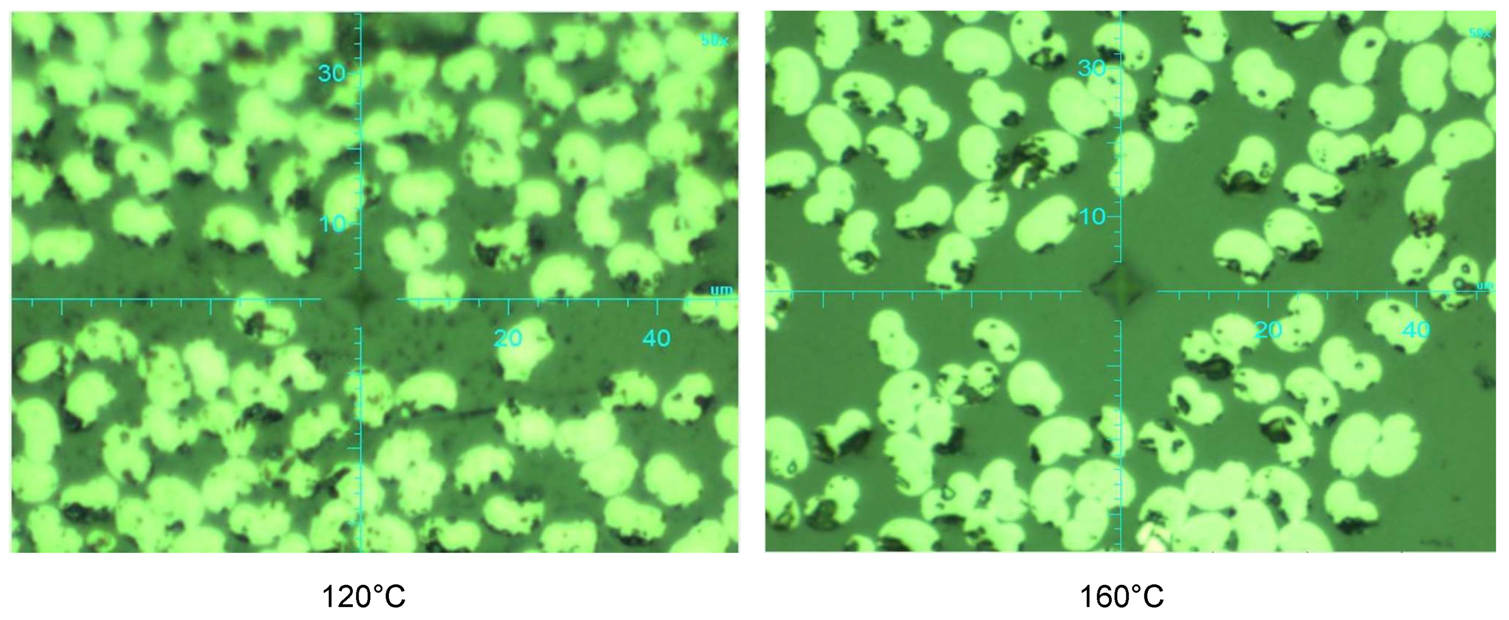
In the second part of the study, instrumental microhardness tests were carried out. When analysing the results of the instrumental indentation test, it was found that the hardness values at 120 °C are higher than at 160 °C. These results can be attributed to several causes. Firstly, macro-residues were found on the CFRP surface when the samples were joined together. Another reason could be that the prepregs were not properly overlapped during joining. The consideration was the different shear strength at 120 °C and 160 °C curing temperature. The assumption was that this resulted from different matrix properties. The strength differences in the boundary layer of hybrid specimens produced at 120 °C and 160 °C curing temperatures were taken into account. The matrix structures of the specimens produced at each curing temperature are expected to exhibit different properties. These differences are also evident in the shear strengths of fibre matrix and hybrid specimens in the boundary layer. In the present study, the focus is on the shear strength obtained in the boundary layer, and it is hypothesized that these differences are due to the matrix properties that vary with curing temperatures.
Shear tensile tests were carried out in the third part of the investigation. First, the specimens cured at 120 °C were evaluated. The results of the tests at constant speed (1 mm/min) were compared with and without preloading. The results showed that the force and displacement of the specimens with a preload of 20 MPa were higher than that of the specimens without preloading. The comparison of the fracture patterns showed that the specimens failed in the boundary layer in the tensile range. The results of the tests were then compared using the stepwise method (100 μm). Our observations revealed that the strength of the specimens with a preload of 20 MPa is higher than the specimens without preload. After the investigation of the fracture patterns, it was seen that the fracture occurred at the same location, where the fracture occurred in the middle boundary layer of the specimens with a preload of 20 MPa. Subsequently, the specimens cured at 160 °C were investigated in the same manner. The results of the tests at constant speed (1 mm/min) were compared with and without preloading. When comparing the results, it was found that the strength and displacement of the 20 MPa prestressed specimens were greater than those of the non-prestressed specimens. When comparing the fracture patterns of the specimens, both the prestressed and non-prestressed fracture patterns showed failure in the middle boundary layer. The results of the tests were then compared using the stepwise method (100 μm). According to the results of the tests with the stepwise method, it was found that the prestressed and non-prestressed results were highly far apart.
Curing the specimens at different temperatures and then examining the fracture patterns revealed interesting results. In particular, it was observed that no fracture patterns occurred in the interface as a result of curing at 120 °C. This led to a scientific questioning of the single-lap shear tensile tests performed at 120 °C. In light of these findings, it can be considered that the focus of future studies should be on 160 °C. However, it should not be forgotten that more extensive and detailed research is required.
When analysing the fracture patterns, it quickly becomes apparent that partial or almost complete adhesion failure occurs. This failure occurs almost universally on the metallic side.
Consequently, the properties of hybrid materials obtained by curing prestressed fibre materials under appropriate temperatures were experimentally investigated. Improving the mechanical material performance of the existing structure with proper manufacturing techniques is quite promising, especially in lightweight design. Based on the results, the current research is going to be further continued and detailed in the subsequent periods.

Author Contributions

Conceptualization, H.I.; methodology, H.I.; software, H.I.; validation, H.I. and S.T.; formal analysis, H.I.; investigation, H.I.; resources, T.M. and T.T.; data curation, H.I. and S.T.; writing—original draft preparation, H.I.; writing—review and editing, H.I., S.T., T.M. and T.T.; visualization, H.I.; supervision, T.M. and T.T.; project administration, H.I. and S.T.; funding acquisition, T.M. and T.T. All authors have read and agreed to the published version of the manuscript.

Funding

This research received no external funding.

Data Availability Statement

Dataset available on request from the authors.

Acknowledgments

Special thanks go to the company DMG MORI Ultrasonic Lasertec GmbH for the use of the ultrasonic milling machine for the production of the test samples.

Conflicts of Interest

The authors declare no conflict of interest.

Abbreviations

The following abbreviations are used in this manuscript:
CFRPCarbon fiber reinforced plastics
FMLFiber metal laminates
FRPFibre-reinforced plastic
MLCMultilayer Composite
PrepregPre-impregnated
UDUnidirectional
dThickness per prepreg layer [mm]
F f i b r e Fibre preload force [N]
lLength [mm]
l e x t Extensometer [mm]
L y Extension values longitudinal y-direction [mm]
wWidth [mm]
ε y Strain values longitudinal y-direction [%]
ϑ Fibre volume fraction [%]
σ f i b r e Fibre prestressing [MPa]

References

  1. Lauter, C. Entwicklung und Herstellung von Hybridbauteilen aus Metallen und Faserverbundkunststoffen für den Leichtbau im Automobil. Ph.D. Thesis, Paderborn University, Paderborn, Germany, 2014. [Google Scholar]
  2. Expertenkommission Forschung und Innovation (EFI). Gutachten zu Forschung, Innovation und Technologischer Leistungsfähigkeit Deutschlands; EFI: Berlin, Germany, 2022. [Google Scholar]
  3. Wang, Z.; Lauter, C.; Sanitther, B.; Camberg, A. Manufacturing and investigation of steel-CFRP hybrid pillar structures for automotive applications by intrinsic resin transfer moulding technology. Int. J. Automot. Compos. 2016, 2, 229–243. [Google Scholar] [CrossRef]
  4. Schürmann, H. Konstruieren mit Faser-Kunststoff-Verbunden; Springer: Berlin/Heidelberg, Germany, 2007. [Google Scholar] [CrossRef]
  5. Beaumont, P.W.R.; Soutis, C.; Hodzic, A. The Structural Integrity of Carbon Fiber Composites; Springer: Cham, Switzerland, 2017. [Google Scholar] [CrossRef]
  6. Parlevliet, P.P.; Bersee, H.E.N.; Beukers, A. Residual stresses in thermoplastic composites—A study of the literature—Part I: Formation of residual stresses. Compos. Part A Appl. Sci. Manuf. 2006, 11, 1847–1857. [Google Scholar] [CrossRef]
  7. Mostafa, N.H.; Ismarrubie, Z.N.; Sapuan, S.M.; Sultan, M.T.H. Fibre prestressed polymer-matrix composites: A review. J. Compos. Mater. 2017, 1, 39–66. [Google Scholar] [CrossRef]
  8. Shokrieh, M. Residual Stresses in Composite Materials; Woodhead Publishing, Limited: Sawston, UK, 2014; Volume 1. [Google Scholar]
  9. Vlot, A.; Vlot, A.; Gunnink, J.W. Fibre Metal Laminates; Kluwer: Dordrecht, The Netherlands, 2001. [Google Scholar]
  10. Madhukar, M.S.; Genidy, M.S.; Russell, J.D. A New Method to Reduce Cure-Induced Stresses in Thermoset Polymer Composites, Part I: Test Method. J. Compos. Mater. 2000, 34, 1882–1904. [Google Scholar] [CrossRef]
  11. Heinrich, C.; Aldridge, M.; Wineman, A.S.; Kieffer, J.; Waas, A.M.; Shahwan, K.W. The role of curing stresses in subsequent response, damage and failure of textile polymer composites. J. Mech. Phys. Solids 2013, 5, 1241–1264. [Google Scholar] [CrossRef]
  12. Mergheim, J.; Possart, G.; Steinmann, P. Modelling and computation of curing and damage of thermosets. Comput. Mater. Sci. 2012, 1, 359–367. [Google Scholar] [CrossRef]
  13. D’Mello, R.J.; Maiarù, M.; Waas, A.M. Effect of the curing process on the transverse tensile strength of fiber-reinforced polymer matrix lamina using micromechanics computations. Integr. Mater. Manuf. Innov. 2015, 1, 119–136. [Google Scholar] [CrossRef]
  14. White, S.R.; Hahn, H.T. Cure Cycle Optimization for the Reduction of Processing-Induced Residual Stresses in Composite Materials. J. Compos. Mater. 1993, 14, 1352–1378. [Google Scholar] [CrossRef]
  15. Kim, H.S.; Park, S.W.; Lee, D.G. Smart cure cycle with cooling and reheating for co-cure bonded steel/carbon epoxy composite hybrid structures for reducing thermal residual stress. Compos. Part A Appl. Sci. Manuf. 2006, 10, 1708–1721. [Google Scholar] [CrossRef]
  16. Fancey, K.S. Prestressed Polymeric Composites Produced by Viscoelastically Strained Nylon 6,6 Fibre Reinforcement. J. Reinf. Plast. Compos. 2000, 15, 1251–1266. [Google Scholar] [CrossRef]
  17. Motahhari, S.; Cameron, J. Impact Strength of Fiber Pre-Stressed Composites. J. Reinf. Plast. Compos. 1998, 2, 123–130. [Google Scholar] [CrossRef]
  18. Motahhari, S. Fibre Prestressed Composites: A Study of the Influences of Fibre Prestressing on the Mechanical Properties of Polymer Matrix Composites. Ph.D. Thesis, Queen’s University, Kingston, ON, Canada, 1998. [Google Scholar]
  19. Abdullah, O.A.; Hassan, A.K.F. Effect of prestress level on the strength of CFRP composite laminate. J. Mech. Sci. Technol. 2016, 30, 5115–5123. [Google Scholar] [CrossRef]
  20. Zhao, J.; Cameron, J. Polypropylene matrix composites reinforced with pre-stressed glass fibers. Polym. Compos. 1998, 3, 218–224. [Google Scholar] [CrossRef]
  21. Jevons, M.P. The Effects of Fibre Pre-Stressing on the Impact Performance of Composite Laminates. Ph.D. Thesis, Cranfield University, Bedford, UK, 2004. [Google Scholar]
  22. Wu, T.; Tinkloh, T.; Tröster, T.; Zinn, W.; Niendorf, T. Determination and Validation of Residual Stresses in CFRP/Metal Hybrid Components Using the Incremental Hole Drilling Method. J. Compos. Sci. 2020, 3, 143. [Google Scholar] [CrossRef]
  23. Asmael, M.; Safaei, B.; Zeeshan, Q.; Zargar, O.; Nuhu, A.A. Ultrasonic machining of carbon fiber–reinforced plastic composites: A review. Int. J. Adv. Manuf. Technol. 2021, 1, 3079–3120. [Google Scholar] [CrossRef]
  24. Koplev, A.; Lystrup, A.; Vorm, T. The cutting process, chips, and cutting forces in machining CFRP. Composites 1983, 4, 371–376. [Google Scholar] [CrossRef]
  25. Zinn, C.; Bobbert, M.; Dammann, C.; Wang, Z.; Tröster, T.; Mahnken, R.; Meschut, G.; Schaper, M. Shear strength and failure behaviour of laser nano-structured and conventionally pre-treated interfaces in intrinsically manufactured CFRP-steel hybrids. Compos. Part B Eng. 2018, 1, 173–185. [Google Scholar] [CrossRef]
Figure 1. (a) Fibre–stretching frame, (b) pressing tool, (c) new tool concept.
Jcs 08 00316 g001
Figure 2. Experimental setup.
Jcs 08 00316 g002
Figure 3. Position of extensometers.
Jcs 08 00316 g003
Figure 4. (a) Illustration of a single–lap shear specimen, (b) the miniature load frame.
Jcs 08 00316 g004
Figure 5. (a) Force–time diagram with different observation levels; (a) 0 s, (b) 5 s, (c) 10 s, (d) 16 s, (e) 21 s, (b) strain–time diagram.
Jcs 08 00316 g005
Figure 6. Strain levels at five different observation levels; (a) 0 s, (b) 5 s, (c) 10 s, (d) 16 s, (e) 21 s.
Jcs 08 00316 g006
Figure 7. Three virtual extensometers in the y-direction for single–layer prepreg at 20 MPa fibre prestressing.
Jcs 08 00316 g007
Figure 8. (a) Force–time diagram with different observation levels; (a) 0 s, (b) 7 s, (c) 14 s, (d) 21 s, (e) 27 s, (b) strain–time diagram.
Jcs 08 00316 g008
Figure 9. Strain levels at five different observation levels; (a) 0 s, (b) 7 s, (c) 14 s, (d) 21 s, (e) 27 s.
Jcs 08 00316 g009
Figure 10. Three virtual extensometers in the y-direction for seven–layer prepreg at 20 MPa fibre prestressing.
Jcs 08 00316 g010
Figure 11. Measurement location.
Jcs 08 00316 g011
Figure 12. (a) Schematic diagram of the loading scheme, (b) load–indentation depth diagram of Row 1 at 160 °C.
Jcs 08 00316 g012
Figure 13. The results of the nanoindentation tests; (a) average on row basis, (b) average on sample basis.
Jcs 08 00316 g013
Figure 14. Microscopic view (50×).
Jcs 08 00316 g014
Figure 15. (a) The results of the tests at constant speed (1 mm/min); (b) fracture patterns without prestressing (top) and with 20 MPa prestress (bottom) (at 120 °C, v = 1 mm/min).
Jcs 08 00316 g015
Figure 16. (a) The results of the stepwise test method; (b) fracture patterns without prestressing (top) and with 20 MPa prestress (bottom) (120 °C, stepwise method).
Jcs 08 00316 g016
Figure 17. (a) The results of the tests at a constant speed (1 mm/min); (b) fracture patterns without prestressing (top) and with 20 MPa prestress (bottom) (at 160 °C, v = 1 mm/min).
Jcs 08 00316 g017
Figure 18. (a) The results of the tests using the stepwise method; (b) fracture patterns without prestressing (top) and with 20 MPa prestress (bottom) (160 °C, stepwise method).
Jcs 08 00316 g018
Table 1. Production plan of specimens.
NoTemperaturePressureFibre Prestressing
1120 °C0.3 MPa20 MPa
2160 °C0.3 MPa20 MPa
Disclaimer/Publisher’s Note: The statements, opinions and data contained in all publications are solely those of the individual author(s) and contributor(s) and not of MDPI and/or the editor(s). MDPI and/or the editor(s) disclaim responsibility for any injury to people or property resulting from any ideas, methods, instructions or products referred to in the content.

