Article

Microstructural Evolution and Mechanical Behaviors of Cf/Cm-SiC-(ZrxHf1−x)C Composites with Different Carbon Matrices

1
National Key Laboratory of Science and Technology on High-Strength Structural Materials, Central South University, Changsha 410083, China
2
Science and Technology of Advanced Functional Composites Laboratory, Aerospace Research Institute of Materials and Processing Technology, Beijing 100076, China
*
Author to whom correspondence should be addressed.
J. Compos. Sci. 2024, 8(8), 303; https://doi.org/10.3390/jcs8080303
Submission received: 30 June 2024 / Revised: 19 July 2024 / Accepted: 3 August 2024 / Published: 5 August 2024
(This article belongs to the Special Issue Advanced in Ceramic Matrix Composites)

Abstract

:
In this study, two types of porous Cf/Cm composites were obtained by introducing pyrolytic carbon (PyC) and pyrolytic carbon/furan resin carbon (PyC/FRC). Subsequently, Cf/Cm-SiC-(ZrxHf1−x)C composites with different carbon matrices were prepared by introducing SiC and (ZrxHf1−x)C matrices into the porous Cf/Cm composites via the reactive melt infiltration method, specifically termed as Cf/PyC-SiC-(ZrxHf1−x)C and Cf/PyC/FRC-SiC-(ZrxHf1−x)C composites. The microstructures of the porous Cf/Cm and Cf/Cm-SiC-(ZrxHf1−x)C composites with different carbon matrices were examined, and a comprehensive analysis was conducted on microstructural evolution and mechanical behaviors of the Cf/Cm-SiC-(ZrxHf1−x)C composites. The results indicate that both Cf/Cm-SiC-(ZrxHf1−x)C composites underwent similar microstructural evolution processes, differing only in terms of evolution kinetics and final microstructure. Differences in the pore structures of porous Cf/Cm composites, as well as in the reactivities of carbon matrices, were identified as primary influencing factors. Additionally, both Cf/Cm-SiC-(ZrxHf1−x)C composites exhibited “pseudo-ductile” fracture characteristics, with flexural strengths of 214.1 ± 8.8 MPa and 149.6 ± 12.2 MPa, respectively. In the Cf/PyC-SiC-(ZrxHf1−x)C composite, crack initiation during loading primarily originated from the ceramic matrix, while in the Cf/PyC/FRC-SiC-(ZrxHf1−x)C composite, failure initially arose from the residual FRC matrix. Excessive fiber corrosion and the presence of residual low-modulus FRC matrix resulted in lower mechanical performance.

Graphical Abstract

1. Introduction

In recent decades, the development and utilization of advanced composites have garnered significant attention because of their exceptional mechanical properties and versatility in applications [1,2,3,4]. Among these, carbon fiber reinforced ceramic matrix composites (CFRCMCs) have emerged as a promising class of materials owing to their unique combination of properties, including low density, high specific strength, excellent fracture toughness, and superior resistance to corrosion and wear [5,6,7,8]. The incorporation of ceramic matrix and carbon fiber reinforcement not only overcomes the weaknesses of ceramic brittleness and poor reliability but also addresses the drawback of pure carbon composites being prone to oxidation at high temperatures [9,10,11]. As a result, CFRCMCs have garnered significant attention in various fields, such as aerospace, automotive, defense, energy, and biomedical applications [12,13,14,15,16].
To date, CFRCMCs are primarily fabricated through various techniques, including reactive melt infiltration (RMI) [17,18,19], chemical vapor infiltration (CVI) [15,20], precursor infiltration and pyrolysis (PIP) [21,22], and slurry infiltration (SI) [23,24]. Among these, RMI stands out as a method with promising industrial applications characterized by its low cost, short processing cycle, and low product porosity, among other advantages [25,26]. Typically, the RMI process encompasses two sequential steps: (1) the permeation of molten metal into the interior of porous Cf/Cm composites prefabricated with carbon matrices and (2) the ensuing reaction between the carbon matrices within the porous Cf/Cm composites and the molten metal to form ceramic matrices, culminating in the formation of CFRCMCs [27]. Evidently, porous Cf/Cm composites serve as a pivotal factor influencing the final microstructure of CFRCMCs prepared via the RMI method. Essentially, the configuration of the porous Cf/Cm composites is contingent upon both the structural composition of the carbon fiber preforms and the type and content of the carbon matrices. With the structure of the carbon fiber preforms predetermined, the type and content of the carbon matrices emerge as intrinsic variables pivotal in determining the definitive microstructure of CFRCMCs. Wang et al. [28] fabricated C/ZrC composites using phenolic resin and asphalt as carbon precursors by the RMI method, and the analysis showed noticeable distinctions in the microstructure of composites fabricated with different carbon precursors. Jiang et al. [29] prepared C/C-SiC dual matrix composites using the RMI method and demonstrated that the resin carbon matrix facilitated the infiltration and homogeneous dispersion of molten silicon compared with the pyrolytic carbon (PyC) matrix. This characteristic contributed to the attainment of higher density and a more uniform microstructure in C/C-SiC composites. In our previous work [18], the microstructure of the porous Cf/Cm composites and the carbon fiber reinforced carbon, SiC, and (ZrxHf1−x)C matrices (Cf/Cm-SiC-(ZrxHf1−x)C) composites with varying PyC content have been systematically investigated. The results indicated that an increase in the PyC content effectively facilitated the refinement of large-scale pores, while the refinement of the connected pores played a vital catalytic role in elevating the capillary force and promoting the conversion from metal to carbides. It is widely acknowledged that the microstructure of materials dictates their properties. While extensive research has been conducted on the microstructure, properties, and infiltration kinetics of CFRCMCs prepared via the RMI method, there remains a scarcity of studies regarding the microstructural evolution of CFRCMCs and the influence of final microstructure on mechanical behaviors. Therefore, a comprehensive understanding of the microstructural evolution of CFRCMCs, especially those with different carbon matrices, is needed as it is crucial for designing the composites’ structure and properties, as well as for their ultimate applications.
In this study, Cf/Cm-SiC-(ZrxHf1−x)C composites with different carbon matrices were prepared utilizing the porous Cf/Cm composites with different carbon matrices as green bodies via the RMI method. The microstructures of porous Cf/Cm and Cf/Cm-SiC-(ZrxHf1−x)C composites with different carbon matrices were examined, and a comprehensive analysis was conducted on microstructural evolution and mechanical behaviors of the Cf/Cm-SiC-(ZrxHf1−x)C composites. Furthermore, detailed discussions were conducted on the mechanical behaviors of Cf/Cm-SiC-(ZrxHf1−x)C composites with different carbon matrices and their correlation with microstructure.

2. Materials and Methods

2.1. Material Preparation

T700-polyacrylonitrile-based carbon fiber preforms with a bulk density of 0.55 g/cm3, which were prepared by needling non-woven cloths and short-cut-fiber webs, were utilized as preforms for porous Cf/Cm composites. The porous Cf/Cm composites with different carbon matrices were obtained by introducing pyrolytic carbon (PyC) and pyrolytic carbon/furan resin carbon (PyC/FRC) matrices into carbon fiber preforms, specifically termed Cf/PyC and Cf/PyC/FRC composites. Initially, the Cf/PyC composites were prepared through the CVI method, in which densities of 0.98 and 1.33 g/cm3 were achieved by adjusting the infiltration duration. Further details regarding the CVI parameters have been described elsewhere [30]. After heat treatment at 2000 °C, the Cf/PyC composite with a density of 1.33 g/cm3 was denoted as C/C-P. Subsequently, the PIP method was used to introduce the FRC matrix into the Cf/PyC composite with a density of 0.98 g/cm3. Specifically, an infiltrating agent composed of a mixed solution of furan resin (carbon source precursor) and phosphoric acid (curing agent) was introduced into the Cf/PyC composite, which had a density of 0.98 g/cm3, within a pressure vessel. Subsequent curing (60–190 °C) and pyrolysis carbonization (850 °C) successfully produced Cf/PyC/FRC composites. After heat treatment at 2000 °C, the Cf/PyC/FRC composites with a density of 1.32 g/cm3 were denoted as C/C-PF. The corresponding porosities of C/C-P and C/C-PF were measured as 27.97% and 28.69%, respectively.
The C/C-P and C/C-PF were embedded in the mixed infiltration materials in a SiC-coated graphite crucible. The mixed infiltration materials were obtained by mixing Si, Zr, and Hf powders according to molar fractions of 70.00%, 17.15%, and 12.85%, as reported in our previous work [30]. The ceramic matrices were introduced into the C/C-P and C/C-PF to obtain Cf/Cm-SiC-(ZrxHf1−x)C composites with different carbon matrices (specifically termed as Cf/PyC-SiC-(ZrxHf1−x)C and Cf/PyC/FRC-SiC-(ZrxHf1−x)C composites) via the RMI method in a high-temperature furnace with argon atmosphere at 2000 °C for 3 h. Correspondingly, the Cf/PyC-SiC-(ZrxHf1−x)C and Cf/PyC/FRC-SiC-(ZrxHf1−x)C composites were denoted as CMC-P and CMC-PF, respectively. Furthermore, the mixed infiltration materials were individually subjected to heat treatment at 1370 °C in an argon atmosphere. Concurrently, the C/C-P and C/C-PF were also subjected to RMI processing in the same environment at 1450 °C, 1550 °C, and 2000 °C without insulation, aiming to explore the microstructural evolution of Cf/Cm-SiC-(ZrxHf1−x)C composites with different carbon matrices. The resulting composites were denoted as P-1450, P-1500, P-2000, PF-1450, PF-1550, and PF-2000, respectively. The preparation flowchart of composites in this study is shown in Figure 1.

2.2. Characterization and Test

The bulk densities and open porosities of all as-prepared composites were measured using the standard Archimedes method. The pore size distribution of both porous Cf/Cm composites, with dimensions of 7 mm × 7 mm × 7 mm, was obtained using mercury intrusion porosimetry (MIP, Auto Pore IV 9500, Micromeritics, Norcross, GA, USA). The phase compositions of all composites prepared via the RMI method were determined using X-ray diffraction (XRD, Advance-D8, Cu Kα1, Bruker, Billerica, MA, USA) operating at an acceleration voltage and emission current of 40 kV and 40 mA and a scan speed of 8°/min. The microstructure and element composition of all as-prepared composites were characterized using a field emission scanning electron microscope (FESEM, Mira4, Tescan, Brno, Czech) in combination with energy dispersive spectroscopy (EDS, Xplore30. Aztec one, Oxford Instruments, Oxford, UK). The PF-1550 sample for examination via transmission electron microscopy (TEM; JEM-F200, Japan Electron Optics Laboratory LTD., Tokyo, Japan) was tailored via focused ion beam scanning electron microscopy (FIB-SEM; Helios 5 UC, Thermo Fisher, Waltham, MA, USA).
The flexural strength of both Cf/Cm-SiC-(ZrxHf1−x)C composites was evaluated using a three-point flexural test conducted on an electronic universal testing machine (Model 5969, Instron, Norwood, MA, USA). The flexural strength was calculated using the formula:
σ f = 3 P L 2 b h 2 ,
where, σ f is the flexural strength of the specimen, MPa; P is the maximum load, N; L is the span, mm; b and h are the width and thickness of the specimen, mm, respectively. The test was carried out with a span of 40 mm and a loading speed of 2.0 mm/min. The flexural specimens had dimensions of 4 mm × 10 mm × 55 mm.

3. Results and Discussion

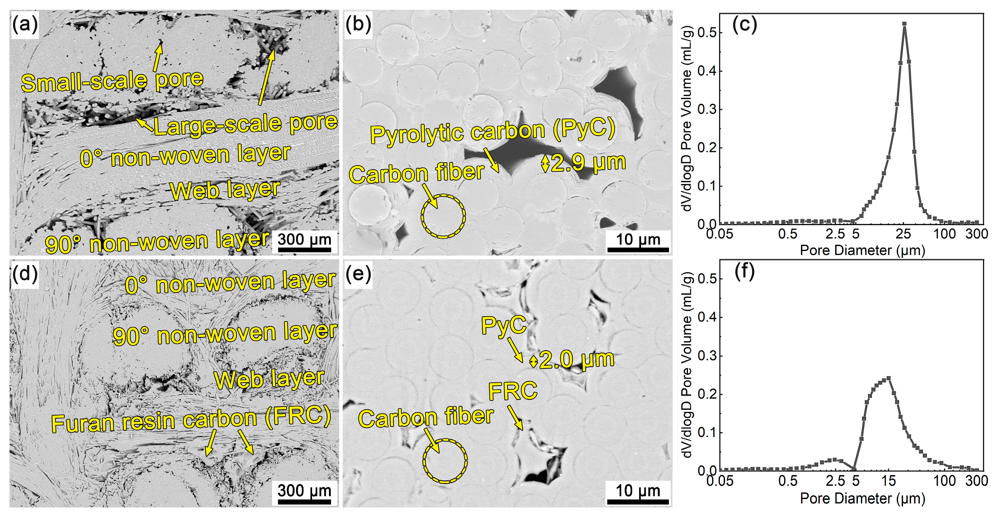
3.1. Microstructure of Porous Cf/Cm Composites

Figure 2 shows the micrographs and pore size distribution curves of porous Cf/Cm composites. As can be observed from Figure 2a, there is a periodic stacking of the non-woven layers and web layers in C/C-P (Cf/PyC composite). Large-scale pores are present between fiber bundles within the non-woven layers, the web layers, and the boundaries between neighboring layers, while small-scale pores primarily exist inside the fiber bundles. A closer examination of the non-woven layers in C/C-P, as depicted in Figure 2b, reveals a high-magnification micrograph where the PyC matrix was deposited on the carbon fibers, forming the interface layers approximately 2.9 μm in thickness. Due to the incomplete filling of the regions between carbon fibers with the PyC matrix, the pores mentioned above were formed. The quantification of the internal pores of C/C-P yielded the pore size distribution curve shown in Figure 2c. The curve illustrates that the most probable pore diameter for C/C-P is 25 μm, exhibiting a distinct unimodal distribution in pore sizes. The pore sizes are primarily distributed within the range of 5–100 μm, although a faint peak can be detected in the range of 0.5–5 μm. C/C-PF (Cf/PyC/FRC composite) exhibits structural features similar to C/C-P, but there are also differences, as shown in Figure 2d. The block-shaped FRC matrix was introduced into the Cf/PyC composite with a density of 0.98 g/cm3 to form C/C-PF. As a result, the large-scale pores in the Cf/PyC composite were effectively occupied by the block-shaped FRC matrix, resulting in smaller pores in C/C-PF compared with C/C-P. Furthermore, the high-magnification micrograph of the non-woven layer in C/C-PF shown in Figure 2e reveals that, due to a shorter infiltration duration, the PyC layers with a thickness of only 2 μm were formed. Meanwhile, the small-scale pores in the fiber bundles were further filled by the FRC matrix, resulting in a reduction in the sizes of the pores. The changes in pore structures caused by the introduction of the FRC matrix can be directly seen from the alterations in the pore size distribution curve. Figure 2f presents the pore size distribution curve of C/C-PF. The obvious bimodal distribution characteristics in pore sizes can be observed. The pore sizes of C/C-PF are primarily distributed in the ranges of 0.5–5 and 5–100 μm, with a most probable pore diameter of 15 μm. Evidently, the scale of pores in the C/C-PF significantly decreased compared with C/C-P. The incorporation of the FRC matrix effectively regulated the pore structures of porous Cf/Cm composites. Furthermore, the small-scale pores distributed in the range of 0.5–5.0 μm can be inferred to originate primarily from the fiber bundles of the C/C-PF. The FRC matrix further reduced the pore sizes inside the fiber bundles of the Cf/PyC composite, making the faint peak in the 0.5–5.0 μm range in Figure 2c more prominent in Figure 2f. In conclusion, the utilization of different carbon matrices in porous Cf/Cm composites led to substantial variations in microstructure, which may influence the microstructure and mechanical behaviors of the CFRCMCs prepared through subsequent RMI processes.

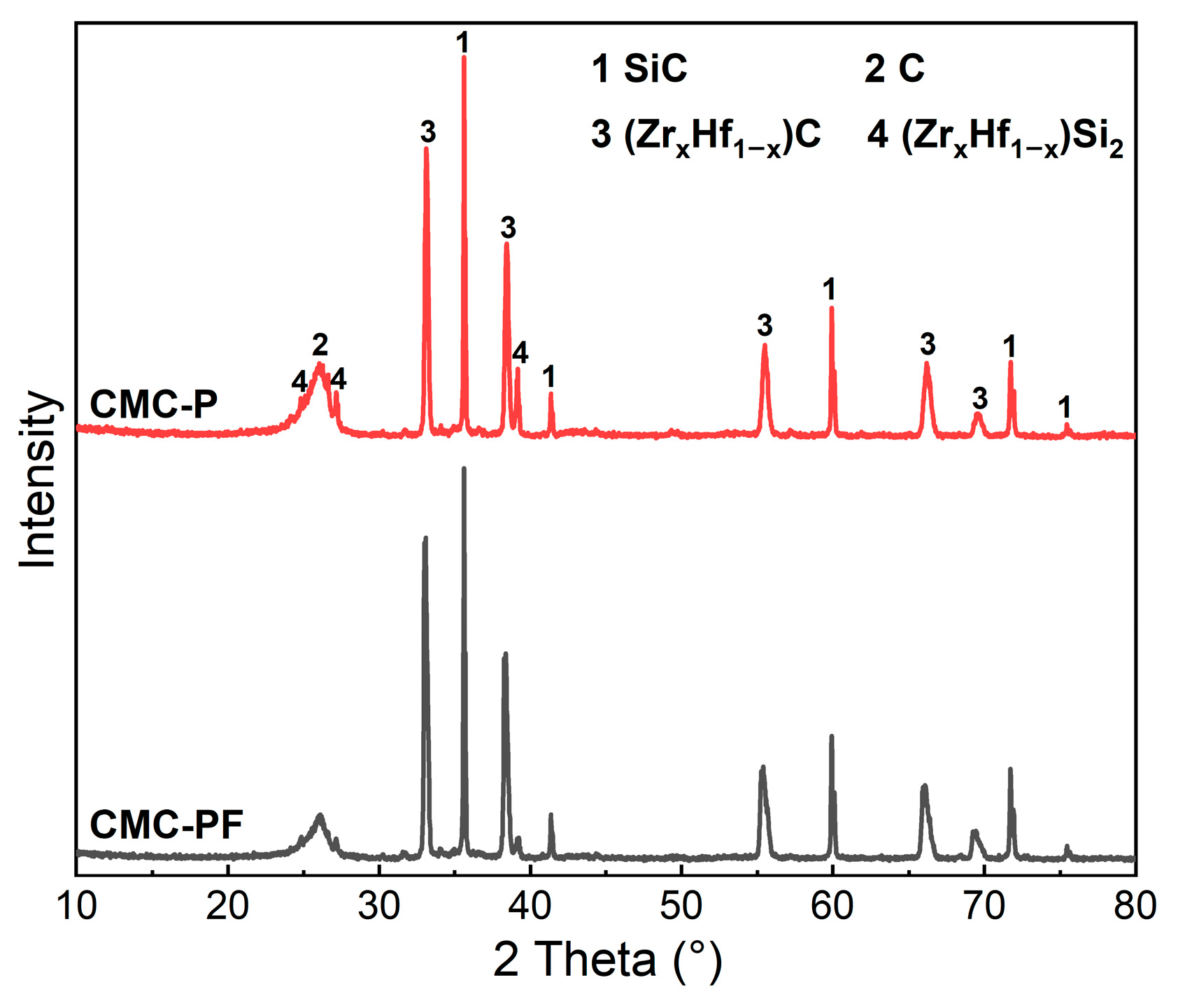
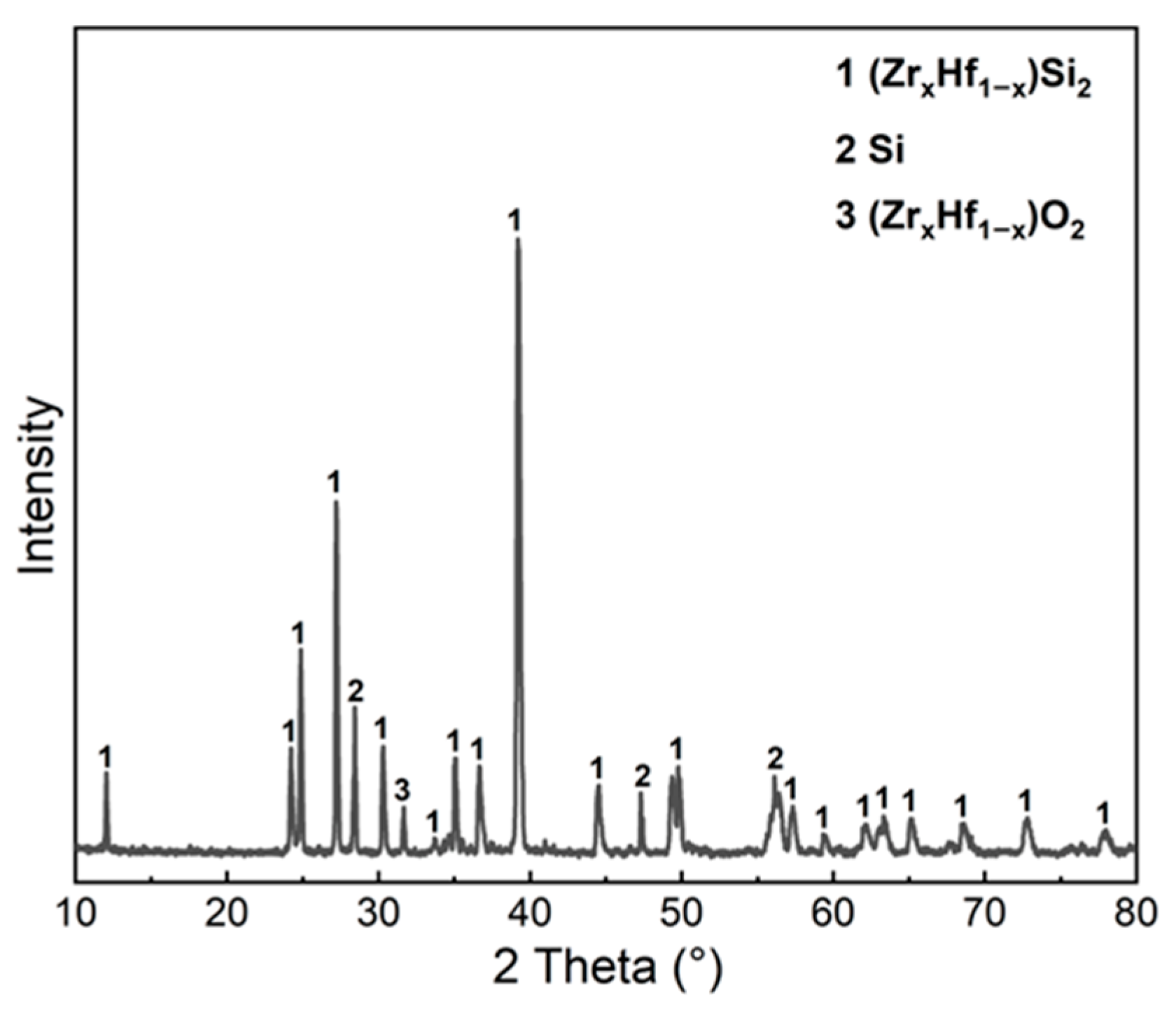
3.2. Phase Composition and Microstructure of Cf/Cm-SiC-(ZrxHf1−x)C Composites

Figure 3 shows the XRD patterns of Cf/Cm-SiC-(ZrxHf1−x)C composites. It is evident that the Cf/Cm-SiC-(ZrxHf1−x)C composites consist of the C, SiC, (ZrxHf1−x)C phases and a small amount of (ZrxHf1−x)Si2 phases. The formation of solid solution phases has been detailed in our previous work [18]. Furthermore, there are significant differences in the phase content of both types of Cf/Cm-SiC-(ZrxHf1−x)C composites. Specifically, CMC-PF exhibits a lower content of C and (ZrxHf1−x)Si2 compared with CMC-P. The refinement of large-scale pores in Cf/PyC/FRC composite played a pivotal role. The reduction in pore size effectively minimized the space occupied by molten metal, thus shortening the diffusion path of carbon atoms toward the center of the molten metal, facilitating the maximization of ceramic formation. Additionally, the high reactivity of FRC might result in further consumption of molten metal and C, which could be another key factor.
Figure 4 shows the micrographs of the Cf/Cm-SiC-(ZrxHf1−x)C composites. From Figure 4a,c, it is evident that the connected large-scale and small-scale pores of the porous Cf/Cm composites were adequately filled with various phases, resulting in a relatively high degree of densification for Cf/Cm-SiC-(ZrxHf1−x)C composites. In CMC-P, intact fiber bundles within the non-woven layers, residual carbons (carbon fibers, PyC) within the web layers, SiC, (ZrxHf1−x)C, and a minor amount of (ZrxHf1−x)Si2 are observed. In contrast, within CMC-PF, the fiber bundles within the non-woven layers have been partially corroded by the molten metal during the RMI process, which was attributable to the incomplete filling of the PyC matrix within C/C-PF because of the shorter CVI time. This may potentially have adverse effects on the mechanical properties of CMC-PF. Additionally, although C/C-PF possesses smaller pores and more carbon content than C/C-P in the web layers, CMC-PF prepared from C/C-PF shows fewer residual carbons (carbon fibers, PyC, FRC) within the web layers after the RMI, with a large amount of SiC and (ZrxHf1−x)C observed, and no (ZrxHf1−x)Si2. This suggests that the introduction of FRC evidently accelerated the consumption of carbon and (ZrxHf1−x)Si2 during the RMI process, leading to the formation of more ceramic phases. Furthermore, from Figure 4b,d, it can be observed that both Cf/Cm-SiC-(ZrxHf1−x)C composites exhibit similar and intriguing phase distributions. Specifically, proceeding from the carbon phase towards the central region of original pores, the SiC layer, (ZrxHf1−x)C layer, and large-scale SiC are present in the sequence. This microstructure evolved during the RMI process, necessitating further detailed investigation.

3.3. Microstructural Evolution of Cf/Cm-SiC-(ZrxHf1−x)C Composites

Understanding the microstructural evolution of composites holds significant importance in elucidating the inherent correlation between the microstructure and properties of composites, as well as guiding the design and applications of such materials.
The XRD pattern of reaction products of mixed infiltration materials after heat treatment at 1370 °C is shown in Figure 5, which reveals that the reaction products consist mainly of (ZrxHf1−x)Si2 and Si, with only a small amount of Zr/Hf being oxidized to (ZrxHf1−x)O2. Consequently, it can be inferred that the mixed infiltration materials will preferentially undergo a solid-phase transformation before melting in the RMI process, resulting in the formation of an infiltration mixture primarily composed of (ZrxHf1−x)Si2 and Si.
Figure 6 shows the XRD patterns of P-1450 and PF-1450 (the composites prepared via the RMI method at 1450 °C without insulation). It can be observed that P-1450 consists of C and SiC phases, and the diffraction peak of SiC is extremely weak. Contrastingly, PF-1450 comprises C, SiC, (ZrxHf1−x)Si2, and trace amounts of (ZrxHf1−x)C. The diffraction peaks of SiC and (ZrxHf1−x)C indicate that the molten infiltration mixture has infiltrated into PF-1450 and reacted with carbon matrices. Furthermore, the presence of sharp diffraction peaks for C and (ZrxHf1−x)Si2 indicates that the reaction between the metals and the carbon matrices was incomplete at 1450 °C. Consequently, a substantial portion of the metallic constituents did not completely react to form carbides, instead remaining in the (ZrxHf1−x)Si2 form, while the carbon was not extensively consumed. Moreover, no diffraction peak corresponding to the Si phase is observed in either type of composite, suggesting that Si has essentially reacted completely with other constituents. As a result, it can be inferred that the Si may exhibit a greater propensity to react with carbon to form carbides compared with (ZrxHf1−x)Si2.
Figure 7 shows the micrographs and EDS results of P-1450 and PF-1450. It can be observed from Figure 7a that although the process temperature exceeded the melting point of Si (1414 °C), no prior infiltration of molten Si into the Cf/PyC composite was observed. As mentioned earlier, the mixed infiltration materials underwent chemical reactions in the solid state, forming an infiltration mixture primarily composed of (ZrxHf1−x)Si2 and Si. The melting points of ZrSi2 and HfSi2 are approximately 1627 °C and 1543 °C, respectively, suggesting that the melting point of (ZrxHf1−x)Si2 should fall between 1543 °C and 1627 °C [10]. Based on this, it can be speculated that no molten solid silicides sintered to form a porous medium at 1450 °C, and molten Si was adsorbed by capillary forces of the porous medium, resulting in a solid–liquid mixture state. This prevented the molten Si from preferentially infiltrating the pores of the Cf/PyC composite. It was only following the melting of (ZrxHf1−x)Si2 that the molten mixture was able to infiltrate the porous Cf/Cm composites. Furthermore, a thin layer of substance inconsistent with its grayscale is found on the surface of the PyC. According to the EDS result in Figure 7d, this thin layer can be identified as SiC, consistent with the XRD result. Si has a surface vapor pressure of about 10−1 Pa at 1400 °C [31], leading to significant volatilization of Si during the heating process. The evaporated Si infiltrated the interior of the Cf/PyC composite and reacted with the PyC to form a SiC layer. This is beneficial for subsequent melt infiltration, as SiC exhibits better wettability for molten metals compared with carbon [32].
In contrast to P-1450, the surface of PF-1450 has been partially infiltrated by the infiltration mixture, resulting in the formation of two principal phases with varying brightness, except for the carbon phase, as illustrated in Figure 7b. The EDS results depicted in Figure 7e,f identified the grey phase as SiC, while the white phase corresponded to (ZrxHf1−x)Si2. SiC was mainly formed by the reaction between Si and C, presenting a layered structure closely bound to PyC or carbon fibers. Therefore, it can be inferred that the nanoscale SiC layer formed by the interaction between Si vapor and carbon matrices cannot block the reaction between the molten mixture and the carbon matrices and may even have dissolved in the molten infiltration mixture. Furthermore, the locally observed high-magnification morphology on the surface of PF-1450, as shown in Figure 7c, along with the EDS result in Figure 7e, reveals the presence of a mixture of Si and porous solid (ZrxHf1−x)Si2. This substantiated the previous speculation that Si preferentially melted but could not infiltrate independently. However, despite the melting point of (ZrxHf1−x)Si2 exceeding 1543 °C, the infiltration mixture exhibited melting and limited infiltration at 1450 °C. This phenomenon may be attributable to the exothermic reaction between the infiltration mixture and the Cf/PyC/FRC composite. Many studies [32,33,34,35] have indicated that the reactions between metal compounds and carbon were exothermic. For example, the reaction enthalpy for silicon and carbon involved in this study can be acquired from the HSC thermochemical database:
Si ( l ) + C ( s ) = SiC ( s )       [ H 1723 K = 122.592   kJ ]
Sangsuwan et al. [36] also observed a sharp local temperature increase exceeding 500 °C within seconds of contact between molten Si and a carbon preform during the RMI process. Moreover, Jiang et al. [29] experimentally found that a 2–7 μm thick SiC layer formed when molten Si reacted with resin carbon at 1550 °C. Conversely, molten Si only interacted with the outermost layer of PyC at the same temperature, forming a thinner SiC layer. This proved that resin carbon with higher reactivity was more prone to react with metals and their compounds, generating more heat per unit time. Based on the above, the melting and infiltration of (ZrxHf1−x)Si2 and Si mixture into the Cf/PyC/FRC composite at 1450 °C can be attributable to the increased heat released from the reaction of the mixture with the Cf/PyC/FRC composite compared with the Cf/PyC composite. This resulted in a significant increase in local temperature at the surface of the Cf/PyC/FRC composite, surpassing the melting point of (ZrxHf1−x)Si2, causing the infiltration mixture to melt and infiltrate. However, at 1450 °C, the infiltration mixture did not fully infiltrate both porous Cf/Cm composites, possibly due to insufficient instantaneous heat generation from the reaction between the molten mixture and the carbon matrices at this temperature, hindering complete melting of the mixture and the initiation of cascade reactions.
Figure 8 shows the XRD patterns of P-1550 and PF-1550 (the composites prepared via the RMI method at 1550 °C without insulation). Both composites exhibit identical phase compositions, including C, SiC, (ZrxHf1−x)Si2, and (ZrxHf1−x)C phases. The presence of diffraction peaks for SiC and (ZrxHf1−x)C indicates that the molten infiltration mixture had successfully infiltrated into both porous Cf/Cm composites, undergoing chemical reactions with the carbon. However, the characteristic diffraction peaks of (ZrxHf1−x)Si2 can also be notably observed, suggesting an incomplete reaction between (ZrxHf1−x)Si2 and carbon. Importantly, PF-1550 contains a higher proportion of carbides and a lower amount of (ZrxHf1−x)Si2 compared with P-1550. This finding provides evidence that the introduction of FRC can promote the reactions between metal compounds and carbon in the RMI process.
Figure 9 shows the micrographs of P-1550 and PF-1550. It can be seen from Figure 9a that the infiltration mixture has infiltrated extensively into the Cf/PyC composite to produce P-1550, although there are still unfilled pores. PF-1550, on the other hand, exhibits a dense microstructure that is filled, which is closely related to the fact that the reaction between FRC and metal compounds can release more heat per unit of time. Furthermore, the high-magnification microstructures of the web layers in P-1550 and PF-1550 are shown in Figure 9b,e, respectively. It can be seen that the web layers of both composites have similar phase distribution patterns, with original large-scale pores being filled with SiC, (ZrxHf1−x)C, and (ZrxHf1−x)Si2 phases. Among them, the (ZrxHf1−x)Si2 phase is mainly distributed in the middle of the original pores, and towards the carbon phase, there are nearly continuous SiC layers and discontinuous (ZrxHf1−x)C layers in sequence. From the insets in the upper right corner, it can be found that there is a high content of Si and C elements between the carbon and the (ZrxHf1−x)C layers, inferring the presence of a layer of nanoscale SiC tightly bound to the carbon. On the other hand, the high-magnification microstructures of the non-woven layers in P-1550 and PF-1550 are illustrated in Figure 9c,f. It can be observed that the original small-scale pores within the non-woven layers of P-1550 are filled with the SiC, (ZrxHf1−x)C, and (ZrxHf1−x)Si2 phases, with a phase distribution similar to that of the web layers. However, a localized alteration in phase distribution is evident from the inset in the top right corner of Figure 9c: the central region of the original pores is predominantly occupied by the SiC phase and towards the carbon phase, followed by the (ZrxHf1−x)C layers and SiC layers. This is consistent with the phase distribution within PF-1550 depicted in Figure 9f, as (ZrxHf1−x)Si2 in the original small-scale pores has all reacted to form SiC and (ZrxHf1−x)C. This indicates that the microstructural evolution processes of both composites were similar but with differences arising from kinetic disparities attributable to differences in the pore structures of the Cf/PyC and Cf/PyC/FRC composites, as well as in the reactivities of the PyC and FRC matrices.
The microstructure proximal to the interfaces of PF-1550 was characterized using the TEM, as depicted in Figure 10. Figure 10a displays the high-angle annular dark field (HAADF) image near these interfaces. Comparing the grayscale variations observed in Figure 10a with the EDS result in Figure 10b reveals that PF-1550 primarily consists of carbon (black phase), SiC (dark gray phase), light gray phase, and white phase. Figure 10c exhibits a high-resolution image of the carbon/SiC interface (region C in Figure 10a). Analysis shows an interplanar distance of 0.252 nm for SiC, corresponding to the (111), consistent with the reference value in PDF04-010-5699. This directly confirms the presence of nanoscale SiC layers tightly bound to the carbon phase, as previously inferred. Regarding the light gray and white phases, both contain elements Hf, Zr, C, and Si, with their primary distinction being the Si content. Based on the XRD result in Figure 8 and the EDS result in Figure 10b, it is inferred that the light gray and white phases may be (ZrxHf1−x)C with solid-dissolved Si. Figure 10d–f respectively illustrate high-resolution images of the SiC/light gray phase interface (region D in Figure 10a), the white phase region (region E in Figure 10a), and the white phase/SiC interface (region F in Figure 10a). It can be observed from Figure 10e,f that the interplanar distance of the white phase for the (111) is 0.271 nm, indicative of a face-centered cubic structure. The interplanar distance is slightly larger than the reference value for the (111) of HfC in PDF04-003-6210, suggesting potential interstitial solid solution formation of Si in (ZrxHf1−x)C. Meanwhile, Figure 10d reveals that the light gray phase exhibited similar high-resolution features and elemental distributions to the white phase, implying it is a (ZrxHf1−x)C phase with a higher Si incorporation. Therefore, it is inferred that the formation time of the nano-SiC layer was shorter than that of other carbide layers so that silicon atoms did not have time to diffuse to the surface of the carbon phase and generate interstitial solid solutions within (ZrxHf1−x)C.
All in all, there exist certain differences in the phase distributions of composites prepared at 1550 °C and those prepared at 1450 °C. Initially, at 1450 °C, only transient melting of (ZrxHf1−x)Si2 occurred, with minimal bond-breaking, and the molten infiltration mixture was primarily composed of Si and (ZrxHf1−x)Si2. Compared with (ZrxHf1−x)Si2, Si exhibited a greater tendency to react with carbon to form carbides; thus, nearly all dissolved and diffused carbon reacted with fully molten Si, resulting in the formation of SiC grain on the carbon phase surface. However, as the temperature increased, the bond-breaking of (ZrxHf1−x)Si2 intensified, generating numerous free Zr/Hf atoms. Studies in the relevant literature [10,37] indicate that Zr/Hf atoms possess stronger capturing capabilities for carbon atoms than Si atoms. The increasing quantity of Zr/Hf atoms continuously reacted on the surface of the carbon phase to generate (ZrxHf1−x)C grains, forming discontinuous (ZrxHf1−x)C layers. Once the Zr/Hf atoms near the carbon phase were completely consumed, residual Si near the carbon phase spontaneously formed nanoscale SiC layers in situ due to the discontinuity of (ZrxHf1−x)C layers.
Figure 11 shows the XRD patterns of P-2000 and PF-2000 (the composites prepared via the RMI method at 2000 °C without insulation). Evidently, the composites prepared at 2000 °C exhibit identical phase compositions to those prepared at 1550 °C, yet they exhibit higher/lower levels of carbides/silicides content. P-2000 features lower/higher carbides/silicides content than CMC-P. These findings indicate that increasing the process temperature and extending the insulation time can facilitate the transformation of silicides into carbides. Regarding PF-2000, it displays phase content similar to CMC-PF, suggesting that the introduction of FRC can significantly promote the reaction between carbon and molten metal.
Figure 12 shows the micrographs of P-2000 and PF-2000. From Figure 12a,d, both composites have undergone complete infiltration during the RMI process and exhibited remarkably high densification post-RMI. Within P-2000, a significant amount of (ZrxHf1−x)Si2 is observed, while only trace amounts of (ZrxHf1−x)Si2 remain within the PF-2000. According to Archimedes’ method, the porosities of P-2000 and PF-2000 were measured to be 4.09% and 3.60%, respectively, which were close to the porosities of CMC-P and CMC-PF. However, their densities were measured to be 2.78 and 2.88 g/cm3, respectively, significantly lower than the densities of CMC-P and CMC-PF (2.91 and 2.96 g/cm3). It is well known that the formation of carbides through the reactions between carbon and metals typically involves volume contraction. Taking Equation (2) as an example, the volumes of each phase before and after the reaction can be calculated by Equation (3):
V = ( n × M ) / ρ ,
where n is the amount of substance, mol; M is molar mass, g/mol; and ρ is density, g/cm3. Taking ρ S i , ρ C , and ρ S i C as 2.33, 1.80, and 3.20 g/cm3 respectively. It can be determined through calculations that V S i C / ( V S i + V C ) is 0.67. The consumption of carbon can provide more accommodation for the post-generated carbides. Therefore, it can be inferred that the prolonging of insulation time allowed for the continuous dissolution and diffusion of the carbon phase, with more carbon sources participating in the reaction with the infiltration mixture. Simultaneously, during the insulation process, the majority of the infiltration mixture within the composites remained in a molten state, facilitating the replenishment of newly formed spaces resulting from volume contraction due to the reaction between carbon and the infiltration mixture. As a consequence, Cf/Cm-SiC-(ZrxHf1−x)C composites with higher ceramic content and density were formed.
Figure 12b,c,e,f present the magnified micrographs of P-2000 and PF-2000. As the temperature increased, the phase distribution within the web layers (characterized by large-scale pores) of P-2000 (Figure 12b) remained identical to that observed in P-1550 (Figure 9b). Specifically, the (ZrxHf1−x)Si2 phase was primarily distributed in the middle of the original pores. Towards the carbon phase, there were discontinuous layers of SiC and (ZrxHf1−x)C, as well as continuous SiC layers in sequence. However, the phase distribution within the non-woven layers (characterized by small-scale pores) of P-2000 (Figure 12c) became similar to that observed in PF-2000 (Figure 12e). The reduction in pore size and the introduction of FRC both effectively promoted the kinetic process from silicides to carbides. Additionally, as shown in the upper right corner inset of Figure 12e, numerous voids were observed within the (ZrxHf1−x)C layer, directly confirming its discontinuity. Moreover, Figure 12f reveals a distinct region where Si reacted with C to form SiC between the (ZrxHf1−x)C and FRC matrix, indicating the gradual diffusion of Si towards the interior of the FRC matrix and the in-situ formation of SiC. This suggests that the SiC layer at the carbon interface may form later than the (ZrxHf1−x)C phase, possibly even as the last phase to form. Otherwise, the PF-2000 will have a thicker SiC layer than P-2000, but the opposite is true. Based on this, it can also be inferred that the formation of the SiC layer closely bound to the carbon phase is independent of the Si content in the melt. Jiang et al. [38] prepared Cf/ZrC-SiC composites using a Zr−8.8Si alloy via RMI method. The results indicated that a continuous and dense SiC layer was in contact with the carbon phase, consistent with the inference in this work. Considering the comprehensive analysis provided above, it can be inferred that designing material interface phases based on differences in reaction priority may be a promising approach.
Based on the above analysis, it can be known that both Cf/PyC-SiC-(ZrxHf1−x)C and Cf/PyC/FRC-SiC-(ZrxHf1−x)C composites underwent similar microstructural evolution processes. This process can be primarily divided into the solid-phase reaction of mixed infiltration materials, evaporation and infiltration of silicon, diffusion and dissolution of carbon, formation of discontinuous carbide layers, formation of SiC layers bound to the carbon, and the formation of large-scale carbides during the cooling process. However, due to the variations in the pore structure of Cf/PyC and Cf/PyC/FRC composites, as well as differences in the reactivity of the PyC and FRC matrices, there were certain discrepancies in the reaction kinetics and final microstructure of both Cf/Cm-SiC-(ZrxHf1−x)C composites. Through comprehensive analysis, the microstructural evolution of both Cf/Cm-SiC-(ZrxHf1−x)C composites during the RMI process was inferred, and the corresponding model was constructed, as shown in Figure 13. Specifically, as follows:
(I) During the heating process, the solid-phase reaction of mixed infiltration materials first occurred, forming an infiltration mixture mainly composed of Si and (ZrxHf1−x)Si2 (Figure 13a,f).
(II) When the temperature reached the melting point of Si, molten Si formed a solid–liquid mixture with solid (ZrxHf1−x)Si2, which failed to infiltrate porous Cf/Cm composites. However, Si evaporated and infiltrated into porous Cf/Cm composites in gaseous form, reacting with the carbon matrices to generate nanoscale SiC layers (Figure 13b,g).
(III) The infiltration mixture reacted with the carbon on the surface of porous Cf/Cm composites, releasing a large amount of heat. When the surface temperature exceeded the melting point of (ZrxHf1−x)Si2, the entire infiltration mixture began to infiltrate into porous Cf/Cm composites. The FRC matrix with higher reactivity was more prone to react with metals and their compounds, generating more heat per unit time, thus facilitating a faster melting of the infiltration mixture. Carbon atoms diffused into the molten infiltration mixture, and the nanoscale SiC layers dissolved until direct contact between the carbon and the molten infiltration was allowed. Si preferentially reacted with carbon over (ZrxHf1−x)Si2, forming SiC grains on the surface of the carbon phase (Figure 13c,h).
(IV) As the temperature increased, the bond-breaking of (ZrxHf1−x)Si2 intensified, generating numerous free Zr/Hf atoms. These Zr/Hf atoms combined with carbon atoms on the surface of the carbon phase to generate (ZrxHf1−x)C grains, forming discontinuous (ZrxHf1−x)C layers (Figure 13d,i).
(V) During the insulation process, the discontinuity of the carbide layers allowed for continuous dissolution of carbon into the molten infiltration mixture. Meanwhile, new carbides continued to form on the surface of the carbon phase, and the (ZrxHf1−x)C grains predominated in regions with high carbon atom concentrations (near the carbon phase). Due to its weaker competition for carbon atoms, Si and carbon atoms combined to form SiC grains in other regions. Simultaneously, when the Zr/Hf atoms near the carbon phase were completely consumed, Si atoms diffused through the discontinuous (ZrxHf1−x)C layers to form a continuous SiC layer on the surface of the carbon phase. The larger pore scale of the Cf/PyC composite resulted in a relative insufficiency of carbon sources in the molten infiltration mixture, leading to the residual presence of some (ZrxHf1−x)Si2 in the Cf/PyC-SiC-(ZrxHf1−x)C composite (Figure 13e). In comparison, the Cf/PyC/FRC composite possessed a smaller pore scale and FRC matrix with higher reactivity, resulting in an exceptionally high carbide generation rate in the Cf/PyC/FRC-SiC-(ZrxHf1−x)C composite, and ultimately leaving a certain amount of block-shaped FRC (Figure 13j).

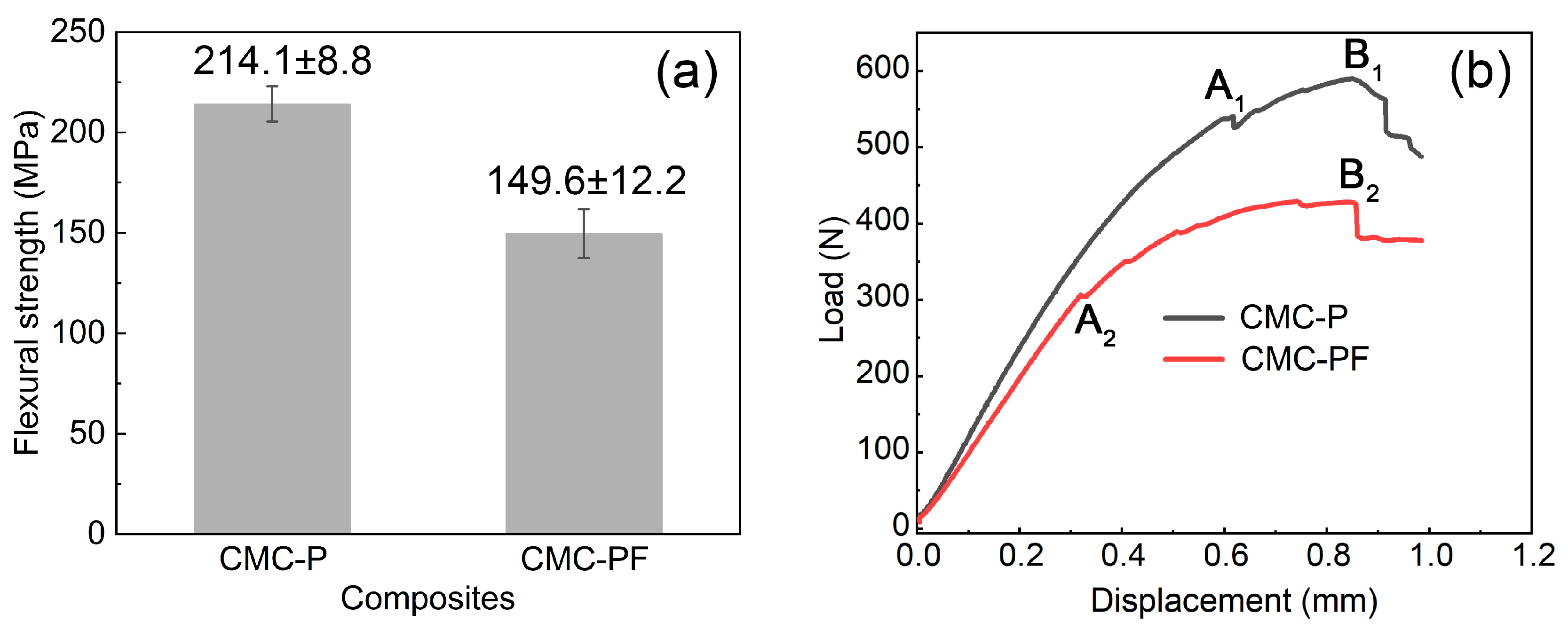
3.4. Mechanical Behaviors of Cf/Cm-SiC-(ZrxHf1−x)C Composites

Figure 14 illustrates the flexural strength (a) and load-displacement curves (b) of Cf/Cm-SiC-(ZrxHf1−x)C composites. As shown in Figure 14a, the average flexural strength of CMC-P is 214.1 ± 8.8 MPa, which exceeds that of CMC-PF at 149.6 ± 12.2 MPa. The load-displacement curves presented in Figure 14b indicate that both composites did not undergo catastrophic failure and exhibited a “pseudo-ductile” fracture, characterized by a gradual staircase-like descent after reaching the peak load. During the OA1 and OA2 stages, the curves exhibit nearly linear variations, indicating the elastic deformation of the Cf/Cm-SiC-(ZrxHf1−x)C composites. The slopes of the OA1 and OA2 segments can reflect the flexural modulus of the Cf/Cm-SiC-(ZrxHf1−x)C composites. Clearly, CMC-P possesses a higher modulus compared with CMC-PF. Gibson conducted a mechanical analysis of symmetric laminated composite beams, deriving the formula for the effective flexural modulus of symmetric laminated composite beams as shown in Equation (4) [39] (pp. 243–246):
E c = 8 h 3 j = 1 N / 2 E x j ( z j 3 z j 1 3 ) ,
where E c is the effective flexure modulus of the composites; h is the total thickness of the composites; N is the total number of layers; z j is the distance from the reference plane to the outer side of the j-th layer; E x is the modulus of the j-th layer within the composites. From Equation (3), it can be deduced that the effective flexure modulus of composites depends on the layer sequence and the modulus of individual layers. In this work, the sampling for flexure tests strictly controlled the same layer sequence of different specimens. Therefore, the effective flexure modulus of the composites depends on the modulus of individual layers, namely, the 0° non-woven layers, the 90° non-woven layers, and the web layers, with the web layers exhibiting the greatest variation in modulus among different composites. The modulus of the web layers can be calculated approximately using the rule of mixtures [40]:
E w = i = 1 n E i V i ,
where E w is the modulus of the web layers; E i and V i are the modulus and volume fraction of the i-th component within the web layers. For resin carbon, the modulus is only in the range of 15–40 GPa [41], which is significantly lower than that of ceramics and carbon fibers. During the process of elastic deformation, both the fibers and the matrix in the composites bore the load jointly. In CMC-PF, the presence of an unreacted blocky FRC matrix with low modulus may contribute to its lower modulus. When the load reached A2, cracks were initiated at the low-modulus FRC and propagated continuously within the CMC-PF (A2B2 stage). The faster initiation and propagation of cracks led to a more pronounced stress concentration. When the load reached B2, fibers fractured and pulled out, leading to the complete failure of CMC-PF. In CMC-P, cracks were initiated within the ceramic matrix only when the load reached A1, and fiber fracture and pullout began at B1.
Figure 15 depicts the micrographs of the fracture cross-section of Cf/Cm-SiC-(ZrxHf1−x)C composites. It can be observed that significant fiber pullout occurred in both composites, indicating their “pseudo-ductile” characteristics. From Figure 15a, it can be seen that larger cracks originated between the ceramic matrix within CMC-P, while smaller cracks at the fibers interface resulted from the development of larger cracks within the ceramic matrix. Contrastingly, Figure 15c reveals that cracks in CMC-PF initially originated at the FRC matrix, directly corroborating the earlier analysis and elucidating the reason for the lower strength of CMC-PF. Additionally, corroded carbon fibers were identified in Figure 15b,d. Carbon fibers are well-known reinforcements in composites and play a primary load-bearing role. As mentioned earlier, CMC-PF featured thinner protective layers (PyC) and higher reaction temperatures (more vigorous reaction between FRC and molten infiltration mixture); this potentially led to increased fiber corrosion, as observed in Figure 15d. Excessive fiber corrosion may be another reason for the lower flexural strength of CMC-PF. However, the introduction of FRC remains a viable option for preparing ceramic matrix composites with higher ceramic phase content at lower temperatures.

4. Conclusions

Cf/PyC-SiC-(ZrxHf1−x)C and Cf/PyC/FRC-SiC-(ZrxHf1−x)C composites were prepared utilizing the porous Cf/PyC and Cf/PyC/FRC composites as green bodies via the RMI method. The introduction of a highly reactive FRC matrix refined the pore sizes in the Cf/PyC/FRC composite, which expedited the chemical reactions between carbon and metals during the RMI process, ultimately resulting in the formation of increased ceramic content within the Cf/PyC/FRC-SiC-(ZrxHf1−x)C composite. In contrast, the Cf/PyC-SiC-(ZrxHf1−x)C composite exhibited slower chemical reaction rates and higher residuals of carbon and (ZrxHf1−x)Si2. Despite their disparities in evolution kinetics and final microstructures, both types of Cf/Cm-SiC-(ZrxHf1−x)C composites underwent similar microstructural evolution processes, encompassing the solid-phase reaction of mixed infiltration materials, evaporation and infiltration of silicon, diffusion and dissolution of carbon, formation of discontinuous carbides layers, formation of SiC layers bound to the carbon, and the formation of large-scale carbides during the cooling process. A comprehensive analysis of microstructural evolution suggests that designing material interfaces based on differences in reaction priority may be a promising approach. Both Cf/Cm-SiC-(ZrxHf1−x)C composites exhibited “pseudo-ductile” fracture characteristics, with flexural strengths of 214.1 ± 8.8 MPa and 149.6 ± 12.2 MPa, respectively. In the Cf/PyC-SiC-(ZrxHf1−x)C composite, crack initiation during loading primarily originated from the ceramic matrix, while in the Cf/PyC/FRC-SiC-(ZrxHf1−x)C composite, failure initially arose from the residual FRC matrix. Excessive fiber corrosion and the presence of residual low-modulus FRC matrix resulted in lower mechanical performance of the Cf/PyC/FRC-SiC-(ZrxHf1−x)C composite. These results offered valuable insights into the design and applications of CFRCMCs.

Author Contributions

Conceptualization, Y.W., H.Z., X.X., J.W. and T.L.; methodology, Z.L. and Z.Y.; validation, Y.W.; formal analysis, Z.L. and Q.L.; investigation, Z.L., Z.Y. and C.L.; resources, J.W. and T.L.; data curation, Z.L.; writing—original draft preparation, Z.L.; writing—review and editing, Y.W.; visualization, Z.L.; supervision, J.W. and T.L.; project administration, Y.W.; funding acquisition, X.X. All authors have read and agreed to the published version of the manuscript.

Funding

This research was funded by the National Key Research and Development Program of China (grant number 2022YFB3706103) and the Major Project of Science and Technology Plan of Changsha (grant number kh2102018).

Data Availability Statement

Data are available upon request from the authors.

Conflicts of Interest

The authors declare no conflict of interest.

References

  1. Mikinka, E.; Siwak, M. Recent advances in electromagnetic interference shielding properties of carbon-fibre-reinforced polymer composites—A topical review. J. Mater. Sci. Mater. Electron. 2021, 32, 24585–24643. [Google Scholar] [CrossRef]
  2. Dai, H.; Dai, W.; Hu, Z.; Zhang, W.; Zhang, G.; Gu, R. Advanced composites inspired by biological structures and functions in nature: Architecture design, strengthening mechanisms, and mechanical-functional response. Adv. Sci. 2023, 10, 2207192. [Google Scholar] [CrossRef] [PubMed]
  3. Liu, Y.; Fu, Q.G.; Wang, B.B.; Liu, T.Y.; Sun, J. The ablation behavior and mechanical property of C/C-SiC-ZrB2 composites fabricated by reactive melt infiltration. Ceram. Int. 2017, 43, 6138–6147. [Google Scholar] [CrossRef]
  4. Jin, H.; Zhang, S.J.; Hao, Y.W.; Yang, Y.N.; Xu, C.H. Mechanical properties and fracture behavior of ultrahigh temperature ceramics at ultrahigh temperatures. Ceram. Int. 2023, 49, 28532–28537. [Google Scholar] [CrossRef]
  5. Tong, Y.G.; Zhang, H.; Hu, Y.L.; Zhang, P.; Hua, M.Y.; Liang, X.B.; Chen, Y.X.; Zhang, Z.B. RMI-C/C-SiC-ZrSi2 composite serving in inert atmosphere up to 2100 °C: Thermal shock resistance, microstructure and damage mechanism. Ceram. Int. 2021, 47, 20371–20378. [Google Scholar] [CrossRef]
  6. Zhao, Z.G.; Li, K.Z.; Li, W.; Liu, Q.; Kou, G.; Zhang, Y.L. Preparation, ablation behavior and mechanism of C/C-ZrC-SiC and C/C-SiC composites. Ceram. Int. 2018, 44, 7481–7490. [Google Scholar] [CrossRef]
  7. Zeng, C.; Zhang, M.Y.; He, H.W.; Wang, X.D.; Tong, K.; Wang, Y.F.; Xu, P.; Zheng, L.; Zeng, G.; Su, Z.A.; et al. The effect of carbon source addition order during sol-gel process on the properties of C/C-ZrC-SiC composites. Ceram. Int. 2017, 47, 35366–35377. [Google Scholar] [CrossRef]
  8. He, Z.J.; Xu, H.N.; Sun, L.B.; Li, C.; Si, X.Q.; Cao, J. Microstructure and properties of C/C and C/SiC composites brazed by reactive infiltration of Si-Zr filler alloy. Mater. Charact. 2024, 213, 114038. [Google Scholar] [CrossRef]
  9. Tang, S.; Deng, J.; Wang, S.; Liu, W.; Yang, K. Ablation behaviors of ultra-high temperature ceramic composites. Mater. Sci. Eng. A 2007, 465, 1–7. [Google Scholar] [CrossRef]
  10. Kou, S.; Ma, J.; Ma, Y.; Liu, Y.; Luan, C.; Yang, S.; Fan, S.; Deng, J.; Wang, P. Microstructure and flexural strength of C/HfC-ZrC-SiC composites prepared by reactive melt infiltration method. J. Eur. Ceram. Soc. 2023, 43, 1864–1873. [Google Scholar] [CrossRef]
  11. Wang, Z.W.; Fang, G.D.; Wang, B.; Dong, S.; Meng, S.H. In-plane compressive properties and failure mechanisms of gradient Cf/ZrB2–SiC composites in high-temperature environment. Compos. Commun. 2024, 48, 101944. [Google Scholar] [CrossRef]
  12. Zoli, L.; Servadei, F.; Bassi, G.; Rossi, A.; Montesi, M.; Vinci, A.; Sciti, D.; Panseri, S. From outer space to inside the body: Ultra-high temperature ceramic matrix composites for biomedical applications. J. Eur. Ceram. Soc. 2024, 44, 729–737. [Google Scholar] [CrossRef]
  13. Li, Z.; Xiao, P.; Zhang, B.G.; Li, Y.; Lu, Y.H. Preparation and tribological properties of C/C–SiC brake composites modified by in situ grown carbon nanofibers. Ceram. Int. 2015, 41, 11733–11740. [Google Scholar] [CrossRef]
  14. Park, T.H.; Yeo, J.S.; Jang, S.M.; Jin, M.; Isao, M.; Yoon, S.H. Synthesis of silicon monoxide–pyrolytic carbon–carbon nanofiber composites and their hybridization with natural graphite as a means of improving the anodic performance of lithium-ion batteries. Nanotechnology 2012, 23, 355601. [Google Scholar] [CrossRef] [PubMed]
  15. Chen, Z.K.; Xiong, X. Microstructure, mechanical properties and oxidation behavior of carbon fiber reinforced PyC/C-TaC/PyC layered-structure ceramic matrix composites prepared by chemical vapor infiltration. Mater. Chem. Phys. 2013, 141, 613–619. [Google Scholar] [CrossRef]
  16. Wang, Y.L.; Xiong, X.; Zhao, X.J.; Li, G.D.; Chen, Z.K.; Sun, W. Structural evolution and ablation mechanism of a hafnium carbide coating on a C/C composite in an oxyacetylene torch environment. Corros. Sci. 2012, 61, 156–161. [Google Scholar] [CrossRef]
  17. Chen, B.W.; Ni, D.W.; Wang, J.X.; Jiang, Y.L.; Ding, Q.; Gao, L.; Zhang, X.Y.; Ding, Y.S.; Dong, S.M. Ablation behavior of Cf/ZrC-SiC-based composites fabricated by an improved reactive melt infiltration. J. Eur. Ceram. Soc. 2019, 39, 4617–4624. [Google Scholar] [CrossRef]
  18. Liu, Z.D.; Wang, Y.L.; Xiong, X.; Ye, Z.Y.; Long, Q.Y.; Wang, J.M.; Li, T.Q.; Liu, C.C. Microstructure and ablation behavior of C/C-SiC-(ZrxHf1−x)C composites prepared by reactive melt infiltration method. Materials 2023, 16, 2120. [Google Scholar] [CrossRef]
  19. Liu, Y.C.; Xia, Z.X.; Ma, L.K.; Yang, P.N.; Chen, B.B.; Feng, Y.C.; Zeng, Y.; Li, C.L.; Zhang, J.R.; Duan, Y.F. Microstructure and ablation mechanism of C/C-ZrC-SiC composite in the solid scramjet plumes environment. Mater. Charact. 2023, 198, 112754. [Google Scholar] [CrossRef]
  20. Long, Y.; Javed, A.; Zhao, Y.; Chen, Z.K.; Xiong, X.; Xiao, P. Fiber/matrix interfacial shear strength of C/C composites with PyC-TaC-PyC and PyC-SiC-TaC-PyC multi-interlayers. Ceram. Int. 2013, 39, 6489–6496. [Google Scholar] [CrossRef]
  21. Tan, W.L.; Li, K.Z.; Li, H.J.; Zhang, J.P.; Ni, C.; Cao, A.Z.; Ma, C.H. Ablation behavior and mechanism of C/C-HfC-SiC composites. Vacuum 2015, 116, 124–129. [Google Scholar] [CrossRef]
  22. Li, K.Z.; Xie, J.; Fu, Q.G.; Li, H.J.; Guo, L.J. Effects of porous C/C density on the densification behavior and ablation property of C/C-ZrC-SiC composites. Carbon 2013, 57, 161–168. [Google Scholar] [CrossRef]
  23. Vinci, A.; Zoli, L.; Sciti, D. Influence of SiC content on the oxidation of carbon fibre reinforced ZrB2/SiC composites at 1500 and 1650 °C in air. J. Eur. Ceram. Soc. 2018, 38, 3767–3776. [Google Scholar] [CrossRef]
  24. Vinci, A.; Zoli, L.; Sciti, D.; Watts, J.; Hilmas, G.E.; Fahrenholtz, W.G. Mechanical behaviour of carbon fibre reinforced TaC/SiC and ZrC/SiC composites up to 2100 °C. J. Eur. Ceram. Soc. 2019, 39, 780–787. [Google Scholar] [CrossRef]
  25. Zhao, Z.G.; Li, K.Z.; Li, W.; Liu, Q.; Kou, G.; Zhang, Y.L. Ablation behavior of C/C-ZrC-SiC composites prepared by reactive melt infiltration under oxyacetylene torch at two heat fluxes. Ceram. Int. 2018, 44, 17345–17358. [Google Scholar] [CrossRef]
  26. Wang, R.N.; Zhang, J.P.; Fei, J.; Liu, C.D.; Fu, Q.G. Effect of ZrB2 on the ablation behavior of Cf/ZrB2-ZrC-SiC sharp leading edge composites by PIP and RMI. Mater. Charact. 2024, 211, 113898. [Google Scholar] [CrossRef]
  27. Chen, X.W.; Ni, D.W.; Kan, Y.M.; Jiang, Y.L.; Zhou, H.J.; Wang, Z.; Dong, S.M. Reaction mechanism and microstructure development of ZrSi2 melt-infiltrated Cf/SiC-ZrC-ZrB2 composites: The influence of preform pore structures. J. Materiomics 2018, 4, 266–275. [Google Scholar] [CrossRef]
  28. Wang, S.; Zhu, Y.L.; Chen, H.M.; Li, W.; Chen, Z.H. Effects of carbon matrix on microstructure and properties of 3-D C/ZrC composites prepared by reactive melt infiltration. Ceram. Int. 2014, 40, 7307–7314. [Google Scholar] [CrossRef]
  29. Jiang, S.Z.; Xiong, X.; Chen, Z.K.; Xiao, P.; Huang, B.Y. Influence factors of C/C–SiC dual matrix composites prepared by reactive melt infiltration. Mater. Des. 2009, 30, 3738–3742. [Google Scholar] [CrossRef]
  30. Liu, Z.D.; Wang, Y.L.; Xiong, X.; Zhang, H.B.; Ye, Z.Y.; Long, Q.Y.; Wen, Q.B.; Wang, J.M.; Li, T.Q.; Liu, C.C. Structural optimization and air-plasma ablation behaviors of C/C-SiC-(ZrxHf1−x)C composites prepared by reactive melt infiltration method. Corros. Sci. 2023, 222, 111408. [Google Scholar] [CrossRef]
  31. Lopatin, S.I.; Stolyarova, V.L.; Sevastyanov, V.G.; Nosatenko, P.Y.; Gorskii, V.V.; Sevast’yanov, D.V.; Kuznetsov, N.T. Determination of the saturation vapor pressure of silicon by Knudsen cell mass spectrometry. Russ. J. Inorg. Chem. 2012, 57, 219–225. [Google Scholar] [CrossRef]
  32. Drevet, B.; Eustathopoulos, N. Wetting of ceramics by molten silicon and silicon alloys: A review. J. Mater. Sci. 2012, 47, 8247–8260. [Google Scholar] [CrossRef]
  33. Roger, J.; Chollon, G. Mechanisms and kinetics during reactive infiltration of molten silicon in porous graphite. Ceram. Int. 2019, 45, 8690–8699. [Google Scholar] [CrossRef]
  34. Giuranno, D.; Polkowska, A.; Polkowski, W.; Novakovic, R. Wetting behavior and reactivity of liquid Si-10Zr alloy in contact with glassy carbon. J. Alloys Compd. 2020, 822, 153643. [Google Scholar] [CrossRef]
  35. Makurunje, P.; Middleburgh, S.C.; Lee, W.E. Addressing high processing temperatures in reactive melt infiltration for multiphase ceramic composites. J. Eur. Ceram. Soc. 2023, 43, 183–197. [Google Scholar] [CrossRef]
  36. Sangsuwan, P.; Tewari, S.N.; Gatica, J.E.; Singh, M.; Dickerson, R. Reactive infiltration of silicon melt through microporous amorphous carbon preforms. Metall. Mater. Trans. B 1999, 30, 933–944. [Google Scholar] [CrossRef]
  37. Chen, X.W.; Dong, S.M.; Kan, Y.M.; Jin, X.H.; Zhou, H.J.; Ni, D.W.; Wang, D.K. Microstructure and mechanical properties of three dimensional Cf/SiC-ZrC-ZrB2 composites prepared by reactive melt infiltration method. J. Eur. Ceram. Soc. 2016, 36, 3969–3976. [Google Scholar] [CrossRef]
  38. Jiang, J.M.; Wang, S.; Li, W.; Chen, Z.H. Fabrication of Cf/ZrC–SiC composites using Zr–8.8Si alloy by melt infiltration. Ceram. Int. 2015, 41, 8488–8493. [Google Scholar] [CrossRef]
  39. Gibson, R.F. Principles of Composite Material Mechanics, 4th ed.; CRC Press: Boca Raton, FL, USA, 2016; pp. 243–246. [Google Scholar]
  40. Khatri, S.C.; Koczak, M.J. Thick-section AS4-graphite/E-glass/PPS hybrid composites: Part I. tensile behavior. Compos. Sci. Technol. 1996, 56, 181–192. [Google Scholar] [CrossRef]
  41. Albiez, A.; Schwaiger, R. Size effect on the strength and deformation behavior of glassy carbon nanopillars. MRS Adv. 2019, 4, 133–138. [Google Scholar] [CrossRef]
Figure 1. The preparation flowchart of composites in this study.
Jcs 08 00303 g001
Figure 2. Micrographs and pore size distribution curves of porous Cf/Cm composites: (a,b) micrographs of C/C-P; (c) pore size distribution curve of C/C-P; (d,e) micrographs of C/C-PF; (f) pore size distribution curve of C/C-PF.
Jcs 08 00303 g002
Figure 3. XRD patterns of Cf/Cm-SiC-(ZrxHf1−x)C composites.
Jcs 08 00303 g003
Figure 4. Micrographs of Cf/Cm-SiC-(ZrxHf1−x)C composites: (a,b) CMC-P; (c,d) CMC-PF.
Jcs 08 00303 g004
Figure 5. XRD pattern of reaction products of mixed infiltration materials after heat treatment at 1370 °C.
Jcs 08 00303 g005
Figure 6. XRD patterns of P-1450 and PF-1450.
Jcs 08 00303 g006
Figure 7. Micrographs and EDS results of P-1450 and PF-1450: (a) P-1450; (b,c) PF-1450; (dg) EDS results.
Jcs 08 00303 g007
Figure 8. XRD patterns of P-1550 and PF-1550.
Jcs 08 00303 g008
Figure 9. Micrographs of P-1550 and PF-1550: (ac) P-1550; (df) PF-1550.
Jcs 08 00303 g009
Figure 10. TEM images proximal to the interfaces of PF-1550: (a) HADDF image; (b) EDS result of Figure 10a; (c) High-resolution image of carbon/SiC interface (the insets show local magnified image); (d) High-resolution image of SiC/(ZrxHf1−x)C interface (the insets show local magnified images); (e) High-resolution image of (ZrxHf1−x)C phase (the insets show local magnified image and SAED image); (f) High-resolution image of (ZrxHf1−x)C/SiC interface (the insets show local magnified images).
Jcs 08 00303 g010
Figure 11. XRD patterns of P-2000 and PF-2000.
Jcs 08 00303 g011
Figure 12. Micrographs of P-2000 and PF-2000: (ac) P-2000; (df) PF-2000.
Jcs 08 00303 g012
Figure 13. Microstructural evolution model of Cf/Cm-SiC-(ZrxHf1−x)C composites: (ae) Cf/PyC-SiC-(ZrxHf1−x)C composite; (fj) Cf/PyC/FRC-SiC-(ZrxHf1−x)C composite.
Jcs 08 00303 g013
Figure 14. The flexural property of Cf/Cm-SiC-(ZrxHf1−x)C composites: (a) Flexural strength; (b) Load-displacement curves.
Jcs 08 00303 g014
Figure 15. Micrographs of the fracture cross-section of Cf/Cm-SiC-(ZrxHf1−x)C composites: (a,b) CMC-P; (c,d) CMC-PF.
Jcs 08 00303 g015
Disclaimer/Publisher’s Note: The statements, opinions and data contained in all publications are solely those of the individual author(s) and contributor(s) and not of MDPI and/or the editor(s). MDPI and/or the editor(s) disclaim responsibility for any injury to people or property resulting from any ideas, methods, instructions or products referred to in the content.

