Article

Mechanical and Thermal Properties of the Hf–Si System: First-Principles Calculations

1
Key Laboratory for Liquid-Solid Structural Evolution and Processing of Materials (Ministry of Education), School of Materials Science and Engineering, Shandong University, Jinan 250061, China
2
School of Physics and Materials Science, Changji University, Changji 831100, China
3
National Engineering Research Centre of Ceramic Matrix Composite Manufacture Technology, Xi’an Golden Mountain Ceramic Composites Co., Ltd., Xi’an 710118, China
*
Author to whom correspondence should be addressed.
J. Compos. Sci. 2024, 8(4), 129; https://doi.org/10.3390/jcs8040129
Submission received: 10 February 2024 / Revised: 16 March 2024 / Accepted: 26 March 2024 / Published: 2 April 2024
(This article belongs to the Special Issue Characterization and Modelling of Composites, Volume III)

Abstract

:
The relatively low melting point of a traditional Si bonding layer limits the upper servicing temperature of environmental barrier coatings (EBC). To explore suitable high temperature bonding layers and expedite the development of EBC, first-principles calculation was used to evaluate the mechanical properties and thermal conductivity of HfSi2, HfSi, Hf5Si4, Hf3Si2, and Hf2Si with much higher melting points than that of Si. Among them, HfSi2 has the lowest modulus capable of good modulus matching with SiC substrate. In addition, these Hf-Si compounds have much lower high temperature thermal conductivity with Hf2Si being the lowest of 0.63 W m−1 K−1, which is only half of Si, capable of improved heat insulation.

1. Introduction

Si-based non-oxide structured ceramics, such as Si3N4, SiC, and SiC matrix composites, have great potential for application in gas turbine engines because of their excellent high temperature mechanical properties [1]. However, Si-based ceramics and their composites easily react with water vapor to produce Si(OH)4 in the engine operating environment, leading to its performance decline [2,3]. In order to improve the performance of high temperature resistance, chemical corrosion resistance, and high gas flow resistance, environmental barrier coatings (EBCs) are introduced to protect Si-based ceramics and their composites [4].
Si has been widely used as a bonding layer due to its beneficial coefficient of thermal expansion (CTE) (2.6–3.5 × 10⁻⁶ °C−1) [5] matching with that of SiC (4.5 × 10⁻⁶ °C−1) [5], low Young’s modulus, and advantageous adhesion property [6,7,8]. However, the relatively low melting point (1414 °C) of Si limits its upper using temperature [9,10]. In addition, Si was oxidized into SiO2 at high temperature, which undergoes a β to α phase transformation at approximately 277 °C during cooling and accompanied by a volume shrinkage of approximately 5% [11,12]. When the high temperature oxidation atmosphere contains water vapor, SiO2 directly reacts with water vapor to form volatilized Si(OH)4 [13], resulting in the coating’s failure. NASA proposed mixing HfO2 into the Si bonding layer [7,14,15,16]. HfO2 not only has a high melting point (2800 °C) [17] and low creep rate at high temperature [18], it also reacts with SiO2 at a high temperature to produce HfSiO4, which has good phase stability up to 1700 °C, and a better matched CTE (3.3–6.6 × 10⁻⁶ °C−1) [14,16]. Based on our previous work, the property of Si + HfO2 bonding layer can be improved by optimizing the amount and the distribution state of HfO2 inside Si [19]. However, the upper-temperature limit has not yet changed.
Inspired by this, we carefully analyzed the Hf-Si phase diagram [20], and found that HfSi2, HfSi, Hf5Si4, Hf3Si2, and Hf2Si hafnium silicide are stable phases with much higher melting points (1543 °C, 2142 °C, 2315 °C, 2480 °C and 2360 °C, respectively) than that of Si [21], making them good candidates for a bonding layer used at ahigher temperature. Among them, HfSi2 was also reported as having good antioxidant capacity [22,23]. In addition to the high temperature capability, good mechanical properties (such as relatively low modulus that matched with SiC) and low thermal conductivity are also required for better stress relaxation and strong thermal insulation ability.
Herein, first-principles calculation was applied to study the mechanical and thermal properties of the Hf-Si system and hopefully provide valuable insights into the development of the bonding layers. Based on optimized equilibrium crystal structure and second-order elastic constants, modulus, sound velocity and Debye temperature are calculated according to empirical models. At the same time, the ratio of shear modulus to bulk modulus (G/B) was used to evaluate their ductility. Then, Debye temperature and thermal conductivity of this Hf-Si system were predicted from Clarke’s model [24,25] and Slack’s model [26]. Our results demonstrated that, compared with Si, the Hf-Si system is a promising bonding layer with a high melting point, low G/B value, and thermal conductivity.

2. Computation Methods

All the density functional theory (DFT) calculations were performed using the projector augmented wave (PAW) [27,28] method, which was described by the Vienna Ab-initio Simulation Package (VASP) [29]. The plane-wave basis setting cutoff energy was fixed to 520 eV for all calculations, and the maximum force of the atom is less than 0.01 eV/A. In addition, the Brillouin-zone integrations were performed over the 6 × 6 × 6, 8 × 2 × 8, 5 × 10 × 5, 5 × 5 × 3, 5 × 5 × 10 and 5 × 5 × 5 grid sizes for Si, HfSi2, HfSi, Hf5Si4, Hf3Si2 and Hf2Si, respectively. The spin polarization of the electron was taken into account in all calculations. Finally, structural relaxation used a tolerance of 10−4 eV for the electronic self-consistent calculations, and 10−5 eV for electronic static computing. In order to obtain accurate mechanical and thermal properties, the models of the pure Si and Hf-Si system were fully structurally optimized.
The mechanical stability of all system equilibrium crystals is determined based on the independent second-order elastic constants calculated from first principles. Then, combined with the following empirical formulas, the mechanical and thermal properties of the stable system were analyzed. The specific calculation process is as follows:
Elastic properties, such as bulk modulus B and shear modulus G, are calculated using the Voigt-Reuss-Hill averaging scheme as described in Korabelnikov et al. [30]. For the cubic, orthomorphic, and tetragonal lattices, the upper bulk (BV) and shear modulus (GV) are bounded by the Voigt approximation as below [31], respectively.
B V = 1 9 C 11 + C 22 + C 33 + 2 9 C 12 + C 13 + C 23
G V = 1 15 C 11 + C 22 + C 33 C 12 C 13 C 23 + 1 5 C 44 + C 55 + C 66
where the Cij are second-order elastic constants. Then, Reuss proposed the approximation of the lower bound of volume (BR) and shear modulus (GR) [32]:
B R = 1 S 11 + S 22 + S 33 + 2 S 12 + S 13 + S 23
G R = 15 4 S 11 + S 22 + S 33 4 S 12 + S 13 + S 23 + 3 S 44 + S 55 + S 66
where the Sij are the compliance constants [33]:
S 11 + S 12 = C 33 / C ,         S 11 + S 12 = 1 / C 11 C 12 ,    
S 13 = C 13 / C ,       S 33 = C 11 + C 12 / C ,       S 44 = 1 / C 44 ,       S 66 = 1 / C 66
where
C = C 33 C 11 + C 12 2 C 13 2
Considering the energy density, Hill suggested using the average values of upper and lower bounds of effective bulk and shear moduli as the modulus of polycrystalline materials [30].
B = 1 2 B V + B R , G = 1 2 G V + G R
In order to calculate the average value of the Young’s modulus E and Poisson’s ratio μ, the following expressions are used [34]:
E = 9 B G 3 B + G ,   μ = 3 B 2 G 2 3 B + G
The Vickers hardness is determined according to the expression [35]:
H = 0.92 G B 1.137 G 0.708
The average values of the transverse vT and longitudinal vL components of the speed of sound could be estimated using the values of bulk modulus B, shear modulus G, and density ρ of the crystal.
v T = G ρ 1 2 , v L = B + 4 3 G ρ 1 2
The average sound velocity vm is bounded from above by [36]:
v m 1 3 2 v T 3 + 1 v L 3 1 3
Thus the Debye temperature ΘD is written as [36]:
Θ D = h k B 3 n 4 π N A ρ M 1 3 v m
where ρ is the density of the crystal, n is the number of atoms in the formula unit, h is the Planck constant, kB is the Boltzmann constant, NA is the Avogadro constant, and M is the molecular weight.
In addition, the dependence of thermal conductivity on the temperature is calculated from Slack’s model [26]:
k = A M ¯ Θ D 3 δ γ 2 n 2 3 T
where δ3 is the average volume of the atom, M ¯ is the average mass of the atoms in the crystal, and A is a physical constant (A = 3.1 × 10⁻⁶ if k is in W m−1 L−1, and δ in A ˙ ). In addition, γ is the high-temperature limit of the acoustic phonon mode Grüneisen parameter, which could be derived from the sound velocity [37]:
γ = 9 v L 2 4 3 v T 2 2 v L 2 2 v T 2 = 3 1 + v m 2 2 3 v m
Unfortunately, using the Slack’s model can only predict thermal conductivity in low temperature regions (0.5 ΘD < T < 1.6 ΘD). At very high temperatures, the thermal conductivity is independent of temperature and tends to be stable (i.e., minimum thermal conductivity), which can be estimated according to Clarke’s model [24]:
k m i n = 0.257 k B 2 1 M 1 3 ρ 1 3 Θ D
where <M> is the average atomic mass equal to M/NAn (n is the number of atoms in a molecule), is the reduced Planck constant (h/2π).

3. Results and Discussion

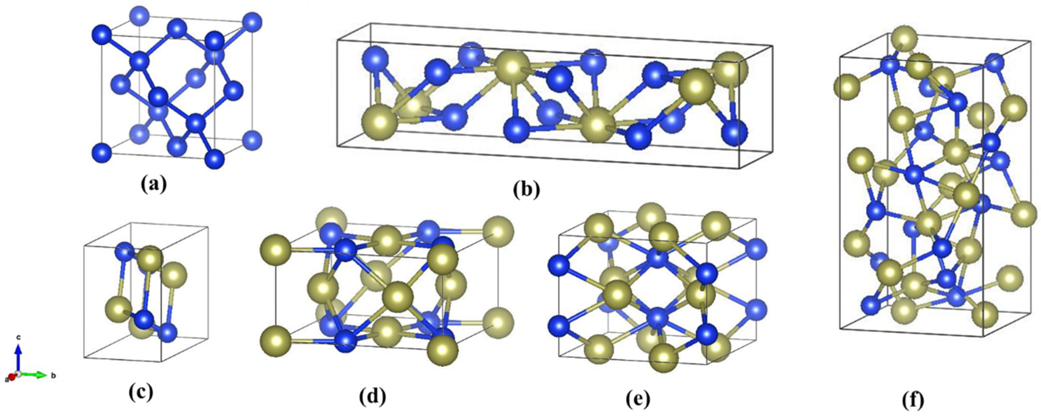
3.1. Structural Properties

Crystal structures of the Hf-Si system are shown in Figure 1, where the calculated material was all a unit cell. For Si, Hf2Si, Hf5Si3, Hf3Si2, Hf5Si4, HfSi, and HfSi2 with Fd3m1, I4/mcm, P63/mcm, P4/mbm, P41212, Pnma, and Cmcm space groups, their structural parameters were optimized, and all lattice parameters and ionic positions were fully relaxed during the geometry optimization. The calculated lattice parameters, along with the corresponding JCPDS card data are presented in Table 1. It can be clearly seen that the calculated parameters of the Hf-Si system were in agreement with the available JCPDS card data. Relative errors of lattice constants of this Hf-Si system are also shown in Figure 2, from which the accuracy of the calculation can be directly observed. The maximum relative error was 1.505% for Hf2Si crystal, and the minimum relative error was only 0.062%. This further explained the accuracy of the calculation results.

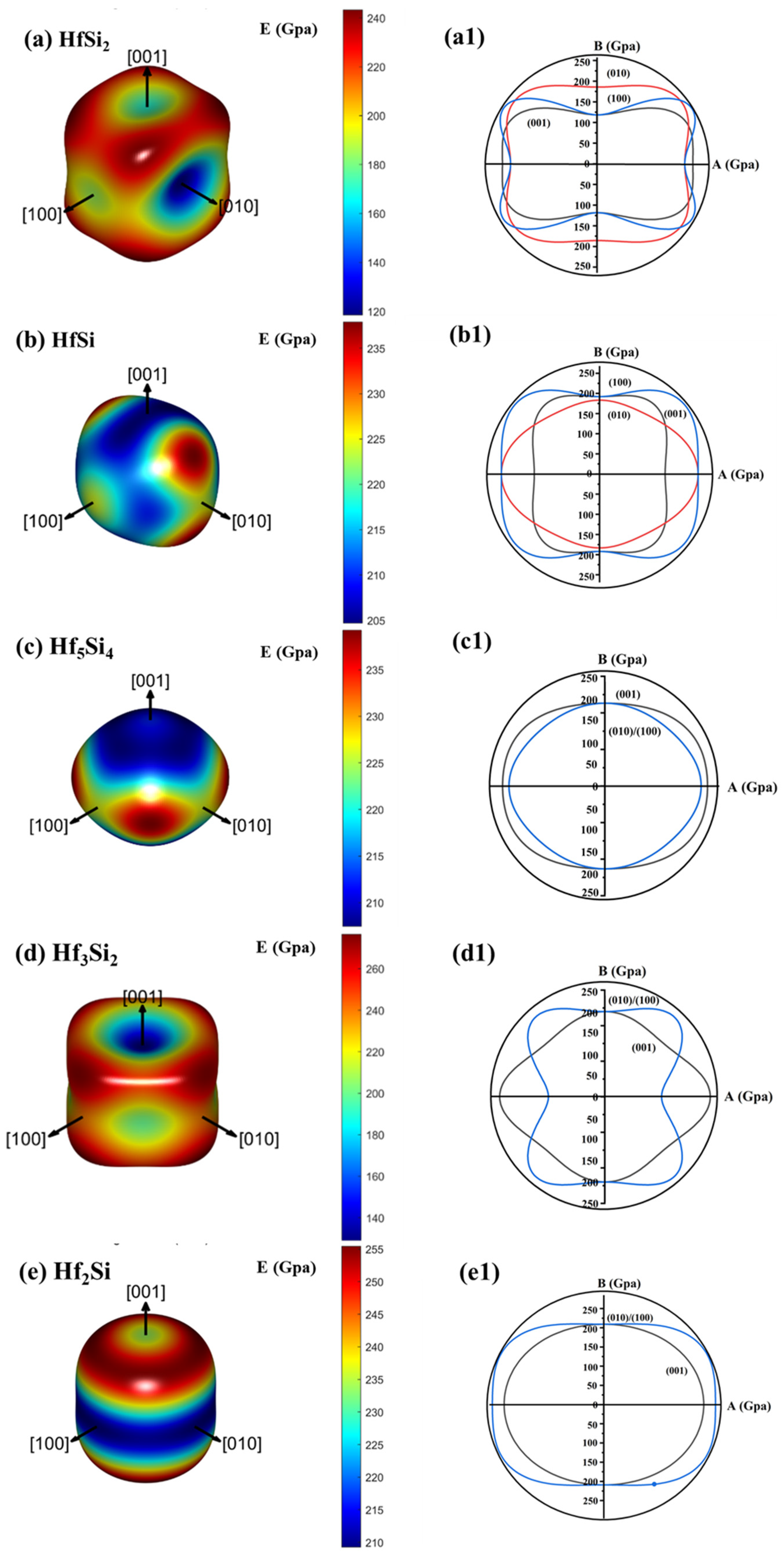
3.2. Elastic and Mechanical Properties

The calculated elastic constants are listed in Table 2. Si is a cubic crystal system with three independent elastic constants, Hf5Si4, Hf3Si2, and Hf2Si, which are tetragonal system with six independent elastic constants, and the rest (HfSi2 and HfSi) are orthomorphic system with nine independent elastic constants. Before further calculation, it is necessary to evaluate whether the above system can resist external deformation and restore its own structure during calculation, namely mechanical stability. The formula suitable for determining the mechanical stability of cubic crystals (Si) [38] is:
C 11 C 12 > 0 , C 11 + 2 C 12 > 0 , C 44 > 0
The requirements of mechanical stability for the Hf-Si system are provided by Born’s conditions for tetragonal (Equation (17)) and orthorhombic (Equation (18)) structures as follows [39,40]:
C 11 C 12 > 0 ,   C 11 + C 33 2 C 13 > 0 ,   C 11 > 0 ,   C 33 > 0 ,   C 44 > 0 , C 66 > 0 ,   2 C 11 + C 33 + 2 C 12 + 4 C 13 > 0
C 11 + C 22 2 C 12 > 0 ,   C 11 + C 33 2 C 13 > 0 ,   C 22 + C 33 2 C 23 > 0 ,   C 11 > 0 , C 22 > 0 , C 33 > 0 , C 44 > 0 , C 55 > 0 , C 66 > 0 , C 11 + C 22 + C 33 + 2 C 12 + 2 C 13 + 2 C 23 > 0
According to the calculated elastic constants of the Si and Hf-Si system, they are all mechanically stable. Therefore, the mechanical properties of the above systems are analyzed below.
The calculated mechanical properties of the Hf-Si system are tabulated in Table 3. First of all, the order of B in the Hf-Si system was HfSi > Hf5Si4 > Hf3Si2 > Hf2Si > HfSi2, and they were much larger than that of Si. Liu et al. once used first principles to calculate the bulk modulus of the Hf-Si system, and found that HfSi had the largest value and HfSi2 had the smallest [41], which is the same as the results in this work. B represents the elasticity of a substance over an elastic range, so among the above materials, HfSi has the strongest incompressible properties. Secondly, G describes a material’s resistance to shape change. The order of G in the Hf-Si system was Hf2Si > HfSi > Hf3Si2 > Hf5Si4 > HfSi2 > Si. For these materials, the G value was obviously smaller than B (Table 3), which had good ductility and machinability. In addition, lower E is preferred as a thermal coating material, because it has good bonding properties and can reduce the influence of thermal stress [42]. Lee et al. calculated the Young’s modulus of Si ‹001› nanowires by using first-principles calculations to be 122.8 GPa [43], which is relatively close to the value calculated here (139 Gpa). This suggests that the calculation result is reliable. The calculated E of Si (139 GPa) was much smaller than that of the Hf-Si system, so Si was better than the Hf-Si system in resistance to thermal stress. In all, the modulus of Si was much smaller than that of the other five materials, which showed that alloying Hf element into Si can increase modulus.
Plasticity is also important for the materials used as EBCs because plastic materials can effectively dissipate thermal stress through plastic deformation. According to the value of Poisson’s ratio, compounds with μ > 0.26 exhibit plasticity [44], which was calculated from Equation (8). Poisson’s ratios of these substances were all smaller than 0.26 as shown in Table 3. This showed that these materials are brittle materials, where the Poisson ratio of Hf5Si4 and HfSi is closer to 0.26 and their plasticity is relatively better. Liu et al. also found that the brittleness of Hf2Si, Hf3Si2, and HfSi2 is obvious, while the brittleness of HfSi and Hf5Si4 is not, preferring ductile materials [41]. It also can be seen that the Hf-Si system has a higher value of Poisson’s ratio than that of Si, and thus improved plasticity. The hardness sequence of the Si and Hf-Si system was Hf2Si > Hf3Si2 > HfSi = HfSi2 > Hf5Si4 > Si at zero temperature and zero pressure. Finally, the G/B values of the Hf-Si system were ordered as Si > Hf2Si > HfSi2 > Hf3Si2 > HfSi > Hf5Si4. A smaller G/B indicates good ductility and damage tolerance, which ensures the integrity of the coating against foreign particles and thermal cycling by avoiding crack formation. In conclusion, these Hf-Si silicides exhibited enhanced plasticity and damage tolerance as compared with Si, which is beneficial to protect SiC composites at high temperatures.
The Young’s modulus, E, describes the resistance of materials against uniaxial tension. To obtain a clear and complete representation of the elastic anisotropy of these materials, the variation of E as a function of crystal orientation is necessary. The direction-dependent E for the Hf-Si system is shown in the following equation [45]:
1 E = l 1 4 + 2 l 1 2 l 2 2 S 12 + 2 l 1 2 l 3 2 S 13 + l 2 4 S 22 + 2 l 2 2 l 3 2 S 23 + l 3 4 S 33 + l 2 2 l 3 2 S 44 + l 1 2 l 3 2 S 55 + l 1 2 l 2 2 S 66
where Sij is the elastic compliance, and then l1, l2, and l3 are the directional cosines of angles with the three principal directions, respectively.
The surface contour of the E of Si is shown in Figure 3a, and the planar projections of E for (100), (010), and (001) crystallographic planes are also shown in Figure 3b. For different crystallographic planes, A and B directions represented different crystallographic directions: A direction represented [100] and B represented [001] for (010) plane, respectively. In the case of the (001) plane, they were [100] and [010] directions; while for (100) plane, they were [001] and [010] directions, respectively [46]. Figure 3a,b clearly illustrates the stereogram of the elastic modulus of Si. Here, it can be seen that the anisotropy of E in the three planes is the same (Figure 3b). In addition, it can be seen that the minimum and maximum E of Si crystal is parallel to <111> and <010> directions, respectively.
The result of surface contour of the E of Hf-Si system and their planar projections of E to (100), (010), and (001) crystallographic planes is shown in Figure 4a–e,a1–e1. For HfSi2 (Figure 4a,a1) and HfSi (Figure 4b,b1), the anisotropy of Young’s modulus on the (100) plane is stronger than that on the other two planes. For Hf5Si4 (Figure 4c,c1), Hf3Si2 (Figure 4d,d1), and Hf2Si (Figure 4e,e1), the anisotropy of (100) and (010) faces was the same. In addition, the minimum Young’s modulus of HfSi2 and Hf2Si is parallel to the (010) direction, and the minimum ones of HfSi, Hf5Si4 and Hf3Si2 are parallel to the (001) direction. Finally, the maximum Young’s modulus of Hf5Si4 is parallel to the (110) direction. The above analysis shows that the anisotropy of the Young’s modulus of the material is closely related to the crystal symmetry. Mohapatra and Eckhardt [47] believe that the anisotropy of the elastic modulus is mainly affected by the non-diagonal elements of the flexibility matrix. When calculating Young’s modulus of different crystallization directions, if the non-diagonal elements (i.e., S12, S13, S23, in this case) are ignored, the degree of anisotropy of the elastic modulus will be significantly reduced. For simplicity, this procedure was not presented here. This confirms that the anisotropy of the Young’s modulus of Si was the lowest among the above substances. Anyway, Figure 3 and Figure 4 showed the anisotropy of the elastic properties of Hf-Si system. Using this information, the most important directions of mechanical property measurements and applications were defined.

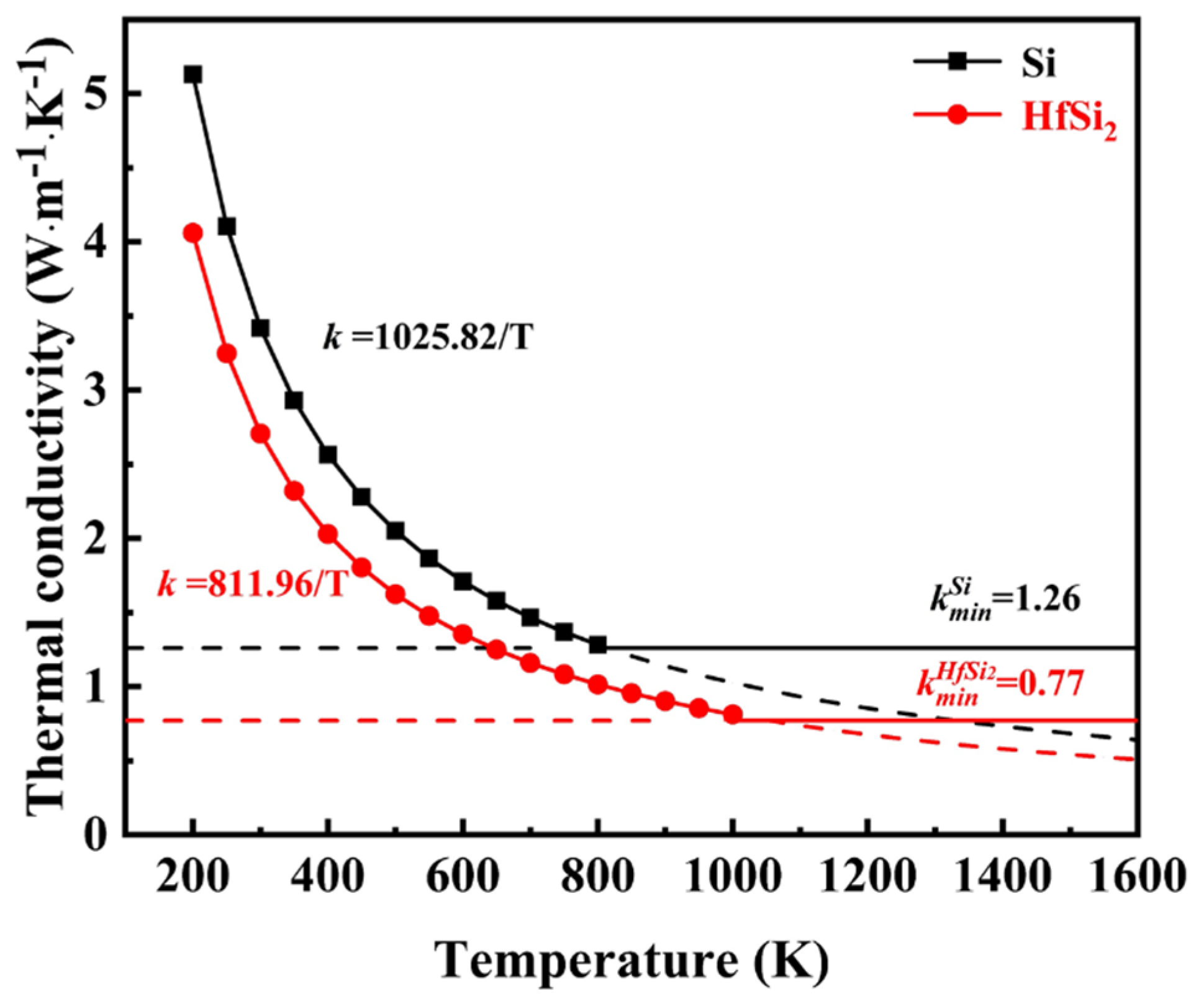
3.3. Thermal Conductivity

The behavior of thermal transportation over different temperature ranges is an important factor to consider when selecting an applicable EBC material. As shown in Equation (15), the estimation of the intrinsic thermal conductivity of Hf-Si system depended on the knowledge of vL, vT, vm and ΘD. According to the calculated elastic moduli and density of the equilibrium structure, the vL, vT, vm and ΘD were derived by Equations (10)–(12). The calculated parameters for Hf-Si system are listed in Table 4. First of all, it shows that the sound velocities of Si (values of vL, vT and vm were 4.42, 2.67 and 2.94 m/s, respectively) are significantly lower than those of the Hf-Si system. In addition, Si also has the highest ΘD (488 K), which is ranked as Si > HfSi2 > HfSi > Hf5Si4 > Hf3Si2 > Hf2Si.
The thermal conductivity includes electron and lattice thermal conductivity. Since the contribution of electrons to the thermal conductivity of semiconductor materials (such as Si and Ge) is relatively small [26], we calculated the lattice thermal conductivity of Hf-Si system here. The intrinsic lattice thermal conductivity k of a material is determined by different phonon scattering mechanisms in different temperature ranges [24]. Firstly, when the temperature is not too high, the main mechanism of phonon scattering is the Umklapp processes, where the acoustic phonon branches interact with each other to transport heat. In this case, Slack’s model [i.e., Equation (14)] [48] is a suitable way to describe the temperature-dependent thermal conductivity. Based on this, the coefficient kp of the Hf-Si system obtained from Equation (13) is listed in Table 5, and Equation (13) can be written as follows:
k = A M ¯ θ D 3 δ γ 2 n 2 3 T = k p T
The lower the kp, the lower the thermal conductivity of the substance at the same temperature. From Table 5, the thermal conductivity of Si (1025.82 W m−1) was much greater than that of Hf-Si system (sorted as Si > HfSi > Hf3Si2 >HfSi2 > Hf2Si> Hf5Si4). Therefore, according to Slack’s model, the Hf-Si system has reduced thermal conductivity than that of Si. In addition, among the Hf-Si system, the E value of HfSi2 is the closest to Si. So for simplicity, taking Si and HfSi2 as examples, their temperature-dependent thermal conductivity estimated from Slack’s model is shown in Figure 5. With the increase in temperature, the thermal conductivity of Si and HfSi2 declined as k = 1025.82/T and k = 811.96/T, respectively. If the temperature is further increased, the phonon mean-free path decreases to the average atomic distance, and thus the thermal conductivity approaches its minimum [24].
Slack’s model lacks rigorous theories for high-temperature thermal conductivity, so the minimum thermal conductivity kmin is evaluated by the modified Clarke’s model, as illustrated by Equation (15). Compared to the perfect crystal in the calculation, there are inevitable defects in the real Si material. In addition, lattice thermal conductivity was only calculated in this paper, ignoring the contribution of electrons to the thermal conductivity. So, the experimental value of the minimum thermal conductivity of single-crystal Si (2.87 W m−1 K−1) [48] is larger than the calculated value in this paper (1.26 W m−1 K−1). As can be seen in Table 4, the minimum thermal conductivity of the Hf-Si system ordered as Si > HfSi2 > HfSi > Hf5Si4 = Hf3Si2 > Hf2Si, where the thermal conductivity of Hf2Si (0.63 W m−1 K−1) was only half of that of Si (1.26 W m−1 K−1). Clarke found that mixing ions of different atomic masses reduces the minimum thermal conductivity of the system [24]. This explains the decrease in thermal conductivity caused by the incorporation of Hf elements into Si. According to the above, the Hf-Si system could reduce the thermal conductivity and improve the heat insulation ability.

4. Conclusions

In this work, from the first-principles calculations, elastic properties of the Hf-Si system were predicted in a well-approved model. The elastic constants were calculated and the values of the bulk, shear, and Young’s modulus, sound velocities, the Debye temperature and the thermal conductivity coefficient were estimated. The structural parameters of the Hf-Si system obtained by structural optimization were consistent with the existing JCPDS card data. The analysis of the mechanical and thermal properties was as follows:
(1)
The Hf-Si system has improved plasticity and hardness as compared to Si, and reduced G/B value, which benefits in minimizing the thermal stress on the substrate, and increases their thermal shock resistance. In addition, the Young’s modulus of Hf-Si system is higher than that of Si.
(2)
The addition of the Hf element to Si forming silicide can increase the sound velocities and reduce the Debye temperature, and thus reduce the thermal conductivity. Compared with Si, the theoretical minimum thermal conductivity of the Hf-Si system was substantially small, which was only 0.63 W m−1 K−1 for Hf2Si with improved heat insulation ability than that of Si.
(3)
The calculation results show that HfSi2 in the Hf-Si system has the lowest Young’s modulus and good plasticity, making it a good candidate as a bond layer for EBCs used at a high temperature.

Author Contributions

P.H. performed calculation data processing, result analysis, chart design, manuscript drafting and literature sorting. G.H. contributed to the design of the study, the conduct of the study, the interpretation of the results, the revision of the manuscript, and the acquisition of funding. H.L., W.Z. and K.P. reviewed the data and results and refined the manuscript. J.L. was responsible for obtaining funding. W.W. and J.Z. provided the platform. All authors have read and agreed to the published version of the manuscript.

Funding

This work was supported by the National Natural Science Foundation of China (No. 51902183) and the Key Research and Development projects in Shaanxi Province (No. 2018ZDCXL-GY-09-06 and 2021ZDLGY14-06).

Data Availability Statement

Data will be made available on reasonable request.

Conflicts of Interest

Author Jianzhang Li was employed by the company Xi’an Golden Mountain Ceramic Composites Co., Ltd. The remaining authors declare that the research was conducted in the absence of any commercial or financial relationships that could be construed as a potential conflict of interest.

References

  1. Raj, R. Fundamental research in structural ceramics for service near 2000 °C. J. Am. Ceram. Soc. 1993, 76, 2147–2174. [Google Scholar] [CrossRef]
  2. Smialek, J.L.; Robinson, R.C.; Opila, E.J.; Fox, D.S.; Jacobson, N.S. SiC and Si3N4 recession due to SiO2 scale volatility under combustor conditions. Adv. Compos. Mater. 1999, 8, 33–45. [Google Scholar] [CrossRef]
  3. Klemm, H.; Taut, C.; Wötting, G. Long-term stability of nonoxide ceramics in an oxidative environment at 1500 °C. J. Eur. Ceram. Soc. 2003, 23, 619–627. [Google Scholar] [CrossRef]
  4. Lee, K.N.; Fox, D.S.; Bansal, N.P. Rare earth silicate environmental barrier coatings for SiC/SiC composites and Si3N4 ceramics. J. Eur. Ceram. Soc. 2005, 25, 1705–1715. [Google Scholar] [CrossRef]
  5. Tejero-Martin, D.; Bennett, C.; Hussain, T. A review on environmental barrier coatings: History, current state of the art and future developments. J. Eur. Ceram. Soc. 2021, 41, 1747–1768. [Google Scholar] [CrossRef]
  6. Zhang, Z.; Park, Y.; Xue, Z.; Zhang, S.; Byon, E.; Koo, B.-H. Research status of bond coats in environmental barrier coatings. Int. J. Appl. Ceram. Technol. 2022, 19, 1841–1859. [Google Scholar] [CrossRef]
  7. Xiao, S.; Liu, X.; Chang, Z.; Tian, Y.; Zhang, X.; Han, G.; Li, J.; Zhang, J. Si-HfO2 composite powders fabricated by freeze drying for bond layer of environmental barrier coatings. Ceram. Int. 2022, 48, 19266–19273. [Google Scholar] [CrossRef]
  8. Ding, S.; Zeng, Y.; Jiang, D. Oxidation bonding of porous silicon nitride ceramics with high strength and low dielectric constant. Mater. Lett. 2007, 61, 2277–2280. [Google Scholar] [CrossRef]
  9. Kamino, T.; Saka, H. Newly developed high-resolution hot stage and its application to materials science. Microsc. Microanal. Microstruct. 1993, 4, 127–135. [Google Scholar] [CrossRef]
  10. Zhuang, M.A.; Ling, L.; Wei, Z. Environmental Barrier Coating for Aeroengines:Materials and Properties. Adv. Ceram. 2019, 40, 331–344. [Google Scholar]
  11. Sullivan, R.M. Reformulation of Oxide Growth Equations for Oxidation of Silicon Bond Coat in Environmental Barrier Coating Systems. J. Eur. Ceram. Soc. 2019, 39, 5403–5409. [Google Scholar] [CrossRef]
  12. Damby, D.E.; Llewellin, E.W.; Horwell, C.J.; Williamson, B.J.; Najorka, J.; Cressey, G.; Carpenter, M. The α–β phase transition in volcanic cristobalite. J. Appl. Crystallogr. 2014, 47, 1205–1215. [Google Scholar] [CrossRef] [PubMed]
  13. Theil, J.A.; Tsu, D.V.; Watkins, M.W.; Kim, S.S.; Lucovsky, G. Local bonding environments of Si–OH groups in SiO2 deposited by remote plasma-enhanced chemical vapor deposition and incorporated by postdeposition exposure to water vapor. J. Vac. Sci. Technol. A Vac. Surf. Film. 1990, 8, 1374–1381. [Google Scholar] [CrossRef]
  14. Deijkers, J.A.; Wadley, H.N. Hafnium silicate formation during oxidation of a permeable silicon+ HfO2 powder composite system. Acta Mater. 2020, 201, 448–461. [Google Scholar] [CrossRef]
  15. Harder, B.J. Oxidation performance of Si-HfO2 environmental barrier coating bond coats deposited via plasma spray-physical vapor deposition. Surf. Coat. Technol. 2020, 384, 125311. [Google Scholar] [CrossRef]
  16. Yuan, J.; Zhou, X.; Dong, S.; Jiang, J.; Deng, L.; Song, W.; Dingwell, D.B.; Cao, X. Plasma sprayed 18 mol% YO1. 5 stabilized hafnia as potential thermal barrier coating. Ceram. Int. 2021, 47, 14515–14526. [Google Scholar] [CrossRef]
  17. Pi, N.-W.; Zhang, M.; Jiang, J.; Belosludtsev, A.; Vlček, J.; Houška, J.; Meletis, E.I. Microstructure of hard and optically transparent HfO2 films prepared by high-power impulse magnetron sputtering with a pulsed oxygen flow control. Thin Solid Film. 2016, 619, 239–249. [Google Scholar] [CrossRef]
  18. Zhu, D. Development and performance evaluations of HfO2-Si and rare earth-Si based environmental barrier bond coat systems for SiC/SiC ceramic matrix composites. In Proceedings of the International Conference on Metallurgical Coatings and Thin Films, San Diego, CA, USA, 28 April–2 May 2014. [Google Scholar]
  19. Xiao, S.; Li, J.; Liu, X.; Chang, Z.; Huang, P.; Zhang, A.; Tian, Y.; Zhang, X.; Zhang, J.; Han, G. Exploration of the oxidation behavior and doping ratio of the Si–HfO2 bond layer used in environmental barrier coatings. Int. J. Appl. Ceram. Technol. 2023, 20, 1753–1763. [Google Scholar] [CrossRef]
  20. Gigolotti, J.C.J.; Nunes, C.A.; Suzuki, P.A.; Coelho, G.C. Evaluation of Phase Equilibria Involving the Liquid Phase in the Hf-Si System. J. Phase Equilibria Diffus. 2014, 35, 622–630. [Google Scholar] [CrossRef]
  21. Gao, J.; Li, C.; Guo, C.; Du, Z. Thermodynamic re-assessment of the Hf-Si binary system. J. Phys. Conf. Ser. 2018, 1074, 012074. [Google Scholar] [CrossRef]
  22. Kato, Y.; Kakamu, K.; Hironaka, Y.; Arai, N.; Kobayashi, N.; Pierre, G.R.S. Improvement of high-temperature endurance of C/C composites by double coating with SiC and glass materials. J. Chem. Eng. Jpn. 1996, 29, 669–674. [Google Scholar] [CrossRef]
  23. Engström, I.; Lönnberg, B. Thermal expansion studies of the group IV-VII transition-metal disilicides. J. Appl. Phys. 1988, 63, 4476–4484. [Google Scholar] [CrossRef]
  24. Clarke, D.R. Materials selection guidelines for low thermal conductivity thermal barrier coatings. Surf. Coat. Technol. 2003, 163, 67–74. [Google Scholar] [CrossRef]
  25. Liu, B.; Wang, J.; Li, F.; Zhou, Y. Theoretical elastic stiffness, structural stability and thermal conductivity of La2T2O7 (T=Ge, Ti, Sn, Zr, Hf) pyrochlore. Acta Mater. 2010, 58, 4369–4377. [Google Scholar] [CrossRef]
  26. Slack, G.A. Nonmetallic crystals with high thermal conductivity. J. Phys. Chem. Solids 1973, 34, 321–335. [Google Scholar] [CrossRef]
  27. Kresse, G.; Joubert, D. From ultrasoft pseudopotentials to the projector augmented-wave method. Phys. Rev. B 1999, 59, 1758–1775. [Google Scholar] [CrossRef]
  28. Blöchl, P.E. Projector augmented-wave method. Phys. Rev. B 1994, 50, 17953–17979. [Google Scholar] [CrossRef] [PubMed]
  29. Kresse, G.; Furthmüller, J. Efficient Iterative Schemes for Ab Initio Total-Energy Calculations Using a Plane-Wave Basis Set. Phys. Rev. B Condens. Matter 1996, 54, 11169–11186. [Google Scholar] [CrossRef] [PubMed]
  30. Hill, R. The elastic behavior of crystalline aggregate. Proc. Phys. Society. Sect. A 1952, 65, 349–354. [Google Scholar] [CrossRef]
  31. Voigt, W. Lehrbuch der Kristallphysik; Teubner-Leipzig: Macmillan, NY, USA, 1928. [Google Scholar]
  32. Reuss, A. Calculation of the flow limits of mixed crystals on the basis of the plasticity of monocrystals. Z. Angew. Math. Mech 1929, 9, 49–58. [Google Scholar] [CrossRef]
  33. Nye, J.F. Physical Properties of Crystals: Their Representation by Tensors and Matrices; Oxford University Press: Oxford, UK, 1985. [Google Scholar]
  34. Green, D.J. An Introduction to the Mechanical Properties of Ceramics; Cambridge University Press: Cambridge, UK, 1998; Volume 1, pp. 1–12. [Google Scholar]
  35. Nazipov, D.V. First-Principles Study of Elastic Properties of Rare-Earth Oxyorthosilicates R2SiO5. Phys. Status Solidi (B) 2021, 258, 2100181. [Google Scholar] [CrossRef]
  36. Anderson, O.L. A simplified method for calculating the debye temperature from elastic constants. J. Phys. Chem. Solids 1963, 24, 909–917. [Google Scholar] [CrossRef]
  37. Sanditov, B.D.; Tsydypov, S.B.; Sanditov, D.S. Relation between the Grüneisen constant and Poisson’s ratio of vitreous systems. Acoust. Phys. 2007, 53, 594–597. [Google Scholar] [CrossRef]
  38. Wang, J.; Li, J.; Yip, S.; Phillpot, S.; Wolf, D. Mechanical instabilities of homogeneous crystals. Phys. Rev. B 1995, 52, 12627–12635. [Google Scholar] [CrossRef] [PubMed]
  39. Beckstein, O.; Klepeis, J.E.; Hart, G.; Pankratov, O. First-principles elastic constants and electronic structure of α-Pt2Si and PtSi. Phys. Rev. B 2001, 13, 134112. [Google Scholar] [CrossRef]
  40. Wu, Z.J.; Zhao, E.J.; Xiang, H.P.; Hao, X.F.; Liu, X.J.; Meng, J. Crystal structures and elastic properties of superhard IrN2 and IrN3 from first principles. Phys. Rev. 2007, 76, 054115. [Google Scholar]
  41. Liu, Q.-J.; Tian, H.; Liu, Z.-T. Mechanical properties and electronic structures of the Hf–Si system: First-principles calculations. Solid State Commun. 2015, 205, 39–45. [Google Scholar] [CrossRef]
  42. Makishima, A.; Mackenzie, J.D. Calculation of bulk modulus, shear modulus and Poisson’s ratio of glass. J. Non-Cryst. Solids 1975, 17, 147–157. [Google Scholar] [CrossRef]
  43. Lee, B.; Rudd, R.E. First-principles calculation of mechanical properties of Si⟨001⟩ nanowires and comparison to nanomechanical theory. Phys. Rev. B 2007, 75, 195328. [Google Scholar] [CrossRef]
  44. Mattesini, M.; Magnuson, M.; Tasnadi, F.; Höglund, C.; Abrikosov, I.A.; Hultman, L. Elastic properties and electrostructural correlations in ternary scandium-based cubic inverse perovskites: A first-principles study. Phys. Rev. B 2009, 79, 125122. [Google Scholar] [CrossRef]
  45. Robertson, J.H. Physical properties of crystals: Their representation by tensors and matrices by J. F. Nye. Acta Crystallogr. 2014, 41, 624. [Google Scholar] [CrossRef]
  46. Brantley, W.A. Calculated Elastic Constants for Stress Problems Associated with Semiconductor Devices. J. Appl. Phys. 1973, 44, 534–535. [Google Scholar] [CrossRef]
  47. Mohapatra, H.; Eckhardt, C.J. Elastic constants and related mechanical properties of the monoclinic polymorph of the carbamazepine molecular crystal. J. Phys. Chem. B 2008, 112, 2293–2298. [Google Scholar] [CrossRef] [PubMed]
  48. Shanks, H.; Maycock, P.; Sidles, P.; Danielson, G. Thermal conductivity of silicon from 300 to 1400 K. Phys. Rev. 1963, 130, 1743. [Google Scholar] [CrossRef]
Figure 1. Crystal structures of the Hf-Si system: (a) Si, (b) HfSi2, (c) HfSi, (d) Hf3Si2, (e) Hf2Si, (f) Hf5Si4 (the blue represented Si atoms and the brown represented Hf atoms).
Jcs 08 00129 g001
Figure 2. Relative errors of lattice constants of the Hf-Si system.
Jcs 08 00129 g002
Figure 3. (a) Surface contour of direction-dependent Young’s modulus of Si and (b) its planar projections on (100), (010), and (001) crystallographic planes.
Jcs 08 00129 g003
Figure 4. Surface contour of direction-dependent Young’s modulus of (a) HfSi2, (b) HfSi, (c) Hf5Si4, (d) Hf3Si2, (e) Hf2Si and (a1e1) planar projections on (100), (010), and (001) crystallographic planes.
Jcs 08 00129 g004
Figure 5. Temperature dependence of thermal conductivity of Si and HfSi2. The minimum thermal conductivity (dash line) was also shown.
Jcs 08 00129 g005
Table 1. The equilibrium lattice parameters (Å) of the Hf-Si system compared with the JCPDS card data.
Materialsa ( A ˙ )b ( A ˙ )c ( A ˙ )
Si5.4505.4505.450
Si (27-1402)5.4315.4315.431
HfSi23.65614.6403.670
HfSi2 (38-1373)3.68014.5563.649
HfSi6.8963.7885.249
HfSi (13-0369)6.8853.7535.191
Hf5Si47.0677.06712.877
Hf5Si4 (42-1166)7.0397.03912.869
Hf3Si27.0147.0143.681
Hf3Si2 (14-0427)7.0007.0003.671
Hf2Si6.5796.5795.180
Hf2Si (12-0467)6.4806.4805.210
Table 2. Calculated independent second-order elastic constants Cij (in GPa) for the Hf-Si system.
MaterialsC11C12C13C22C23C33C44 C 55 C66
Si13852 69
HfSi2237571131569725811192104
HfSi23810983250863161398192
Hf5Si42729188 2559981
Hf3Si229462100 18584117
Hf2Si2508680 27283114
Table 3. Calculated bulk modulus B (GPa), shear modulus G (GPa), Young’s modulus E (GPa), Poisson’s ratio (μ), and Hardness (H) of Hf-Si system.
MaterialsB (GPa)G (GPa)E (GPa)μH (HV)G/B
Si80571390.213110.722
HfSi2125832040.229130.664
HfSi150942340.241130.627
Hf5Si4148882190.253120.595
Hf3Si2142932290.231140.655
Hf2Si140962350.221150.686
Table 4. Sound velocities (vL, vT, vm, in km s−1), Debye temperature ΘD (in K), and minimum thermal conductivity kmin (in W m−1 K−1) of Hf-Si system.
MaterialsvL (m/s)vT (m/s)vm (m/s)ΘD (K)kmin (w/(m·k))
Si4.422.672.944881.26
HfSi25.423.213.564180.77
HfSi5.213.053.383910.71
Hf5Si45.022.883.203660.65
Hf3Si24.932.913.233610.65
Hf2Si4.832.893.203590.63
Table 5. The coefficient kp (equivalent to A M ¯ θ D 3 δ γ 2 n 2 3 T ) in Equation (13) of Hf-Si system.
MaterialsSiHfSi2HfSiHf5Si4Hf3Si2Hf2Si
kp1025.82811.96996.11771.05878.01792.10
Disclaimer/Publisher’s Note: The statements, opinions and data contained in all publications are solely those of the individual author(s) and contributor(s) and not of MDPI and/or the editor(s). MDPI and/or the editor(s) disclaim responsibility for any injury to people or property resulting from any ideas, methods, instructions or products referred to in the content.

