Article

Measurement of Magnetic Flux Density Changes in Mode I Interlaminar Fracture in Magnetostrictive Fiber–Embedded Glass Fiber-Reinforced Polymer Composites

1
Department of Frontier Sciences for Advanced Environment, Graduate School of Environmental Studies, Tohoku University, Sendai 980-8579, Japan
2
Department of Materials Processing, Graduate School of Engineering, Tohoku University, Sendai 980-8579, Japan
*
Author to whom correspondence should be addressed.
J. Compos. Sci. 2024, 8(1), 8; https://doi.org/10.3390/jcs8010008
Submission received: 20 October 2023 / Revised: 15 November 2023 / Accepted: 22 December 2023 / Published: 26 December 2023
(This article belongs to the Special Issue Functional Composites: Fabrication and Application)

Abstract

:
As sensor materials for structural health monitoring (SHM, a nondestructive test for the continuous evaluation of the conditions of individual structural components and entire assemblies), magnetostrictive materials, piezoelectric materials, and optical fibers have attracted significant interest. In this study, the mode I interlaminar fracture load and crack self-detection potential of glass fiber-reinforced polymer (GFRP)–embedded magnetostrictive Fe–Co fibers were investigated via double cantilever beam testing. The results indicated that by controlling the amount of Fe–Co fibers introduced into GFRP, the number of Fe–Co fibers could be reduced without compromising the performance of GFRP. Furthermore, the magnetic flux density increased significantly with crack propagation, indicating that the magnetic flux density change could determine crack propagation.

Graphical Abstract

1. Introduction

Composite materials comprising resin and continuous fibers, known as fiber-reinforced polymer (FRP) materials, exhibit numerous advantages over conventional materials [1]. Among them, glass FRP (GFRP) is the most widely utilized, partly because of its relative inexpensiveness. In addition to their strength and light weight, GFRP materials exhibit high shape-freedom degrees, excellent radio wave permeability, thermal and electrical insulation, and corrosion resistance [2,3,4]. Therefore, GFRPs have been employed in a wide range of fields, including aerospace systems, car and ship manufacturing, building construction, and sporting goods manufacturing [5,6,7]. It was recently anticipated that the International Thermonuclear Experimental Reactor and other fusion reactors would use GFRP as an insulating superconducting device [8,9,10]. Additionally, as a laminated material, GFRP is susceptible to internal damage and fractures, such as interlaminar fractures [11,12]. Samborski [13] and Rzeczkowski et al. [14,15,16] experimentally and analytically studied the interlaminar fractures in FRP under three classical loading types (Modes I, II, and III), as well as the combinations of these loading types (the mixed-mode type). Rzeczkowski et al. [16] conducted all of their tests in conjunction with the acoustic emission (AE) signal to precisely detect delamination onset. Mixed-mode is the predominant type of interlaminar fracture in ordinary composite materials. However, it represents a complex fracture that is influenced by multiple parameters. Therefore, it is critical to understand the most basic fracture phenomenon, i.e., Mode I. Compared with the other Modes (II, III, or various mixed modes) that can be employed in the structural design of FRP, Mode I fracture data empirically yield conservative values. In addition to understanding the mechanism of interlaminar fracture, technology is required to clarify the damage state and predict the service life of a material.
Structural health monitoring (SHM) is a type of nondestructive testing (NDT) that provides continuous diagnoses of the conditions of various structure components, as well as entire assemblies [17,18]. Numerous researchers have studied SHM techniques, such as AE [19], the damping ratio [20], and Lamb waves [21]. However, a technology that can apply to all conditions, settings, and applications has not been determined owing to the different advantages, limitations, and ranges of applications, as well as different levels of suitability for each technology [22]. Currently, sensor–embedded composite materials are among the SHM technologies used for imparting composite materials with self-sensing functions. Siwowski et al. [23] evaluated strain-profile characteristics and values using load-bearing tests and finite element analysis (FEA) by embedding glass optical fibers in FRP and employing a Rayleigh dispersion-based dispersive optical fiber sensor technique. Kousiatza et al. [24] applied fiber Bragg gratings to the real-time process monitoring of continuous fiber-reinforced thermoplastic composites. Additionally, the electrical resistance of carbon FRP (CFRP) composites and the damage therein were measured [25]. Wang et al. [26] performed tensile tests on carbon nanofiber/flax FRP laminates and measured their electrical resistance and AE signals to evaluate their strain and damage self-detection properties. To evaluate the crack-sensing ability of CFRP-containing carbon nanotubes and the fractures therein, Takeda and Narita [27] examined their crack propagation-induced electrical resistance change in the polymer interlayer at low temperatures. Piezoelectric material–embedded FRP composites have attracted attention as a real-time SHM technology that does not impact mechanical properties [28].
Regarding self-detection technologies for GFRP, Rodríguez-González and Rubio-González [29] investigated the effects of the weight concentration of graphene nanoplatelets (GNPs) on the mechanical, electrical, thermomechanical, and piezoresistive behaviors of unidirectional GFRP laminates. They observed the strain self-sensing capabilities and internal damage detection during bending tests for beam-type specimens with higher GNP contents. Hassan and Tallman [30] manufactured self-sensing carbon nanofiber–modified GFRP laminates and presented a technique for accurately determining the size and shape of the damage in the self-sensing composites using electrical impedance tomography. They demonstrated that the multiple through-holes and delamination caused by low-velocity impacts can be accurately reconstructed.
Magnetostrictive materials have also attracted attention as SHM technologies [31]. These materials exhibit the Villari effect, in which the surrounding magnetic field changes in response to deformation due to a load; noncontact SHM can be achieved by measuring the magnetic flux density change using a coil or Hall probe [32]. Regarding their advantages, magnetostrictive materials can be used in environments where conductors cannot be directly connected to the structure. Terfenol-D (Tb1−xDyxFe2) is a well-known giant magnetostrictive material. Haile et al. [33] conducted fatigue tests on composite materials with Terfenol-D particles embedded between their graphite–epoxy prepreg layers and evaluated their damage-sensing capability by measuring the magnetic flux density change using a pickup coil. Additionally, other researchers have studied this SHM technology using magnetostrictive FRP composites [34,35,36,37]. Furthermore, Fe–Co alloys exhibit ductility and good workability, and new magnetostrictive epoxy composites have been developed by embedding Fe–Co fibers in epoxy resin [38,39,40]. The magnetostrictive properties of the developed materials were mainly evaluated via compression tests.
However, evaluating the magnetic field distribution around magnetostrictive FRP composites is critical to noncontact measurement, as the magnetostrictive properties and structures of the composite materials must be considered. However, this issue has not been extensively studied, and no conclusions have been drawn. Moreover, the interfacial strength of GFRP–embedded Fe–Co fibers must be determined. The most basic Mode I delamination fracture strength of Fe–Co fibers and FRP must be investigated.
Therefore, in this study, we embedded Fe–Co fibers in GFRP composites and assessed the delamination behavior between Fe–Co fibers and GFRP by changing the number of embedded Fe–Co fibers. We conducted a double cantilever beam (DCB) test to evaluate the fracture load, and the crack self-detection capability of the fabricated composites was discussed. In the DCB test, four Hall probes were placed on the specimen to evaluate the changes in the magnetic field distribution.

Application of Magnetostrictive Composite Materials in Structural Health Monitoring

To safely operate GFRP laminates, the stress applied to the composite structure, as well as its health, must be investigated [41]. Notably, NDT and evaluation (NDT&E) and SHM are well-known evaluation methods. NDT&E allows for the detection, identification, and location of flaws despite being performed over a scheduled interval [41]. Consequently, NDT&E cannot provide detailed information on damage initiation or growth between the inspection intervals. Conversely, the SHM process is aimed at facilitating the continuous detection, location, and quantification of damage in structures [22]. Therefore, the early identification of damage is desirable to ensure the implementation of suitable maintenance procedures to avoid unexpected failures [42]. However, a versatile technique that satisfies all conditions, settings, and applications has not been developed as the existing techniques have their advantages, limitations, and application scopes [22].
Typically, a specific area of the surface of the material is observed using a camera, after which the change in temperature or speckle pattern is evaluated. The methods include an infrared thermography test [43,44], shearography [45,46], and a digital-image correlation test [47]. The advantages include contactless inspection, a simple experimental setup, and high resolution. However, these technologies only apply to surface defects, as their sensitivity decreases with deep defects. Another SHM approach involves attaching a sensor to the surface of the material. A sensor, such as a strain gauge, an acceleration sensor, or an AE sensor, is mounted to the surface, after which the signals obtained from it are measured and evaluated. Although their attachment, maintenance, and replacement are convenient, they require heavy-duty wiring, which can break or cause electromagnetic interference [48]. The material properties are used for SHM, i.e., the variations in the electric resistance and electrostatic capacity of the material comprising the object are measured to evaluate damage or crack propagation [27]. However, the limitation is that the application is restricted to the material of the object, as conductivity is necessary for the measurement of electric resistance. Finally, the modification of the material also represents an SHM approach. Put differently, a novel composite can be fabricated by adding and embedding sensor materials. The sensor materials include optical fibers [49], carbon materials [27], piezoelectric materials [50], and magnetostrictive materials [38]. The sensor embedment chosen for the composite design depends on its application.
Magnetostrictive material–embedded composites have been investigated for the development of novel sensors or energy-harvesting materials utilizing the Villari effect. Yang et al. [39] demonstrated the specific structural design of Fe–Co wire/AlSi composites and their energy-harvesting performance. Kubicka et al. [38,51] reported the preparation and characterization of CFRP embedded with Terfenol-D particles. Furthermore, other researchers have studied magnetostrictive polymer composites for SHM applications [33,52,53].
A pickup coil and a Hall probe were used to measure the Villari effect–induced magnetic field. Regarding a pickup coil, the voltage, Vout, in the coil with an average magnetic flux density vector, B, through the cross-section of the coil can be derived from Faraday’s law as follows:
V o u t = N c A d B d t
where Nc is the number of turns, A is the cross-sectional area of the pickup coil, and t is the time. Therefore, a pickup coil is suitable for measuring the magnetic flux density induced by impact and vibration when the magnetostrictive material is placed inside or near the pickup coil. When a Hall probe is used, the magnetic flux density is measured as the voltage, VHall, and can be obtained using the Lorentz force as follows:
V H a l l = J × B n e e h
where J is the current density vector, ne is the number of electrons per cubic meter, e is the electron, and h is the thickness of the Hall probe. Thereafter, the magnetic field measurement becomes useful for static and dynamic conditions. Magnetic flux density measurements performed using a pickup coil and a Hall probe are not required for direct connection with a magnetostrictive material, as the induced magnetic flux density is distributed in space. In practice, using multiple pickup coils or Hall probes and placing them at appropriate positions, the stress distribution, defects, damage, etc., can be determined based on the difference in the measured values at each point. For example, consider a simply supported GFRP embedded with Fe–Co fibers. The bending load induces magnetic flux density in the air. The bending stress is distributed along the thickness direction, ensuring that normal stress is applied to the Fe–Co fibers according to the laminated position. Thereafter, the Fe–Co fibers are magnetized by the Villari effect. Finally, a magnetic field is induced in the air owing to the magnetized fibers.

2. Materials and Methods

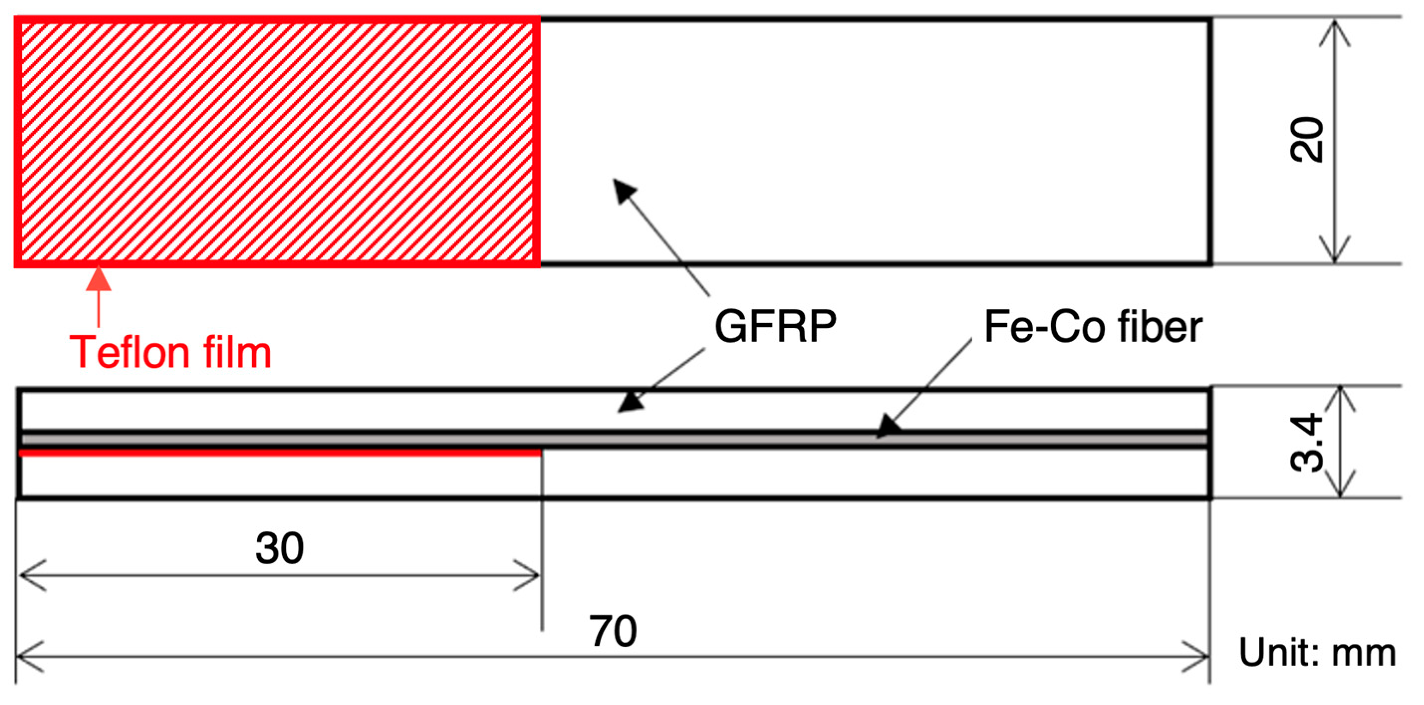
2.1. Material and Specimen Preparation

Prepregs of plain-weave GFRP (EGP-87 LA18BR, SPIC Corporation, Yokohama, Japan), magnetostrictive Fe–Co fibers (K-MP70; diameter, 50 µm; Tohoku Steel Co., Ltd., Miyagi, Japan), and a polytetrafluoroethylene (PTFE) film (965213; thickness, 20 µm; the Nilaco Corporation, Tokyo, Japan) were used to fabricate the specimen. Figure 1 shows a schematic of the specimen. The 10-layer prepregs were stacked on the top and bottom of the layer comprising the Fe–Co fibers. The length direction of the Fe–Co fibers was made parallel to the warp direction of the GFRP prepregs. Four types of specimens were prepared with the following numbers of Fe–Co fibers, n: 0, 40, 60, and 80. Although we had intended to increase the number of fibers by 20, we observed that 20 fibers would be extremely few. Furthermore, it was challenging to fabricate a test specimen with 100 fibers. We placed a PTFE film between the Fe–Co and GFRP layers to allow for a 30 mm precrack, and the length of this precrack was determined by considering the ease of observing crack propagation as well as the effect of jig movement on the magnetic field. After lamination, the specimens were cured in a vacuum (Figure 2a) at 130 °C for 2 h so that no air bubbles were observed in the specimens. After curing, the specimens were cut (length, 70 mm; width, 20; and thickness, 3.4 mm) and polished. The specimen had to be sufficiently small because of the space limitations of the existing electromagnets, as well as the cost of the test. As the specimen enlarged, the magnetic field did not act uniformly on it. Furthermore, two aluminum end blocks (length, 10 mm) were bonded to the precracked end of the specimen (Figure 2b shows an image of the completed specimen).

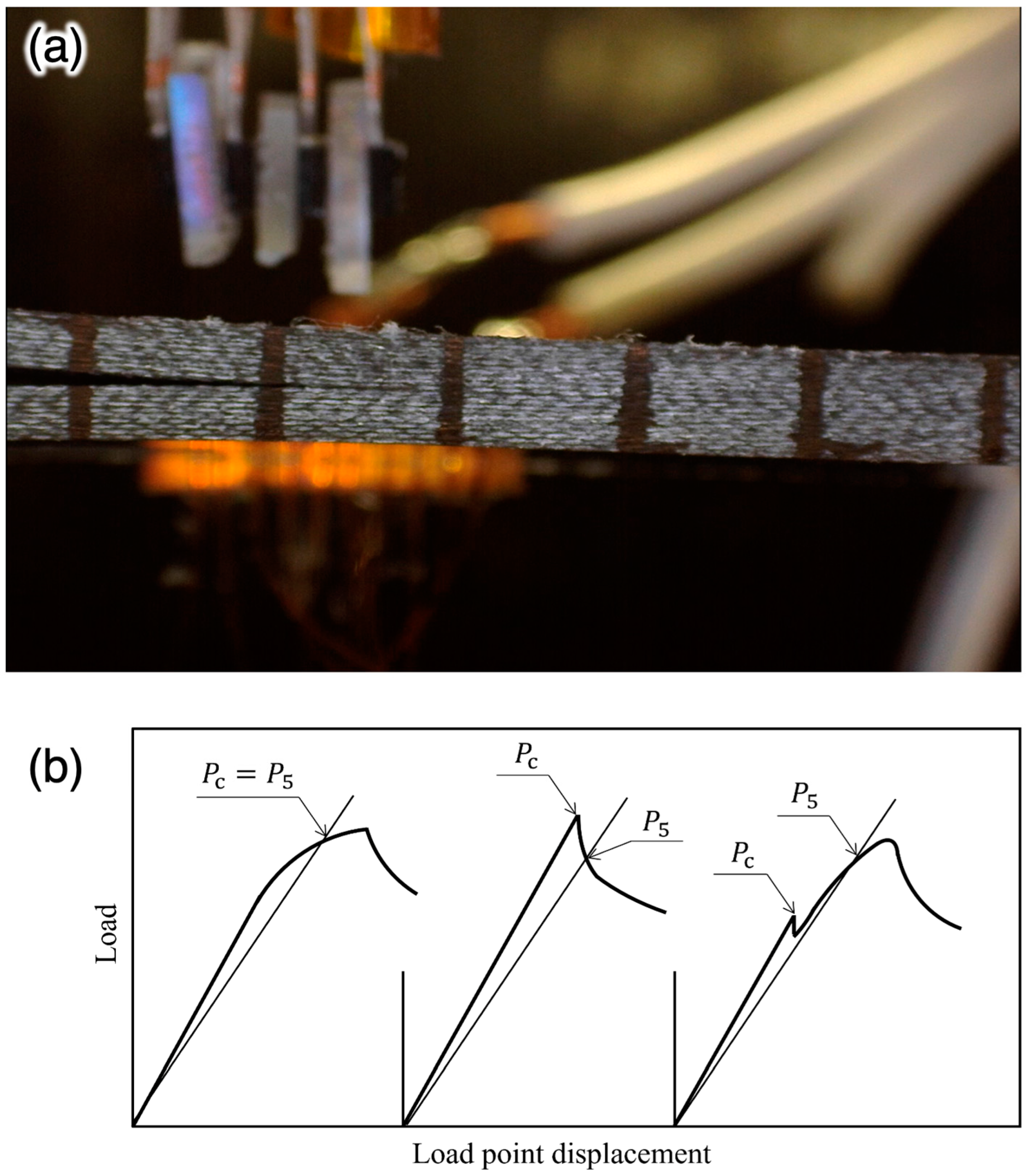
2.2. Mode I Interlaminar Fracture Tests

Round-robin tests of the composite materials for Mode I interlaminar fracture toughness, GIC, have been summarized in [54]. DCB tests were conducted by the participants of the American Society for Testing and Materials (ASTM) Committee D-30 (High Modulus Fibers and their Composites) and representatives of the European Group on Fracture and Japanese Industrial Standards Group. The rate dependence of Mode I interlaminar fracture in the CFRP composite materials was studied over a wide range of loading rates, from quasistatic to impact, at 25 °C [55].
For testing in extreme environments, the interlaminar Mode I fracture behavior of the composite laminates was investigated via DCB testing at high temperatures of 232 °C, 288 °C, and 343 °C [56]. The corrected beam theory and FEA coupled with damage were used at liquid-nitrogen temperature (77 K) and liquid-helium temperature (4 K), and the GIC of the GFRP woven laminates was discussed [57].
The standard method [58,59,60] for measuring GIC was based on the linear elastic fracture mechanics theory, requiring visual measurements of the crack length, thus making data acquisition and analysis challenging. An alternative method for testing the interlaminar fracture toughness was proposed [61] using the elastic–plastic fracture mechanics theory and closed-form analytical solution of the J-integral related to the fracture toughness, JIC.

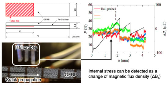
2.3. Damage Test and Magnetic Flux Density Measurement

We conducted DCB tests using the GFRP composite laminates containing the Fe–Co fibers via an autograph (AG-Xplus, Shimadzu Corporation, Kyoto, Japan). Figure 3a shows a schematic of the DCB test. Next, we considered the cartesian coordinate system, O-xyz, where the x-, y-, and z-axes corresponded to the width, thickness, and length directions of the specimen. Four Hall probes (HG-302C; Asahi Kasei Microdevices Corporation, Tokyo, Japan) were placed above the specimen to measure the z-direction change, B z e , in the magnetic flux density. Here, the superscript e denotes the quantity outside the composite. The Hall probe was pre-adjusted to exhibit 0.8 V when the measured magnetic field was 1 mT. The distance between the specimen surface and the center of the Hall probes was 5 mm. Additionally, the distance between the centers of the Hall probes was fixed at 2 mm. Hall probes 1 to 4 were placed starting from the position closest to the precrack tip, with Hall probe 1 placed 2 mm away from the precrack tip. Figure 3b shows the setup for the DCB test. An electromagnet (MAGNIX, Toyo Jiki Industry Co., Ltd., Hyogo, Japan) was used to apply a biased magnetic field of 10 mT. The specifications of the electromagnetic system are as follows: tip ball diameter, 40 mm; pole gap, 90 mm; generated magnetic field, 30 mmT (applied voltage, 3.7 V; current, 5.05 A), and the electromagnet was naturally air-cooled.
A digital microscope (AM4515ZT, AnMo Electronics Corporation, Tokyo, Japan) was used to film the crack propagation. Figure 4a shows a cross-section of the experiment, as captured by the digital microscope. Lines were drawn at 5 mm intervals from the precrack tip to facilitate the measurement of the crack growth. The test was conducted at a speed of 0.5 mm/min, and the test was conducted until the crack propagated more than 20 mm. Analog signals of the load, P, and load-point displacement, u, from the autograph and magnetic flux density change, B z e , from the Hall probe were captured simultaneously by a data logger (NR-500 series, Keyence Corporation, Osaka, Japan). The definition of the initial critical load, P c , is shown in Figure 4b. The intersection of the P–u curve and the straight line with a 5% less angled slope than the initial slope of the P–u curve was taken as P 5 . The maximum or peak value before P 5 was defined as P c .

3. Results and Discussion

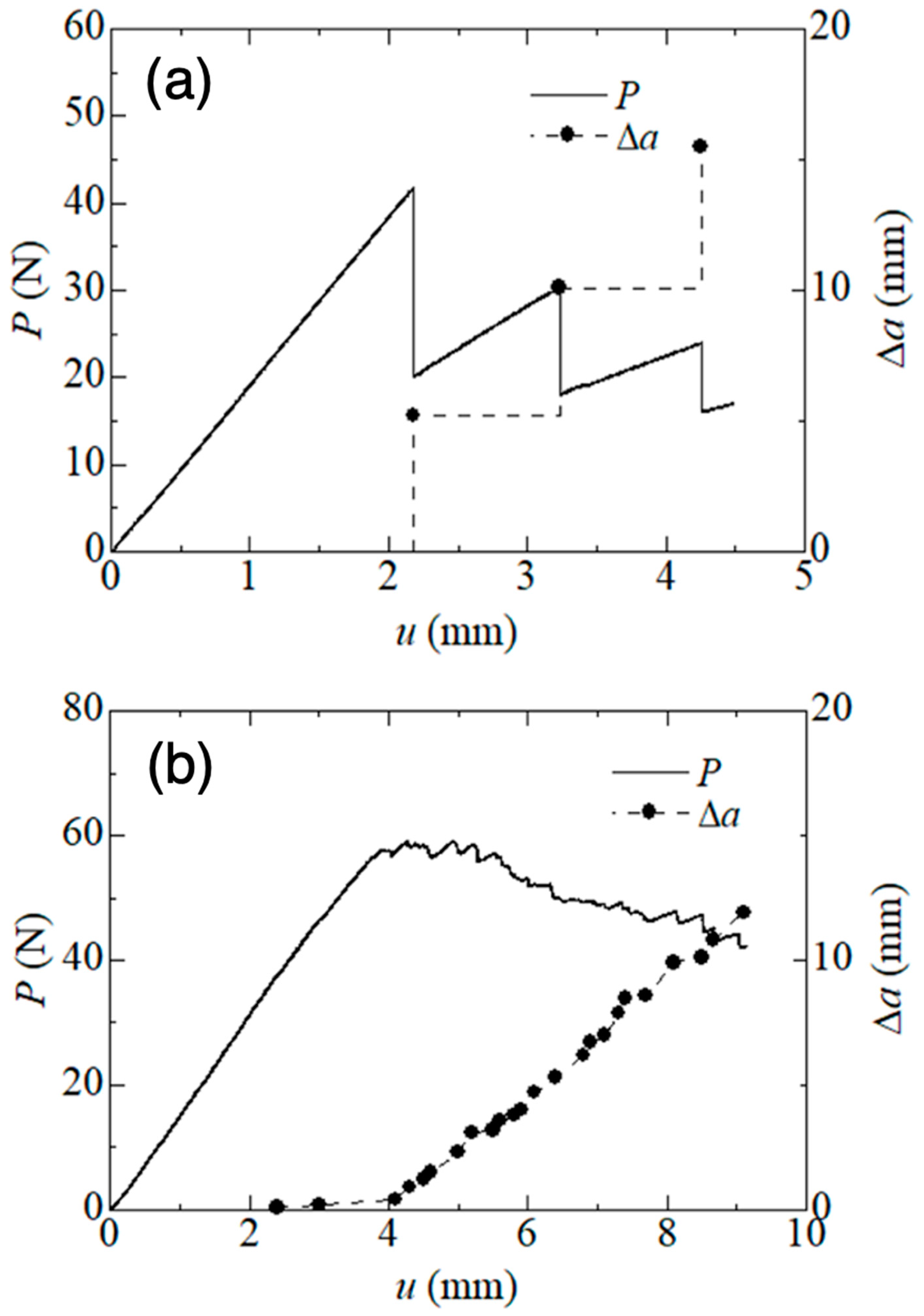
3.1. Fracture Behavior

Figure 5 shows the relationship between the load and load-point displacement of the Fe–Co fibers–embedded GFRP composites. The specimens embedded with 0, 40, 60, and 80 Fe–Co fibers are depicted by black, red, blue, and green lines, respectively. Crack propagation and corresponding load reduction were observed in all the specimens.
Figure 6 shows the load, P, and amount of crack extension, Δa, versus the load-point displacement, u, of each specimen. The solid line represents the load, whereas the dashed line and dots represent the amount of crack extension. Regarding the interface fracture between the Fe–Co fibers and polymer, the load increased almost linearly with the displacement, reaching a peak (Figure 6a). Thereafter, the load decreased rapidly after the crack propagated significantly. After the crack growth stopped, the load increased again, after which it decreased as the crack propagated. This is a specific phenomenon observed in DCB specimens; it is called stick–slip crack propagation. The amount of crack extension was small, and the decrease in the load was small for the interface fracture between the glass fiber and polymer (Figure 6b). In this study, the difference in the interface crack-propagation behavior was mainly attributed to the surface roughness of the fibers. The fiber-drawing process was employed to fabricate the Fe–Co fibers in this study, and their surfaces were covered with numerous scratches. Therefore, when a crack propagates across the interface between the Fe–Co fiber and epoxy resin matrix, it is trapped at a certain point, after which it is released at once, resulting in a staircase-like load–displacement curve (see Figure 6a). Conversely, the surface of glass fibers is smooth as they are melt-spun. Therefore, when the crack propagates at the interface between the glass fiber and epoxy matrix, no trapping is observed at a certain point. The crack propagates continuously after reaching the stress-intensity factor required for crack propagation due to loading, resulting in a linear load–displacement curve (see Figure 6b). Fracture mechanics parameters, such as the stress-intensity factor and energy-release rate, depend on the elastic modulus of the materials on both sides of the interface [62]. At the Fe–Co fiber–polymer interface, the Fe–Co fibers are aligned in parallel. The elastic modulus around the crack tip is almost constant, even after crack propagation. Contrarily, the glass fibers contain warp and weft threads at the glass fiber–polymer interface, and the elastic modulus is locally different in the crack-propagation direction. This difference results in different behavior, as shown in Figure 6.

3.2. Sensor Characterization

In Figure 7, the critical loads of the specimens containing 0, 40, 60, and 80 Fe–Co fibers are compared. We demonstrated that the average value of the critical load decreased as the number of Fe–Co fibers increased, indicating that the specimens tended to fracture more easily. However, as shown by the error bars, the critical load of the specimen containing 40 Fe–Co fibers was sometimes higher than that of the specimen containing 0 Fe–Co fibers. This result indicates the possibility of using the composites containing 40 Fe–Co fibers while maintaining their strength.
Regarding the GFRP composites containing 40 Fe–Co fibers, Figure 8 shows the load and magnetic flux density variation versus the load-point displacement. The load, P, is represented by a solid black line, and the solid red, blue, orange, and green lines represent the magnetic flux density changes, B z e , in Hall probes 1, 2, 3, and 4, respectively. The magnetic flux density decreased or increased as the load decreased with crack propagation. The amounts of crack extension were 1.7, 6.2, and 13.0 mm for load-point displacements of 2.2, 3.0, and 4.1 mm, respectively. The magnetic flux density change decreased during crack propagation before the crack tip passed through the Hall probe; however, it increased as the crack tip passed through or after the Hall probe (see the red line in Hall probe 1). Magnetostrictive materials exhibit a unique phenomenon in which the internal magnetic flux density changes as the load or deformation increases. As the crack propagates, the Fe–Co fibers become more susceptible to deformation, resulting in changes in the magnetic flux density inside the fibers and in the magnetic field around GFRP.
Figure 9 shows the relationship between the amount of magnetic flux density change during crack propagation and the z-direction distance between the crack tip after crack propagation and the positioning of the Hall probe. The red, blue, orange, and green dots represent Hall probes 1, 2, 3, and 4, respectively. A negative horizontal axis indicates the condition before the crack tip passed through the Hall probe, whereas a positive one indicates that the crack tip passed through the Hall probe. The results display a sine curve. Hence, Hall probes can be used to determine the approximate location when a crack initiates and propagates. Put differently, the magnetic flux density change measurement may provide insight into the crack state inside GFRP. To quantitatively understand the state of cracks using the change in magnetic flux density, further experiments and numerical analyses are required, and studies are currently underway.
GFRP is often used at cryogenic temperatures [11], and Fe–Co fibers do not lose their magnetostrictive properties, even at cryogenic temperatures [63], making them a good match for cryogenic applications. In previous studies, fibers with diameters of 1 [39] and 0.2 mm [38] were used, although fibers with a 0.05 mm diameter were used in this study, and they were useful as they did not reduce the GFRP strength. We are currently conducting studies to detect the delamination of GFRP in cryogenic environments.

4. Conclusions

In this study, we fabricated GFRP composites embedded with Fe–Co fibers between the layers of the GFRP laminates and subjected them to DCB tests to verify their interfacial strength and evaluate their crack self-sensing capability. We observed that the load decreased as the crack propagated in all the specimens. The analysis of the fracture surface indicates that some specimens were fractured at the polymer and Fe–Co fiber. Contrarily, others were fractured at the glass fiber–polymer interface. The difference in the fracture was also affected by the crack-propagation method and load change. The critical load decreased as the number of Fe–Co fibers increased. However, when 40 Fe–Co fibers were used, the limit load was sometimes higher than when only GFRP was used, indicating that the Fe–Co fibers could be introduced into GFRP without reducing its strength by reducing the number of introduced Fe–Co fibers. Certainly, the diameter and stiffness of the fibers are also critical, although the focus here is on the number of fibers. Four Hall probes were placed on the specimens containing 40 Fe–Co fibers to monitor the magnetic flux density outside the specimen and evaluate its crack self-detection capability. The magnetic flux density increased or decreased significantly as the crack propagated. We observed a relationship between the change in magnetic flux density when a crack propagated and both the distance between the crack tip and the position of the Hall probe. Hence, it was possible to determine the crack propagation and approximate location of the crack tip from the magnetic flux density change. Accurate crack-state measurement can be achieved with further tests and analyses.

Author Contributions

Conceptualization, K.K.; methodology, K.K.; software, T.M.; validation, T.M. and K.K.; formal analysis, K.K.; investigation, T.M.; resources, T.M. data curation, T.M.; writing—original draft preparation, T.M.; writing—review and editing, K.K., H.K. and F.N.; visualization, T.M. and H.K.; supervision, F.N.; project administration, K.K. and F.N.; funding acquisition, F.N. All authors have read and agreed to the published version of the manuscript.

Funding

This research was supported by a Grant-in-Aid for Scientific Research (A), 22H00183, from the Japan Society for the Promotion of Science.

Data Availability Statement

The materials described in this manuscript, including all relevant raw data, will be made freely available upon reasonable request to the corresponding author for any researcher wishing to use them for non-commercial purposes.

Acknowledgments

The authors acknowledge Tohoku Steel Co., Ltd., for providing the Fe–Co fibers.

Conflicts of Interest

The authors declare no conflicts of interest. The funders and Tohoku Steel Co., Ltd. had no role in the design of the study; in the collection, analyses, or interpretation of the data; in the writing of the manuscript; or in the decision to publish the results.

References

  1. Correia, J.R.; Almeida, N.M.; Figueira, J.R. Recycling of FRP composites: Reusing fine GFRP waste in concrete mixtures. J. Clean. Prod. 2011, 19, 1745–1753. [Google Scholar] [CrossRef]
  2. Zheng, L.; Yue, X.; Yue, L.; Wang, Z.; Xie, Y.; Cui, Z. Electrical/thermal stability of GFRP under different intensities γ ray irradiation. Fusion Eng. Des. 2020, 158, 111856. [Google Scholar] [CrossRef]
  3. Wu, C.; Hwang, H.; Ma, G. Effect of stirrups on the bond behavior of lap spliced GFRP bars in concrete beams. Eng. Struct. 2022, 266, 114552. [Google Scholar] [CrossRef]
  4. Li, S.; Kang, Z.; Wu, G.; Guo, P.; Gu, S. Acoustic emission-based transition monitoring of mechanical mechanism for bolted shear connection in GFRP-UHPC hybrid beams. Measurement 2022, 198, 111358. [Google Scholar] [CrossRef]
  5. El-Tayeb, N.S.; Gadelrab, R.M. Friction and wear properties of E-glass fiber reinforced epoxy composites under different sliding contact conditions. Wear 1996, 192, 112–117. [Google Scholar] [CrossRef]
  6. Tripathi, D.R.; Vachhani, K.H.; Kumari, S.; Dinbandhu, K.; Abhishek, K. Experimental investigation on material removal rate during abrasive water jet machining of GFRP composites. Mater. Today Proc. 2020, 26, 1389–1392. [Google Scholar] [CrossRef]
  7. Wang, Y.; Chen, G.; Wan, B.; Han, B.; Ran, J. Axial compressive behavior and confinement mechanism of circular FRP-steel tubed concrete stub columns. Compos. Struct. 2021, 256, 113082. [Google Scholar] [CrossRef]
  8. Takeda, T.; Shindo, Y.; Narita, F. Three-dimensional thermoelastic analysis of cracked plain weave glass/epoxy composites at cryogenic temperatures. Compos. Sci. Technol. 2004, 64, 2353–2362. [Google Scholar] [CrossRef]
  9. Mitchell, N.; Bauer, P.; Bessette, D.; Devred, A.; Gallix, R.; Jong, C.; Knaster, J.; Libeyre, P.; Lim, B.; Sahu, A.; et al. Status of the ITER magnets. Fusion. Eng. Des. 2009, 84, 113–121. [Google Scholar] [CrossRef]
  10. Mitchell, N.; Devred, A. The ITER magnet system: Configuration and construction status. Fusion. Eng. Des. 2017, 123, 17–25. [Google Scholar] [CrossRef]
  11. Shindo, Y.; Miura, M.; Takeda, T.; Saito, N.; Narita, F. Cryogenic delamination growth in woven glass/epoxy composite laminates under mixed-mode I/II fatigue loading. Compos. Sci. Technol. 2011, 71, 647–652. [Google Scholar] [CrossRef]
  12. Li, N.; Wang, G.D.; Melly, S.K.; Peng, T.; Li, Y.C.; Di Zhao, Q.; de Ji, S. Interlaminar properties of GFRP laminates toughened by CNTs buckypaper interlayer. Compos. Struct. 2019, 208, 13–22. [Google Scholar] [CrossRef]
  13. Samborski, S. Prediction of delamination front’s advancement direction in the CFRP laminates with mechanical couplings subjected to different fracture toughness tests. Compos. Struct. 2018, 202, 643–650. [Google Scholar] [CrossRef]
  14. Rzeczkowski, J.; Samborski, S.; de Moura, M. Experimental investigation of delamination in composite continuous fiber-reinforced plastic laminates with elastic couplings. Materials 2020, 13, 5146. [Google Scholar] [CrossRef] [PubMed]
  15. Rzeczkowski, J.; Paśnik, J.; Samborski, S. Mode III numerical analysis of composite laminates with elastic couplings in split cantilever beam configuration. Compos. Struct. 2021, 265, 113751. [Google Scholar] [CrossRef]
  16. Rzeczkowski, J.; Samborski, S.; Prokopek, K. Experimental determination of the mode I fracture toughness in FRP laminates with hybrid delamination interfaces. Adv. Sci. Technol. Res. J. 2022, 16, 129–135. [Google Scholar] [CrossRef] [PubMed]
  17. Guidorzi, R.; Diversi, R.; Vincenzi, L.; Mazzotti, C.; Simioli, V. Structural monitoring of a tower by means of MEMS-based sensing and enhanced autoregressive models. Eur. J. Control 2014, 20, 4–13. [Google Scholar] [CrossRef]
  18. Pallarés, F.J.; Betti, M.; Bartoli, G.; Pallarés, L. Structural health monitoring (SHM) and nondestructive testing (NDT) of slender masonry structures: A practical review. Constr. Build. Mater. 2021, 297, 123768. [Google Scholar] [CrossRef]
  19. Manterola, J.; Aguirre, M.; Zurbitu, J.; Renart, J.; Turon, A.; Urresti, I. Using acoustic emissions (AE) to monitor mode I crack growth in bonded joints. Eng. Fract. Mech. 2020, 224, 106778. [Google Scholar] [CrossRef]
  20. Shang, Z.; Xia, Y.; Chen, L.; Sun, L. Damping ratio identification using attenuation responses extracted by time series semantic segmentation. Mech. Syst. Signal Process 2022, 180, 109287. [Google Scholar] [CrossRef]
  21. Gorgin, R.; Luo, Y.; Wu, Z. Environmental and operational conditions effects on Lamb wave based structural health monitoring systems: A review. Ultrasonics 2020, 105, 106114. [Google Scholar] [CrossRef] [PubMed]
  22. Amafabia, D.-a.M.; Montalvão, D.; David-West, O.; Haritos, G. A review of structural health monitoring techniques as applied to composite structures. Struct. Health Monit. 2017, 11, 91–147. [Google Scholar]
  23. Siwowski, T.; Rajchel, M.; Howiacki, T.; Sieńko, R.; Bednarski, Ł. Distributed fibre optic sensors in FRP composite bridge monitoring: Validation through proof load tests. Eng. Struct. 2021, 246, 113057. [Google Scholar]
  24. Kousiatza, C.; Tzetzis, D.; Karalekas, D. In-situ characterization of 3D printed continuous fiber reinforced composites: A methodological study using fiber Bragg grating sensors. Compos. Sci. Technol. 2019, 174, 134–141. [Google Scholar] [CrossRef]
  25. Schueler, R.; Joshi, S.P.; Schulte, K. Damage detection in CFRP by electrical conductivity mapping. Compos. Sci. Technol. 2001, 61, 921–930. [Google Scholar] [CrossRef]
  26. Wang, Y.; Chen, G.; Wang, Y.; Han, B.; Wan, B.; Hao, Q.; Bai, Y. Tensile strain and damage self-sensing of flax FRP laminates using carbon nanofiber conductive network coupled with acoustic emission. Compos. Struct. 2022, 290, 115549. [Google Scholar] [CrossRef]
  27. Takeda, T.; Narita, F. Fracture behavior and crack sensing capability of bonded carbon fiber composite joints with carbon nanotube-based polymer adhesive layer under mode I loading. Compos. Sci. Technol. 2017, 146, 26–33. [Google Scholar] [CrossRef]
  28. Kozioł, M.; Toroń, B.; Szperlich, P.; Jesionek, M. Fabrication of a piezoelectric strain sensor based on SbSI nanowires as a structural element of a FRP laminate. Compos. B Eng. 2019, 157, 58–65. [Google Scholar] [CrossRef]
  29. Rodríguez-González, J.A.; Rubio-González, C. Influence of graphene nanoplatelet concentration on the electrical, mechanical, and piezoresistive properties of glass fiber/epoxy composites. Poly Compos. 2022, 43, 3276–3289. [Google Scholar] [CrossRef]
  30. Hassan, H.; Tallman, T.N. Precise damage shaping in self-sensing composites using electrical impedance tomography and genetic algorithms. Struct. Health Monit. 2023, 22, 372–387. [Google Scholar] [CrossRef]
  31. He, Z.; Li, W.; Salehi, H.; Zhang, H.; Zhou, H.; Jiao, P. Integrated structural health monitoring in bridge engineering. Autom. Constr. 2022, 136, 104168. [Google Scholar] [CrossRef]
  32. Kwun, H.; Bartels, K.A. Magnetostrictive sensor technology and its applications. Ultrasonics 1998, 36, 171–178. [Google Scholar] [CrossRef]
  33. Haile, M.A.; Hall, A.J.; Yoo, J.H.; Coatney, M.D.; Myers, O.J. Detection of damage precursors with embedded magnetostrictive particles. J. Intell. Mater. Syst. Struct. 2016, 27, 1567–1576. [Google Scholar] [CrossRef]
  34. Kubicka, M.; Mahrholz, T.; Kühn, A.; Wierach, P.; Sinapius, M. Magnetostrictive properties of epoxy resins modified with Terfenol-D particles for detection of internal stress in CFRP. Part 1: Materials and processes. J. Mater. Sci. 2012, 47, 5752–5759. [Google Scholar] [CrossRef]
  35. Norhaniza, R.; Mazlan, S.A.; Ubaidillah, S.A.; Abdul Aziz, S.A.A.; Nazmi, N.; Yunus, N.A. Enhancement of sensitivity of magnetostrictive foam in low magnetic fields for sensor applications. Polymer 2020, 211, 123083. [Google Scholar] [CrossRef]
  36. Surakarnkha, J.; Zhaoyuan, L.; Gong, P.; Holmes, W.; Desai, P.; Foreman, J.; Morley, N. Designing ferrite impregnated epoxy actuators for impact damage detection in carbon fibre reinforced composites. Compos. Sci. Technol. 2021, 216, 109085. [Google Scholar] [CrossRef]
  37. Peng, J.; Zhang, S.; Jia, S.; Kang, X.; Yu, H.; Yang, S.; Wang, S.; Yang, Y. A highly sensitive magnetic field sensor based on FBG and magnetostrictive composite with oriented magnetic domains. Measurement 2022, 189, 110667. [Google Scholar] [CrossRef]
  38. Narita, F.; Katabira, K. Stress-rate dependent output voltage for Fe29Co71 magnetostrictive fiber/polymer composites: Fabrication, experimental observation and theoretical prediction. Mater. Trans. 2017, 58, 302–304. [Google Scholar] [CrossRef]
  39. Yang, Z.; Wang, Z.; Seino, M.; Kumaoka, D.; Murasawa, G.; Narita, F. Twisting and reverse magnetic field effects on energy conversion of magnetostrictive wire metal matrix composites. Phys. Rapid Res. Lett. 2020, 14, 2000281. [Google Scholar]
  40. Yang, Z.; Wang, Z.; Nakajima, K.; Neyama, D.; Narita, F. Structural design and performance evaluation of FeCo/epoxy magnetostrictive composites. Compos. Sci. Technol. 2021, 210, 108840. [Google Scholar] [CrossRef]
  41. Ahmed, O.; Wang, X.; Tran, M.V.; Ismadi, M.Z. Advancements in fiber-reinforced polymer composite materials damage detection methods: Towards achieving energy-efficient SHM systems. Compos. B Eng. 2021, 223, 109136. [Google Scholar]
  42. Hassani, S.; Mousavi, M.; Gandomi, A.H. Structural health monitoring in composite structures: A comprehensive review. Sensors 2021, 22, 153. [Google Scholar] [CrossRef] [PubMed]
  43. Wang, M.; Gao, B.; Wu, T.; Hu, B.; Liu, L. Defect depth retrieval method based on nonlinear transformation for pulsed thermographic inspection. Int. J. Therm. Sci. 2020, 149, 106196. [Google Scholar] [CrossRef]
  44. Wang, Z.; Zhu, J.; Tian, G.Y.; Ciampa, F. Comparative analysis of eddy current pulsed thermography and long pulse thermography for damage detection in metals and composites. Ndt E Int. 2019, 107, 102155. [Google Scholar] [CrossRef]
  45. Gholizadeh, S. A review of non-destructive testing methods of composite materials. Procedia Struct. Integr. 2016, 1, 50–57. [Google Scholar] [CrossRef]
  46. Hung, Y.Y. Digital shearography versus TV-holography for non-destructive evaluation. Opt. Lasers Eng. 1997, 26, 421–436. [Google Scholar] [CrossRef]
  47. Orell, O.; Vuorinen, J.; Jokinen, J.; Kettunen, H.; Hytönen, P.; Turunen, J.; Kanerva, M. Characterization of elastic constants of anisotropic composites in compression using digital image correlation. Compos. Struct. 2018, 185, 176–185. [Google Scholar] [CrossRef]
  48. Janeliukstis, R.; Mironovs, D. Smart composite structures with embedded sensors for load and damage monitoring—A review. Mech. Compos. Mater. 2021, 57, 131–152. [Google Scholar] [CrossRef]
  49. Sánchez, D.M.; Gresil, M.; Soutis, C. Distributed internal strain measurement during composite manufacturing using optical fibre sensors. Compos. Sci. Technol. 2015, 120, 49–57. [Google Scholar] [CrossRef]
  50. Wang, Z.; Kurita, H.; Nagaoka, H.; Narita, F. Potassium sodium niobate lead-free piezoelectric nanocomposite generators based on carbon-fiber-reinforced polymer electrodes for energy-harvesting structures. Compos. Sci. Technol. 2020, 199, 108331. [Google Scholar] [CrossRef]
  51. Kubicka, M.; Mahrholz, T.; Kühn, A.; Wierach, P.; Sinapius, M. Magnetostrictive properties of epoxy resins modified with Terfenol-D particles for detection of internal stress in CFRP. Part 2: Evaluation of stress detection. J. Mater. Sci. 2013, 48, 6578–6584. [Google Scholar] [CrossRef]
  52. Adelsberg, N.; Weber, Y.; Yoffe, A.; Shilo, D. Wireless thin layer force sensor based on a magnetostrictive composite material. Smart Mater. Struct. 2017, 26, 065013. [Google Scholar] [CrossRef]
  53. Na, S.M.; Park, J.J.; Jones, N.J.; Werely, N.; Flatau, A.B. Magnetostrictive whisker sensor application of carbon fiber-Alfenol composites. Smart Mater. Struct. 2018, 27, 105010. [Google Scholar] [CrossRef]
  54. O’Brien, T.K.; Martin, R.H. Round robin testing for mode I interlaminar fracture toughness of composite materials. J. Compos. Technol. Res. 1993, 15, 269–281. [Google Scholar]
  55. Kusaka, T.; Hojo, M.; Mai, Y.W.; Kurokawa, T.; Nojima, T.; Ochiai, S. Rate dependence of mode I fracture behaviour in carbon-fibre/epoxy composite laminates. Compos. Sci. Technol. 1998, 58, 591–602. [Google Scholar] [CrossRef]
  56. Wang, W.X.; Takao, Y.; Yuan, F.G.; Potter, B.D.; Pater, R.H. The interlaminar mode I fracture of IM7/LaRC-RP46 composites at high temperatures. J. Compos. Mater. 1998, 32, 1508–1526. [Google Scholar] [CrossRef]
  57. Sumikawa, M.; Shindo, Y.; Takeda, T.; Narita, F.; Takano, S.; Sanada, K. Analysis of mode I interlaminar fracture and damage behavior of GFRP woven laminates at cryogenic temperatures. J. Compos. Mater. 2005, 39, 2053–2066. [Google Scholar] [CrossRef]
  58. K7086-1993; Testing Methods for Interlaminar Fracture Toughness of Carbon Fibre Reinforced Plastics. Japanese Industrial Standard: Tokyo, Japan, 1993. Available online: https://kikakurui.com/k7/K7086-1993-01.html (accessed on 31 October 2023).
  59. ASTM D5528-13; Standard Test Method for Mode-I Interlaminar Fracture Toughness of Unidirectional Fiber Reinforced Polymer Matrix Composite. ASTM: West Conshohocken, PA, USA, 2022. Available online: https://www.astm.org/d5528-13.html (accessed on 31 October 2023).
  60. ISO 15024; Fibre-Reinforced Plastic Composites—Determination of Mode I Interlaminar Fracture Toughness, GIC, for Unidirectionally Reinforced Materials. ISO: Geneva, Switzerland, 2001. Available online: https://www.iso.org/standard/25581.html (accessed on 31 October 2023).
  61. Gunderson, J.D.; Brueck, J.F.; Paris, A.J. Alternative test method for interlaminar fracture toughness of composites. Int. J. Fract. 2007, 143, 273–276. [Google Scholar] [CrossRef]
  62. Barut, A.; Guven, I.; Madenci, E. Analysis of singular stress fields at junctions of multiple dissimilar materials under mechanical and thermal loading. Int. J. Solids Struct. 2001, 38, 9077–9109. [Google Scholar] [CrossRef]
  63. Katabira, K.; Komagome, R.; Narita, F. Novel process for monitoring stress in carbon fiber reinforced polymer composites using magnetostrictive wires from cryogenic to high temperatures. Mech. Adv. Mater. Struct. 2022, 1–9, in press. [Google Scholar] [CrossRef]
Figure 1. Schematic illustration and dimensions of the double cantilever beam (DCB) specimen.
Jcs 08 00008 g001
Figure 2. Appearances of the specimen (a) during the vacuum treatment and (b) after curing with jigs.
Jcs 08 00008 g002
Figure 3. (a) Schematic and (b) implementation pictures of the DCB test: 4 Hall probes were positioned at the center of the specimen. The crack propagation passed under these Hall probes. The electromagnets applied a magnetic field bias, and the crack propagation was monitored under a digital microscope.
Jcs 08 00008 g003
Figure 4. (a) Exhibition of crack propagation during the DCB test and (b) determination rules of the initial critical load for three typical crack-propagation behaviors based on the relationship between Pc and P5.
Jcs 08 00008 g004
Figure 5. Load–displacement curves of the GFRP specimens containing 0, 40, 60, and 80 Fe–Co fibers.
Jcs 08 00008 g005
Figure 6. Load–displacement curves when the GFRP specimens were fractured at the (a) Fe–Co fiber–polymer and (b) glass fiber–polymer interfaces.
Jcs 08 00008 g006
Figure 7. Critical loads versus the number of Fe–Co fibers.
Jcs 08 00008 g007
Figure 8. Comparison of the magnetic flux density changes at each Hall probe and load–displacement curve (black line).
Jcs 08 00008 g008
Figure 9. Magnetic flux density changes versus the distance in the z-direction between the crack tip and probe position.
Jcs 08 00008 g009
Disclaimer/Publisher’s Note: The statements, opinions and data contained in all publications are solely those of the individual author(s) and contributor(s) and not of MDPI and/or the editor(s). MDPI and/or the editor(s) disclaim responsibility for any injury to people or property resulting from any ideas, methods, instructions or products referred to in the content.

