

Friction Stir Spot Welding of Thin Aluminium Sheets to Polyamide 6: A Study of the Welding Parameters and Strategies
 ,
,  , ,
, ,  and
and 
Abstract
1. Introduction
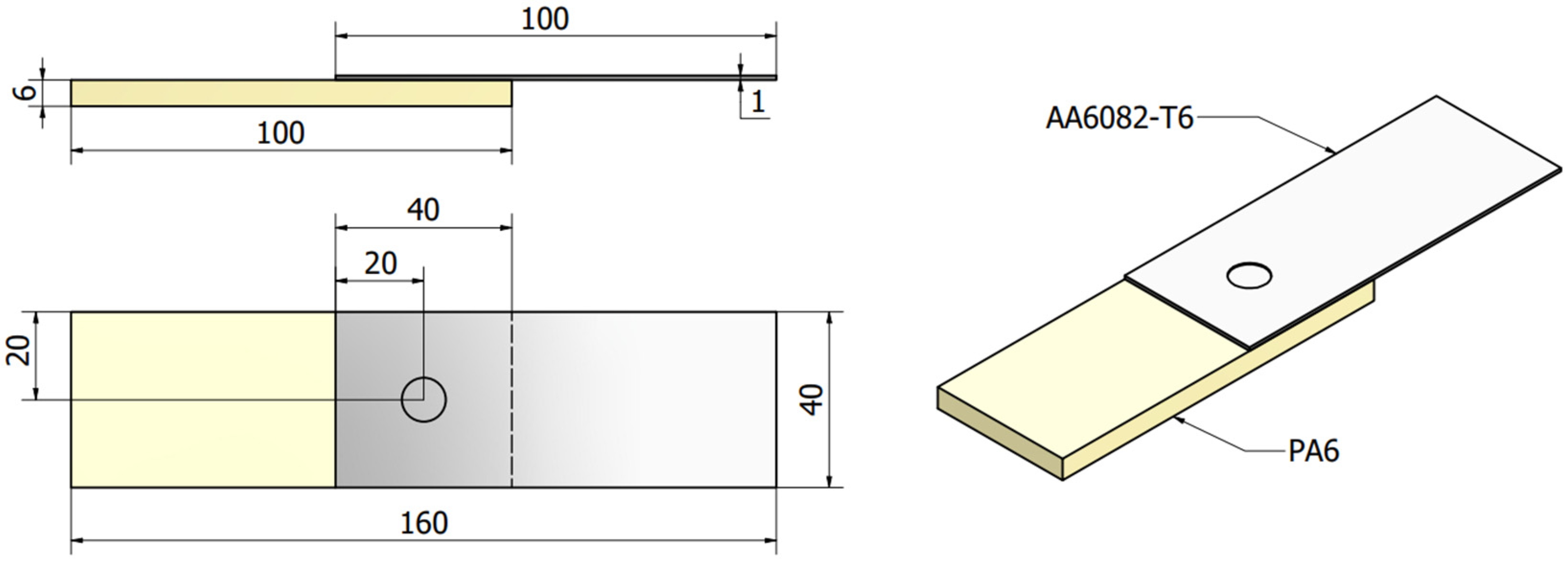
2. Materials and Methods
3. Results
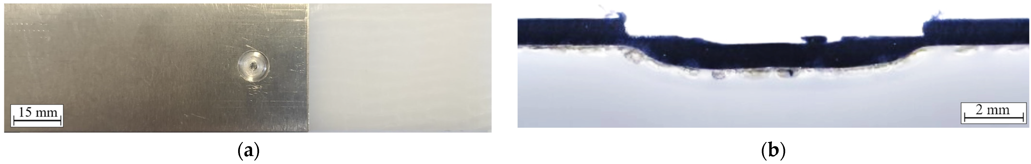
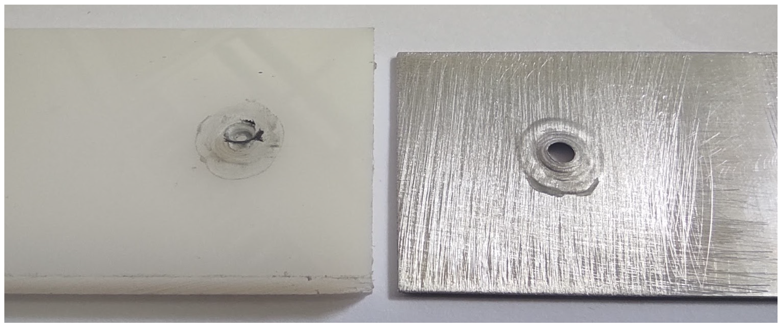
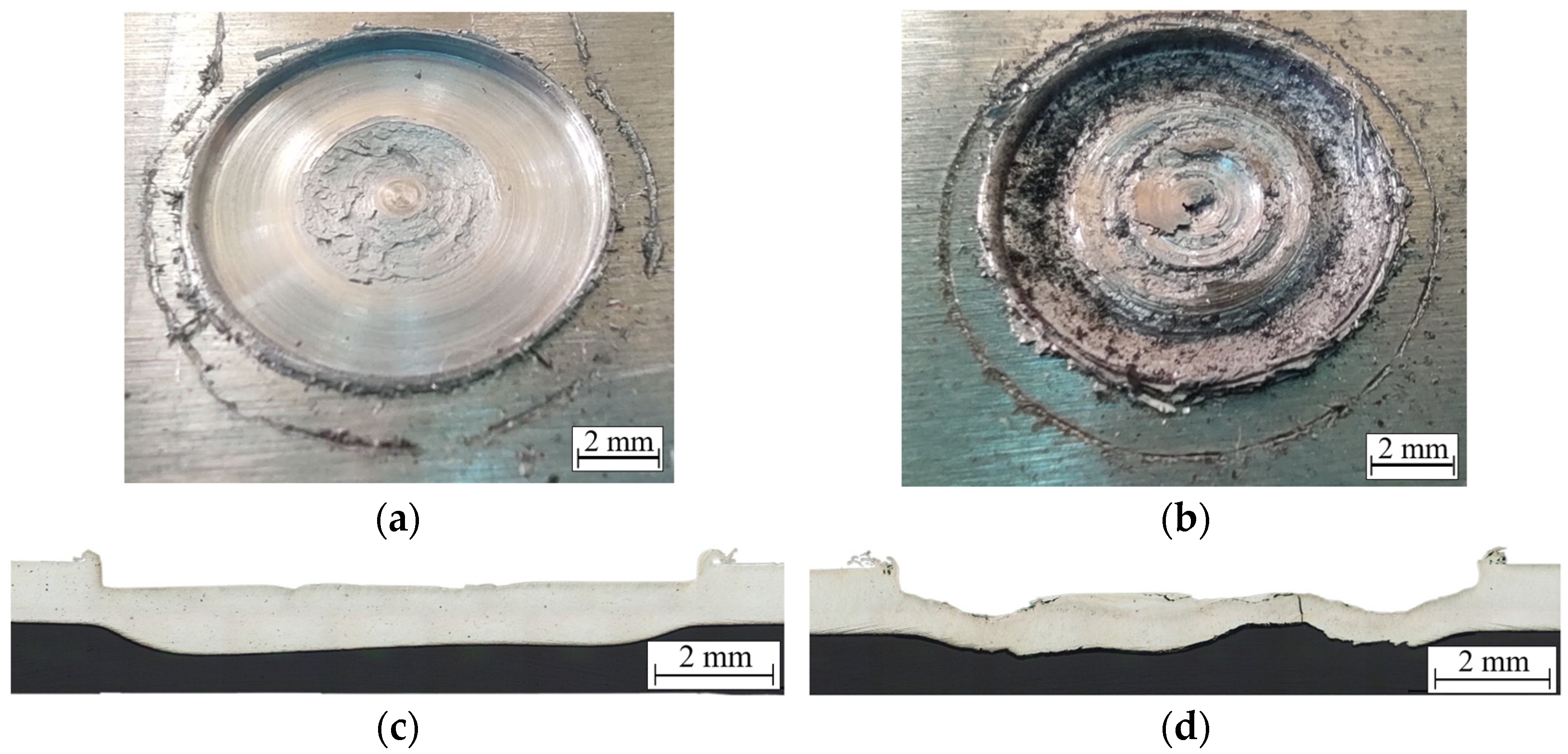
3.1. Plunge Depth
3.2. Dwell Time
3.3. Triple Spot Welding
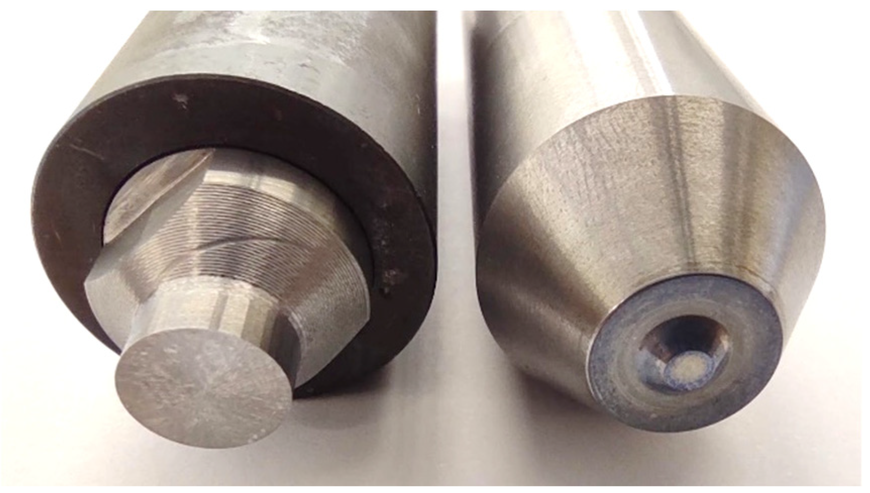
3.4. Pinless Tool versus Conical Pin Tool
4. Conclusions
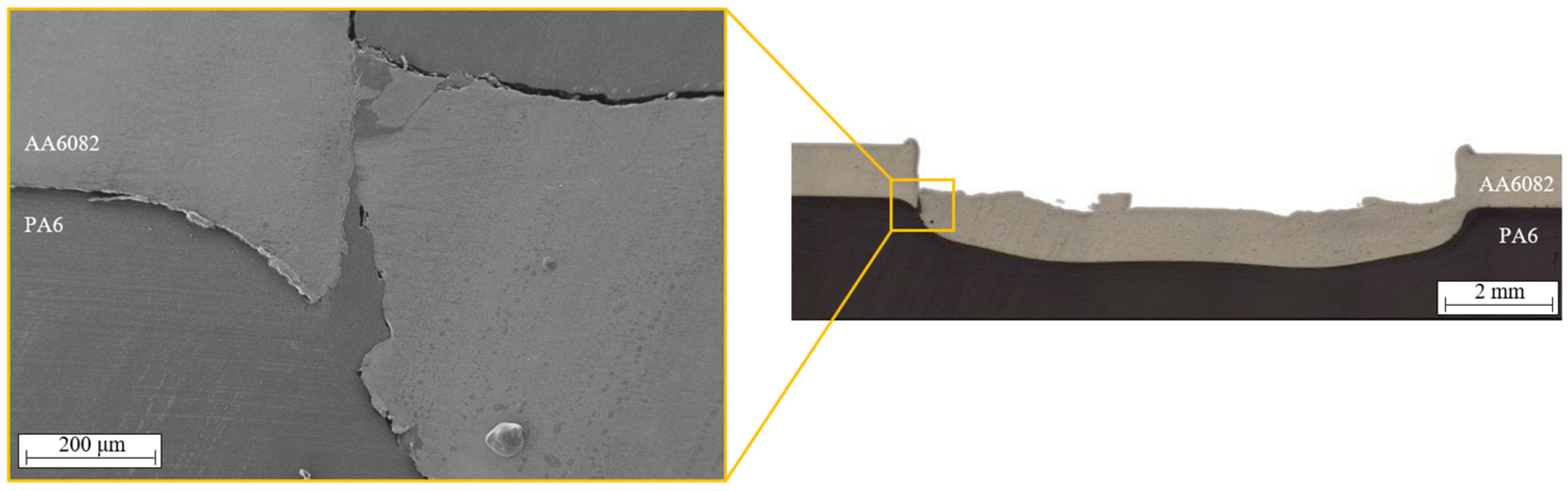
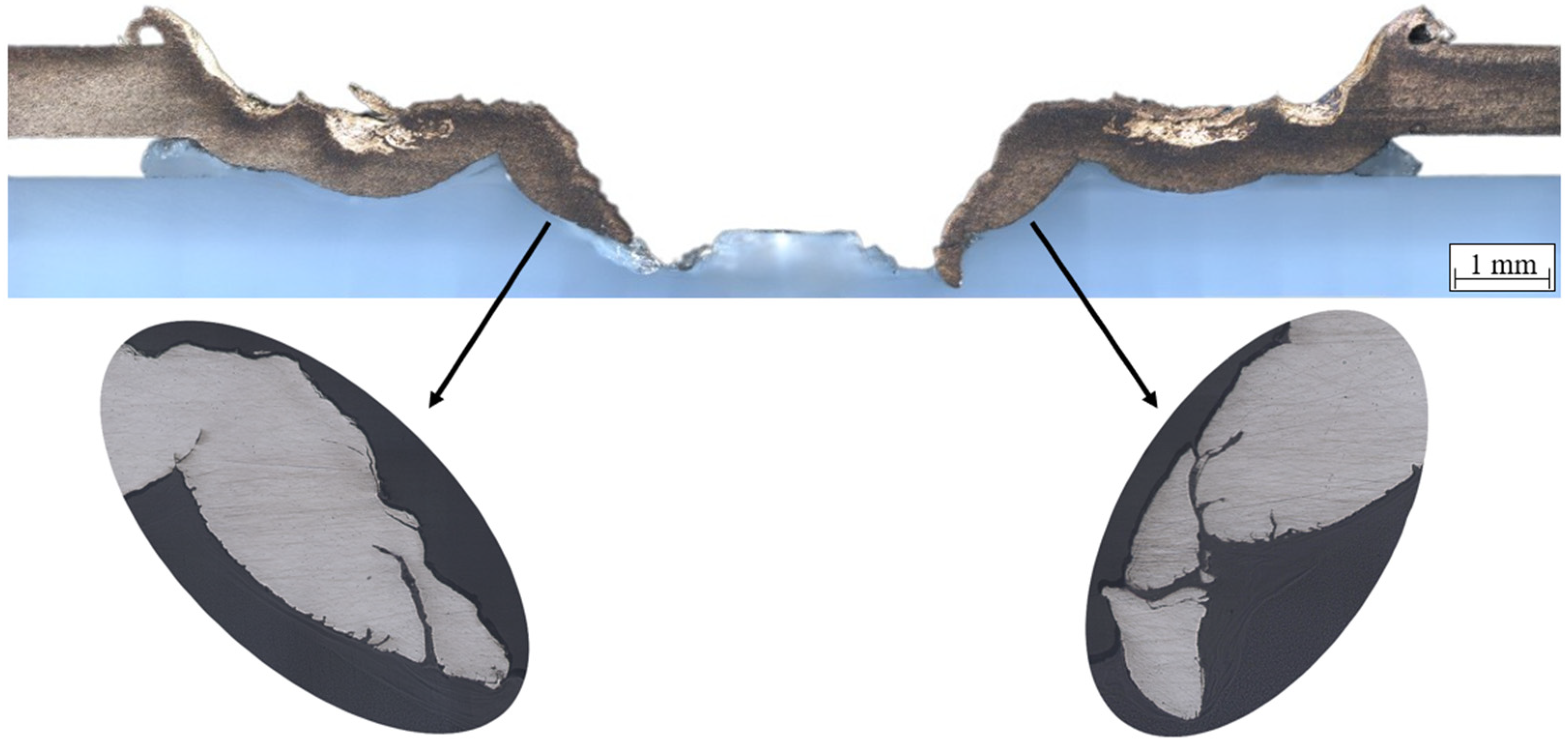
- The increase of plunge depth leads to an increase in mechanical strength up to the point where excessive penetration (0.5 mm) gives rise to rupture of the aluminium plate;
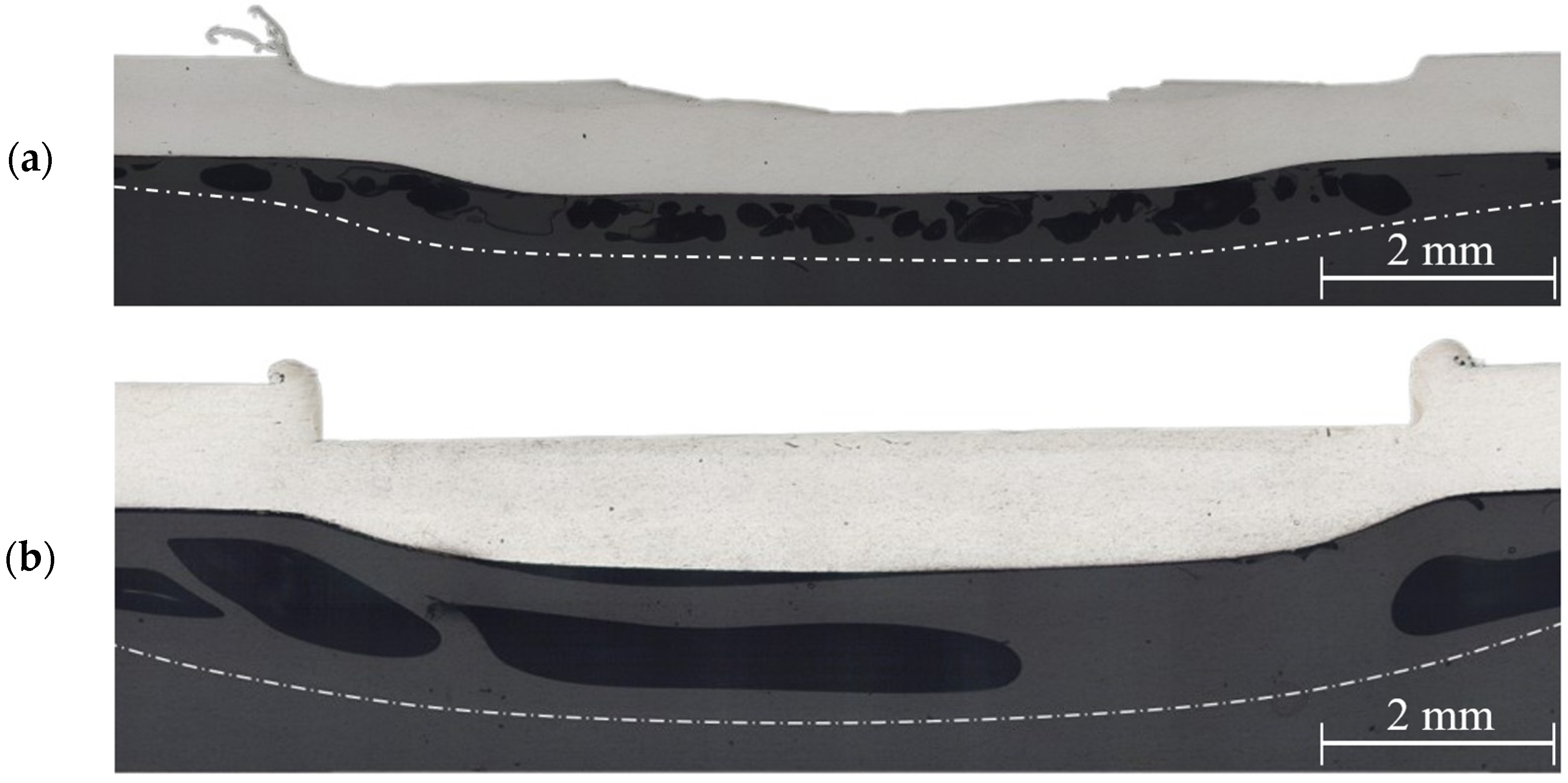
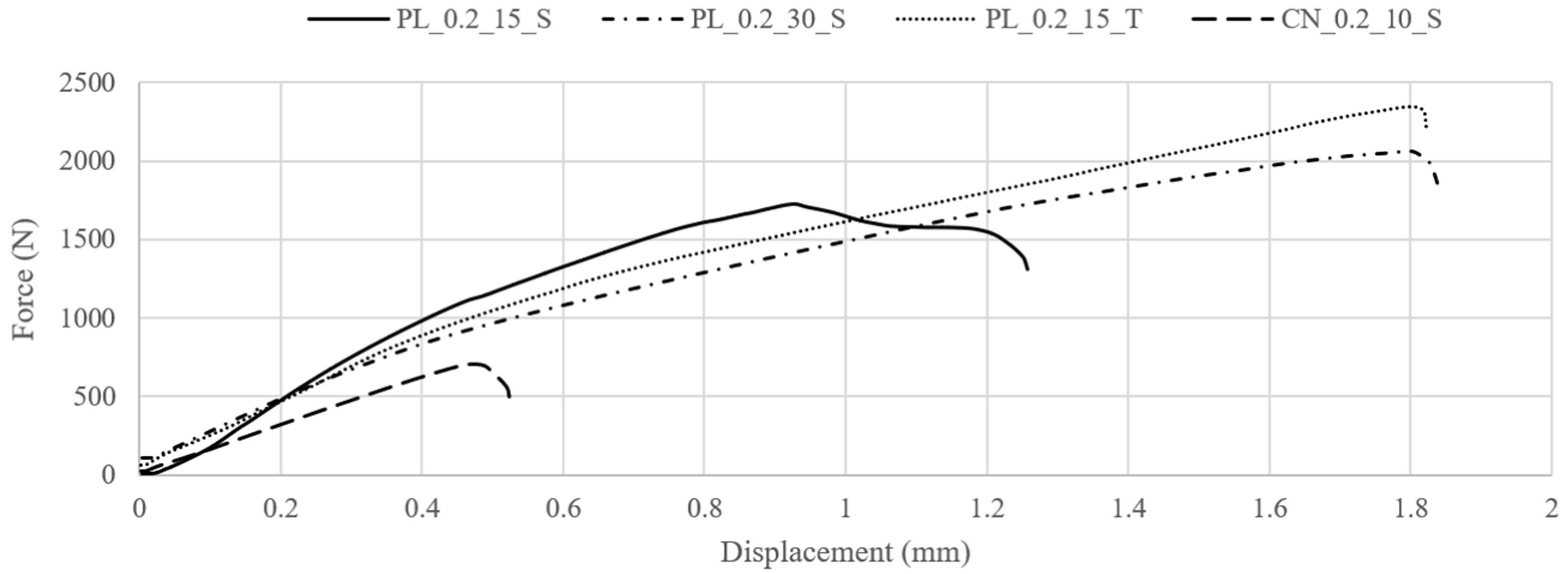
- Although the pore defects tend to increase with longer dwell times, an improvement in maximum load under tensile-shear testing resulted from the increase of the joining area. As a result, the increase of dwell time from 15 to 30 s resulted in the increase of joint strength from 1700 to 2100 N (an increment of about 24%);
- Triple spot welding was successfully demonstrated as the multiple welds do not result in the separation of previous welds, improving the mechanical performance when compared to single spot welds. The weld with the best mechanical behaviour was produced with multiple spot welding, which failed for a maximum load of about 2350 N (an increment of about 38%);
- The use of a more conventional tool with a conical pin and a concave shoulder result in the production of FSS welds between thin aluminium plates and PA6 with a lower strength (700 N) than those produced with a pinless tool. However, despite the lower strength of the weld produced with the tool with a conical pin, the interface of the materials was more irregular, indicating a better macro-interlocking between both materials. Therefore, despite not being suitable for the welding conditions of this study, the tool’s potential for joints with thicker aluminium plates was demonstrated.
Author Contributions
Funding
Data Availability Statement
Conflicts of Interest
References
- Lambiase, F.; Genna, S.; Kant, R. A procedure for calibration and validation of FE modelling of laser-assisted metal to polymer direct joining. Opt. Laser Technol. 2018, 98, 363–372. [Google Scholar] [CrossRef]
- Amancio-Filho, S.T.; Bueno, C.; dos Santos, J.F.; Huber, N.; Hage, E. On the feasibility of friction spot joining in magnesium/fiber-reinforced polymer composite hybrid structures. Mater. Sci. Eng. A 2011, 528, 3841–3848. [Google Scholar] [CrossRef]
- Cho, J.H.; Jae Kim, W.; Gil Lee, C. Texture and microstructure evolution and mechanical properties during friction stir welding of extruded aluminum billets. Mater. Sci. Eng. A 2014, 597, 314–323. [Google Scholar] [CrossRef]
- Meng, X.; Huang, Y.; Xie, Y.; Li, J.; Guan, M.; Wan, L.; Dong, Z.; Cao, J. Friction self-riveting welding between polymer matrix composites and metals. Compos. Part A Appl. Sci. Manuf. 2019, 127, 105624. [Google Scholar] [CrossRef]
- Pereira, M.A.R.; Galvão, I.; Costa, J.D.; Leal, R.M.; Amaro, A.M. Joining of Polyethylene Using a Non-Conventional Friction Stir Welding Tool. Materials 2022, 15, 7639. [Google Scholar] [CrossRef] [PubMed]
- Thomas, W.M.; Nicholas, E.D.; Needham, J.C.; Murch, M.G.; Templesmith, P.; Dawes, C.J. Friction Stir Butt Welding. U.S. Patent No. 5460317, 24 October 1995. [Google Scholar]
- Thomas, W.; Nicholas, E. Friction stir welding for the transportation industries. Mater. Des. 1997, 18, 269–273. [Google Scholar] [CrossRef]
- Pereira, M.A.R.; Amaro, A.M.; Reis, P.N.B.; Loureiro, A. Effect of Friction Stir Welding Techniques and Parameters on Polymers Joint Efficiency—A Critical Review. Polymers 2021, 13, 2056. [Google Scholar] [CrossRef]
- Pereira, M.A.R.; Galvão, I.; Costa, J.D.; Amaro, A.M.; Leal, R.M. Joining of Fibre-Reinforced Thermoplastic Polymer Composites by Friction Stir Welding—A Review. Appl. Sci. 2022, 12, 2744. [Google Scholar] [CrossRef]
- Lambiase, F.; Balle, F.; Blaga, L.A.; Liu, F.; Amancio-Filho, S.T. Friction-based processes for hybrid multi-material joining. Compos. Struct. 2021, 266, 113828. [Google Scholar] [CrossRef]
- Sun, Y.; Gong, W.; Feng, J.; Lu, G.; Zhu, R.; Li, Y. A Review of the Friction Stir Welding of Dissimilar Materials between Aluminum Alloys and Copper. Metals 2022, 12, 675. [Google Scholar] [CrossRef]
- Yusof, F.; Miyashita, Y.; Seo, N.; Mutoh, Y.; Moshwan, R. Utilising friction spot joining for dissimilar joint between aluminium alloy (A5052) and polyethylene terephthalate. Sci. Technol. Weld. Join. 2012, 17, 544–549. [Google Scholar] [CrossRef]
- Yusof, F.; bin Muhamad, M.R.; Moshwan, R.; bin Jamaludin, M.F.; Miyashita, Y. Effect of surface states on joining mechanisms and mechanical properties of aluminum alloy (A5052) and Polyethylene Terephthalate (PET) by dissimilar friction spot welding. Metals 2016, 6, 101. [Google Scholar] [CrossRef]
- Lambiase, F.; Paoletti, A.; Grossi, V.; Ilio, A. Di Friction assisted joining of aluminum and PVC sheets. J. Manuf. Process. 2017, 29, 221–231. [Google Scholar] [CrossRef]
- Lambiase, F.; Paoletti, A.; Grossi, V.; Genna, S. Improving energy efficiency in friction assisted joining of metals and polymers. J. Mater. Process. Technol. 2017, 250, 379–389. [Google Scholar] [CrossRef]
- Lambiase, F.; Grossi, V.; Paoletti, A. Defects formation during Friction Assisted Joining of metals and semi crystalline polymers. J. Manuf. Process. 2021, 62, 833–844. [Google Scholar] [CrossRef]
- André, N.M.; dos Santos, J.F.; Amancio-Filho, S.T. Evaluation of Joint Formation and Mechanical Performance of the AA7075-T6/CFRP Spot Joints Produced by Frictional Heat. Materials 2019, 12, 891. [Google Scholar] [CrossRef] [PubMed]
- Goushegir, S.M. Friction spot joining (FSpJ) of aluminum-CFRP hybrid structures. Weld. World 2016, 60, 1073–1093. [Google Scholar] [CrossRef]
- Goushegir, S.M.; dos Santos, J.F.; Amancio-Filho, S.T. Friction Spot Joining of aluminum AA2024/carbon-fiber reinforced poly(phenylene sulfide) composite single lap joints: Microstructure and mechanical performance. Mater. Des. 2014, 54, 196–206. [Google Scholar] [CrossRef]
- Esteves, J.V.; Goushegir, S.M.; dos Santos, J.F.; Canto, L.B.; Hage, E.; Amancio-Filho, S.T. Friction spot joining of aluminum AA6181-T4 and carbon fiber-reinforced poly(phenylene sulfide): Effects of process parameters on the microstructure and mechanical strength. Mater. Des. 2015, 66, 437–445. [Google Scholar] [CrossRef]
- Lambiase, F.; Paoletti, A. Mechanical behavior of AA5053/polyetheretherketone (PEEK) made by Friction Assisted Joining. Compos. Struct. 2018, 189, 70–78. [Google Scholar] [CrossRef]
- Aliasghari, S.; Skeldon, P.; Zhou, X.; Ghorbani, M. Influence of PEO and mechanical keying on the strength of AA 5052 alloy/polypropylene friction stir spot welded joints. Int. J. Adhes. Adhes. 2019, 92, 65–72. [Google Scholar] [CrossRef]
- Aliasghari, S.; Ghorbani, M.; Skeldon, P.; Karami, H.; Movahedi, M. Effect of plasma electrolytic oxidation on joining of AA 5052 aluminium alloy to polypropylene using friction stir spot welding. Surf. Coat. Technol. 2017, 313, 274–281. [Google Scholar] [CrossRef]
- Aliasghari, S.; Skeldon, P.; Zhou, X.; Hashimoto, T. Effect of an anodizing pre-treatment on AA 5052 alloy/polypropylene joining by friction stir spot welding. Mater. Sci. Eng. B 2019, 245, 107–112. [Google Scholar] [CrossRef]
- Asadollahi, M.; Jabbari, N.; Nakhodchi, S.; Salimi, H.; Khodaparast, H.H. Analysis of tensile-shear strength of single and multi-friction stir spot welding joints under fixed welding process conditions. Proc. Inst. Mech. Eng. Part C J. Mech. Eng. Sci. 2020, 234, 4893–4904. [Google Scholar] [CrossRef]


| Material | Si | Fe | Cu | Mn | Mg | Cr | Zn | Ti | Al |
|---|---|---|---|---|---|---|---|---|---|
| AA6082-T6 | 0.7–1.3 | <0.5 | <0.1 | 0.4–1 | 0.6–1.2 | <0.25 | <0.2 | <0.1 | Balance |
| Property | AA6082-T6 | PA6 |
|---|---|---|
| Density (g/cm3) | 2.70 | 1.14 |
| Ultimate tensile strength (MPa) | 290–310 | 55 * |
| Yield Strength (MPa) | 250–260 | 38 * |
| Vickers Microhardness (HV) | 103 * | 5.8–6.8 * |
| Thermal conductivity (W/K·m) | 150–180 | 0.28 |
| Melting temperature (°C) | 550–650 | 220 |
| Elongation at break (%) | 10 | 170 * |
| Designation * | Tool Geometry | Plunge Depth (mm) | Dwell Time (s) | Welding Spot Strategy |
|---|---|---|---|---|
| PL_0.1_15_S | Pinless | 0.1 | 15 | Single |
| PL_0.2_15_S | Pinless | 0.2 | 15 | Single |
| PL_0.3_15_S | Pinless | 0.3 | 15 | Single |
| PL_0.4_15_S | Pinless | 0.4 | 15 | Single |
| PL_0.5_15_S | Pinless | 0.5 | 15 | Single |
| PL_0.2_30_S | Pinless | 0.2 | 30 | Single |
| PL_0.2_15_T | Pinless | 0.2 | 15 | Triple |
| CN_0.2_10_S | Conical | 0.2 | 10 | Single |
Disclaimer/Publisher’s Note: The statements, opinions and data contained in all publications are solely those of the individual author(s) and contributor(s) and not of MDPI and/or the editor(s). MDPI and/or the editor(s) disclaim responsibility for any injury to people or property resulting from any ideas, methods, instructions or products referred to in the content. |
© 2024 by the authors. Licensee MDPI, Basel, Switzerland. This article is an open access article distributed under the terms and conditions of the Creative Commons Attribution (CC BY) license (https://creativecommons.org/licenses/by/4.0/).
Share and Cite
Pereira, M.A.R.; Galvão, I.; Costa, J.D.; Leal, R.M.; Amaro, A.M. Friction Stir Spot Welding of Thin Aluminium Sheets to Polyamide 6: A Study of the Welding Parameters and Strategies. J. Compos. Sci. 2024, 8, 21. https://doi.org/10.3390/jcs8010021
Pereira MAR, Galvão I, Costa JD, Leal RM, Amaro AM. Friction Stir Spot Welding of Thin Aluminium Sheets to Polyamide 6: A Study of the Welding Parameters and Strategies. Journal of Composites Science. 2024; 8(1):21. https://doi.org/10.3390/jcs8010021
Chicago/Turabian StylePereira, Miguel A. R., Ivan Galvão, José Domingos Costa, Rui M. Leal, and Ana M. Amaro. 2024. "Friction Stir Spot Welding of Thin Aluminium Sheets to Polyamide 6: A Study of the Welding Parameters and Strategies" Journal of Composites Science 8, no. 1: 21. https://doi.org/10.3390/jcs8010021
APA StylePereira, M. A. R., Galvão, I., Costa, J. D., Leal, R. M., & Amaro, A. M. (2024). Friction Stir Spot Welding of Thin Aluminium Sheets to Polyamide 6: A Study of the Welding Parameters and Strategies. Journal of Composites Science, 8(1), 21. https://doi.org/10.3390/jcs8010021