Article

Analysis of Ballistic Impact of 7.62 mm FMJ M80 Rifle Projectile into Twaron/UHMWPE Composite Armor

1
Department of Mechanical Engineering, Faculty of Military Technology, University of Defence, Kounicova 65, 602 00 Brno, Czech Republic
2
Institute of Manufacturing Technology, Faculty of Mechanical Engineering, Brno University of Technology, Technicka 2896/2, 616 69 Brno, Czech Republic
*
Author to whom correspondence should be addressed.
J. Compos. Sci. 2023, 7(9), 390; https://doi.org/10.3390/jcs7090390
Submission received: 20 July 2023 / Revised: 8 September 2023 / Accepted: 12 September 2023 / Published: 14 September 2023

Abstract

:
This article deals with the ballistic impact of the 7.62 mm FMJ M80 rifle projectile into the laminated Twaron/UHMWPE composite armor. The armor composition consisted of composite panels made from Twaron CT 747 para-aramid fabric and ultra-high-molecular-weight Endumax Shield XF33 polyethylene. To analyze the ballistic impact and to verify the resistance of the designed armor according to the NATO AEP 4569 STANAG standard, protection level 1, 7.62 × 51 mm FMJ NATO M80 rifle cartridges with lead projectiles were used in the ballistic experiment. After the projectile impact, the damage failure mechanisms of the composite panels were documented. As part of the evaluation of the experiments, the initial microstructure of the composite panels was documented, and subsequently, the damaged areas of the composite armor after the ballistic experiment were also documented. Optical and scanning electron microscopy were used to document the structures. The important parameter of composite armor is its mechanical properties. The surface hardness of the composite panels was measured by the Shore D method using the hardness tester DIGI-Test II. The results obtained from the ballistic experiment demonstrate that the designed Twaron/Endumax armor was not penetrated. This armor has sustained multiple impacts for all three 7.62 mm FMJ M80 projectiles and is suitable for the construction of armor protection.

1. Introduction

The most important factors influencing the design of armored equipment, especially tanks and combat vehicles, introduced in the military equipment include firepower, armor protection and mobility. Because these properties are significantly interrelated and interact in terms of design, it is advisable to choose the suitable compromise [1,2,3,4,5].
The main purpose of armor is to provide sufficient protection against the destructive effects of projectiles fired from firearms and anti-tank and anti-aircraft weapons. The development of armor protection is also connected to and influenced by tactics and strategies used in combat conflicts, e.g., the use of improvised explosive devices and unconventional weapons in asymmetric conflict [1,2,3,5].
In the context of the constantly evolving combat environment, materials engineering is developing sophisticated layered armor. The composition of this armor is composed of several layers of different materials. The front strike face is a metal or ceramic layer with high hardness that is used to deform the projectile or deflect it and reduce its effectiveness. Other layers are made of composite materials to dissipate and absorb the kinetic energy of the projectiles or their fragments [1,2,5,6,7,8,9,10,11,12].
The issue of ballistic resistance of composite ballistic protection systems has received considerable attention. The ballistic performance of layered composite ballistic protections has been described by Braga et al. [13], Demosthenes et al. [14], Scazzosi et al. [15], Mujiyono et al. [16], etc. In their study, Braga et al. [13] compared the ballistic resistance of polyester composites that were reinforced with curaua fibers. The tested composites were subjected to ballistic impact of 7.62 mm caliber projectiles. These composites were reinforced with 0, 10, 20 and 30 vol% curaua fibers. The ballistic results showed that the pure polyester resin exhibited the highest ability to absorb the kinetic energy of the projectiles, but its fragmentation characteristic is unsuitable for military applications that depend on achieving the ability to resist multiple hits. After ballistic testing, the composite reinforced with 30 vol% curaua fibers showed higher cohesion. Demosthenes et al. [14] evaluate the ballistic resistance of the layered armor system subjected to the high-velocity impact of 7.62 × 51 mm projectiles. This armor consisted of a 10 mm hexagonal alumina ceramic plate; the second layer consisted of a 10 mm epoxy composite with 10 vol%, 20 vol% and 30 vol% buriti fabric. The last part was formed by the 5 mm aluminum alloy sheet 5052-H34. From the ballistic results, all composites showed the satisfactory back side signature (BFS), which was significantly lower than the 44 mm lethal trauma specified by the NIJ 0101.06 standard. However, it is worth noting that only the composite reinforced with 30 vol% buriti fabric retains full integrity and guarantees protection against the other 7.62 mm projectile. Scazzosi et al. [15] discuss the experimental and numerical evaluation of the ballistic resistance of the layered ballistic protection, which consisted of Al2O3 ceramic and para-aramid fabric Kevlar 29 impregnated with epoxy resin. The ballistic protection was tested with projectiles of 7.62 × 51 mm with an impact velocity of (800–1000) m/s. From the results obtained, the limiting ballistic velocity was determined to be 816.53 m/s. Mujiyono et al. [16] analyzed the ballistic performance of the layered ballistic protection, which was composed of the front strike layer and the rear tougher layer. The front strike layer was composed of ballistic ceramic (tungsten carbide) and the rear tougher layer was composed of ramie fibers with epoxy resin. Ballistic resistance was tested with 7.62 × 51 mm projectiles with lead cores and 7.62 × 51 mm AP with steel cores. These projectiles were unable to penetrate the given layered armor, but brittle fractures occurred with the ballistic ceramic.
These composite materials consist of two or more phases with different properties. They are separated from other materials by their anisotropy. They are composed of a matrix and supporting reinforcement. The matrix is the base material and ensures the compactness of the composite. It is characterized by high elongation, low specific gravity and good wettability. The matrix protects the reinforcement from mechanical and chemical damage, as well as from external influences. The load transfer is decisively influenced by the supporting reinforcement, which consists of particles or fibers and is characterized by high strength and stiffness. The combination of matrix and supporting reinforcement results in a synergistic effect that provides better properties than each of the individual phases [6,17,18].
The main goal of this article was to obtain the necessary information about the standardized polymer fibers, which were further used to construct the composite armor, based on the performed experiment. The ballistic resistance of the designed armor was tested according to the NATO AEP 4569 STANAG standard, protection level 1. In addition to testing the ballistic resistance of the designed armor, surface hardness measurements and microstructure evaluation of the composite materials were also performed. The results of the ballistic resistance testing of this armor provided important information on its effectiveness and ability to provide protection against rifle projectiles.
The designed layered composite armor, which combines the para-aramid fabric Twaron CT 747 and Endumax Shield XF33 represents the suitable material combination in this assembly, which, depending on the synergistic properties of these materials, guarantees the required ballistic protection according to the AEP standard, level 1. The properties of para-aramid fabric Twaron CT 747 and Endumax Shield XF33 provide high ballistic protection while preserving important factors such as low weight and high mobility for armoring military equipment. In general, the uniqueness of this type of composite armor is the ability to effectively resist and dissipate energy in multiple hits of the 7.62 mm FMJ NATO M80 projectile.

2. Materials and Methods

The most commonly used composite materials for the production of high-protection composite armor include aramid and UHMWPE (ultra-high-molecular-weight polyethylene) fibers [6,17,18,19].
Aramid fibers are synthetically oriented fibers. They are characterized by their low density of 1.44 g/cm3 and high tensile strength of up to 3300 MPa. The most common types of aramid fibers used in armor protection are Kevlar® and Twaron®. They are synthesized from the same monomer and are very similar in properties. They have high strength, stiffness and elongation. They are also resistant to abrasion, chemicals and heat. However, as with any material, aramid fibers have their limitations. They degrade when exposed to UV light and moisture. They are used for ballistic purposes in the form of fabrics and are supplied by the manufacturer in various fineness [6,17,20,21].
UHMWPE (ultra-high-molecular-weight polyethylene) fibers are made up of very long chains of polyethylene oriented in the same direction, which is the basis for their extreme tensile strength. These materials are characterized by high molecular weights ranging from 3–106 g/mol to 6–106 g/mol, high strength and abrasion resistance. They are characterized by a low coefficient of friction and this property allows their use also in arthroplasty for joint replacement. It is a chemically resistant material. It resists most chemicals, including acids, alkalis and other aggressive chemicals. Other advantages include low moisture absorption, UV resistance and good electrical insulation [6,18,19].
On the basis of their low density and high strength and their ability to absorb impact energy and transfer the load to the entire volume, they represent a perspective material choice for the construction of armor protection [3,22]. Armor protection and its durability depend on the mechanical and ballistic properties of the materials used (matrix and supporting reinforcement). For this reason, it is important to know the material and ballistic properties of the individual components or the system, as well as the capabilities and limitations of the composite panel manufacturing technologies.

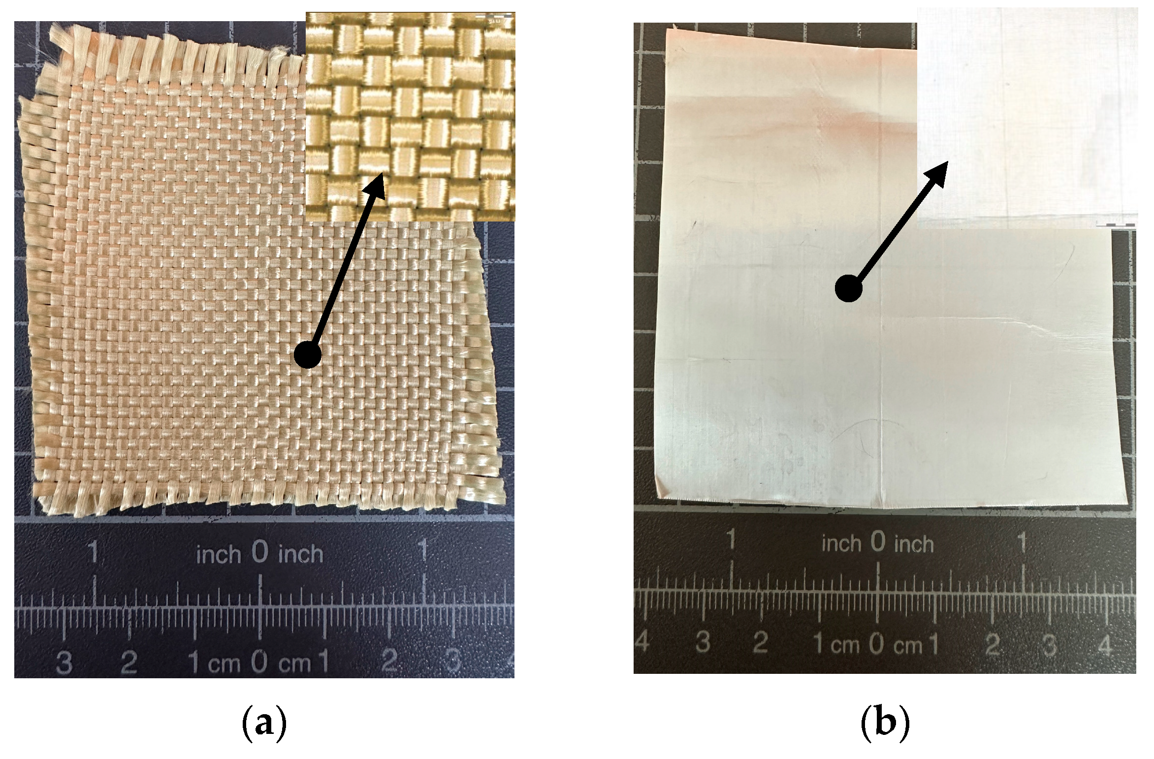
2.1. Material Properties of Composite Armor

For this experiment, the para-aramid fabric Twaron CT 747 (Teijin Aramid, Arnhem, The Netherlands) and the high molecular weight polyethylene Endumax Shield XF33 (Teijin Aramid, Arnhem, The Netherlands) were used (see Figure 1).
The properties of these composite materials are summarized in Table 1.

2.2. Manufacture of Composite Armor Twaron/UHMWPE

The individual composite panels were manufactured by using the VARTM method, autoclave technology and hot-pressing method (see Section 2.2.1, Section 2.2.2 and Section 2.2.3).
VARTM technology is based on the generation of a pressure differential. It is an injection technology that uses vacuum pressure. The reinforcement is placed under a vacuum sheet from which air is extracted and the generated vacuum enables the matrix to be saturated and impregnated with the supporting reinforcement [25,26,27,28].
Autoclave technology is a potential low-pressure technology for the manufacture of composite parts. The main technical equipment is the autoclave. It is a heated pressure chamber with a controlled atmosphere. Based on the selected program, the curing cycle is performed. The pressure ranges from 3–10 bar, and the curing temperature is 120–200 °C [27,29].
For the high-volume manufacturing of composite parts, the hot-pressing method has been widely used. To achieve the required shape, the composite material is inserted into a form consisting of two or more parts. This form is heated by an electric or heating medium. Pre-impregnated fabrics (prepregs) are used for this production. The prepared form with the composite material is then placed in a hydraulic press, which cures the resin on the base of a controlled thermal cycle. The temperature and pressure in the hydraulic press are precisely regulated and adjusted according to the required parameters for the specific part [27,30,31].

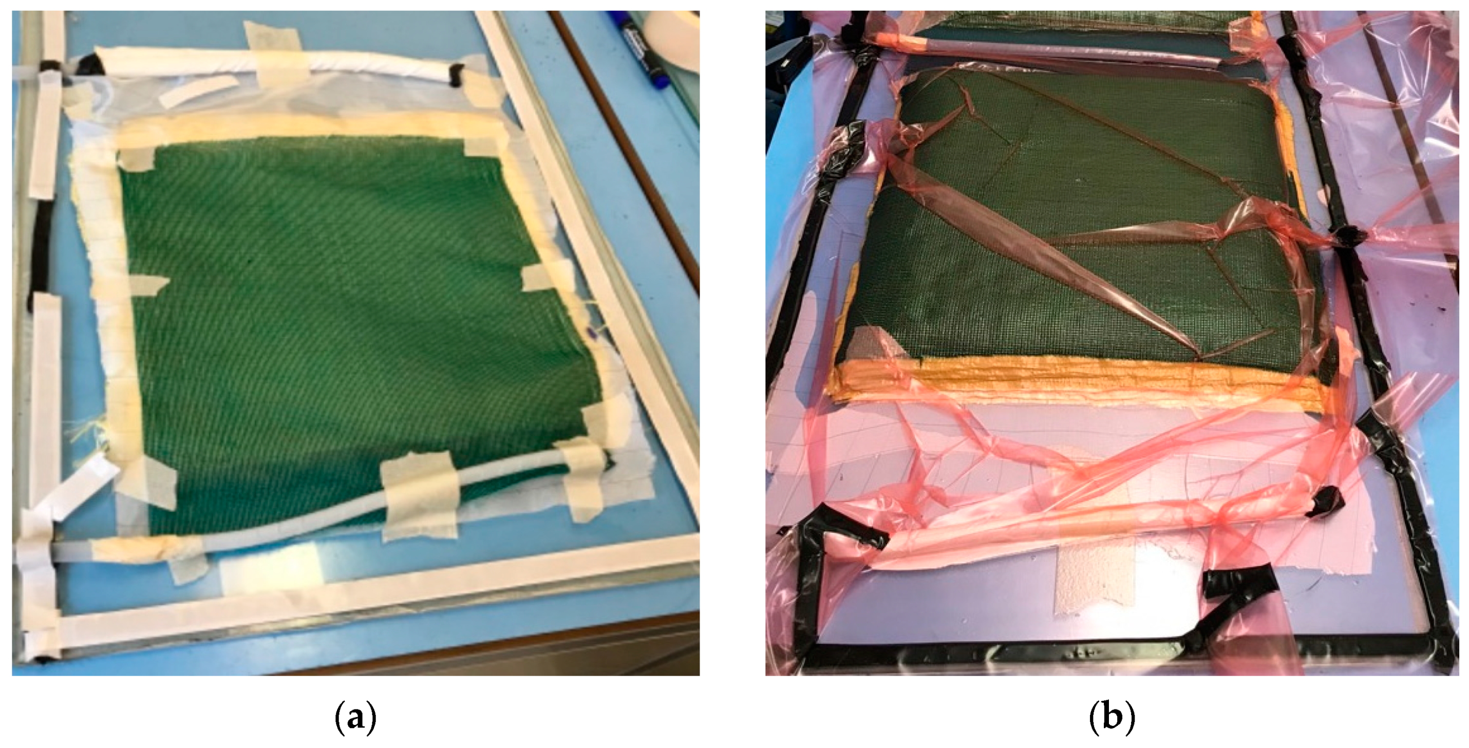
2.2.1. VARTM Technology

The cut para-aramid fabric Twaron CT 747 with the required number of layers was layered on the surface of the glass form. A hermetically closed space was created by using vacuum sheeting and butyl adhesive tape. This space was evacuated by the effect of the evacuator to create a vacuum. The vacuum effect resulted in the aspiration of the matrix (LG700 + HG700, stoichiometric ratio 100:30) and subsequent impregnation through the predefined para-aramid fabric. The impregnation was followed by the curing of the matrix at room temperature at 20 °C. The curing time was 20 h. The whole process of manufacturing the composite panel by VARTM technology is shown in Figure 2.

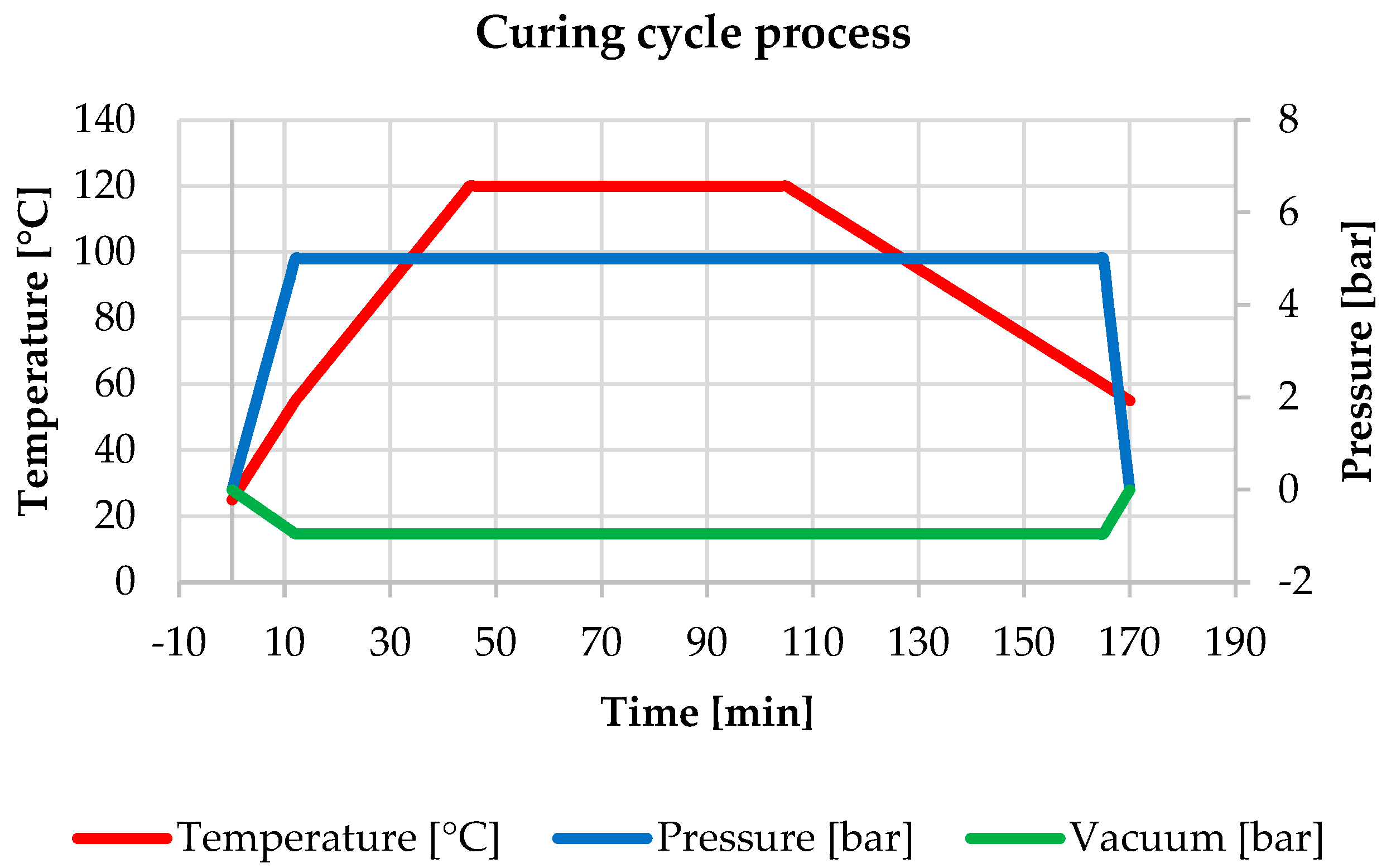
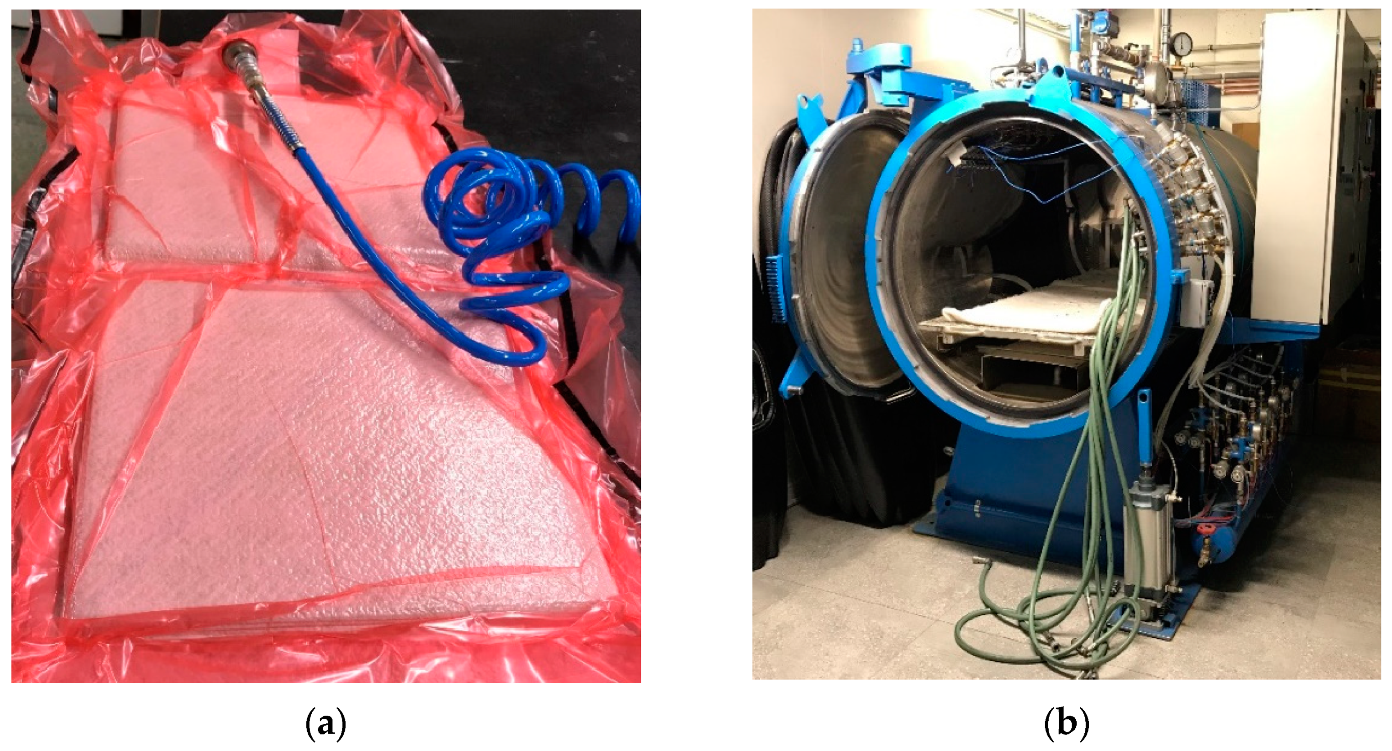
2.2.2. Autoclave Technology

After cutting and vacuuming, the para-aramid fabric Twaron CT 747, ER68 was placed in the form, which was placed in the autoclave (Maroso s.r.l., Pianezze, Italy), (see Figure 3). During the process, the form was vacuum sealed and exposed to temperatures to ensure saturation of the para-aramid fabric. The process consisted of several stages, including curing and cooling. The curing process for the composite panel of Twaron CT 747, ER68 is shown in Figure 4.

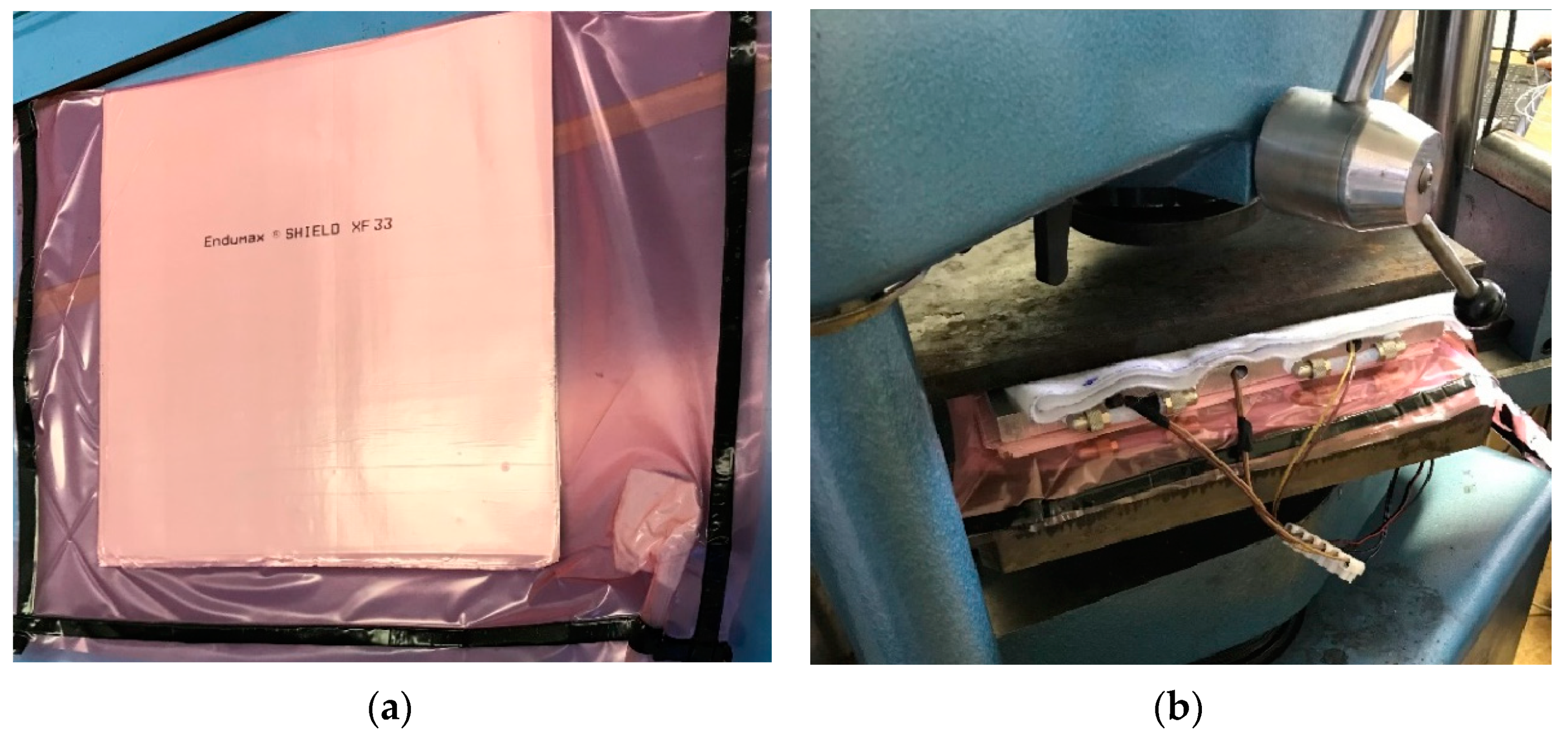
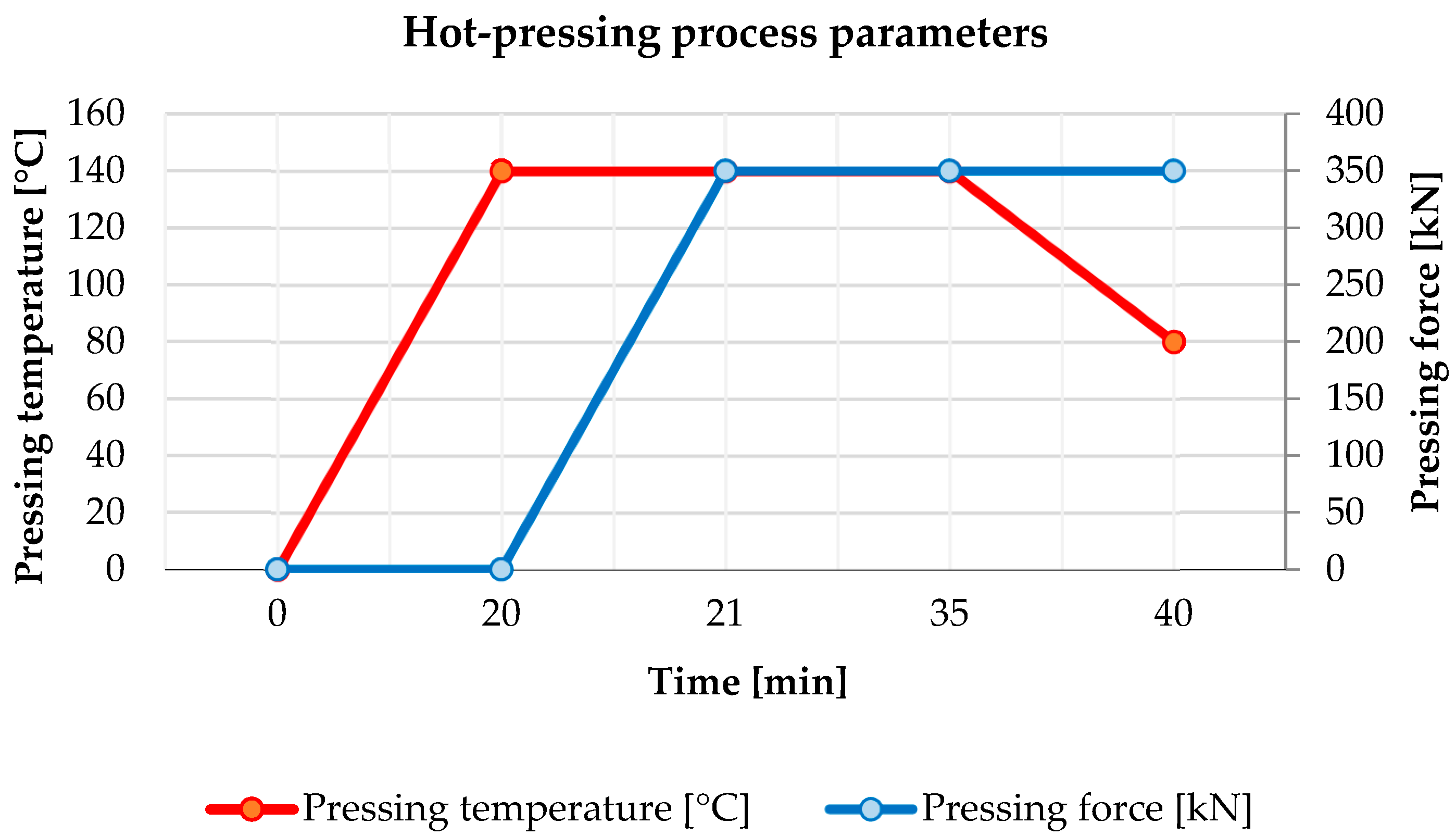
2.2.3. Hot−Pressing Technology

This technology was used for the manufacturing of the Endumax Shield XF33 composite panels. The ZD40 hydraulic press with a load capacity of up to 400 kN was used to press the composite materials. The Endumax Shield XF33 material was placed in an aluminum form, which was heated by heating patrons. The force application of the ZD40 machine was 350 kN. The temperature of the heated aluminum form was adjusted to 140 °C. The curing time for these panels was 20 min. After this time, controlled cooling to 80 °C followed. The preparation and manufacturing of the composite panels is shown in Figure 5. The hot-pressing process parameters are shown in Figure 6.
The mentioned technologies were used to manufacture four composite panels with the following parameters, which are shown in Table 2.

2.3. Testing of Manufactured Composite Panels

To achieve the higher ballistic resistance of armor, the configuration of the armor is essential. The ballistic resistance of a composite armor configuration depends on the mechanical properties (hardness, strength and toughness), the type of projectile (geometry, material and construction) and the shooting conditions (impact velocity, shooting direction, etc.). Evaluation of the ballistic resistance of the designed armor is based on shooting experiments [2,3].
In general terms, the basic material properties of armor include hardness, yield strength, ultimate strength, elongation and toughness. This knowledge is necessary to design the optimal configuration of composite armor. As hardness increases, toughness decreases. To maintain the optimal ratio of hardness to toughness, composite panels are stacked in a gradient pattern so that the front strike layer has the highest hardness and this hardness decreases with the rear layer [3,32,33].

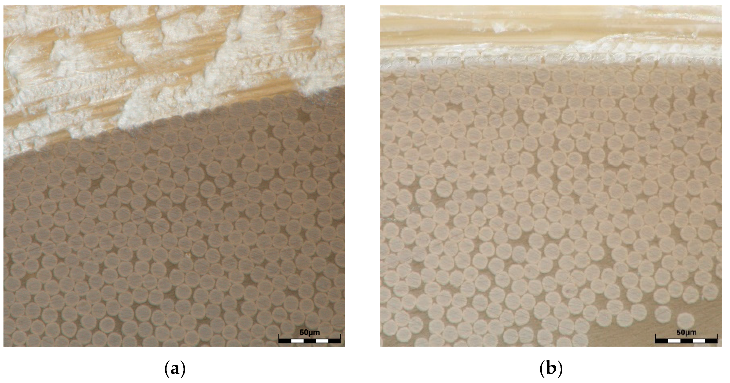
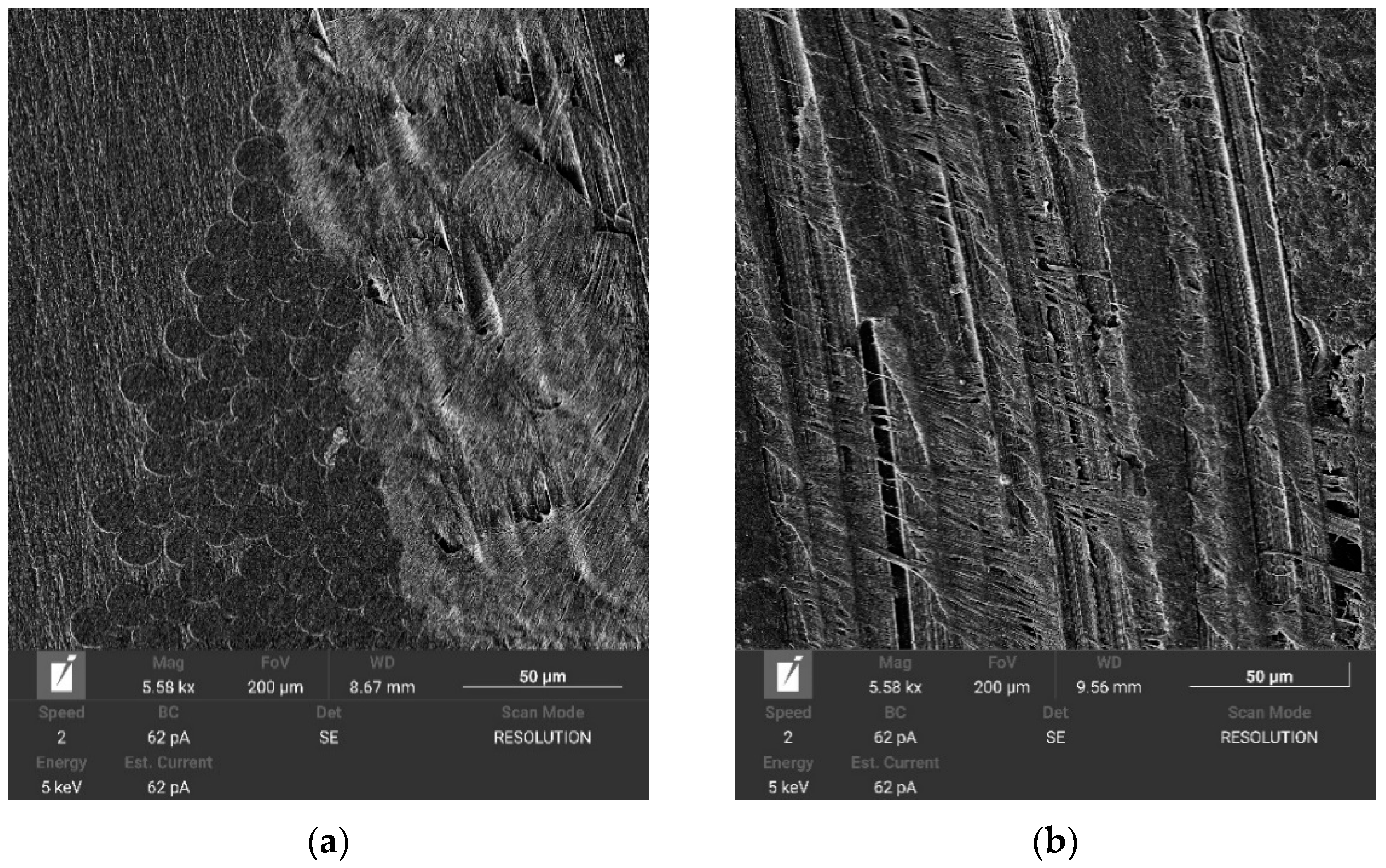
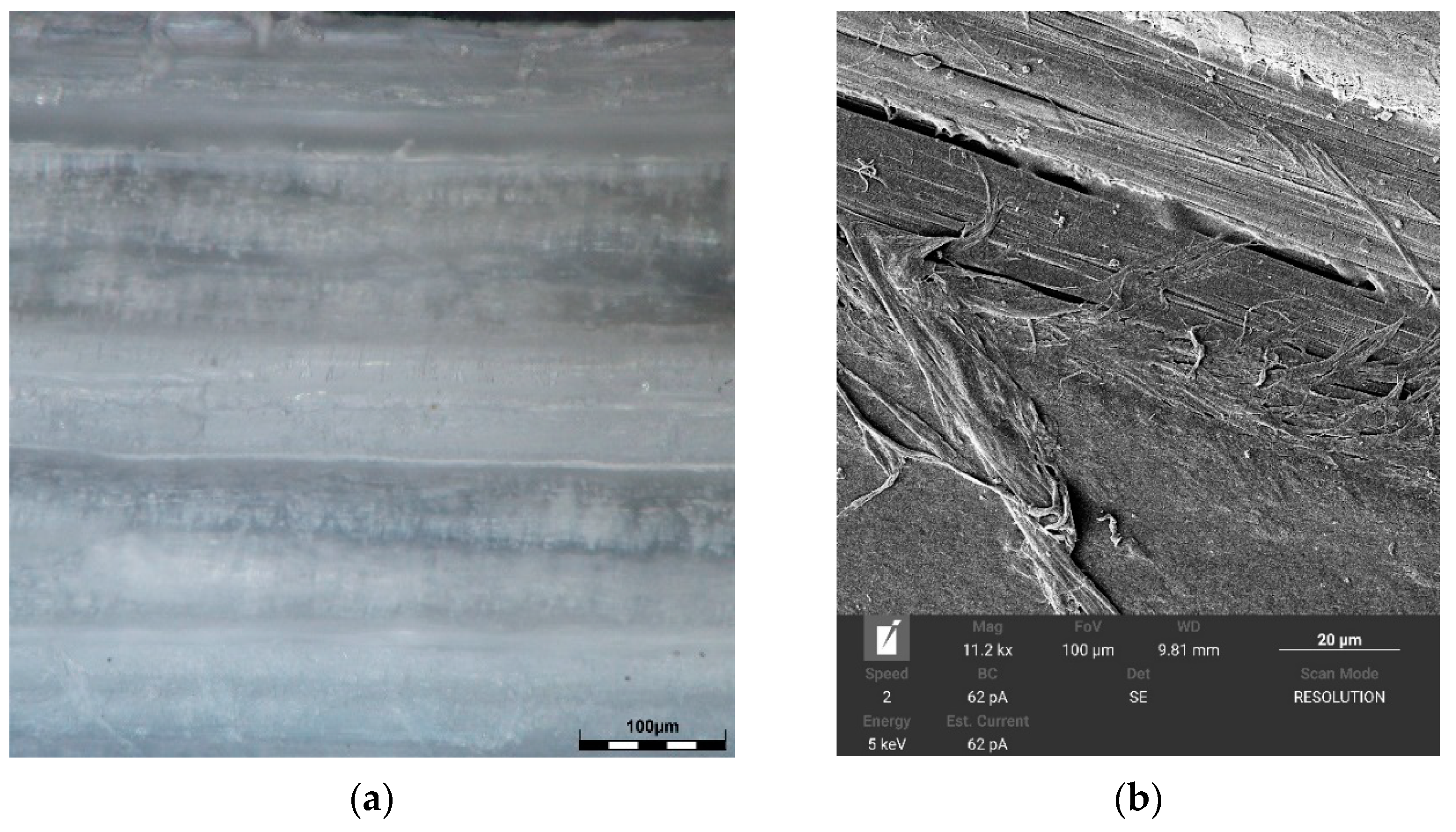
2.3.1. Surface Hardness and Microstructure of Composite Panels

To measure the surface hardness of composite materials, the Shore D method was used, which allows the measurement of the hardness of nonmetallic materials (polymers, hard synthetic plastics, thermoplastics, vinyl coatings, etc.). The Shore D surface hardness is measured by an indenter that is pressed into the material by an impact force using a calibrated spring, and the surface is deformed to a certain depth. After the indenter is released, the rate of return to its original position is measured [34,35].
The microstructure of the composite panels was observed by using the Olympus DSX500i inverted optodigital microscope (Olympus, Prague, Czech Republic) and the TESCAN MIRA 4 scanning electron microscope (Tescan, Brno, Czech Republic). The pictures of the cross-sections of the composite panels of Twaron CT 747, ER68 and Twaron CT 747, LG700 + HG700 are shown in Figure 7 and Figure 8. The pictures of the cross-sections of the Endumax Shield XF33 composite panel are shown in Figure 9.

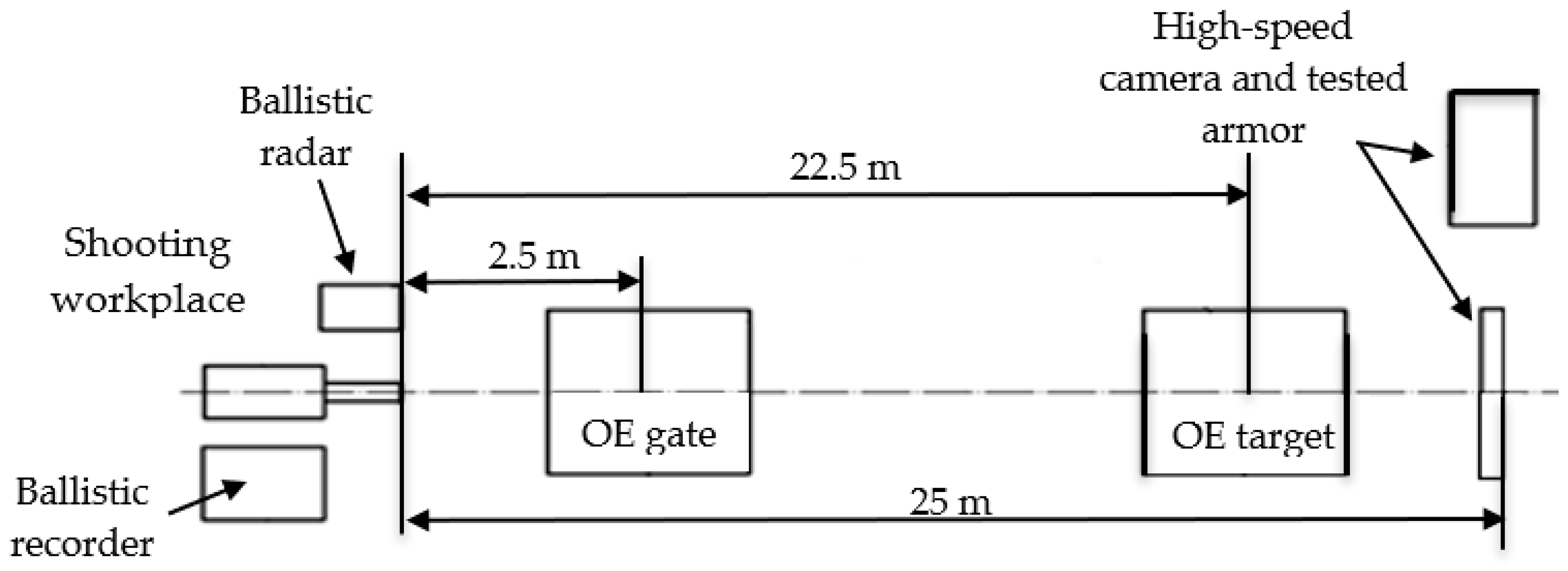
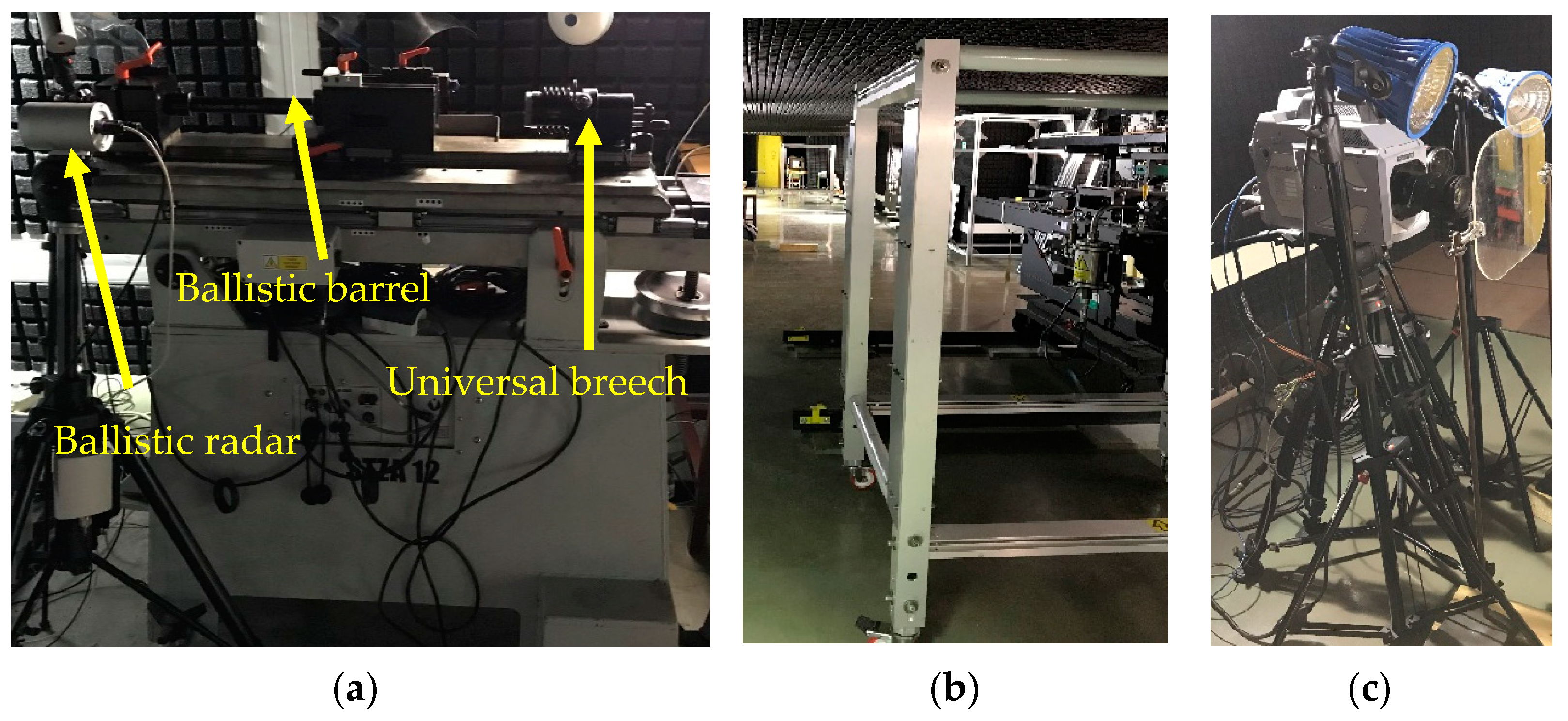
2.3.2. Ballistic Testing of Composite Panels

Ballistic testing is the essential process for developing, certifying and verifying the ballistic resistance of protective equipment. The level of ballistic protection is evaluated according to the national and international standards. In general, these standards deal with the assessment of the ballistic protection of the individuals and of the vehicles, whereas the protection of the individuals is recognized as wearable and nonwearable [6,22].
There are several internationally recognized organizations and institutions deter-mining ballistic standards, norms and regulations [6].
In the Czech Republic, the national standard for evaluating the level of ballistic protection of individuals is the ČSN 39 5360. Furthermore, in the Czech Republic, the following US and German national standards are recognized: NIJ 0101.06 (USA) and VPAM APR 2006 (GER). Next, especially for military purposes, the AEP 2920 was adopted in the Czech Republic as the ČOS 130027 in the case of protection against fragments [36,37,38,39,40].
Regarding the evaluation of ballistic protection of vehicles, the allied publication AEP-55 (STANAG 4569) is considered. This publication includes threats in the form of projectiles impacting with kinetic energy and shrapnel-simulating fragments (FSP) generated by the explosion of artillery ammunition. It also addresses protection against improvised explosive devices (IEDs) [39].
Because the presented and evaluated samples of ballistic protection are intended for the ballistic protection of vehicles, the level of ballistic protection was tested in accordance with the AEP-55. The only exception was the range of the fire—the AEP-55 defines the 30 m distance; the real range of fire was 25 m because of the limitations of the ballistic laboratory of the University of Defence.
To perform the shooting experiment according to the STANAG 4569 AEP-55 standard, the specialized test polygon was used. The shooting polygon is shown in Figure 10 and was modified to the requirements of STANAG 4569 AEP-55. The testing distance for ballistic resistance testing of the composite armor Twaron/UHMWPE was 25 m.
To evaluate and record the impact of ballistic threats, special measuring equipment was used, which consisted of a shooting bench (Prototypa-ZM, STZA 12, Brno, Czech Republic) with a ballistic barrel (Prototype-ZM, 7.62 × 51 mm NATO EPVAT, Czech Republic) and universal breech (Prototypa-ZM, UZ-2002, Czech Republic), ballistic radar (Prototypa-ZM, DRS-01, Czech Republic), optoelectronic gate (Kistler, 2521A, Winterthur, Switzerland), ballistic recorder (Kistler, 2519A, Switzerland) and high-speed camera (Photron, SA-Z, Tokyo, Japan) with reflectors. The measurement equipment used in this experiment is shown in Figure 11.

3. Results and Discussion

This section discusses the results obtained by the experimental methods described above. The measured surface hardness of the composite panels and the verification of the ballistic resistance of the Twaron/UHMWPE layered composite armor are presented.

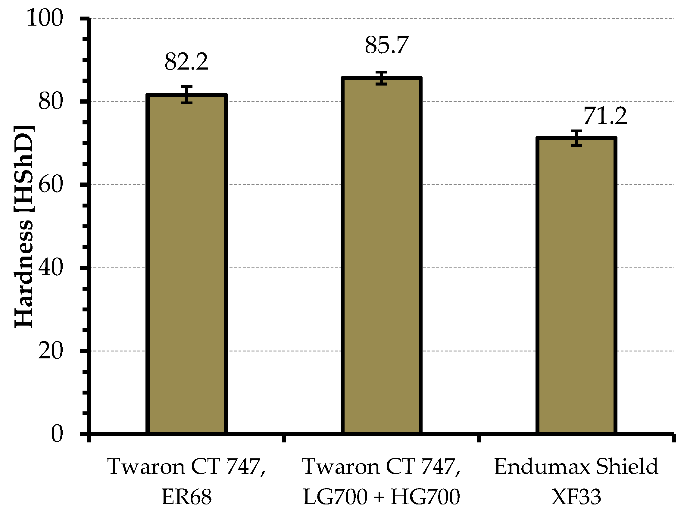
3.1. Surface Hardness of Composite Panels

The surface hardness of the composite panels was measured on the DIGI-Test II hardness tester by using the Shore D method. For each tested panel, 10 measurements were performed. The arithmetic average of the measurement results was determined (see Table 3). The graphical dependence expressing the comparison of the measured surface hardness data of the composite panels is shown in Figure 12.
Figure 12 shows that the highest surface hardness value is achieved by Twaron CT 747, LG700 + HG700, the second highest value is achieved by Twaron CT 747, ER68 and the lowest value is achieved by Endumax Shield XF33. According to this information, the optimal test configuration of the layered armor was designed.
The designed layered composite armor consisted of Twaron/UHMWPE composite panels (Table 2). The layered armor with a total thickness of 39.3 mm and weight of 4.11 kg had a total of 110 layers. The configuration of the designed armor is shown in Figure 13.

3.2. Ballistic Testing Results

The ballistic resistance of the assembled Twaron/UHMWPE layered composite armor was experimentally verified with a 7.62 × 51 mm NATO FMJ M80 cartridge according to STANAG 4569 AEP-55, level 1. The type of cartridge used is listed in Table 4.
The designed layered armor was fired into by three 7.62 mm FMJ M80 projectiles. Projectile muzzle velocities (v0) and projectile armor impact velocities (v25) were measured by ballistic radar (Prototypa-ZM, DRS-01, Czech Republic) and optoelectronic gates (Kistler, 2521A, Switzerland). Based on these measured velocities, the kinetic energies of projectile EK were calculated according to the following Equation (1):
E K = 1 2 m p v 2 ,
where EK is the kinetic energy of the projectile [J], mp is the weight of the projectile [kg] and v is the velocity of the projectile [m/s].
The dynamic processes were recorded by the high-speed camera (Photron, SA-Z), and the changes in the geometry of the layered armor after the impact of the projectiles are shown in Figure 14.
The Twaron/UHMWPE layered composite armor was not penetrated. Due to the absorption and dissipation of the kinetic energy of the projectiles, there was a major plastic deformation in the rear part of the armor. The projectiles stopped in the Twaron CT 747 ER 68 composite panel at approximately 29 layers. Figure 15 shows the impact locations and the resulting plastic deformation in the rear of the armor.
The damage mechanism of the composite panels that occurred after the impact of the 7.62 mm M80 projectile is shown in Figure 16. When the projectile hit the strike layer, the primary fibers were stretched, and cracking and delamination of the matrix was produced. Subsequently, shear rupture of these fibers occurred (see Figure 17 and Figure 18).
The diameter of damage on the front side of the armor after the projectile impact was approximately 13.2 mm. In the case of the back layers, tensile failure is shown with subsequent pulling out of the fibers and conical deformation (see Figure 18). The diameter of the conical deformation was 97.4 mm.
The summary of the shooting experiment is presented in Table 5. It includes the velocities of the projectiles, which were recorded by ballistic radar (Prototypa-ZM, DRS-01, Czech Republic) and the optoelectronic gate (Kistler, 2521A, Czech Republic) and the kinetic energies of the projectiles 7.62 mm FMJ M80, which were calculated according to Equation (1).

4. Conclusions

In this study based on previous published articles [41,42], the material research of composite materials was investigated and the ballistic resistance of the designed Twaron/UHMWPE composite armor against multiple impacts was verified.
In published articles [41,42], the limiting thicknesses of composite materials were determined. The ballistic resistance of Twaron CT 747 para-aramid fabric was tested according to AEP-55, level 1. In article [41], the ballistic resistance of Twaron CT 747 para-aramid fabric impregnated with a matrix consisting of LG700 epoxy resin and HG700 hardener was determined. The limiting thickness of the tested configuration was 47.9 mm with a weight of 5.6 kg. In study [42], the limiting thickness of the Twaron CT 747 para-aramid fabric, which was impregnated with thermoplastic resin TH110, was determined. This limiting thickness was 41.2 mm, and the weight was 4.1 kg. For this fabric, which was impregnated with thermosetting resin ER 68 and cured in the autoclave, no limit thickness was determined because of the penetration of the composite armor.
The individual panels listed in Table 2 (see Section 2) were manufactured by VARTM, autoclave technology and the hot-pressing method in cooperation with the Brno University of Technology, Faculty of Mechanical Engineering.
Research of materials has shown that, depending on the technology used to manufacture the composite panels, the mechanical properties of the composite materials are changed (see Figure 12). These mechanical properties can significantly influence the ballistic resistance of the composite armor. It can be expected that as the hardness of the composite armor increases, the ballistic resistance also increases. Based on this prediction, it was decided that the Twaron CT 747, LG700 + HG700 composite panel was the most suitable for the front strike layer, as confirmed by the results of ballistic experiments (see Section 3.2 and article [41]).
From the experimental research performed in this study, the following innovations were identified:
  • Change of armor composition in the context of experimentally obtained results
According to the measured values of the surface hardness Shore D, the test configuration of the armor was composed.
In the layered composite armor configuration, the front strike layer consisted of the Twaron CT 747, LG700 + HG700 composite panel. For the dissipation layer, the composite panel Twaron CT, ER68 was chosen. The absorption support layer consisted of Endumax Shield XF33 composite panels.
2.
Increasing ballistic resistance of layered composite armor
The results of the experiments presented in Section 3 demonstrate that the most suitable combination of strike and absorption layers is the combination of Twaron/UHMWPE layers. The importance of the front strike layer of Twaron and the absorption layer of UHMWPE is validated by the ballistic experiments described in Section 3.2.
The newly designed Twaron/UHMWPE system sustained multiple impacts for all three 7.62 mm FMJ M80 projectiles in accordance with AEP-55 STANAG 4569, level 1.
3.
Method of damage evaluation of composite armor
The main mechanism of damage to the composite panels included fiber breakage, separation of fibers from the matrix, separation of individual layers (delamination) and shear failure (see Figure 16, Figure 17 and Figure 18 and Section 3.2). In order to evaluate the mechanical damage of the perforated areas of the composite armor, the methods of optodigital and scanning electron microscopy were used.
The results achieved from the experimental part will be used for further development to create a prototype of the layered composite armor. In the subsequent part of the project, we will deal with the manufacturing of honeycomb structures and their implementation in the composite armor in order to achieve higher ballistic resistance according to AEP-55 STANAG 4569 and lower specific weight.
The purpose of this experiment is to evolve ballistic protection with the parameters it has now to the new ballistic protection criteria of the future. It provides new results about the ballistic properties of composite materials and their combinations. These results could be used in the testing of new composite materials to be developed and progressively tested for ballistic purposes.

Author Contributions

Conceptualization, J.V., V.N. and Z.P.; methodology, J.V., R.V., J.Z. and Z.P.; software, J.V., R.V. and J.Z.; validation, J.V., R.V., J.Z. and Z.P.; formal analysis, J.V.; investigation, J.V., R.V., J.Z. and Z.P.; resources, M.M.; data curation, J.V., R.V. and J.Z.; writing—original draft preparation, J.V.; writing—review and editing, J.V. and Z.P.; visualization, J.V., R.V. and J.Z.; supervision, M.M.; project administration, Z.P.; funding acquisition, J.V. and Z.P. All authors have read and agreed to the published version of the manuscript.

Funding

The work presented in this paper was supported by the specific research project 2023 “SV23-216” at the Department of Mechanical Engineering, University of Defence in Brno, and was supported by the Project for the Development of the Organization “VAROPS (DZRO VAROPS) Military autonomous and robotic assets” by the Ministry of Defence of the Czech Republic.

Institutional Review Board Statement

Not applicable.

Informed Consent Statement

Not applicable.

Data Availability Statement

Data are contained within the article.

Acknowledgments

We thank the Faculty of Military Technology, University of Defense in Brno and the Faculty of Mechanical Engineering, Brno University of Technology, for the support provided during the research.

Conflicts of Interest

The authors declare no conflict of interest.

References

  1. Miao, W.D.; Li, F.; Zeng, W.; Zheng, X.J. Key Technologies for Adaptive Change Design of Armored Vehicle in Response to Complex Environment. Adv. Mater. Res. 2014, 926–930, 1724–1728. [Google Scholar] [CrossRef]
  2. Vala, M.; Žalud, Z.; Neumann, V. Teorie a Kostrukce Bojových a Speciálních Vozidel. Vol. Díl III, Bezpečnost a Zkoušení Vozidel; Univerzita Obrany: Brno, Czech Republic, 2017; ISBN 978-80-7582-023-5. [Google Scholar]
  3. Rolc, S.; Buchar, J.; Křesťan, J.; Krátký, J.; Řídký, R. Pancéřová Ochrana; Academia: Praha, Czech Republic; Gerstner: Dayton, OH, USA, 2022; ISBN 978-80-200-3100-6. [Google Scholar]
  4. De Oliveira Braga, F.; Lima, É.P., Jr.; de Sousa Lima, E.; Monteiro, S.N. The Effect of Thickness on Aramid Fabric Laminates Subjected to 7.62 mm Ammunition Ballistic Impact. Mater. Res. 2017, 20 (Suppl. S2), 676–680. [Google Scholar] [CrossRef]
  5. Yadav, R.; Naebe, M.; Wang, X.; Kandasubramanian, B. Body Armor Materials: From Steel to Contemporary Biomimetic Systems. RSC Adv. 2016, 6, 115145–115174. [Google Scholar] [CrossRef]
  6. Bhatnagar, A. (Ed.) Lightweight Ballistic Composites: Military and Law-Enforcement Applications; Woodhead Publishing: Cambridge, UK, 2016. [Google Scholar]
  7. Nunes, S.G.; Scazzosi, R.; Manes, A.; Amico, S.C.; de Amorim Júnior, W.F.; Giglio, M. Influence of Projectile and Thickness on the Ballistic Behavior of Aramid Composites: Experimental and Numerical Study. Int. J. Impact Eng. 2019, 132, 103307. [Google Scholar] [CrossRef]
  8. Oliveira, M.S.; Pereira, A.C.; da Costa Garcia Filho, F.; da Luz, F.S.; de Oliveira Braga, F.; Nascimento, L.F.C.; Lima, É.P., Jr.; da Cruz Demosthenes, L.C.; Monteiro, S.N. Fique Fiber-Reinforced Epoxy Composite for Ballistic Armor against 7.62 mm Ammunition. In Green Materials Engineering; Springer International Publishing: Cham, Switzerland, 2019; pp. 193–199. [Google Scholar] [CrossRef]
  9. Prochazka, J.; Pokorny, Z.; Jasenak, J.; Majerik, J.; Neumann, V. Possibilities of the Utilization of Ferritic Nitrocarburizing on Case-Hardening Steels. Materials 2021, 14, 3714. [Google Scholar] [CrossRef]
  10. Hu, P.; Cheng, Y.; Zhang, P.; Liu, J.; Yang, H.; Chen, J. A Metal/UHMWPE/SiC Multi-Layered Composite Armor against Ballistic Impact of Flat-Nosed Projectile. Ceram. Int. 2021, 47, 22497–22513. [Google Scholar] [CrossRef]
  11. Viliš, J.; Pokorný, Z.; Zouhar, J.; Jopek, M. Ballistic Resistance of Composite Materials Tested by Taylor Anvil Test. Manuf. Technol. 2022, 22, 610–616. [Google Scholar] [CrossRef]
  12. Hub, J.; Komenda, J. Ballistic’s Resistance of Steel Plate Hardox upon Impact of Non Penetrating Projectiles. Adv. Mil. Technol. 2009, 4, 79–91. [Google Scholar]
  13. De Oliveira Braga, F.; Bolzan, L.T.; Lima, É.P., Jr.; Monteiro, S.N. Performance of Natural Curaua Fiber-Reinforced Polyester Composites under 7.62 mm Bullet Impact as a Stand-Alone Ballistic Armor. J. Mater. Res. Technol. 2017, 6, 323–328. [Google Scholar] [CrossRef]
  14. Da Cruz Demosthenes, L.C.; Da Luz, F.S.; Nascimento, L.F.C.; Monteiro, S.N. Buriti Fabric Reinforced Epoxy Composites as a Novel Ballistic Component of a Multilayered Armor System. Sustainability 2022, 14, 10591. [Google Scholar] [CrossRef]
  15. Scazzosi, R.; De Souza, S.D.B.; Amico, S.C.; Giglio, M.; Manes, A. Experimental and Numerical Evaluation of the Perforation Resistance of Multi-Layered Alumina/Aramid Fiber Ballistic Shield Impacted by an Armor Piercing Projectile. Compos. Part B Eng. 2022, 230, 109488. [Google Scholar] [CrossRef]
  16. Mujiyono, M.; Nurhadiyanto, D.; Mukhammad, A.F.H.; Riyadi, T.W.B.; Wahyudi, K.; Kholis, N.; Wulandari, A.P.; Hassan, S.A. Damage Formations of Ramie Fiber Composites Multilayer Armour System under High-Velocity Impacts. East.–Eur. J. Enterp. Technol. 2023, 1, 16–25. [Google Scholar] [CrossRef]
  17. Al-Furjan, M.S.H.; Shan, L.; Shen, X.; Zarei, M.S.; Hajmohammad, M.H.; Kolahchi, R. A Review on Fabrication Techniques and Tensile Properties of Glass, Carbon, and Kevlar Fiber Reinforced Rolymer Composites. J. Mater. Res. Technol. 2022, 19, 2930–2959. [Google Scholar] [CrossRef]
  18. Bracco, P.; Bellare, A.; Bistolfi, A.; Affatato, S. Ultra-High Molecular Weight Polyethylene: Influence of the Chemical, Physical and Mechanical Properties on the Wear Behavior. A Review. Materials 2017, 10, 791. [Google Scholar] [CrossRef]
  19. Li, Y.; Fan, H.; Gao, X.-L. Ballistic Helmets: Recent Advances in Materials, Protection Mechanisms, Performance, and Head Injury Mitigation. Compos. B Eng. 2022, 238, 109890. [Google Scholar] [CrossRef]
  20. Dharmavarapu, P.; Reddy, S. Aramid Fibre as Potential Reinforcement for Polymer Matrix Composites: A Review. Emergent Mater. 2022, 5, 1561–1578. [Google Scholar] [CrossRef]
  21. Priyanka, P.; Dixit, A.; Mali, H.S. High Strength Kevlar Fiber Reinforced Advanced Textile Composites. Iran. Polym. J. 2019, 28, 621–638. [Google Scholar] [CrossRef]
  22. Ari, A.; Karahan, M.; Kopar, M.; Ahrari, M. The Effect of Manufacturing Parameters on Various Composite Plates under Ballistic Impact. Polym. Polym. Compos. 2022, 30, 096739112211448. [Google Scholar] [CrossRef]
  23. Twaron CT 747; Teijin Limited; Ballistic Materials Handbook. Japan: Tokyo, Osaka. Available online: https://www.teijinaramid.com/sites/default/files/2023-07/Twaron-Prepreg-CT-736-CT-777-Von-Roll-TA00112-English-20.pdf (accessed on 12 July 2023).
  24. Endumax Shield XF33; Teijin Limited; Ballistic Materials Handbook. Japan: Tokyo, Osaka. Available online: https://www.teijinaramid.com/sites/default/files/2023-07/Endumax-Film-Shield-Fabric-Panel-Laminate-TA00113-English-20210521.pdf (accessed on 12 July 2023).
  25. Kuentzer, N.; Simacek, P.; Advani, S.G.; Walsh, S. Correlation of Void Distribution to VARTM Manufacturing Techniques. Compos. Part A Appl. Sci. Manuf. 2007, 38, 802–813. [Google Scholar] [CrossRef]
  26. Bender, D.; Schuster, J.; Heider, D. Flow Rate Control during Vacuum-Assisted Resin Transfer Molding (VARTM) Processing. Compos. Sci. Technol. 2006, 66, 2265–2271. [Google Scholar] [CrossRef]
  27. Kostopoulos, V.; Masouras, A.; Baltopoulos, A.; Vavouliotis, A.; Sotiriadis, G.; Pambaguian, L. A Critical Review of Nanotechnologies for Composite Aerospace Structures. CEAS Space J. 2017, 9, 35–57. [Google Scholar] [CrossRef]
  28. Zouhar, J.; Slaný, M.; Sedlák, J.; Joska, Z.; Pokorný, Z.; Barényi, I.; Majerík, J.; Fiala, Z. Application of Carbon–Flax Hybrid Composite in High Performance Electric Personal Watercraft. Polymers 2022, 14, 1765. [Google Scholar] [CrossRef]
  29. Hassan, M.H.; Othman, A.R.; Kamaruddin, S. A Review on the Manufacturing Defects of Complex-Shaped Laminate in Aircraft Composite Structures. Int. J. Adv. Manuf. Technol. 2017, 91, 4081–4094. [Google Scholar] [CrossRef]
  30. Budelmann, D.; Schmidt, C.; Meiners, D. Prepreg Tack: A Review of Mechanisms, Measurement, and Manufacturing Implication. Polym. Compos. 2020, 41, 3440–3458. [Google Scholar] [CrossRef]
  31. Asim, M.; Jawaid, M.; Saba, N.; Ramengmawii; Nasir, M.; Sultan, M.T.H. Processing of Hybrid Polymer Composites—A Review. In Hybrid Polymer Composite Materials; Elsevier: Amsterdam, The Netherlands, 2017; pp. 1–22. [Google Scholar] [CrossRef]
  32. Sapozhnikov, S.B.; Kudryavtsev, O.A.; Zhikharev, M.V. Fragment Ballistic Performance of Homogenous and Hybrid Thermoplastic Composites. Int. J. Impact Eng. 2015, 81, 8–16. [Google Scholar] [CrossRef]
  33. Pandya, K.S.; Pothnis, J.R.; Ravikumar, G.; Naik, N.K. Ballistic Impact Behavior of Hybrid Composites. Mater. Eng. 2013, 44, 128–135. [Google Scholar] [CrossRef]
  34. ASTM D1415; Standard Test Method for Rubber Property—International Hardness. American Society for Testing Materials: West Conshohocken, PA, USA, 2018.
  35. Qi, H.J.; Joyce, K.; Boyce, M.C. Durometer Hardness and the Stress-Strain Behavior of Elastomeric Materials. Rubber Chem. Technol. 2003, 76, 419–435. [Google Scholar] [CrossRef]
  36. ČSN 39 5360; Zkoušky Odolnosti Ochranných Prostředků—Zkoušky Odolnosti Proti Střelám, Střepinám a Bodným Zbraním—Technické Požadavky a Zkoušky. Česká Agentura pro Standardizaci: Praha, Czech Republic, 2018.
  37. NIJ STANDARD-0101.06; Ballistic Resistance of Body Armor. National Institute of Justice. National Institute of Justice: Washington, DC, USA, 2008.
  38. VPAM APR 2006; General Basis for Ballistic Material, Construction and Product Testing: Requirements, Test Levels and Test Procedures. Association of Test Laboratories for Bullet Resistant Materials and Constructions: Rijswijk, The Netherlands, 2014. Available online: https://www.vpam.eu/pruefrichtlinien/aktuell/apr-2006/ (accessed on 30 November 2014).
  39. AEP-55, STANAG 4569; Protection Levels for Occupants of Logistic and Light Armored Vehicles. Part 1–4: General—Annex A, First Edition. NATO: Brussels, Belgium, 2005; Volume 1.
  40. ČOS 130027; Balistická Odolnost Osobních Ochranných Prostředků při Ohrožení Střepinami—Modifikovaná Metoda. Úřad pro Obrannou Standardizaci, Katalogizaci a Státní Ověřování Jakosti: Praha, Czech Republic, 2022. Available online: https://oos-data.army.cz/cos/cos/130027.pdf (accessed on 15 July 2023).
  41. Viliš, J.; Pokorný, Z.; Zouhar, J. Testing the Ballistic Resistance of Composite Materials. In Proceedings of the 31st International Conference on Metallurgy and Materials, Brno, Czech Republic, 18–19 May 2022; TANGER Ltd.: Ostrava, Czech Republic, 2022; pp. 656–661. [Google Scholar] [CrossRef]
  42. Viliš, J.; Pokorný, Z.; Zouhar, J.; Vítek, R.; Procházka, J. Evaluation of Ballistic Resistance of Thermoplastic and Thermoset Composite Panels. J. Phys. Conf. Ser. 2022, 2382, 012024. [Google Scholar] [CrossRef]
Figure 1. Composite materials: (a) Twaron CT 747 (detail magnified 20×); (b) Endumax Shield XF33 (detail magnified 20×).
Jcs 07 00390 g001
Figure 2. Manufacturing of composite panel by VARTM technology: (a) preparation of material Twaron CT 747 for VARTM; (b) curing of matrix (LG700 + HG700).
Jcs 07 00390 g002
Figure 3. Manufacturing of composite panel by autoclave technology: (a) preparation of Twaron CT 747, ER68; (b) autoclave.
Jcs 07 00390 g003
Figure 4. Curing cycle in autoclave.
Jcs 07 00390 g004
Figure 5. Manufacture of composite panels by hot-pressing technology: (a) material preparation Endumax Shield XF33; (b) hydraulic press ZD40.
Jcs 07 00390 g005
Figure 6. Hot-pressing process parameters.
Jcs 07 00390 g006
Figure 7. Cross-sections of composite panels (optodigital microscopy, magnified 1000×): (a) Twaron CT 747, ER68; (b) Twaron CT 747, LG700 + HG700.
Jcs 07 00390 g007
Figure 8. Cross-sections of composite panels (scanning electron microscopy, magnified 5000×): (a) Twaron CT 747 ER68; (b) Twaron CT 747, LG700 + HG700.
Jcs 07 00390 g008
Figure 9. Cross-sections of composite panels Endumax Shield XF33: (a) optodigital microscopy, magnified 200×; (b) scanning electron microscopy, magnified 11,000×.
Jcs 07 00390 g009
Figure 10. Shooting polygon.
Jcs 07 00390 g010
Figure 11. Measuring equipment: (a) shooting bench with ballistic barrel, universal breech and ballistic radar; (b) optoelectronic gate; (c) high-speed camera with reflectors.
Jcs 07 00390 g011
Figure 12. Surface hardness of Shore D composite panels.
Jcs 07 00390 g012
Figure 13. Configuration of the tested Twaron/UHMWPE armor.
Jcs 07 00390 g013
Figure 14. Photos from the high-speed camera (Photron, SA-Z): (a) impact of the 7.62 mm FMJ M80 projectile into the layered composite armor; (bd) gradual plastic deformation of the layered composite armor.
Jcs 07 00390 g014aJcs 07 00390 g014b
Figure 15. Ballistic testing: (a) impact locations of projectiles 7.62 FMJ M80; (b) deformation of the rear side of the layered composite armor.
Jcs 07 00390 g015
Figure 16. Deformation and delamination of composite panels: (a) Twaron CT 747, ER68; (b) Endumax Shield XF33.
Jcs 07 00390 g016
Figure 17. Detail of projectile impact into the armor of Twaron/UHMWPE: (a) impact of 7.62 mm FMJ M80 projectile; (b) projectile stopped in Twaron CT 747, ER68 panel.
Jcs 07 00390 g017
Figure 18. Failure mechanism of composite panels after ballistic testing by SEM: (a) Twaron CT 747, LG700 + HG700, magnified 1000×; (b) Twaron CT 747, ER68, magnified 1000×; (c) Twaron CT 747, LG700 + HG700, magnified 5000×; (d) Endumax Shield XF33, magnified 5000×.
Jcs 07 00390 g018
Table 1. Properties of the para-aramid fabric Twaron CT 747 and the high molecular weight polyethylene Endumax Shield XF33 [23,24].
MaterialsThickness
[mm]
Area Density
[g/m2]
Young’s Modulus
[GPa]
Composite Density
[kg/m3]
Twaron CT 7470.624101151450
Endumax Shield XF330.16146170970
Table 2. Manufactured composite panels.
PanelsDimension
[mm]
Thickness
[mm]
Weight
[kg]
Number of Layers
Twaron CT 747, LG700 + HG700300 × 30017.62.0235
Twaron CT 747, ER68300 × 30014.91.5635
Endumax Shield XF33300 × 3003.30.2620
Endumax Shield XF33300 × 3003.50.2720
Table 3. Measured values of surface hardness of composite panels by the Shore D method.
Surface Hardness Shore D, num. m.Twaron CT 747, ER68Twaron CT 747, LG700 + HG700Endumax Shield XF33
1.78.383.069.8
2.84.385.971.8
3.81.586.071.5
4.83.885.671.5
5.83.985.971.2
6.82.186.771.0
7.82.986.170.1
8.82.785.871.7
9.80.387.371.6
10.82.084.372.0
Average value82.2 ± 1.7385.7 ± 1.1571.2 ± 0.69
Table 4. Type of cartridge used according to STANAG 4569 AEP-55, level 1 [41].
Cartridge TypeProjectile Weight
[g]
Projectile Velocity
[±15 m/s]
7.62 × 51 mm NATO FMJ M809.55833.00
Table 5. Evaluation of ballistic resistance of the Twaron/UHMWPE armor.
S. n.Armor Configuration, See Figure 13v0
[m/s]
v25
[m/s]
EK0
[J]
EK25
[J]
Penetration
1.Twaron/UHMWPE867.7841.33595.13379.7No
2.858.2833.83516.83319.7No
3.876.5852.63668.43471.1No
Disclaimer/Publisher’s Note: The statements, opinions and data contained in all publications are solely those of the individual author(s) and contributor(s) and not of MDPI and/or the editor(s). MDPI and/or the editor(s) disclaim responsibility for any injury to people or property resulting from any ideas, methods, instructions or products referred to in the content.

