1. Introduction
Currently, there are a large number of deposits of complex gold-bearing polymetallic ores, those containing arsenic. Basically, arsenic in such ores is represented in the form of arsenopyrite (FeAsS), in the lattice in which natural gold is embedded [
1]. Due to such a close connection between gold and arsenopyrite, the use of traditional processing methods is irrational: gold extraction, depending on the composition of the raw materials, is only 10–70%. In addition, arsenic compounds released during the enrichment process pollute drains and tailing dumps, which poses a serious threat to the health of employees of enterprises in particular and the environment in general. It should be noted that in the presence of a large amount of carbon, composite gold–arsenic concentrates are not amenable to direct cyanidation. Usually, they are sent to copper smelters as fluxing materials. As a result, arsenic pervades all copper production products, worsening working conditions and polluting the environment.
In order to discover an arsenopyrite material for the extraction of free gold, as well as for the removal of arsenic from the process, many teams of scientists have been engaged for decades and continue to work on the extraction of arsenic from complex ores and concentrates in various ways [
2,
3,
4,
5,
6,
7,
8,
9,
10,
11,
12,
13,
14,
15,
16,
17,
18,
19,
20,
21,
22]. The results of these works make it possible to safely use the latter in pyrometallurgical production as additives to the flux or direct them to the extraction of precious metal composites by traditional methods.
Thus, a significant amount of research has been devoted to hydrometallurgical methods for removing arsenic from composite concentrates with various solvents and a combination of technological processes refs. [
10,
23,
24,
25], including autoclave oxidation [
5,
26] and microwave leaching [
27]. The main disadvantages of such processes are the insufficient extraction of gold inclusions in the main minerals of composite concentrates and the need for wastewater disposal.
The improvement of the main method of removing arsenic from raw materials—oxidative roasting ref. [
28]—aimed at preparing raw materials for the subsequent extraction of gold by leaching, including with additional chlorinating roasting ref. [
29], as well as the transfer of arsenic to slag in the process of suspended melting of copper ref. [
30], continues. Much attention is paid to the study of the processes of roasting arsenic-containing raw materials in an atmosphere of superheated water vapor at temperatures of 700–1000 °C [
31,
32,
33]. This approach makes it possible to isolate arsenic in low-toxic forms of disulfide and sesquisulfideas a result of secondary reactions. However, this method does not completely solve the problem of extracting precious metals. However, despite the large number of developments, a number of key problems remain unresolved, such as the complexity of the equipment and technology used, the toxicity of the products obtained, and the need for special and expensive disposal of waste containing arsenic. From a technological and environmental point of view, the most rational technologies are those in which arsenic is previously removed from processing in the form of the most stable and non-toxic compounds.
One of the preferred methods of preliminary dearsenation of arsenic-containing composite concentrates is the sublimation of compounds of arsenic in a vacuum at moderate temperatures, condensing them in the form of sulfide. Further, the resulting sublimates can be melted down into compact blocks and sent for further processing or burial. Gold-bearing residues after dearsenation may be further smelted into copper matte and then sent to copper production. The main advantage of this technology is the possibility of the almost complete removal of arsenic (up to 99%) in one stage, with its conversion into non-toxic fumes. The Institute of Metallurgy and Ore Beneficiation JSC (Almaty, Kazakhstan) has been conducting research, design development, and testing for the processing of arsenic-containing ores and concentrates for many years [
34,
35,
36,
37,
38,
39]. One of the results of the work carried out is the reagent-free technology for the preliminary removal of arsenic from raw materials at low pressure.
1.1. Dearsenation of Gold–Arsenic Concentrates on a Vibro-Vacuum Installation
In [
40] the results of technological tests for the gold-bearing concentrate dearsenation on a continuous vibro-vacuum installation with a capacity of 0.2 t/day is presented. The installation consisted of a sublimator, a dust collection system, water-cooled condensers, and material loading and unloading systems. The sublimator was a vacuum electric furnace, where a screw vibration conveyor with sides on a carrier tube, inside which a heater was placed, was used as a working body. The movement of the particulate material was carried out up and down due to directional vibrations imparted to the pipe. Concentrates of the Republic of Kazakhstan (the Bakyrchik, Vasilkovskoye, and Sayak–4 deposits), Russia (the Nezhdaninskoye deposit), Central Asia, and China were processed by vacuum thermal dearsenation. Concentrates contained from 1.26 to 42 wt.% As, from 3.73 to 230 g/t Au, and up to 370 g/t Ag. The tests showed the high efficiency of the technology and its hardware design: the degree of distillation of arsenic from the material into sulfide sublimations in the temperature range of 750–800 °C at a pressure of 1.33–2.66 kPa was 97–98%. The technology is also environmentally safe due to the process being carried out in a sealed apparatus at low pressure, eliminating the formation of toxic As
2O
3, and due to the removal of arsenic in the form of sulfides.
However, when analyzing the technical design of the process of vacuum thermal processing of dispersed raw materials, some problems can be identified [
41], including those related to the thermal and corrosion resistance of special steels in vibro-vacuum furnaces. It was noticed that over time, sulfidation of the alloy steel of the conveyor occurs, which leads to a reduction in its service life. Thus, at temperatures of 750–800 °C, scaly detachments of sulfurous iron were observed, and at 900 °C, a cake containing wt.%: Ni—2.8; Cr—16.2; Fe—41.3; As—2.8; S—20.7; SiO
2—4.0; and other elements.
In addition, one of the disadvantages of this type of equipment is the process of heat transfer to the dispersed material. In a vacuum, the supply of heat flow to the processed material is realized mainly by radiation, since there are no convective flows in a rarefied medium. Therefore, in a vibro-vacuum installation, heat transfer is carried out through a heater located in the central steel pipe of the vibrating conveyor. During prolonged operation of the installation, this leads to severe overheating of the conveyor from the heater side and, as a result, the appearance of residual deformations in the central pipe. In addition, due to the presence of heat losses through the pipe wall during heat transfer to the processed material, there is a need for an increased operating temperature of the process. The decrease in the heat flux from the radiator (heater) through the pipe wall can be seen in the calculation example at heater temperatures of 800 °C (1073 K) and 1000 °C (1273 K). Assuming that the temperature of the inner wall of the carrier pipe is equal to the temperature of the heater, and based on the constancy of the heat flux, the temperature decrease (
ΔT) can be determined as:
where
q denotes the heat flux (W),
λ is the thermal conductivity (W × m
−1 × K
−1), r
2 and
r1 are the outer and inner radius of the pipe (m).
The heat flux (
q) radiated by the surface through the cylindrical wall into the environment is determined by the following formula [
42]:
where
co is the black body radiation coefficient and equals 5.67 (W × m
−2 × K
−4),
ε denotes the degree of emissivity of the heater material made of a chromium-nickel alloy (at 800 °C equals 0.704, at 1000 °C—0.76), T is temperature (K), F is the radiation surface area, (m
2).
Thus, the heat flux at a temperature of 800 °C was 16.6 kW, and at 1000 °C it was 35.5 kW.
Alloy steel of the brand X12CrNiTi18–19 was used for the manufacture of the conveyor, the thermal conductivity of which is equal to 26 W × m
−1 × K
−1 [
43].
The inner diameter of the carrier tube of the vibratory conveyor is 0.2 m; the outer diameter is 0.232 m.
As a result of the calculation, at heater temperatures of 1073 K and 1273 K, the temperature difference between the inner and outer walls was 47.4 K and 101.4 K, which corresponds to a heat flux loss of 16.4 and 28.2%, respectively.
Therefore, the implementation of the vacuum thermal technology for the preliminary removal of arsenic in a vibratory vacuum unit has good arsenic recovery rates (more than 97%). However, the technical design of the process has several disadvantages associated with the thermal and corrosion resistance of steel used to manufacture the main furnace assembly—the vibration conveyor. Due to intense deformations and wear, the expensive vibro-conveyor must be entirely replaced after some time of installation operation.
1.2. Analysis of the Behavior of the Main Arsenic-Containing Compounds in the Process of Thermal Processing at Low Pressure
In the deposits of central Kazakhstan, most of the arsenic is associated with arsenopyrite (FeAsS) [
44]. In addition to the above, the main mineral forms of arsenic in the ore are also loellingite (FeAs
2), realgar (AsS), and orpiment (As
2S
3).
Already at a temperature of 500 °C (773 K), the vapor pressure of realgar (Equation (3)) [
45] and orpiment (Equation (4)) [
45] correspond to 32.16 and 35.49 kPa, respectively. Therefore, at the temperatures of vacuum thermal processing, arsenic will be sufficiently fully transferred to the gas–vapor phase. Thermal decomposition of the arsenopyrite is a complex multistage process with several sequential and parallel reactions. Depending on the temperature and the degree of reaction, the composition of the condensed and gaseous phases is different. The complete decomposition of arsenopyrite into loellingite (FeAs
2) and iron disulfide, based on the total dissociation pressure (Equation (5)) [
46], corresponds to a temperature of 719 °C.
Later, using gamma-resonance spectroscopy and mass spectrometric studies [
47] it was found that loellingite dissociates in the temperature range of 520–680 °C with the transfer of arsenic (As
4) tetramers to the vapor phase and with the step-by-step formation of iron mono and half arsenide. However, the final decomposition products of Fe
2As could not be obtained even at 1200 °C [
48]. At the same time, earlier studies [
49] found that a sufficiently high decomposition rate of iron monoarsernide (FeAs) in a vacuum was observed at temperatures above 820–830 °C. The latter indicates a shift in the equilibrium in the dissociation reaction of loellingite in accordance with the Le Chatelier principle [
50] towards the formation of vaporous associates of arsenic.
Thus, from analysis of the behavior of the main arsenic-containing compounds, it follows that it is impossible to achieve complete extraction of arsenic during the dearsenation of gold–arsenic concentrates. This is because arsenic in the processing residues will remain in the form of the most thermally stable iron arsenide—Fe2As.
1.3. Ways to Solve Problems
The solution to these problems is possible in two ways: by increasing the degree of rarefaction in the sublimator and by reducing resistance to heat flow from the heater to the processed dispersed material. The first of these contributes to some intensification of the process of loellingite decomposition and, as a result, to an increase in the degree of dearsenation of the processed raw materials. The second is the transfer of heat flux by direct radiation from the heater to the surface of the processed dispersed material.
We carried out a large amount of design development to eliminate the problematic points described in
Section 1.1 and
Section 1.2. They consist of the rejection of force and the transition to the rheological movement of a dispersed material in a sublimator [
51]. By developing the equipment, a concept was adopted in which the movement of material in the sublimation zone of the furnace is provided due to rheological properties. This solution opens up the possibility of using materials that are inert with respect to the sulfide atmosphere and of implementing heat transfer by radiation to open areas of the dispersed material.
The results of these technical solutions (
Section 2.1,
Section 2.2 and
Section 2.3) and the comparative results of testing the technological process on the proposed equipment in comparison with processing on the vibro-vacuum design are presented in this article.
2. Materials and Methods
2.1. Technical Design of the Process of Moving and Heating Composite Concentrates in the Sublimator
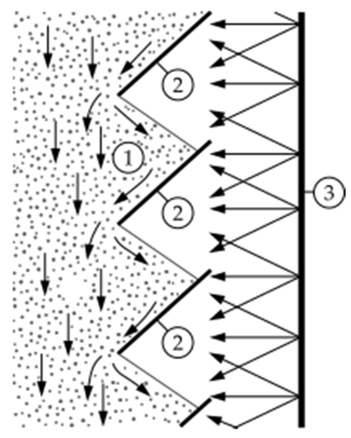
The scheme of the conceptual solution is shown in
Figure 1. The essence of the solution is as follows. When dispersed material is taken from the bottom of the sublimator, a material flow will form from top to bottom. In this case, a part of the bulk material, reaching the lower cut of the guide surface, will form an angle of repose, preventing particles from spilling through the upper cut below the guide surface. Wherein the angle of inclination of the guide surfaces should be large compared to the angle of repose of the particulate material. In such a case, when the material moves rheologically down the guide surfaces and reaches the bottom edge of the guide surface, the conveyed material again forms an angle of repose on the guide surface below. The latter is accompanied by a mixing of the material. At the same time, open areas of the material (slope surface) face directly to the heater and receive the heat flux in the form of radiation. Thanks to this, the most efficient heating of the bulk material is achieved.
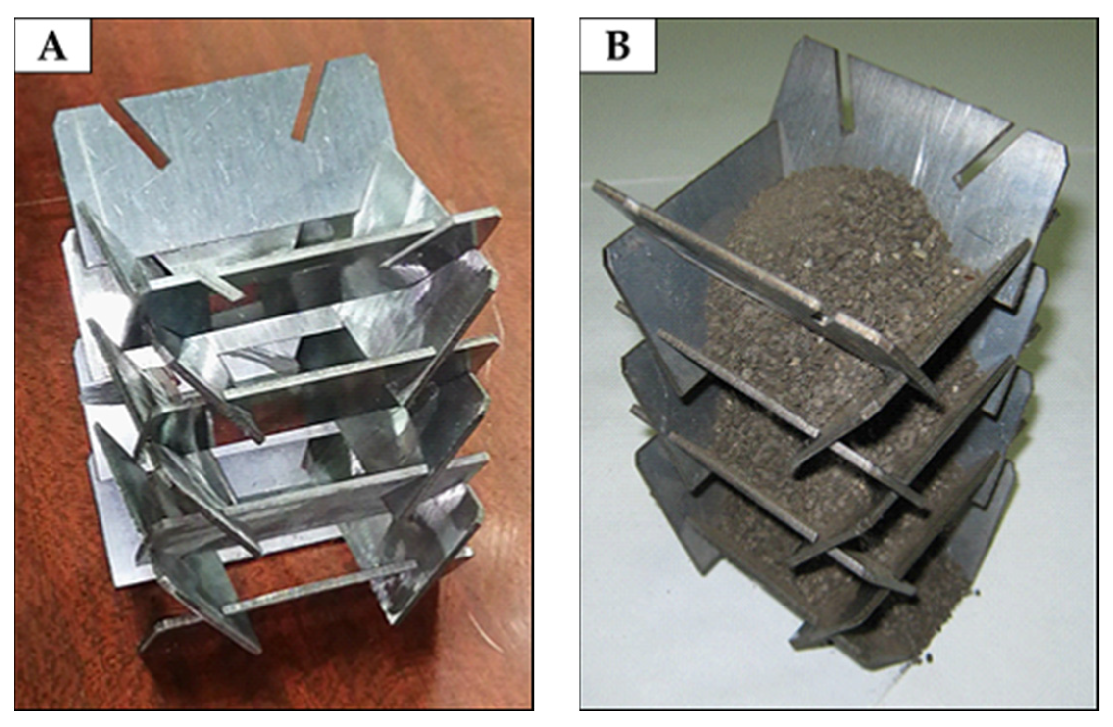
Technically, the solution is made in the form of a shaft formed in pairs by plates with inclined slots, the angle of which (to the horizon) is greater than the angle of repose of the bulk material (
Figure 2). In pairs, the plates form gaps between themselves and the lower pair of plates in such a way that the material pouring at the angle of repose does not “flow” against the upper edge of the plates located below.
2.2. Pilot Installation with Rheological Movement of Material
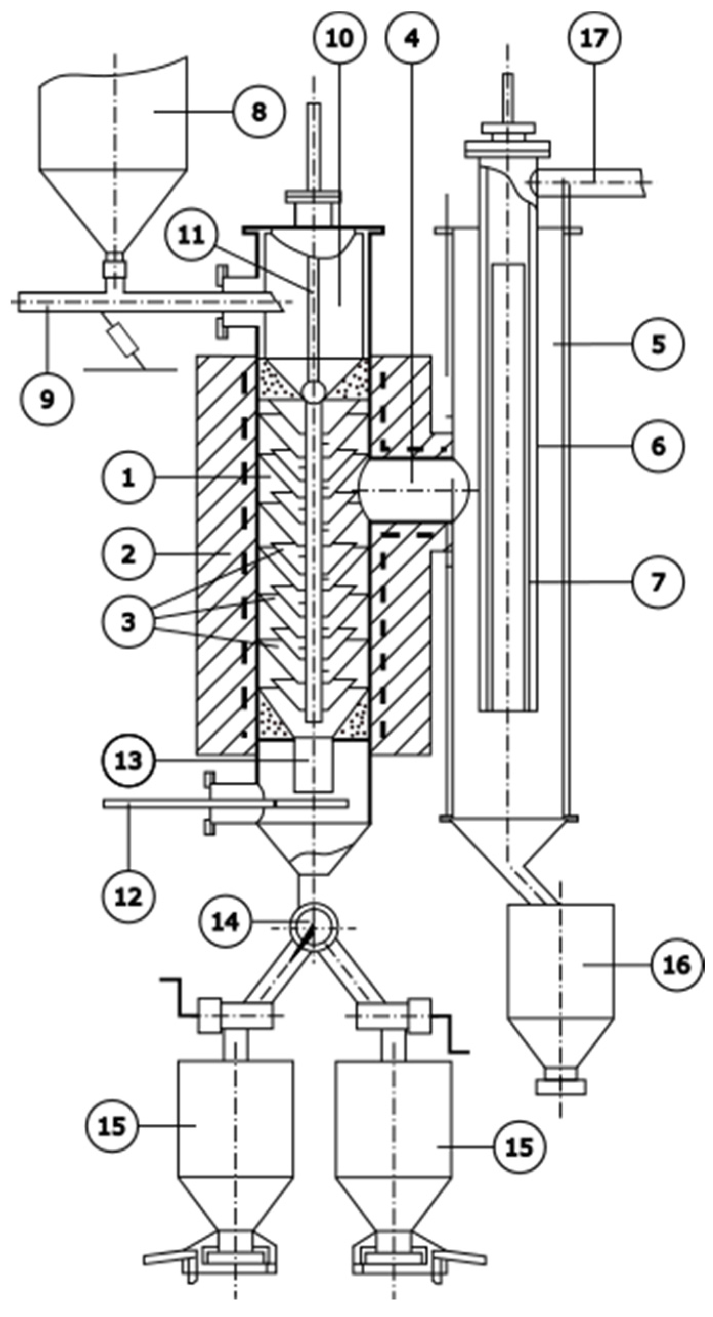
The pilot installation as a whole (
Figure 3) is a sublimator (1) heated by an electric furnace (2), inside which a shaft of inclined plates is placed (
Figure 2). At the first stage, to simplify the design, the sublimator body was used as a heater. The sublimator space is connected by a heated steam line (4) to a water-cooled condenser (5). Inside the condenser, a water-cooled pipe (6) is coaxially mounted, inside which a fabric filter (7) is placed to trap fine condensate.
The installation is equipped with a hopper (8) for feedstock and a vibrating feeder (9) for feeding the latter into an intermediate container (10). The intermediate container is separated from the sublimator space by a movable hollow rod with a conical shutter (11), inside which a thermocouple is placed. Below the shaft, assembled from plates, a vibrating unloader (12) is mounted. The latter, together with the bulk material at the mouth (13), forms a gate separating the unloading system, which prevents the penetration and condensation of the sulfide vapor phase in the residue bunkers. The unloading system consists of a processed material flow switch (14) and receiving hoppers (15) of the processing residue. Arsenic sulfides falling from the walls of the condenser were accumulated in a hopper (16). The gases from the apparatus were evacuated through the vacuum line (17). The temperature regimes in the reaction space of the sublimator were controlled automatically at set temperatures. At the same time, inertial temperature fluctuations inside the furnace space during the supply and disable of current loads were ±10–15 degrees.
A sublimator design such as this makes it possible to create apparatus for processing large volumes of raw materials by placing several vertical shafts and their variants from inclined surfaces, as well as a resistance heater(s) inside the reaction space. The capacity of such apparatus is 10 tons per day. One of the main advantages of the developed design is the possibility of manufacturing plates for inclined surfaces from ceramic materials that are inert with respect to the processed dispersed material and aggressive sulfur-containing steam environment. In addition, the absence of moving devices for moving the material greatly simplifies the process of sealing the apparatus.
2.3. The Operating Principle of the Installation
When carrying out the process of the sublimation of arsenic sulfides, the dispersed material from the feedstock bin was fed by means of a vibrating feeder into an intermediate container above the sublimator, from where the internal cavity of the shaft formed by the plates was filled. Heating of the processed material was carried out by radiation on the open areas of the surface formed by the dispersed material due to natural pouring and facing the external heater. The surface area for the vapor outlet (open surface areas) was about 5 × 10⁻² m2.
The processing time of bulk material (length of stay in the reaction space) was regulated by the performance of the vibratory unloader, the plane of which is located with a gap relative to the mouth.
The deterministic material was sent to the receiving hopper of the residue. When filling one of the receiving bins by means of a switch, the flow was directed to the second one. After cooling, the residue from sublimation was discharged from the hopper. The vapor phase from the sublimator was sent through a steam pipeline to solid-phase condensation of arsenic sulfides into a cyclone-type condenser. After its accumulation, the sulfide condensate was discharged into the condensate-receiving hopper.
2.4. Pre-Granulation of the Fine Concentrate
To reduce the removal of dust from the sublimator and reduce the diffusion resistance to the release of arsenic-containing vapor from the processed raw materials, the composite concentrates were previously subjected to granulation in a bowl granulator with the addition of about 2% sulfite-cellulose liquor. Granulation was carried out under the following conditions: bowl speed 0.5 s−1, tilt angle 0.7 radian. The granulation of concentrates also prevents disruption of the flow of the processed material along the inclined surfaces inside the sublimation shaft.
After granulation, the composite concentrate was dried at 100 °C to a residual moisture content of 1–3% and sieved. It was previously established that granule sizes up to 10 mm do not affect the degree of dearsenation of the material. Therefore, a fraction with a size of 1–10 mm was sent for processing, and fragments smaller than 1 mm were returned for granulation.
2.5. Materials
Technological tests to remove arsenic from gold-bearing composite concentrates were carried out with samples of gravity and flotation concentrates from the Bakyrchik deposit, the compositions of which are given in
Table 1.
When determining the granulometric composition, it was found that in the gravity concentrate more than 76% is represented by fractions from 0.063 to 1.6 mm, in the flotation concentrate—more than 90% by a fraction smaller than 0.043 mm.
2.6. Analytical Methods
The material composition was studied by X-ray fluorescence analysis using wave dispersive combined spectrometer Axios “PANalyical” (Amsterdam, Netherlands). The content of gold and silver in the products of processing was determined by assay analysis.
The D8 Advance “Bruker” X-ray diffractometer and Cu-Kα radiation, and the ICDDPDF-2 reference database (2020) were used to identify the phase composition.
Petrographic analysis was carried out on the LEICA DM2500 P optical polarization microscope (Leica Microsystems (Wetzlar, Germany)) and on the JEOL JXA-8230 electronic raster microanalyzer (JEOL, Japan).
3. Results
The conditions and results of the process of dearsenation of gold-bearing Bakyrchik composite concentrates without forced movement of the dispersed material in the sublimator are given in
Table 2 and
Table 3. In the same table, for comparison, similar data are given for previously performed technological tests on a vibro-vacuum installation with a capacity of 200 kg per day.
Due to the large amount of a priori information on the distribution of elements and compounds contained in composite concentrates, only the behavior of arsenic was monitored. To determine the effect of a vacuum on the degree of dearsenation of concentrates, tests were carried out at 92 kPa in an inert argon atmosphere to prevent arsenic oxidation. The specified pressure is atmospheric in the conditions of Almaty (Kazakhstan).
Analyzing the data given in
Table 2 and
Table 3 can be seen as follows. Arsenic under all conditions without forced movement of the granules in the sublimator is quite complete (more than 96–99%), both in vacuum and at 92 kPa, it passes into the vapor phase and, ultimately, into the sulfide condensate. The residual content of arsenic in the residue from sublimation at the same temperatures is 0.2–0.3% less than when moving with directional vibration. Such a difference is due, in our opinion, to a large rarefaction in the system, which contributes to the dissociation of loellingite. For the same reason, an insignificant difference was noted in the degree of arsenic transfer to the condensate at low (99.02–99.38%) and atmospheric pressure (96.17–97.38%). However, the use of low pressure in the system (vacuum) eliminates the oxidation of arsenic during the heating of the material and, therefore, eliminates the formation of highly toxic As
2O
3.
Dust entrainment during rheological movement of dispersed granular material decreased from 5.2 to 9.0% with vibrational movement of raw materials to 1–2% in our case. The amount of dust carried away from the reaction space during the processing of composite concentrates on the developed equipment was calculated from the content of SiO2 in the condensate.
The distribution of the main elements—sulfur and iron, in compounds with arsenic—as well as arsenic for products of vacuum thermal processing in technological tests on the developed equipment is given in
Table 4. The sublimation process of arsenic-containing compounds and arsenic were carried out for granular composite concentrates under the following conditions: gravity at a temperature of 700 ± 15 °C and a pressure of 2.3 kPa, flotation at 700 ± 15 °C and a pressure of 1.5 kPa. The size of the composite concentrate fraction in both cases was 1–8 mm.
When analyzing the results of the processing of gold–arsenic composite concentrates without their forced transfer to the volume of the sublimator, it can be seen that arsenic almost completely (by 96–99%) passes into the condensate and less than 1% remains in the residue from sublimation.
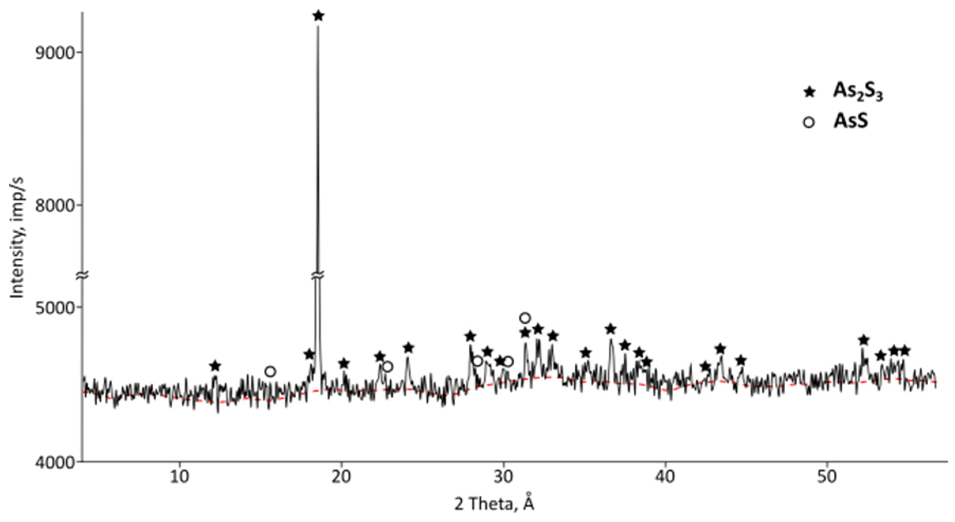
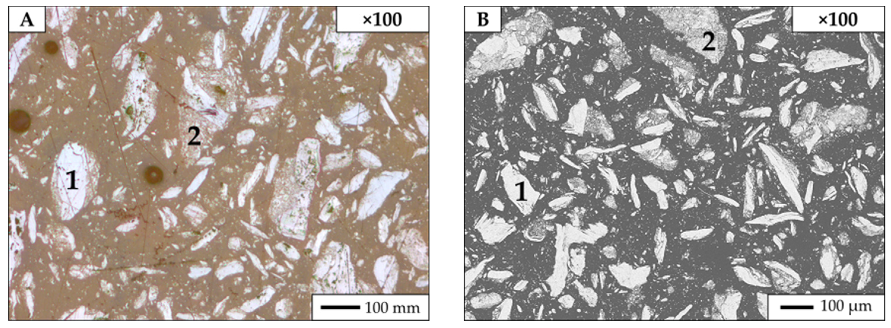
In the condensates, petrographic studies (
Figure 4) found sulfide compounds of arsenic and grains of elemental arsenic. X-ray phase analysis (
Figure 5) of condensates revealed the presence of orpiment (As
2S) and realgar (AsS). That is, the condensate is represented by the safest forms of arsenic, which can be melted into ingots that are convenient for burial or storage.
The content of precious metals in the condensate was not detected by chemical analysis, less than 1 g/t of gold was found by assay analysis. That is, precious metals almost completely remain in the residue from sublimation with the lowest possible content of arsenic.
4. Discussion
Because arsenic prevents the extraction of gold, a lot of work has been devoted to the development of highly efficient dearsenation technologies for this kind of gold–arsenic concentrate. A detailed analysis of the existing technologies is given in [
52]. The main disadvantages of raw material processing in these schemes are the insufficient extraction of gold into the final product, low rates of arsenic extraction, their multi-stage and resource-intensive nature, and the need to organize special burial grounds for the disposal of arsenic waste. In this regard, the extraction of arsenic by vacuum thermal sublimation at moderate temperatures with condensation of it in the sulfide or elemental form is preferred. Some of the advantages of this technology over others are its operation without a reagent, environmental safety, high rates of arsenic extraction, and almost complete concentration of all precious metals in the sublimation residue.
The vacuum method for processing arsenic-containing raw materials and the equipment for its practical implementation must meet several technological and environmental requirements. At the same time, it is necessary to ensure the deepest removal of arsenic, the minimum formation of dust, to exclude circulation loads on the process, to create conditions for the most comprehensive condensation of arsenic vapors with a minimum content of precious metals in sublimates, and to prevent the formation of arsenic oxide and its emission into the environment.
In addition, vacuum equipment should provide not only tightness, which excludes the release of toxic compounds into the environment, but also the continuity of transportation of dispersed raw materials through the thermal vacuum treatment zone. The equipment must have adjustable loading of material and unloading of cinder and high thermal performance, at which the required performance is achieved. Also, the equipment must be equipped with effective systems for cleaning dust from the gas and the condensation of arsenic-containing vapors. It should be borne in mind that the use of rotating and rubbing devices under vacuum and abrasive dispersed media is undesirable due to their rapid failure. Fluidization with gas is characterized by high entrainment of dust and requires powerful dust collection and pumping systems. And, as practice has shown, the use of directed vibrations for the movement of material through the zone of thermal vacuum processing is accompanied by corrosion and deformation of the vibrating column.
Therefore, it was decided to develop equipment in which the movement of material in a sublimation furnace is carried out due to the rheological properties of the material. The use of the proposed equipment solves the problems of thermal and corrosion resistance of special steels used in the creation of vacuum apparatuses, including vibro-vacuum furnaces. This technological solution to a large extent allows extending the service life of expensive vacuum furnaces, as well as using materials that are inert to the sulfide environment. We have not found analogs of such equipment. All technical solutions have patents from the Republic of Kazakhstan [
53,
54,
55,
56].
To confirm the high efficiency of the equipment, we carried out comparative technological tests for arsenic extraction from the concentrates of the Bakyrchik deposit (Kazakhstan). The results showed as follows: When using equipment with rheological movement, a higher degree of arsenic removal (>99%) is achieved compared to an apparatus in which material movement is ensured by directional vibrations (97–98%). This effect is facilitated by a more complete decomposition of Fe2As due to lower pressure in the sublimator and due to direct radiation heating of the open surface of the processed material. The question of the complete decomposition of iron semi-arsenide into elemental arsenic and iron remains open. It is known that even at temperatures above 1200 °C, Fe2As is present in processing residues. Therefore, increasing the degree of arsenic sublimation by increasing the temperature is not rational, because this will lead to an increase in energy consumption and the use of more expensive structural materials.
During the dearsenation process on the new equipment, corrosion of the steel inclined surfaces that make up the shaft through which the material is transported was also noted. Worn plates were replaced with new ones in a short time, eliminating long equipment downtime. Therefore, the main advantage of the proposed design of the electric sublimation furnace is its simplicity. This is one of the most important aspects when using equipment on an industrial scale.
The condensate can be remelted into blocks convenient for transportation and disposal. This process was previously tested [
57], where ingots of approximately 3750 kg/m
3 density were produced by melting in a crucible furnace under a vacuum of 4–6 kPa and a specific cooling rate of the melt (around 20 °C/min).
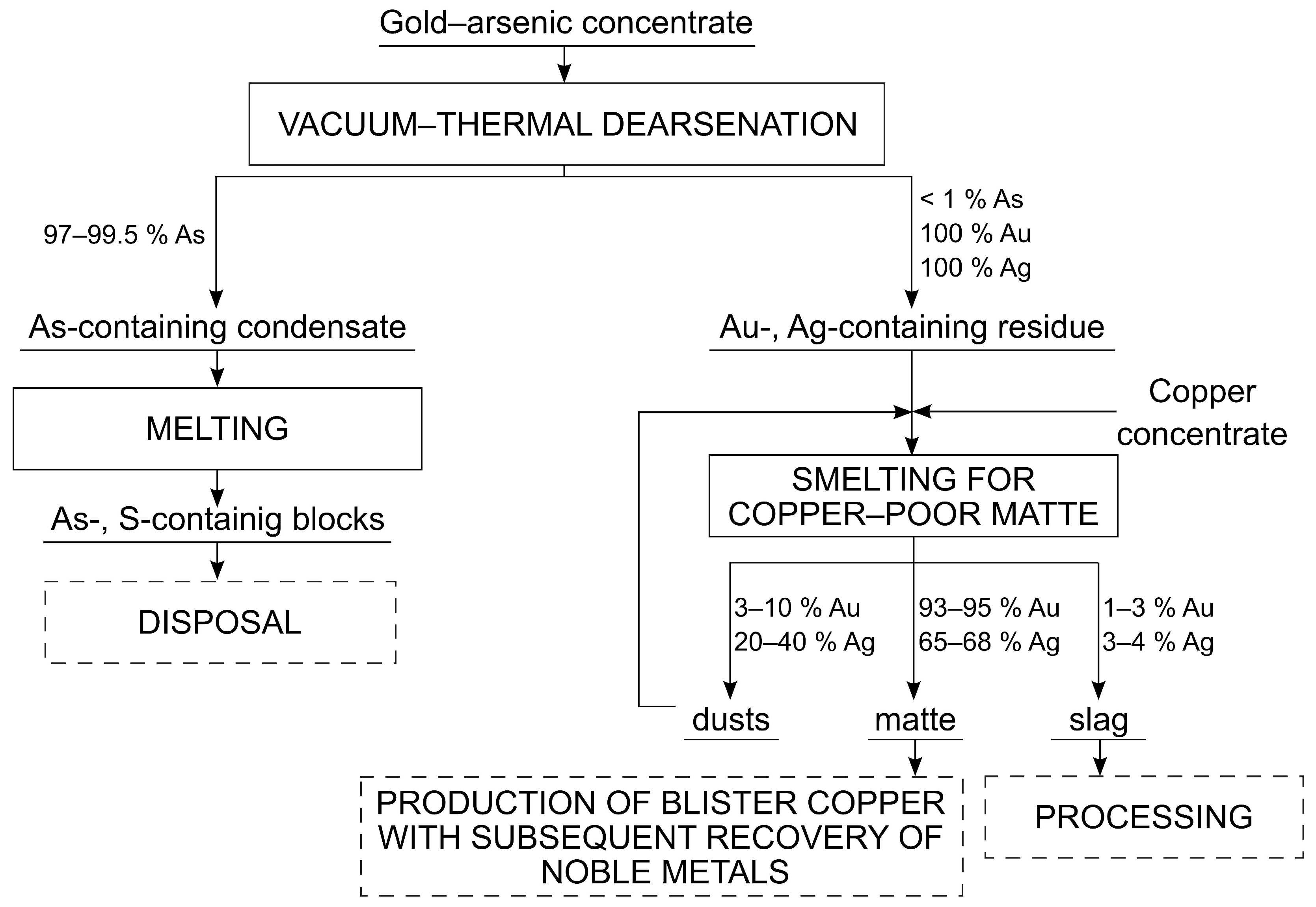
Copper is known to be a material that is good for collecting gold. Therefore, the obtained residues from vacuum thermal processing, containing noble metals, are proposed to be melted into copper-poor mattes [
52]. This is due to the fact that gold recovery did not exceed 65–67% during direct cyanidation [
58] and thiocarbamide leaching [
59] of residues after vacuum processing of refractory gold–arsenic concentrates. Most of the gold (93.72 and 93.92%) and most of the silver (65.74 and 67.98%) are concentrated in the matte after melting into copper-poor mattes. The received matte can then be put through a converting process to obtain blister copper exposed to electrolytic refinement with the recovery of gold from sludge according to the offered scheme (
Figure 6).
5. Conclusions
Analyzing the conducted technological tests for the dearsenation of gold–arsenic composite concentrates and the functioning of the developed sublimation equipment, we can state a high degree (more than 96–99%) of sublimation of arsenic from the material with almost complete localization of precious metals in the sublimation residue and stable operation of the equipment that provides the technological process. Stagnant zones in the mine with dispersed material were not found.
A slight difference in the degree of transfer of arsenic into condensate was noted at low (99.02–99.38%) and atmospheric pressure (96.17–97.38%). However, the use of low pressure in the system (vacuum) eliminates the oxidation of arsenic during the heating of the material and therefore eliminates the formation of highly toxic As2O3.
The remainder, containing less than 1% arsenic, can be processed by known methods. Condensate, represented by the safest forms of arsenic, can be melted down into ingots that are convenient for burial or storage.
The proposed technical solution for the design of the process of sublimation of arsenic sulfides from gold–arsenic composite concentrates allows for the scaling up of the processing of this kind of raw material and simplifies the choice of materials for the structural design of the process.
Author Contributions
Conceptualization, S.T.; methodology, S.T., V.V. and O.K.; investigation, A.N., X.L. and E.K.; data curation, S.T. and V.V.; writing—original draft preparation, S.T. and V.V.; writing—review and editing, S.T., A.N. and Y.L.; visualization, A.N., X.L., O.K. and Y.L.; project administration, S.T. and O.K. All authors have read and agreed to the published version of the manuscript.
Funding
This research was funded by the Science Committee of the Ministry of Science and Higher Education of the Republic of Kazakhstan, grant number AP09258805.
Data Availability Statement
The data used to support the findings of this study are included within the article.
Conflicts of Interest
The authors declare no conflict of interest.
References
- Genkin, A.D.; Bortnikov, N.S.; Cabri, L.J.; Wagner, F.E.; Stanley, C.J.; Safonov, Y.G.; McMahon, G.; Friedl, J.; Kerzin, A.L.; Gamyanin, G.N. A multidisciplinary study of invisible gold in arsenopyrite from four mesothermal gold deposits in Siberia, Russian Federation. Econ. Geol. 1998, 93, 463–487. [Google Scholar] [CrossRef]
- Koizhanova, A.K.; Magomedov, D.R.; Tastanov, E.A.; Kenzhaliyev, B.K.; Sedelnikova, G.V.; Berkinbayeva, A.N. Intensification of copper leaching from heaps using biological oxidation. Metalurgija 2022, 61, 789–792. [Google Scholar]
- Koizhanova, A.K.; Berkinbayeva, A.N.; Sedelnikova, G.V.; Kenzhaliyev, B.K.; Azlan, M.N.; Magomedov, D.R.; Efremova, Y.M. Research of biochemical gold recovery methodusing high-arsenic raw materials. Metalurgija 2021, 60, 423–426. [Google Scholar]
- Yaozhong, L.; Smith, R.W. Arsenic removal from high arsenic bearing gold sulphide concentrate. Mineral. Proc. Extrac. Metal. 2004, 113, 189–191. [Google Scholar] [CrossRef]
- Curreli, L.; Garbarino, C.; Ghiani, M.; Orrù, G. Arsenic leaching from a gold bearing enargite flotation concentrate. Hydrometallurgy 2009, 96, 258–263. [Google Scholar] [CrossRef]
- Khrapunov, V.E.; Kenzhaliev, B.K.; Bolotova, L.S.; Isakova, R.A. Gold extraction from persistent arsenic-containing concentrates. Tsvetnye Metally 2001, 11, 33–36. [Google Scholar]
- Kozhakhmetov, S.M.; Kvyatkovskiy, S.A.; Ospanov, Y.A.; Semenova, A.S. Pyrometallurgical opening of refractory carbonaceous and arsenic gold ledge ores with noble metal recovery to matte. Tsvetnye Metally 2017, 8, 39–42. [Google Scholar] [CrossRef]
- Kozhakhmetov, S.M.; Kvyatkovskiy, S.A. Reducing pyrometallurgical selection of particularly refractory ledge gold ore. Eurasian Chem. Technol. J. 2017, 19, 71–80. [Google Scholar] [CrossRef]
- Toktar, G.; Koizhanova, A.; Magomedov, D.; Abdyldaev, N.; Bakrayeva, A. Increased recovery of free fine gold in the leaching process. Kompleks. Ispolz. Mineral. Syra 2022, 322, 51–58. [Google Scholar] [CrossRef]
- Kim, B.; Park, C.; Cho, K.; Kim, J.; Choi, N.; Lee, S. Sulfuric acid baking-water leaching for gold enrichment and arsenic removal from gold concentrate. Minerals 2021, 11, 1332. [Google Scholar] [CrossRef]
- Karimov, K.; Rogozhnikov, D.; Kuzas, E.; Dizer, O.; Golovkin, D.; Tretiak, M. Deposition of arsenic from nitric acid leaching solutions of gold-arsenic sulphide concentrates. Metals 2021, 11, 889. [Google Scholar] [CrossRef]
- Dunn, J.G.; Chamberlain, A.C. The recovery of gold from refractory arsenopyrite concentrates by pyrolysis-oxidation. Miner. Eng. 1997, 10, 919–928. [Google Scholar] [CrossRef]
- Seitkan, A.; Redfren, S.A. Arsenic in refractory gold ore processing. Kompleks. Ispolz. Mineral. Syra 2021, 317, 5–13. [Google Scholar] [CrossRef]
- Zemskova, L.; Shlyk, D.; Barinov, N. Hybrid sorbents for removal of arsenic. Kompleks. Ispolz. Mineral. Syra 2022, 320, 32–41. [Google Scholar] [CrossRef]
- Kolesnikova, O.; Syrlybekkyzy, S.; Fediuk, R.; Yerzhanov, A.; Nadirov, R.; Utelbayeva, A.; Agabekova, A.; Latypova, M.; Chepelyan, L.; Volokitina, I.; et al. Thermodynamic simulation of environmental and population protection by utilization of technogenic tailings of enrichment. Materials 2022, 15, 6980. [Google Scholar] [CrossRef] [PubMed]
- Zhangabay, N.; Sapargaliyeva, B.; Utelbayeva, A.; Kolesnikov, A.; Aldiyarov, Z.; Dossybekov, S.; Esimov, E.; Duissenbekov, B.; Fediuk, R.; Vatin, N.I.; et al. Experimental analysis of the stress state of a prestressed cylindrical shell with various structural parameters. Materials 2022, 15, 4996. [Google Scholar] [CrossRef]
- Kolesnikov, A.S. Thermodynamic simulation of silicon and iron reduction and zinc and lead distillation in zincoligonite ore-carbon systems. Russ. J. Non-Ferr. Met. 2014, 55, 513–518. [Google Scholar] [CrossRef]
- Vasilyeva, N.; Fediuk, R.; Kolesnikov, A. Hardening of bimetallic wires from secondary materials used in the construction of power lines. Materials 2022, 15, 3975. [Google Scholar] [CrossRef]
- Kolesnikova, O.; Vasilyeva, N.; Kolesnikov, A.; Zolkin, A. Optimization of raw mix using technogenic waste to produce cement clinker. Min. Inf. Anal. Bull. 2022, 60, 103–115. [Google Scholar] [CrossRef]
- Klyuev, S.V.; Klyuev, A.V.; Khezhev, T.A.; Pukharenko, Y.V. Technogenic sands as effective filler for fine-grained fibre concrete. J. Phys. Conf. Ser. 2018, 1118, 012020. [Google Scholar] [CrossRef]
- Volokitin, A.; Naizabekov, A.; Volokitina, I.; Kolesnikov, A. Changes in microstructure and properties of austenitic steel AISi 316 during high-pressure torsion. J. Chem. Technol. Metallur. 2022, 57, 809–815. [Google Scholar]
- Donayev, A.; Kolesnikov, A.; Shapalov, S.; Sapargaliyeva, B.; Ivakhniyuk, G. Studies of waste from the mining and metallurgical industry, with the determination of its impact on the life of the population. News Natl. Acad. Sci. Repub. Kazakhstan Ser. Geol. Tech. Sci. 2022, 4, 55–68. [Google Scholar] [CrossRef]
- Zheng, Y.; Wei, D.; Liu, W.; Duan, H.; Zhou, S. One Novel two-step bio-oxidation pretreatment of arsenic-containing gold-bearing concentrate. Int. J. Electrochem. Sci. 2018, 13, 5983–5994. [Google Scholar] [CrossRef]
- Gurman, M.A.; Shcherbak, L.I.; Rasskazov, A.V. Gold and arsenic recovery from calcinates of rebellious pyrite-arsenopyrite concentrates. J. Min. Sci. 2015, 51, 586–590. [Google Scholar] [CrossRef]
- Mesa Espitia, S.L.; Lapidus, G.T. Arsenic removal strategy in the processing of an arsenopyritic refractory gold ore. Hydrometallurgy 2021, 203, 105628. [Google Scholar] [CrossRef]
- Rakhmanov, O.B.; Aksenov, A.V.; Mineev, G.G.; Nazarov, K.M.; Karimov, M.I. Processing of refractory gold-arsenic flotation concentrate of Ikkijelon deposit by pressure oxidation. iPolytech J. 2018, 22, 163–172. [Google Scholar] [CrossRef]
- Cho, K.; Kim, H.; Myung, E.; Purev, O.; Choi, N.; Park, C. Recovery of gold from the refractory gold concentrate using microwave assisted leaching. Metals 2020, 10, 571. [Google Scholar] [CrossRef]
- Isabaev, S.M.; Kuzgibekova, H.M.; Zhinova, E.V.; Zikanova, T.A. Development of technology for oxidative roasting of gold-arsenic concentrates of double resistance. Kompleks. Ispolz. Mineral. Syra 2015, 311, 27–31. [Google Scholar]
- Qin, H.; Guo, X.; Tian, Q.; Uu, D.; Zhang, L. Recovery of gold from sulfide refractory gold ore: Oxidation roasting pretreatment and gold extraction. Miner. Eng. 2021, 164, 106822. [Google Scholar] [CrossRef]
- Zhang, H.; Wang, Y.; He, Y.; Xu, S.; Hu, B.; Gao, H.; Zheng, G. Efficient and safe disposition of arsenic by incorporation in smelting slag through copper flash smelting process. Miner. Eng. 2021, 160, 106661. [Google Scholar] [CrossRef]
- Paleev, P.L.; Gulyashinov, A.N.; Antropova, I.G.; Gulyashinov, P.A. Extraction of gold from refractory arsenopyrite ores and concentrate. Gold Technol. 2013, 2, 36–38. [Google Scholar]
- Paleev, P.L.; Gulyashinov, A.N.; Antropova, I.G. Dearsenation of gold-bearing arsenopyrite ore in atmosphere of superheated water vapor. Phys. Tech. Probl. Min. 2013, 6, 175–179. [Google Scholar]
- Paleev, P.L.; Gulyashinov, P.A.; Gulyashinov, A.N.; Antropova, I.G. Roasting of gold-bearing arsenopyrite ore in an atmosphere of superheated steam. Int. J. Appl. Fundam. Res. 2017, 12, 233–237. [Google Scholar]
- Chelokhsaev, L.S.; Isakova, R.A.; Tarasenko, B.Z. Pilot tests of vacuum-thermal separation of arsenic from gold-bearing flotation concentrates. Tsvetnye Metally 1980, 9, 25–27. [Google Scholar]
- Khrapunov, V.E.; Isakova, R.A.; Fudulov, I.O. Laboratory study of vacuum-thermal processing of gold-arsenic concentrate of the People’s Republic of China. Kompleks. Ispolz. Mineral. Syra 1991, 11, 55–59. [Google Scholar]
- Khrapunov, V.E.; Chelokhsaev, L.S.; Isakova, R.A. Composition and purification of exhaust gases of the process of vacuum-thermal processing of gold-arsenic concentrates. Tsvetnye Metally 1992, 12, 53–55. [Google Scholar]
- Khrapunov, V.E.; Isakova, R.A.; Chelokhsaev, L.S. Isolation of arsenic from gold-bearing concentrates of Central Asia by vacuum thermal sublimation. Kompleks. Ispolz. Mineral. Syra 1992, 12, 53–55. [Google Scholar]
- Khrapunov, V.E.; Isakova, R.A.; Chelokhsaev, L.S. About vacuum processing of gold-arsenic concentrates of Yakutia. Tsvetnye Metally 1993, 4, 9–12. [Google Scholar]
- Khrapunov, V.E. Vacuum thermal sublimation of arsenic from gold arsenic-, antimony-, copper-containing concentrates. Ind. Kazakhstan 2001, 6, 82–83. [Google Scholar]
- Khrapunov, V.E.; Isakova, R.A. Processing of Refractory Gold-Arsenic Concentrates Using Vacuum; Gylym: Almaty, Kazakhstan, 2002; 252p. [Google Scholar]
- Volodin, V.N.; Trebukhov, S.A.; Nitsenko, A.V.; Trebukhov, S.A.; Tuletay, F.K. Some problems of processing dispersed arsenic-coating raw materials by sublimation in vacuum. J. Phys. Conf. Ser. 2021, 2059, 012026. [Google Scholar] [CrossRef]
- Calculation of Heat Transfer by Radiation. Calculation of the Heat Flux Transferred from the Heater Surface to the Heated Surface Using Radiant Heat Transfer. Available online: http://www.nomogramka.info>heat>radiation (accessed on 26 January 2023).
- Steel 50 (50A). Structural Carbon Quality. Available online: https://enginiger.ru>harakterristiki-i-svojstva (accessed on 17 January 2023).
- Kanaeva, Z.K.; Kanaeva, A.T.; Semenchenko, G.V. Geological structure of the gold-arsenic Bakyrchikdeposit of East Kazakhstan. Fundam. Res. 2014, 11, 2405–2410. [Google Scholar]
- Novoselova, A.V.; Pashinkin, A.S. Vapor Pressure of Volatile Metal Chalcogenides; Nauka: Moscow, Russia, 1978; p. 112. [Google Scholar]
- Pashinkin, A.S.; Fedorov, V.A.; Zviadadze, G.N.; Malkova, A.S.; Izergin, A.P.; Izergin, A.A.; Generalova, S.A.; Dzhaparidze, O.I.; Gelovani, L.A. Arsenopyrite dissociation pressure and the study of the Fe–As–S. J. App. Chem. 1979, 5, 1085–1091. [Google Scholar]
- Khrapunov, V.E.; Spivak, M.M.; Spitsyn, V.A.; Khlystov, A.S.; Isakova, R.A.; Fedulov, I.O. On the thermal behavior of arsenopyrite. J. Inorg. Chem. 1991, 36, 2786–2790. [Google Scholar]
- Khrapunov, V.E.; Isakova, R.A.; Spivak, M.M.; Fudulov, I.O. Dissociation of irondiarsenide. Inorg. Chem. 1993, 8, 784–785. [Google Scholar]
- Tkach, M.A.; Tkachenko, O.B.; Isakova, R.A.; Ugryumova, L.E. On the behavior of iron arsenidesduring heated in vacuum. Proc. Inst. Metall. Ore Benef. 1977, 52, 54–60. [Google Scholar]
- Münster, A. Classical Thermodynamics: Germany; Wiley-Interscience: London, UK, 1970; 387p. [Google Scholar]
- Volodin, V.N.; Trebukhov, S.A.; Nitsenko, A.V.; Trebukhov, A.A.; Kilibayev, E.O. Vacuum sublimators with a rheological displacement of the dispersed medium. Kompleks. Ispolz. Mineral. Syra 2023, 324, 57–63. [Google Scholar] [CrossRef]
- Volodin, V.; Trebukhov, S.; Nitsenko, A.; Linnik, X.; Tuleutay, F.; Trebukhiv, A.; Ruzakhunova, G. Pyrometallurgical scheme intended to process arsenic-containing concentrates with recovery of precious metals. Metals 2023, 13, 540. [Google Scholar] [CrossRef]
- Trebukhov, S.A.; Volodin, V.N.; Kenzhaliyev, B.K.; Ulanova, O.V.; Nitsenko, A.V.; Trebukhov, A.A.; Tuleutay, F.K. Vacuum Apparatus for Processing of Bulk Materials. Patent of the Republic of Kazakhstan 36013, 23 December 2022. Available online: https://gosreestr.kazpatent.kz/Invention/Details?docNumber=350356 (accessed on 11 June 2023).
- Volodin, V.N.; Trebukhov, S.A.; Kenzhaliyev, B.K.; Nitsenko, A.V.; Burabayeva, N.M.; Trebukhov, A.A.; Tuleutay, F.K. Vacuum Apparatus for Processing of Bulk Materials. Patent of the Republic of Kazakhstan 36102, 24 Febrary 2023. Available online: https://gosreestr.kazpatent.kz/Invention/Details?docNumber=352318 (accessed on 11 June 2023).
- Volodin, V.N.; Trebukhov, S.A.; Kenzhaliyev, B.K.; Nitsenko, A.V.; Burabayeva, N.M.; Trebukhov, A.A.; Tuleutay, F.K. Vacuum Apparatus for Processing of Bulk Materials. Patent of the Republic of Kazakhstan 36118, 24 February 2023. Available online: https://gosreestr.kazpatent.kz/Invention/Details?docNumber=352568 (accessed on 11 June 2023).
- Volodin, V.N.; Trebukhov, S.A.; Kenzhaliyev, B.K.; Nitsenko, A.V.; Burabayeva, N.M.; Trebukhov, A.A.; Tuleutay, F.K. Vacuum Sublimation Furnace for Processing of Bulk Materials. Patent of the Republic of Kazakhstan 36160, 7 April 2023. Available online: https://gosreestr.kazpatent.kz/Invention/Details?docNumber=354673 (accessed on 11 June 2023).
- Khrapunov, V.E.; Chelokhsaev, L.S.; Issakova, R.A. Compacting of sulfide arsenic-containing waste. Kompleks. Ispolz. Mineral. Syra 2000, 3–4, 84–88. [Google Scholar]
- Tkachenko, O.B.; Ganzha, T.I.; Morozova, T.P. Processing of gold-arsenic-coal concentrates. Tsvet. Metall. 1972, 10, 20–23. [Google Scholar]
- Isakova, R.A.; Lodeyshchikov, V.V.; Chelokhsayev, L.S. Gold recovery from cinders of evacuation of sulfide arsenic-containing concentrates. Kompleks. Ispolz. Mineral. Syra 1989, 7, 39–42. [Google Scholar]
- Trebukhov, S.A.; Volodin, V.N.; Nitsenko, A.V.; Linnik, X.A.; Kassenova, B.A. Arsenic vapor condensation in the vacuum-thermal dearsenation process of gold concentrate. Min. Process. Extr. Metall. Rev. 2023, 1–12. [Google Scholar] [CrossRef]
| Disclaimer/Publisher’s Note: The statements, opinions and data contained in all publications are solely those of the individual author(s) and contributor(s) and not of MDPI and/or the editor(s). MDPI and/or the editor(s) disclaim responsibility for any injury to people or property resulting from any ideas, methods, instructions or products referred to in the content. |
© 2023 by the authors. Licensee MDPI, Basel, Switzerland. This article is an open access article distributed under the terms and conditions of the Creative Commons Attribution (CC BY) license (https://creativecommons.org/licenses/by/4.0/).


 ,
, 


