1. Introduction
In situ automated fiber placement (AFP) has made significant progress in recent years as an economical alternative for the production of thermoplastic composites. Laser-assisted consolidation of the carbon fiber reinforced polymer (CFRP) prepregs eliminates the need for post-consolidation and thus reduces production time and cost. By using a six degree-of-freedom (DOF) robotic arm, complex parts can be realized. Further, this system enables the automation and up-scaling of the process. High-performance polymers, like polyaryletherketone (PAEK), allow for the use of AFP in structures for aerospace applications [
1,
2].
A substantial part of the cost of manufacturing composite parts is the production of a tooling [
3]. The current industry standard is a metallic mold due to its ability to be heated above the glass-transition temperature of all polymers. However, metal as a mold material results in high production costs and a long production time. An additional disadvantage of metallic molds is their inability to hold the first ply of a laminate in its correct position since no bond between those two can be formed. Thus, in most cases, a polymer film is applied to the metallic mold. Polyimide is commonly used. Another approach to overcome the problem of holding the first ply in the mold in its correct position is the coating of the mold’s surface with polyetheretherketone (PEEK) or manufacturing the entire mold out of PEEK [
4].
There is a growing body of research focused on additively manufactured molds for composite manufacturing with the goal of reducing the costs and time for the manufacturing process [
4,
5,
6,
7,
8]. The majority of those studies, however, are only applicable to thermosetting composites. This work aims to address this research gap by investigating the use of a thermoplastic to additively manufacture molds for AFP of LM-PAEK. Polyamide 6 (PA6) is used as the mold material because of its mechanical characteristics and incompatibility with LM-PAEK. The goal is the formation of a bond that is strong enough to hold a laminate in the mold during the manufacturing process while still allowing for the demolding of the laminate after its completion.
The bonding mechanism can be divided as follows:
High-Temperature (HT) Bonding: The bonding of a PAEK and PA6 with a temperature above the melting temperature of both polymers.
Low-Temperature (LT) Bonding: The bonding of a PAEK and PA6 with a temperature above the melting temperature of PA6 and below that of PAEK.
In this study, the low-temperature bonding of a PAEK with PA6 is investigated. While little is known about the specific bonding of a PAEK and PA6, research on the bonding of immiscible polymers has been conducted for years. Smiley et al. [
9] investigated the bonding of thermoplastic composites by using an interlayer polymer film composed of a different but compatible polymer compared to the matrix of the composite. A film of polyetherimide (PEI) was consolidated onto a polyetheretherketone (PEEK) composite laminate. While bringing two of those laminates together under force, the parts were heated above the melting temperature of PEI and below that of PEEK. This allowed for a sufficient wet-out of the laminates’ surfaces and thus molecular diffusion. A low viscosity of the polymer at the interface and thus sufficient adhesion are crucial for the bonding strength, which was also a finding of Kumar et al. [
10]. The bonding of non-miscible polymers has also been described by Smiley et al. [
9]. The bond strength was found to be reliant on the migration of the reinforcing fibers of the composite into the interlayer polymer. Further investigations on the bonding of incompatible polymers were conducted by Löhner et al. [
11]. Two thermoplastic polymers were bonded using rotational molding. The bond was based on mechanical adhesion and interlayer form closures between the two polymers [
11].
Amend et al. [
12] used a 1064 nm laser for the bonding of a thermoset and a thermoplastic polymer. It was concluded that the laser can damage fibers in the composite and lead to matrix residuals on the surface, which create undercuts. This results in an enlarged bonding surface and thus higher bonding strength. This may be applicable to the laser-assisted bonding of incompatible thermoplastic polymers.
To determine the suitability of PA6 as a mold material for the AFP of LM-PAEK, this study investigates the interlayer as well as the mechanical characteristics of the bond.
2. Materials and Methods
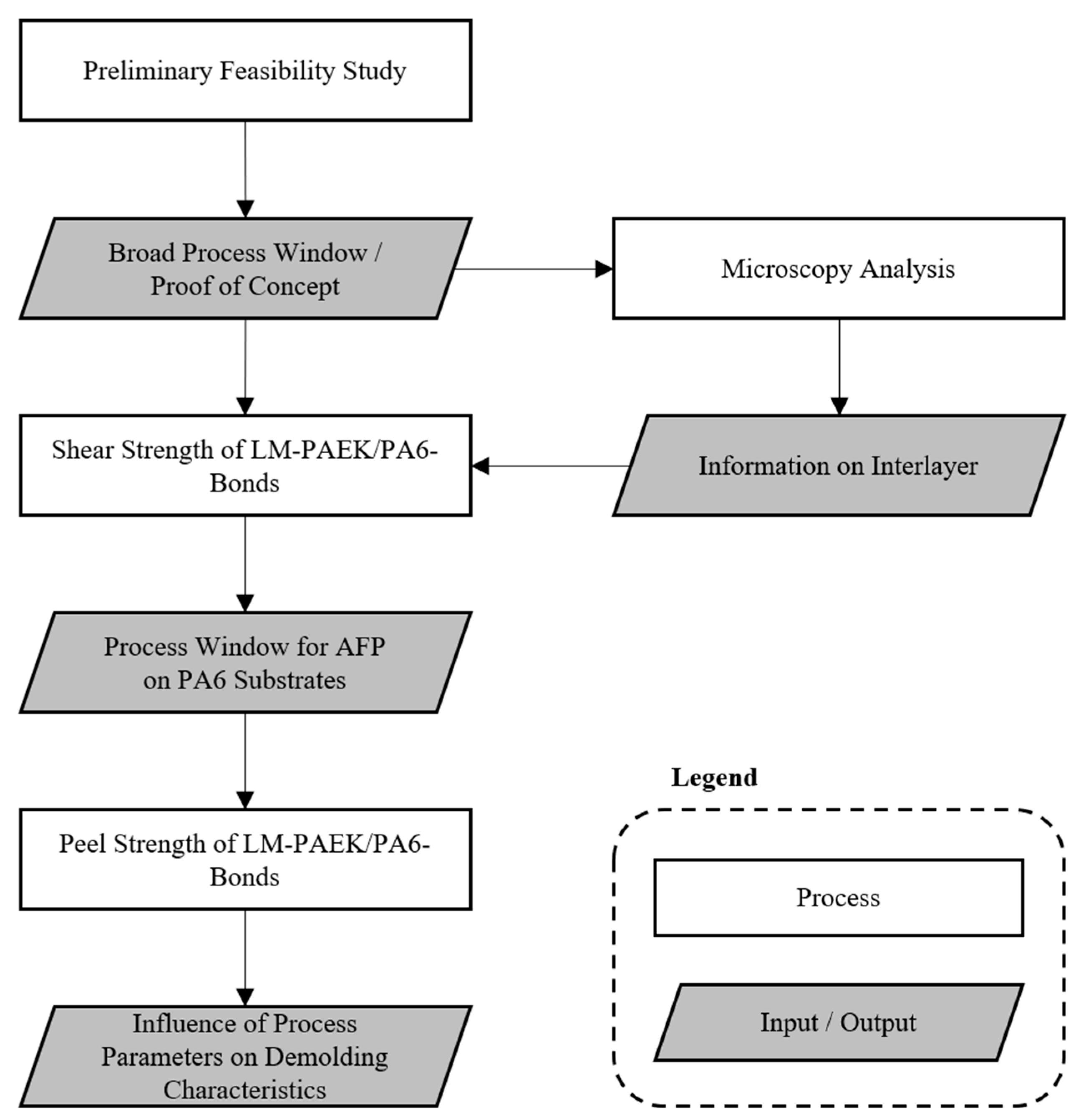
The basic structure of this study is shown in
Figure 1. A preliminary feasibility study was conducted to determine the parameters that needed adjustment for AFP to be usable for the bonding of LM-PAEK tapes onto PA6 substrates. Microscopy analysis was used to obtain information on the morphological characteristics of the interlayer between the two polymers. To determine the general process window in which a bonding of the two polymers can be achieved, double lap shear (DLS) tests were performed. The parameters investigated in this study were the laser focus adjustment, process temperature and consolidation pressure. In the next step, peel tests were performed to further investigate the impact of the process parameters on demolding characteristics.
2.1. Materials
For the AFP process, the thermoplastic prepreg Cetex TC 1225 was used. These tapes have a low-melting PAEK (LM-PAEK) as a matrix material and are reinforced with standard modulus carbon fibers. The prepreg has a tensile strength of 2410 MPa in the direction of the fibers and a tensile modulus of 135 GPa. Further relevant properties of the prepreg are listed in
Table 1.
As a substrate for the DLS tests, casted PA6 purchased through BW Kunststoffe e.K (Heilbronn, Germany) was used. The material has a thickness of 3 mm and was dyed black to reduce the reflection of the laser during the AFP process. The melting temperature of the PA6 is 216 °C [
13].
For the peel tests, a 3D-printed substrate was used to determine the demolding characteristics. The substrates were 3D printed out of a short carbon fiber reinforced PA6 granulate Akromid B3 ICF 30 AM purchased from Akroplastic (Niederzissen, Germany), which has a melting point of 220 °C.
The granulate as well as the casted PA6 sheets were dried for 3 h at 40 °C.
2.2. Manufacturing Facilities
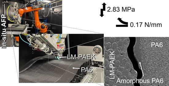
The AFP facility at the German Aerospace Center (DLR) in Stuttgart, Germany was used for this study and can be observed in
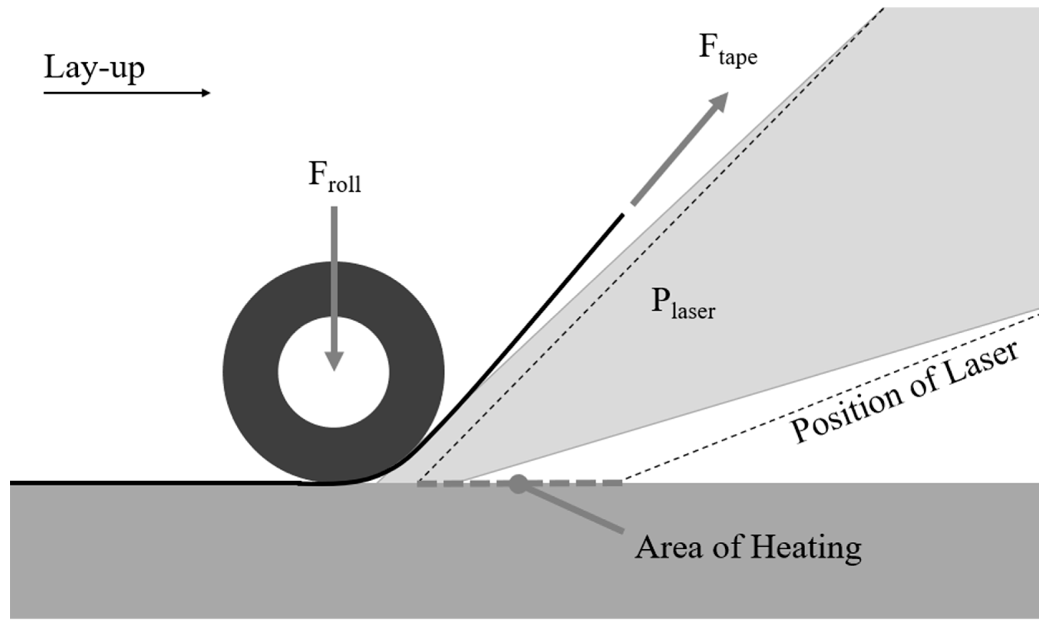
Figure 2. The facility consists of a 6-DOF robotic arm KR210 produced by the company KUKA AG (Augsburg, Germany). The endeffector of the arm is a multi-tape laying head (MTLH) produced by AFPT (Dörth, Germany). The MTLH enables the layup of up to three 0.5 in wide tapes simultaneously. The tapes are heated using a 6 kW diode laser with a wavelength of 1000 nm.
For the 3D printing of the substrates for the peel specimens, the FGF facility of the DLR in Stuttgart was used. The facility consists of a 6-DOF robotic arm KR70 produced by KUKA AG. The endeffector is an AE16 single-screw extruder, which was manufactured by the company Hans Weber Maschinenfabrik GmbH (Kronach, Germany).
The process temperature is measured with an IRSX-I thermal-imaging system manufactured by the company Automation Technology (Bad Oldesloe, Germany). The temperature of the substrate and the tape can be monitored individually.
2.3. Preliminary Feasibility Study
The specimens for microscopy analysis were embedded in a two-part epoxy composed of EpoFix RESIN and EpoFix Hardener in a ratio of 25:3 (by weight).
After hardening for 24 h, the specimens were ground and polished on a TegraPol-31 by the company Struers (Copenhagen, Denmark). First, the specimens were ground using a 500-grit SiC-sandpaper and water. Afterwards, a sanding disk MD Largo with a suspension DiaPro Allegro/Largo 9 µm was used. For polishing, a polishing disk MD-Mol with the suspension DiaPro Mol 3 µm and, lastly, a disk MD-Chem with a suspension OP-S NonDry 0.04 µm were used. All sanding and polishing disks as well as the diamond suspensions were produced by the company Struers.
For the morphological analysis of the interlayer, the specimens underwent ion etching and were inspected using an Ultra 55 Scanning Electron Microscope (SEM) from Carl Zeiss Microscopy GmbH, Jena, Germany. The etching was performed using a Leica EM RES102 ion-etching device (Leica Microsystems GmbH, Wetzlar, Germany) in five 15 min long sequences with a 10 min break in between. A voltage of 3 kV and an amperage of 1 mA were set.
2.4. Mechanical Testing
To obtain general information on the process window of AFP on PA6 substrates, a DLS test was conducted. This test was employed due to a higher expected strength compared to a peel test, which may improve the statistical significance of the results. Using the results of Raps et al. [
2], a necessary sample size for each run of 16 was calculated with a statistical power of 0.8 and a level of significance of 0.05.
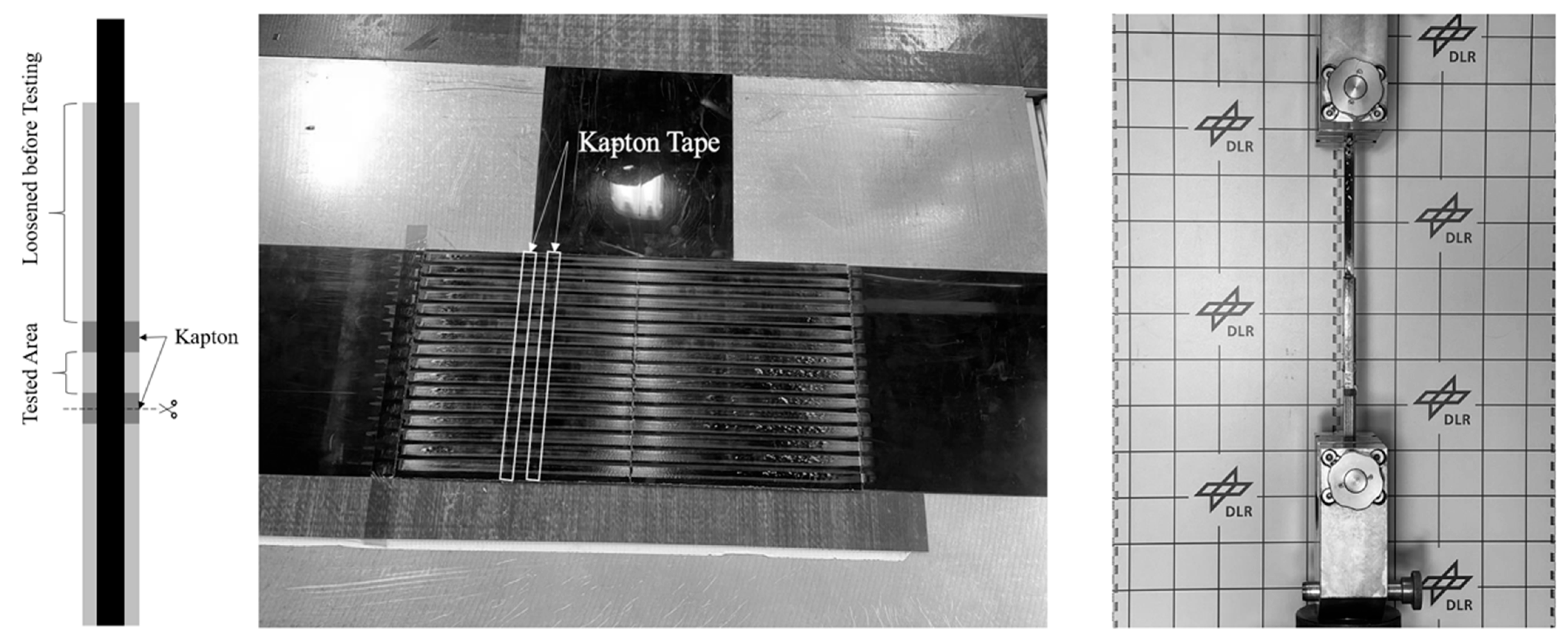
The specimens were produced using a casted sheet of PA6 as a substrate and 6.35 mm wide tapes. The casted sheets of PA6 were cut to a dimension of 200 mm × 200 mm. On each plate, 16 tapes were deposited using the in situ AFP process. CF/LM-PAEK tapes were laid on both sides of the PA6 sheets to produce the DLS specimens. Two stripes of polyimide (PI) tape were applied to the substrate with a gap of 12.5 mm in between. The PI tape prevents a bonding of the CF/LM-PAEK tapes to the substrate and defines the tested bonding area of a specimen. After the layup of the CF/LM-PAEK tapes, they are cut along one of the PI tapes. The preparation and the testing setup of the DLS specimens are shown in
Figure 3. The parameters for the production of the specimens are listed in
Table 2. The runs 1 to 5 were tested. A universal testing machine, RetroLine 1475 produced by the company ZwickRoell GmbH & Co. KG (Ulm, Germany), was used with a testing speed of 1 mm · min
−1.
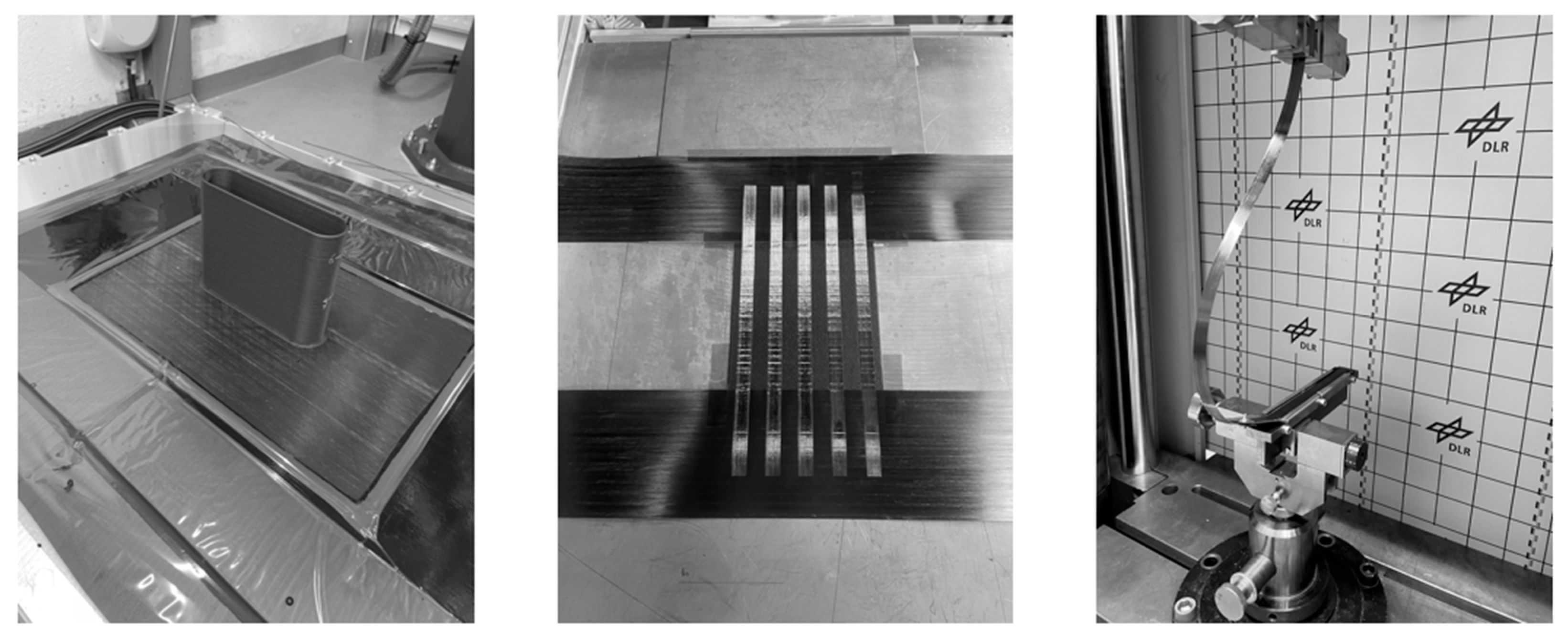
Using the findings of the DLS tests and under consideration of the standard DIN EN 28510-1, a sample size of 5 was determined to be sufficient for each run of the peel tests. These tests were chosen to further investigate the demolding characteristics of a laminate. The test procedure was based on DIN EN 28501-1. The specimens consisted of a 12.7 mm wide tape on a 3D-printed substrate. The substrates were 3D printed as a single-walled part out of which two plates could be separated as observed in
Figure 4. The wall thickness was set to 3 mm. After separation, the plates were mounted between two metal sheets of the same thickness, which had a layer of Toray Cetex TC 1225 prepreg fixed to their surface. The prepreg is used to prevent slipping of the tape. To minimize its influence on the bending behavior of the tape, the fibers of the prepreg were oriented orthogonal to those of the tapes. On one 3D-printed plate, five tapes were laid and later separated for testing. The test setup can be observed in
Figure 4. The parameters for the peel specimens are listed in
Table 2. The runs 1 to 4 were tested with a testing speed of 50 mm · min
−1.
The surface of the tape, which was bonded to the PA6 substrate, was analyzed using a Keyence VR-5000 profilometer to determine the surface roughness after testing of the specimens.
2.5. Statistics
For the comparison of two groups, an unpaired t-test was used. p-values of ≤0.05 were considered statistically significant. To account for alpha error, a Bonferroni–Holm correction was used.
4. Discussion
The process parameters of AFP need adjustment to be suitable for the bonding of LM-PAEK tapes onto PA6 substrates. The reduction in the process temperature is the most notable due to the lower melting temperature of PA6 compared to that of LM-PAEK. Since the substrate is heated above its melting temperature, the tape is laid onto a molten pool of PA6. Thus, the tape force needs to be reduced to prevent slipping of the tape and allow for accurate placement of the individual tapes. An increase in the consolidation pressure, which presses the tape onto the substrate, further benefits this mechanism.
Further, the increased consolidation pressure seems to promote a wet-out of the bonding surfaces, which is indicated by the morphological analysis and is concordant with the findings of Smiley et al. [
9]. The amorphous phase in the interface region can be explained by the rapid cooling of the PA6. Pesetsktii et al. [
14] found that a rapid cooling of PA6 can lead to an amorphous state, which will crystalize under room temperature over time. Frigione et al. [
15] found that, in thermoplastic in situ AFP of PAEK and PEI, a rapid cooling of the tapes occurs, which leads to an amorphous phase. This is most likely the cause for the amorphous phase of PA6 in the interlayer of the two polymers that was observed in this study.
The cracks in the PA6 substrate parallel to the bonding surface may be caused by thermal stress, applied pressure or a combination of both. If a crack proceeds into the interlayer, the amorphous phase can flow into it during its liquid state and create a form closure. An example of this is observable in
Figure 7d.
All variations in the parameters shown in
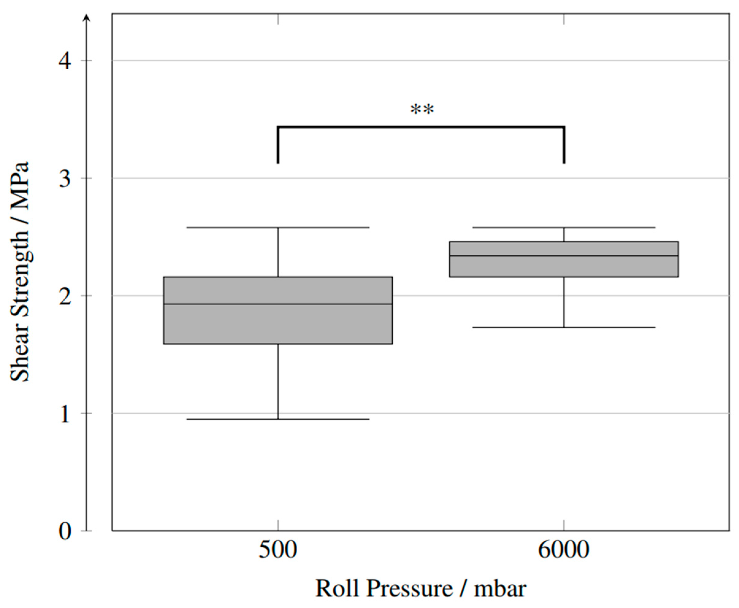
Table 2 can be characterized as LT bonding since the measured temperatures of the tape never exceeded the melting point of its matrix material. All variations except run 4 resulted in a substrate temperature below the melting point of PA6. It is, however, probable that the heated tape elevates the temperature of the substrate above its melting point upon contact. The relatively low substrate temperature that was measured at a process temperature of 420 °C and a laser position of 8 mm might be the reason for the statistically insignificant difference in peel strength and shear strength to other variations in the parameters as observed in
Figure 8 and
Figure 11.
In the production of laminates using AFP, a tape exhibits multiple heating cycles due to the passing of the laser over a position of the tape in proceeding layers. In this study, only the characteristics of the first ply were investigated. The additional heating cycles in a realistic manufacturing process of a laminate are likely to strengthen the bond by allowing for crystallization of the amorphous interlayer phase, healing in the interface and chain entanglement. If high stresses are present in the laminate early in the manufacturing process, it is also possible that the additional heating cycles may result in a failure of the bond since the interlayer could be heated above its melting point.
For the production of laminates using AFP, a heated tooling is beneficial to the interlaminar shear strength [
10]. This can be achieved in metallic molds. However, due to the relatively low glass-transition temperature of PA6, this is only possible to a limited extent with the proposed technology. In comparison with a metallic mold, the thermal conductivity of PA6 is significantly lower. This may contribute to a slower cooling of the tapes and thus a higher crystallinity in the laminate [
15]. Furthermore, a polymeric mold is most likely less stiff compared to a metallic tooling. This can reduce the laminate’s quality due to a reduction in consolidation pressure [
2].
Using a simulation to predict the warpage of the laminate, like that demonstrated by Fricke et al. [
16], the necessary strength of the bonding between tooling and the laminate can be estimated and used to choose suitable process parameters, according to the findings of this study.
For complex laminates, the process parameters may need to be adjusted along a single track. This is especially necessary if the tape is laid on a track that is concave and convex curved. This leads to a change in the forces acting orthogonal and in-plane with the tape along the track. These parameters were shown to influence the bonding strength.
Since no post-consolidation is required in in situ AFP, there is no need for vacuum bagging of the laminate, and thus, the mold does not need to be air-tight. This enables the use of additive manufacturing, e.g., fused granular fabrication, for the manufacturing of a tooling. Complex composite parts can be manufactured by the combination of those two additive manufacturing technologies, which was already demonstrated in a prior study [
17].
5. Conclusions
This study presents an experimental investigation of the suitability of polyamide 6 as a mold material for the automated fiber placement of carbon fiber-reinforced, low-melting polyaryletherketone. By using two incompatible polymers, a bond can be achieved that is strong enough to hold a laminate in the desired form during layup and allows for demolding. Further, a thermoplastic mold material can be processed using fused granular fabrication, and molds can be manufactured in an additive manner.
The principle suitability of polyamide 6 as a mold material for thermoplastic automated fiber placement was demonstrated. The results of the peel tests and shear tests presented in this work indicate an adjustability of the bonding strength by altering the process parameters of the automated fiber placement. It was found that lower process temperatures result in a weakened bond. A higher consolidation pressure is beneficial to the bonding strength.
The presented technology can be used to manufacture thermoplastic composites more economically and in a shorter time frame compared to ordinary mold concepts. Future work will focus on the effects of first-ply parameters for this technology on the laminate quality of manufactured parts.


