Article

Mode II Fatigue Delamination Growth and Healing of Bis-Maleimide Modified CFRPs by Using the Melt Electro-Writing Process Technique

by
Athanasios Kotrotsos
1 and
Vassilis Kostopoulos
1,2,*
1
Department of Mechanical Engineering and Aeronautics, University of Patras, GR-26504 Patras, Greece
2
Foundation of Research and Technology, Institute of Chemical Engineering Sciences (FORTH/ICE-HT), Stadiou Str., GR-26504 Patras, Greece
*
Author to whom correspondence should be addressed.
J. Compos. Sci. 2023, 7(9), 350; https://doi.org/10.3390/jcs7090350
Submission received: 11 July 2023 / Revised: 12 August 2023 / Accepted: 21 August 2023 / Published: 23 August 2023
(This article belongs to the Topic Advanced Carbon Fiber Reinforced Composite Materials)

Abstract

:
In the current study, the interlaminar fracture toughness behavior of high-performance carbon fiber-reinforced plastics (CFRPs) modified with Bis-maleimide (BMI) resin was investigated under Mode II quasi-static and fatigue remote loading conditions. Specifically, CFRPs were locally integrated with BMI resin, either nano-modified with graphene nano-platelets (GNPs) or unmodified, using the melt electro-writing process (MEP) technique. Following the modification, two types of CFRPs were manufactured: (a) CFRPs with pure BMI resin and (b) CFRPs with GNP-modified resin. Quasi-static tests demonstrated that the interlaminar fracture toughness properties of both modified CFRPs were significantly improved compared to the unmodified/reference CFRPs. Conversely, fatigue tests were conducted under displacement control, with crack length measurement performed using a traveling microscope. Delamination length and load quantities were measured at specific cycle intervals. The results indicated that both modified CFRPs exhibited enhanced resistance to delamination under Mode II fatigue loading, with earlier crack arrest, compared against the reference CFRPs. Additionally, the CFRPs displayed low healing efficiency (H.E.) after the healing cycle was activated. Overall, this approach shows promise in improving the delamination resistance of CFRPs under Mode II.

Graphical Abstract

1. Introduction

Fiber-reinforced plastics (FRPs) are widely used in various engineering fields due to their high strength, modulus, and corrosion resistance. However, these composites are prone to delamination and matrix cracking, which can lead to mechanical property degradation and potential failure [1]. Traditional repair methods, such as patch bonding and injection repair, have limitations, prompting the development of self-healing (SH) composite materials. SH composites aim to reduce weight, minimize waste, and extend the service life of structures by autonomously healing cracks within the polymeric matrix without external intervention [2]. The advantage of SH composites over conventional repair methods is that microscopic cracks can be automatically repaired before being detected by engineers, ensuring effective maintenance of structural integrity, and prolonging the service life.
The key objective of SH composites is to introduce SH agents into damaged areas [3]. There are two main categories of SH composites based on the incorporated healing mechanism within the matrix. The first mechanism involves containers, such as microcapsules or hollow fibers, that store liquid SH agents (extrinsic type). These containers are pre-embedded during the manufacturing process. When cracks propagate along the embedded microcapsules [4,5] or hollow fibers [6,7], the containers rupture, allowing the SH agent to flow out and heal the cracks through capillary action. Polymerization occurs between the resin and the available catalyst contained in separate containers within the composite matrix. The second mechanism utilizes reversible polymers that melt upon heating and directly fill the cracks (intrinsic type) [8,9]. These SH agents contain dynamic covalent bonds capable of restoring the material’s initial performance by activating their reversible capability. Unlike the extrinsic type, this type of SH agent is integrated as part of the entire molecular network of the polymeric composite material.
Intrinsically healed matrices appear to be the most promising approach for SH purposes, as they eliminate the need for hollow containers, which can act as stress concentration points and degrade mechanical properties [5]. Moreover, the intrinsic type of the SH mechanism offers unlimited healing capability as the SH agent remains intact within the composite structure [10]. Existing literature suggests that reversible polymers are often incorporated into the interlaminar region of composite structures [8,9,10]. These healable composites could repair matrix damage through thermo-reversible secondary interactions, such as covalent bonding (common thermoplastics) [11,12], hydrogen bonding [9], and the Diels–Alder (DA) reaction mechanism [3,8,9,10]. The SH capability of Bis-maleimide (BMI) resins is based on the DA reaction mechanism, which allows them to behave as a resin at ambient conditions and as a thermoplastic at elevated temperatures [13,14,15]. Recent studies utilizing DA-based polymers as SH agents have demonstrated impressive improvements in the interlaminar fracture toughness of composites, as well as acceptable healing efficiencies [3,8,9,10].
The solution electrospinning process is advantageous for SH applications as it enables the fabrication of core-shell structures containing the SH agent in liquid form [16]. Additionally, polymers containing dynamic covalent [17,18] or non-covalent interactions [19,20] can be easily electrospun. These fibrous structures could also be incorporated into a composite structure since they offer SH functionality on the polymer level. The melt electro-writing process (MEP) technique is utilized for fabricating fibrous structures from polymer melts [21]. In the present work, MEP was employed to locally modify high-performance carbon fiber-reinforced plastics (CFRPs) by directly printing ultrathin unidirectional (UD) fibers of BMI resin onto the surface of pre-pregs. In a previous study [10], the same methodology was used to investigate the effect of BMI modification by MEP on the Mode I quasi-static mechanical properties of CFRPs. Interestingly, the composite demonstrated significant enhancement in Mode I interlaminar fracture properties and acquired SH functionality.
The focus of the current work is on the estimation of fatigue lifetime and healing capability of UD CFRPs with BMI resin under Mode II loading conditions. Specifically, the CFRPs were locally modified using the MEP technique at targeted areas within their mid-thickness to eliminate potential knock-down effects. After the manufacturing process, reference CFRPs, modified CFRPs containing pure BMI resin, and modified CFRPs containing BMI resin modified by graphene nano-platelets (GNPs) at a 1 wt% loading were obtained. The CFRPs were subjected to Mode II quasi-static and Mode II fatigue tests, and the fractured samples underwent the healing process. The Mode II quasi-static tests revealed that the interlaminar fracture toughness properties were significantly enhanced in the GNPs-modified CFRPs, exhibiting the best toughening profile. Subsequently, Mode II fatigue tests were conducted under displacement control conditions at 0.9 of the critical displacement value (δcr) of the reference CFRPs, determined from Mode II quasi-static tests, for a pre-determined number of 50 k cycles. Based on experimental results, both modified CFRPs exhibited improved resistance to delamination, and the healed CFRPs were able to withstand 6 k cycles.

2. Materials and Methods

2.1. Materials

The commercial carbon fiber-epoxy pre-preg that was utilized is UD and was supplied by the SGL Group company in Germany. For the self-healable BMI resin synthesis, the BMI-1700 oligomers (Designer Molecules, San Diego, CA, USA) and the homemade trifurane (TF) compound were utilized. The synthesis of the TF is described in detail in Reference [3]. The four-layered (4L) GNPs that were utilized for nano-modification of the BMI resin were supplied by Cheap Tubes Inc., Cambridgeport, MA, USA. More information on the materials can be found in References [3,8].

2.2. Preparation of the BMI Resin

The BMI resin in cross-linked form, having SH functionality, was prepared by mixing BMI-1700 oligomers and the TF compound in a stoichiometric analogy. After mixing the reactants, the mixture was transferred into an oven in order for the cross-linking reaction to take place. More information on the preparation of the BMI resin, as well as on the nano-modification process, can be found in References [3,8] and is not included here.

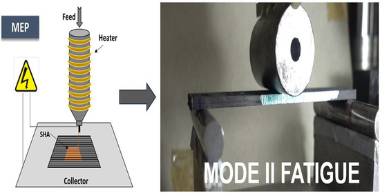
2.3. Pre-preg Modification by Melt Electro-Writing Process Technique

The incorporation of the BMI resin was performed by modification of the pre-preg plies directly by the MEP technique. More precisely, the pre-preg modification was performed locally and only at the targeted area to eliminate potential degradation of the final CFRP structure as well as for the material economy. The experimental parameters of the MEP procedure are the following: needle tip to collector distance of 3 mm, applied voltage of 4 kV while the feed rate was calculated to be 1.22 g/h. After MEP, the fibrous structure had an aerial weight of 48.8 g/m2, while the printed fibers had an average diameter of 150 ± 10 μm. More information on the pre-preg modification process can be found in [10].

2.4. Composites Manufacturing and Quality Control

The manufacturing process of the CFRPs comprises autoclave technologies. Each CFRP plate contains 22 pre-preg plies, while the modified CFPRs were locally modified into their mid-thickness area. More precisely, three types of CFRP laminates were manufactured; the reference CFRP, the BMI modified, and the BMI and GNP-modified CFRP, respectively. During the MEP process, the deposited BMI resin created a “fibrous interlayer” having the aim to toughen the CFRP and provide SH functionality. Figure 1 provides the mid-thickness area design of the CFRP plates, the C-scan inspection images after the quality control of them as well as an optical microscopy image of a modified pre-preg ply after the MEP technique. The design of the plates was performed to initially obtain samples intended to Mode I interlaminar fracture toughness tests. During the Mode I tests, the crack length was fixed to almost reach the SH area (Figure 1a, modified plate). The main concept behind this was to create a natural pre-crack area prior to cutting them to end-notched flexure (ENF) samples and afterward to execute the Mode II interlaminar fracture tests. The C-scan inspection images confirm the acceptable quality of the manufactured plates, as Figure 1 suggests. The images were taken by using a physical acoustics corporation system, having a 5 MHz transducer. The polymerization process of the obtained CFRP plates was achieved at 100 °C applied temperature, 4 bars applied pressure, for 5 h. Five samples of each CFRP plate were tested for every experiment type, while the final fiber volume fraction (Vf) was calculated to be 60 ± 2%.

2.5. Mode II Quasi-Static and Mode II Fatigue Testing

The Mode II quasi-static tests were conducted following the Airbus standard AITM 1.0006 [22]. A 25 kN Instron Universal testing machine was used for the testing at ambient conditions. In our case, a load cell having a capacity of 1 kN has been utilized, connected in series with the load cell of the machine, for more accuracy on the obtained load experimental values. Initially, Mode I tests were conducted according to the Airbus standard AITM 1.0005 [23]. To withstand the peel forces from the load cell, two aluminum tabs were adhered to the outer surfaces of the double cantilever beam (DCB) specimens using a two-component epoxy adhesive. Both the reference and modified CFRPs underwent the Mode I test to create a natural sharp pre-crack. Subsequently, the fractured samples were sectioned into Mode II (ENF) specimens following the AITM 1.0006 [22] standard. The natural pre-cracked ENF test specimens were subjected to three-point bending at a crosshead speed of 1 mm/min. Figure 2 illustrates a modified CFRP sample. The GIIC value was determined using Equation (1):
G I I C = 9 P α 2 d 2 w 1 4 L 3 + 3 α 3 k J m 2
where, d is the cross-head displacement at crack delamination onset, P is the critical load to start the crack, α is the initial crack length (from the support point to the end of the crack), w is the width of the specimen and L is the span length (L = 100 mm).
Until now, there is no standard available for the delamination in composites under Mode II cycling loading conditions. For the Mode II fatigue tests, all ENF samples were tested under displacement control at a frequency of 5 Hz and a compression-compression displacement ratio R = 0.1. The delamination growth rate data was generated by applying δImax corresponding to 0.9δcritical of the reference CFRP. The tests also were conducted for a pre-determined number of 50 k cycles. During the tests, a traveling microscope was utilized to measure the crack length at the end of precise loading cycles while load and delamination lengths were recorded at the same time. Based on fitted curves to the propagation data obtained from experimental results, the Paris’ law coefficients (m and c) were calculated as well as the dα/dN equations representing the region II of the delamination growth were determined. All the tests were conducted at the premises of the Applied Mechanics Laboratory (AML), University of Patras, Patras, Greece.

2.6. Healing Process

After the execution of the Mode II fatigue tests for the pre-determined number of 50 k cycles, the fractured CFRPs passed through the healing cycle to enable the healing functionality. The healing cycle consists of a thorough thickness and uniform heating at 130 °C for 30 min by applying uniform pressure of 0.16 bar. Based on previous investigations by the authors, the precise healing profile was proved to be the optimal one for this type of healing agent. After the heating process, the samples were left to cool down overnight by keeping the applied pressure. Then, samples were retested under the same experimental conditions. The healing efficiency (H.E.) calculation is based on Equation (2):
H . E . = N h e a l e d N d a m a g e d · 100   ( % )
where Ndamaged and Nhealed are the values of the property (in our case, the number of cycles) prior to and after the healing process, respectively.

3. Results and Discussion

3.1. Test Outline Program

The synthesis of the cross-linked BMI resin involved the mixing of BMI-1700 and TF compound in stoichiometric proportions. For the GNP-modified BMI resin, 1 wt% of the nanomaterial was uniformly dispersed into the resin before the cross-linking process. Additional details on the procedure can be found in References [3,8].
After the synthesis of the pure and nano-modified BMI resin, the following steps were followed:
(a) Incorporation of the BMI resin (either in pure or nano-modified form) using the MEP technique;
(b) Manufacturing of the three types of CFRP plates (i.e., reference, BMI-modified, and BMI & GNP modified) by utilizing autoclave technologies;
(c) C-scan inspection of the manufactured plates to assess their quality;
(d) Execution of Mode II quasi-static tests to determine the δcr value;
(e) Execution of Mode II fatigue tests using displacement control at 0.9 times the δcr value of the reference CFRP;
(f) Activation of the SH process and repetition of the Mode II fatigue tests under identical experimental conditions.
Figure 3 provides a detailed schematic of the planned experimental campaign.

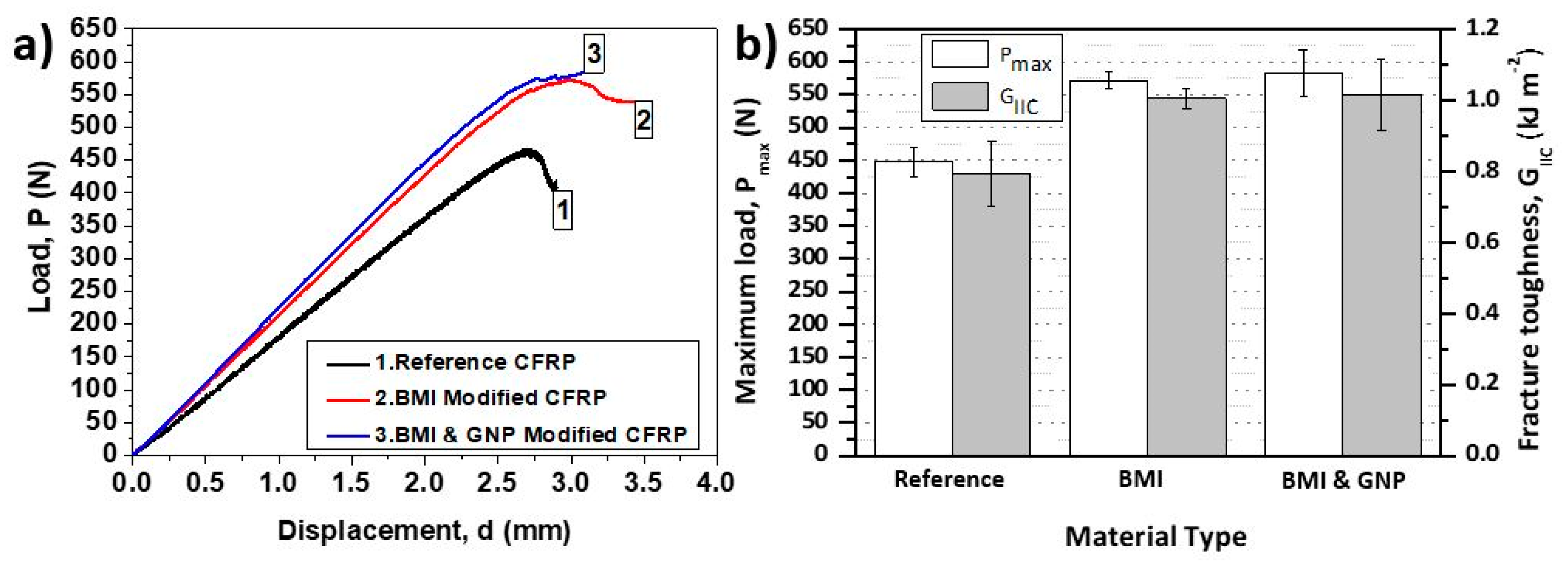
3.2. Mode II Quasi-Static Tests

The modification of the CFRPs by BMI resin (nano-modified or not) is expected to have an impact on the Mode II interlaminar fracture toughness properties of the final composite structure. In addition, there is a necessity to identify these properties in order for the delamination growth of these CFRPs under Mode II fatigue loading conditions to be investigated. The experimental specifications are based on the AITM 1.0006 [22] standard of the Airbus industry, and more details can be found in Section 2.5.
Figure 4 provides the representative load-displacement (P-d) curves (Figure 4a) and the bar chart diagram containing the average peak load (Pmax) and the average Mode II interlaminar fracture toughness (GIIC) values for the reference and both modified CFRPs (Figure 4b), respectively. More precisely, BMI-modified CFRPs exhibited a higher Pmax value by 27.9% (from 447.5 ± 21.4 to 572.4 ± 13.8 N) and a higher GIIC value by 23.6% (from 0.8 ± 0.28 to 0.98 ± 0.04 kJ/m2), while the BMI and GNP modified CFRPs exhibited higher Pmax value by 30.2% (from 447.5 ± 21.4 to 582.8 ± 66.1 N) and higher GIIC value by 31.19% (from 0.8 ± 0.28 to 1.04 ± 0.16 kJ/m2. An analogous behavior was also observed in [24], in which thermoplastic-type interleaves were incorporated into the mid-thickness area of composite structures. In addition, the δcr values for the reference CFRP material were determined, taking into consideration the P-d plots of the tested samples. Based on that, the δcr value was calculated to be 2.71 mm for the reference CFRP. Finally, optical microscopy images of the under-investigation samples can be found in Reference [10], in which the SHA (BMI resin) is clearly illustrated in the mid-thickness area of the CFRP structure.
After determining the Mode II interlaminar fracture toughness properties, the compliance calibration method (CCM) was employed to establish resistance curves (R-curves). This method is widely used as measuring crack length during a Mode II experiment is challenging due to microcracks that often deviate from the crack plane [25]. For each ENF sample, precise crack lengths of 35, 40, 45, 50, 55, and 60 mm were targeted, and the compliance values were calculated accordingly. The samples were manually positioned on anchor points to achieve the desired crack length for each test. During the Mode II loading, the Instron machine automatically recorded load-displacement data. Using this data, the compliance (C) values and the critical energy release rate (GII) were calculated. The compliance was determined by the slope of the loading line, while the GII value was calculated using the Irwin-Kies Equation (3) [26]:
G I I = P 2 2 b d C d α
where b is the width of the CFRP sample, P is the load, α is the crack length, and C is the compliance.
Figure 5 provides the compliance with respect to the crack length for all CFRP types, together with the equations of the fitted curves. During a Mode II quasi-static test, the relationship between the compliance is cubic and is assumed by Equation (4) [27]:
C = D + m α 3
where C is the compliance, D and m are constants, and α is the crack length. Based on that, the GII value is obtained by the following Equation (5):
G I I = 3 P 2 m α 2 2 b
After GII value calculation for all material sets and based on the predetermined crack lengths, the results were plotted with respect to the crack lengths, as Figure 6 suggests. The equations of the best-fitted curves are also provided together with the plot curves for the three material sets, respectively. As can be seen, both modified CFRPs’ curves are similar while entirely different against the reference CFRP material. Based on that, CFRPs modification seems to have significantly affected the crack evolution mechanism, as anticipated. For all cases, the GII value significantly increases as the crack length propagates. Also, it is clear the capacity of the BMI resin (nano-modified or not) to toughen the final CFRP structure, according to these plots. According to relative literature, both R-curve types are acceptable and in line with other works [28,29].

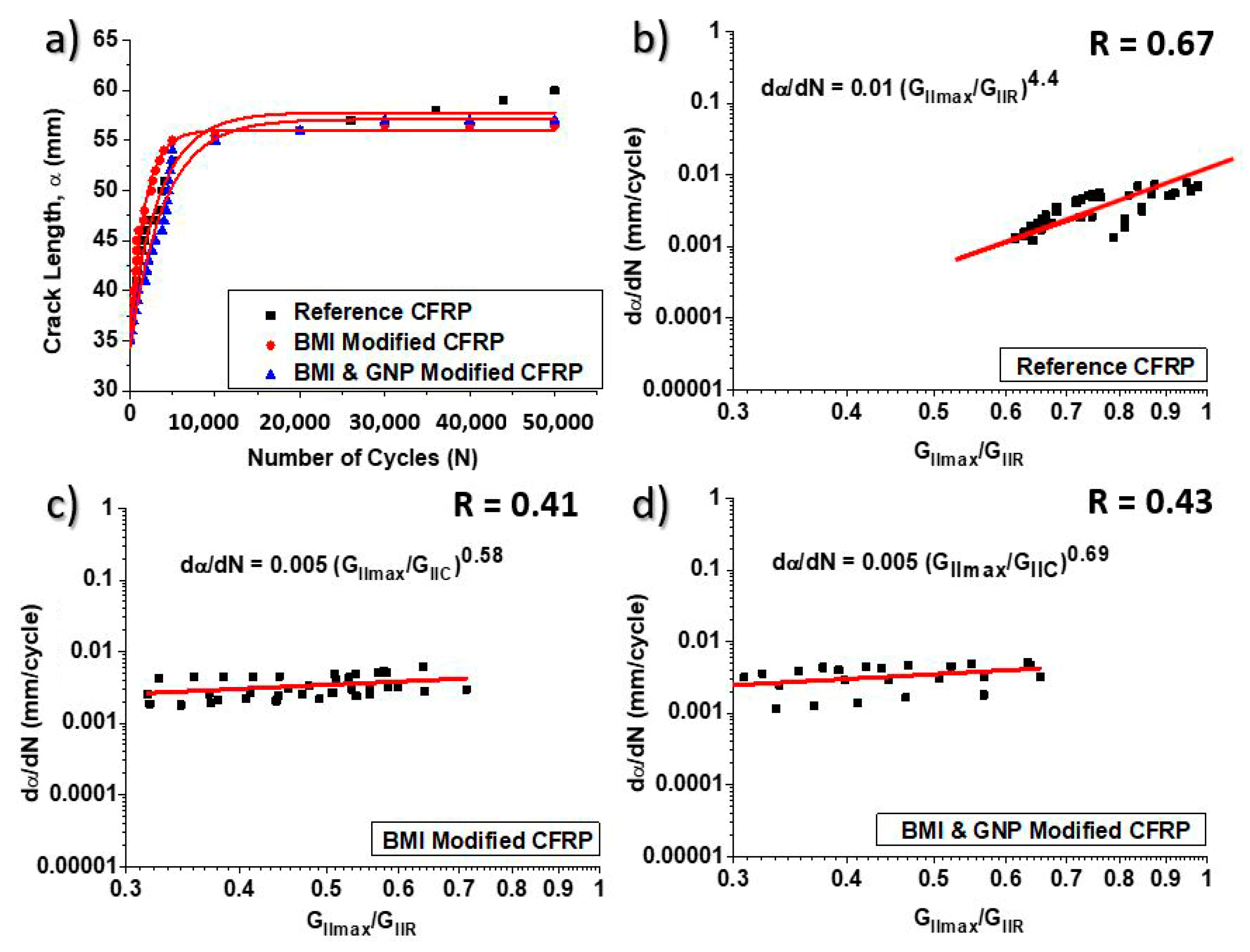
3.3. Delamination of CFRPs under Mode II Fatigue Loading Conditions

The Mode II fatigue experiments were conducted following the specifications outlined in Section 2.4, as there is no standard available for this type of testing. The objective of these experiments was to analyze the Mode II fatigue behavior of the samples using Pari’s law with respect to the Mode II energy release rate.
During the tests, the evolution of crack length was recorded using a traveling microscope over a predetermined number of 50 k cycles. Typically, measuring crack length during Mode II fatigue tests is challenging and not highly precise. To address this, at certain stages of the fatigue process, the crack length measurements at the front face of the test samples were confirmed by measurements taken at the rear face of the ENF samples. Generally, these two values were in good agreement. Figure 7a illustrates the crack propagation evolution (α) as a function of the number of cycles (N) for the three material sets (reference CFRP, BMI modified CFRP, and BMI and GNP modified CFRP). The experimental data indicates that both modified CFRPs exhibited better resistance to delamination compared to the reference CFRP. Specifically, the reference CFRP showed crack propagation of 25 mm (from 35 mm to 60 mm), the BMI-modified CFRP had 21.5 mm (from 35 mm to 56.5 mm), and the BMI and GNP-modified CFRP had 22 mm (from 35 mm to 57 mm). Based on the results, it can be concluded that the incorporation of BMI resin with or without GNPs had a positive effect on the Mode II fatigue performance of the CFRP structures. Similar behavior was observed in the Mode II quasi-static experiments conducted previously and described in Section 3.2.
During the Mode II fatigue tests, the quantities N, α, Δα, and PImax were recorded at the end of a specific number of cycles (ΔN). The δImax quantity was held constant throughout the tests for up to 50 k cycles. The maximum energy release rate (GIImax) was determined using the direct beam theory (DBT) method outlined in AITM 1.0006 standard [22], while the GIIR value was calculated based on the equations provided in Figure 7 for each CFRP type. Finally, the data of logdα/dN were plotted against logGIImax/GIIR for all material sets. In Figure 7, the best-fit linear curves were applied to the experimental propagation data, and the coefficients of the Paris’ law were calculated for each CFRP set. The coefficients for the reference CFRP were determined as m = 4.4 and C = 0.01, for the BMI-modified CFRP as m = 0.58 and C = 0.005, and for the BMI and GNP-modified CFRP as m = 0.69 and C = 0.005. These fitted curves align with other published studies [28,29] according to existing literature.

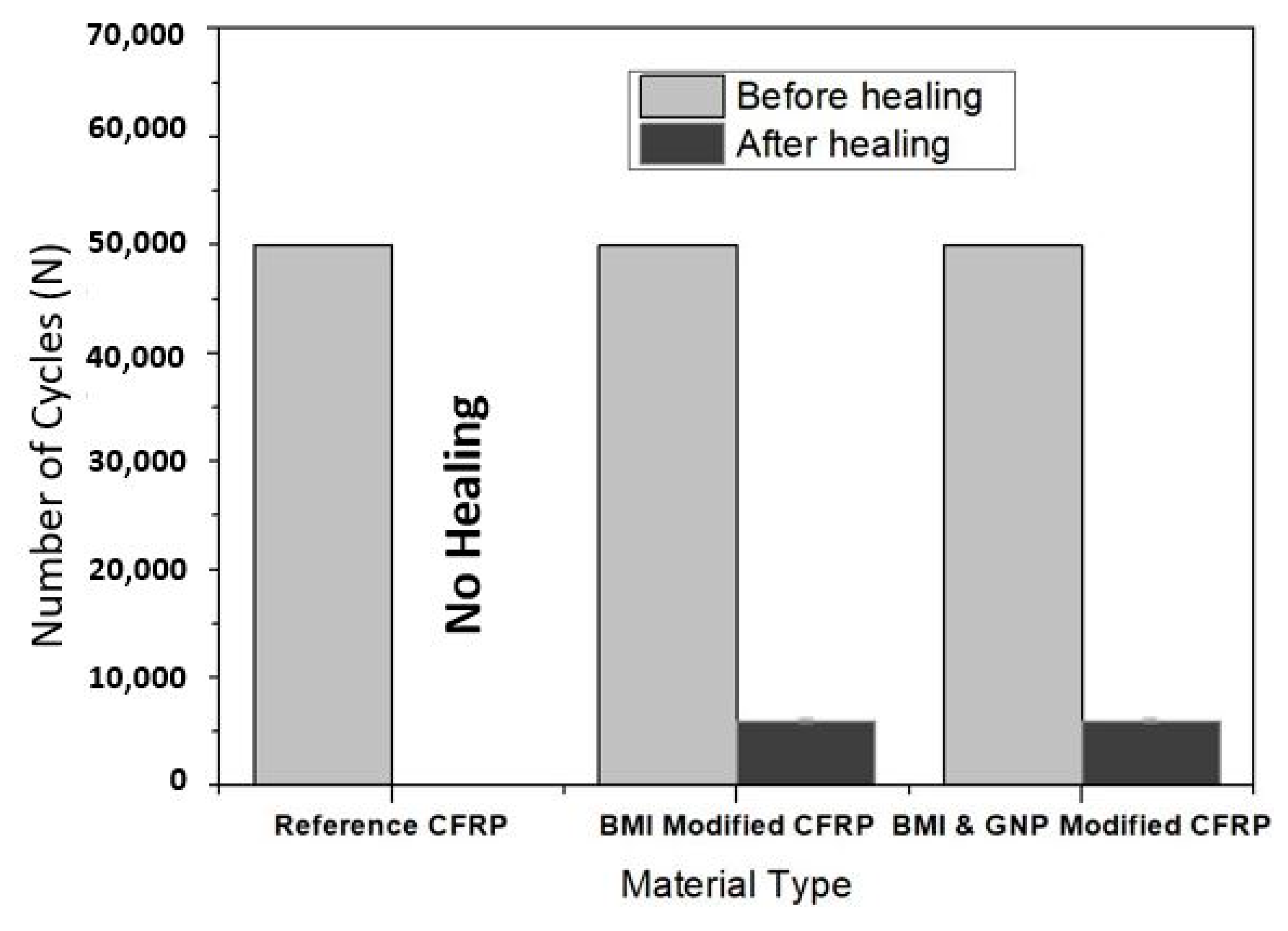
3.4. Repair of the Fractured CFRPS via the Healing Procedure

Following the completion of the Mode II fatigue experiments up to 50 k cycles, both modified CFRPs underwent the healing process. The healed samples were retested under identical conditions to assess their fatigue behavior. The healing process involved uniformly heating and compressing the modified samples, as specified in Section 2.6. The reference samples, which do not possess healing capability, were not subjected to the precise healing cycle [8].
According to Figure 8, both modified CFRPs were able to withstand approximately 6 k cycles until they reached the initial delamination length observed in the initial fatigue tests of the pristine samples. Thus, the presence of GNPs in the BMI resin did not appear to have affected the Mode II fatigue behavior of the samples after the healing process was activated. During the healing process, the BMI resin melted and filled the delaminated area, resulting in the restoration of a portion of the mechanical performance of the samples. Based on the obtained results, an H.E. of 12% was achieved for both modified CFRPs.

4. Conclusions

In the current work, fatigue life estimation for delamination growth of modified CFRPs with BMI resin (containing or nor GNPs) under Mode II fatigue loading conditions was assessed. Initially, Mode II quasi-static experiments were conducted in order for the Mode II interlaminar fracture toughness properties and the δcr value of the reference CFRP to be determined. Based on the experimental results, it was shown that both modified CFRPs exhibited enhanced Mode II interlaminar fracture toughness properties, with the GNP-modified ones presenting the best resistance to delamination. Afterward, constant amplitude, displacement-controlled Mode II fatigue tests were also executed for all CFRPs to evaluate the delamination growth rate (dα/dN) with respect to the maximum cyclic energy release rate (GIImax), taking into consideration the Paris’ law. The tests showed that both modified CFRPs presented better resistance to delamination while the Paris’ law material constants c and m were obtained. Finally, after the activation of the healing process, both modified CFRPs were able to withstand approximately 6 k cycles until they reached the initial delamination length, presenting an H.E. value of 12%.

Author Contributions

Conceptualization, methodology, investigation, validation, A.K. and V.K.; formal analysis, data curation, writing—original draft preparation, funding acquisition, A.K.; writing—review and editing, project administration, A.K. and V.K.; supervision, V.K. All authors have read and agreed to the published version of the manuscript.

Funding

This research is co-financed by Greece and the European Union (European Social Fund- ESF) through the Operational Programme «Human Resources Development, Education and Lifelong Learning» in the context of the project “Reinforcement of Postdoctoral Researchers–2nd Cycle” (MIS-5033021), implemented by the State Scholarships Foundation (IKϒ).

Data Availability Statement

Data sharing not applicable.

Conflicts of Interest

The authors declare no conflict of interest.

References

  1. O’Brien, T.K. Towards a damage tolerance philosophy for composite materials and structures. Compos. Mater. Test. Des. ASTM Spec. Tech. Publ. 1990, 1059, 7–33. [Google Scholar]
  2. White, S.R.; Sottos, N.R.; Geubelle, P.H.; Moore, J.S.; Kessler, M.R.; Sriram, S.R.; Brown, E.N.; Viswanathan, S. Autonomic healing of polymer composites. Nature 2001, 409, 794–797. [Google Scholar] [CrossRef]
  3. Kostopoulos, V.; Kotrotsos, A.; Geitona, A.; Tsantzalis, S. Low velocity impact response and post impact assessment of carbon fibre/epoxy composites modified with Diels-Alder based healing agent. A novel approach. Compos. Part A Appl. Sci. Manuf. 2021, 140, 106151. [Google Scholar] [CrossRef]
  4. Kosarli, M.; Foteinidis, G.; Tsirka, K.; Bekas, D.G.; Paipetis, A.S. Concurrent recovery of mechanical and electrical properties in nanomodified capsule-based self-healing epoxies. Polymer 2021, 227, 123843. [Google Scholar]
  5. Kosarli, M.; Bekas, D.G.; Tsirka, K.; Baltzis, D.; Vaimakis-Tsogkas, D.T.; Orfanidis, S.; Papavassiliou, G.; Paipetis, A.S. Microcapsule-based self-healing materials: Healing efficiency and toughness reduction vs. capsule size. Compos. Part B Eng. 2019, 171, 78–86. [Google Scholar] [CrossRef]
  6. Pang, J.W.C.; Bond, I.P. A hollow fibre reinforced polymer composite encompassing self-healing and enhanced damage visibility. Compos. Sci. Technol. 2005, 65, 1791–1799. [Google Scholar] [CrossRef]
  7. Hamilton, A.R.; Sottos, N.R.; White, S.R. Pressurized vascular systems for self-healing materials. J. R. Soc. Interface 2012, 9, 1020–1028. [Google Scholar]
  8. Kotrotsos, A.; Rouvalis, C.; Geitona, A.; Kostopoulos, V. Toughening and healing of CFRPs by electrospun diels-alder based polymers modified with carbon nano-fillers. J. Compos. Sci. 2021, 5, 242. [Google Scholar] [CrossRef]
  9. Kostopoulos, V.; Kotrotsos, A. Self-healing of Structural Composites Containing Dendrimers as Healing Agent. In Dendrimers-Fundamentals and Applications; Simonescu, C.M., Ed.; Intech Open Science: London, UK, 2018; Chapter 6; pp. 101–132. [Google Scholar]
  10. Kotrotsos, A.; Michailidis, G.; Geitona, A.; Tourlomousis, F.; Kostopoulos, V. Toughening and healing of CFRPs by Diels-alder based nano-modified resin through melt electro-writing process technique. Int. J. Mol. Sci. 2022, 23, 3663. [Google Scholar] [CrossRef]
  11. Meure, S.; Wu, D.Y.; Furman, S. Polyethylene-co-methacrylic acid healing agents formendable epoxy resins. Acta Mater. 2009, 57, 4312–4320. [Google Scholar] [CrossRef]
  12. Pingkarawat, K.; Wang, C.H.; Varley, R.J.; Mouritz, A.P. Self-healing of delamination cracks in mendable epoxy matrix laminates using poly[ethylene-co-(methacrylic acid)]thermoplastic. Comp. Part A Appl. Sci. Manuf. 2012, 43, 1301–1307. [Google Scholar] [CrossRef]
  13. Kennedy, J.P.; Castner, K.F. Thermally reversible polymer systems by cyclopentadienylation. I. A model for termination by cyclopentadienylation of olefin polymerization. J. Polym. Sci. Pol. Chem. 1979, 17, 2039–2054. [Google Scholar] [CrossRef]
  14. Chen, X.; Dam, M.A.; Ono, K.; Mal, A.; Shen, H.; Nutt, S.R.; Sheran, K.; Wudl, F. A thermally remendable cross-linked polymeric material. Science 2002, 295, 1698–1702. [Google Scholar] [CrossRef] [PubMed]
  15. Park, J.S.; Darlington, T.; Starr, A.F.; Takahashi, K.; Riendeau, J.; Hahn, H.T. Multiple healing effects of thermally activated self-healing composites based on Diels–Alder reaction. Compos. Sci. Technol. 2010, 70, 2154–2159. [Google Scholar] [CrossRef]
  16. Kotrotsos, A. An innovative synergy between solution electrospinning process technique and self-healing of materials. A critical review. Polym. Eng. Sci. 2020, 61, 5–21. [Google Scholar] [CrossRef]
  17. Moon, S.C.; Choi, J.K.; Farris, R.J. Preparation of Aligned Polyetherimide Fiber by Electrospinning. J. Appl. Polym. Sci. 2008, 109, 691–694. [Google Scholar] [CrossRef]
  18. Sung-Seen, C.; Seung Goo, L.; Chang Whan, J.; Seung Soon, I.; Seong Hun, K. Formation of interfiber bondingin electrospun poly(etherimide) nanofiber web. J. Mater. Sci. 2004, 39, 1511–1513. [Google Scholar]
  19. Yan, X.Z.; Zhou, M.; Chen, J.Z.; Chi, X.D.; Dong, S.Y.; Zhang, M.M.; Ding, X.; Yu, Y.H.; Shao, S.; Huang, F.H. Supramolecular polymer nanofibers via electrospinning of a heteroditopic monomer. Chem. Commun. 2011, 47, 7086–7088. [Google Scholar] [CrossRef]
  20. Hermida-Merino, D.; Belal, M.; Greenland, B.W.; Woodward, P.; Slark, A.T.; Davis, F.J.; Mitchell, G.R.; Hamley, I.W.; Hayes, W. Electrospun supramolecular polymer fibres. Eur. Polym. J. 2012, 48, 1249–1255. [Google Scholar] [CrossRef]
  21. Tourlomousis, F.; Ding, H.; Kalyon, D.M.; Chang, R.C. Melt Electrospinning Writing Process Guided by a “Printability Number”. J. Manuf. Sci. Eng. 2017, 139, 081004. [Google Scholar] [CrossRef]
  22. AITM 1.0006; Airbus Industry Test Method, Carbon Fiber Reinforced Plastics. Determination of Interlaminar Fracture Toughness Energy. Mode II. Cedex: Blagnac, France, 1994.
  23. AITM 1.0005; Airbus Industry Test Method, Carbon Fiber Reinforced Plastics. Determination of Interlaminar Fracture Toughness Energy, Mode I. Cedex: Blagnac, France, 1994; Issue 2.
  24. Wang, C.H.; Sidhu, K.; Yang, T.; Zhang, J.; Shanks, R. Interlayer self-healing and toughening of carbon fibre/epoxy composites using copolymer films. Comp. Part A 2012, 43, 512–518. [Google Scholar] [CrossRef]
  25. de Moura, M.F.S.F. Interlaminar Mode II Fracture Characterization, Delamination Behaviour of Composites. In Book Delamination Behaviour of Composites; Sridharan, S., Ed.; Woodhead Publishing: Sawston, UK, 2008; pp. 310–326. [Google Scholar]
  26. Davies, P.; Blackman, B.R.K.; Brunner, A.J. Mode II delamination. In Fracture Mechanics Testing Methods for Polymers Adhesives and Composites; Moore, D.R., Pavan, A., Williams, J.G., Eds.; E-Publishing Inc.: Amsterdam, The Netherlands; New York, NY, USA; London, UK, 2001; pp. 307–334. [Google Scholar]
  27. Kanninen, M.F.; Popelar, C.H. Advanced Fracture Mechanics, 1st ed.; Oxford University Press: Oxford, UK, 1985. [Google Scholar]
  28. Arrese, A.; Carbajal, N.; Vargas, G.; Mujika, F. A new method for determining mode II R-curve by the End-Notched Flexure test. Eng. Fract. Mech. 2010, 77, 51–70. [Google Scholar] [CrossRef]
  29. Kotrotsos, A.; Geitona, A.; Kostopoulos, V. On the mode I and mode II fatigue delamination growth of CFRPs modified by electrospun Bis-maleimide resin. Compos. Sci. Technol. 2023, 237, 110000. [Google Scholar] [CrossRef]
Figure 1. (a) Schematic representation of a reference and a modified CFRP plate. (b) Illustration of a BMI-modified pre-preg surface by the Melt electro-writing process (MEP). (c) Representative C-scan inspection images for all CFRP plates. (d) Illustration of the fibrous mesh morphology employed for the needs of the current study.
Jcs 07 00350 g001
Figure 2. (a) Illustration of a BMI-modified end-notched flexure (ENF) sample; (a) side view, (b) top view (dimensions in mm).
Jcs 07 00350 g002
Figure 3. Illustration of the scheduled experimental campaign, which was conducted for the needs of the current work.
Jcs 07 00350 g003
Figure 4. (a) Typical load (P) versus displacement (d) curves for reference and both modified CFRPs, (b) bar chart diagram containing the peak load (Pmax) and the interlaminar fracture toughness energy II (GIIC) experimental values.
Jcs 07 00350 g004
Figure 5. Compliance (C) vs. crack length (α) for (1) the reference CFRP, (2) the BMI-modified CFRP, and (3) the BMI and GNP-modified CFRP, respectively, during the Mode II quasi-static tests.
Jcs 07 00350 g005
Figure 6. Energy release rate (GII) versus delamination growth (α) according to Mode II quasi-static tests conducted for (a) the reference and the modified CFRPs with (b) BMI and with (c) BMI and GNPs, by using the compliance calibration method (CCM).
Jcs 07 00350 g006
Figure 7. (a) Crack length (α) with respect to the number of cycles (N) for all CFRP material sets during the Mode II fatigue tests. Crack propagation curves for (b) the reference, (c) the BMI modified, and (d) the BMI and GNP modified CFRPs, respectively. Pearson’s correlation coefficient (R) is also provided for all material sets.
Jcs 07 00350 g007
Figure 8. Bar chart diagram, providing the number of cycles (N) during the Mode II fatigue experiments for all CFRPs, prior to and after the application of the healing cycle.
Jcs 07 00350 g008
Disclaimer/Publisher’s Note: The statements, opinions and data contained in all publications are solely those of the individual author(s) and contributor(s) and not of MDPI and/or the editor(s). MDPI and/or the editor(s) disclaim responsibility for any injury to people or property resulting from any ideas, methods, instructions or products referred to in the content.

