Article

Asymmetric/Symmetric Glass-Fibre-Filled Polyamide 66 Gears—A Systematic Fatigue Life Study

by
Sandeep C. Dhaduti
1,
S. G. Sarganachari
2,
Arun Y. Patil
3,*,
Shridhar H. Budapanahalli
1 and
Raman Kumar
4
1
Mechanical Engineering Department, K.L.E. Institute of Technology, Hubballi 580027, Karnataka, India
2
Mechanical Engineering Department, Basaveshwar Engineering College, Vidayagiri, Bagalkot 587102, Karnataka, India
3
Department of Mechanical Engineering, Manipal Institute of Technology Bengaluru, Manipal Academy of Higher Education, Manipal 576104, Karnataka, India
4
University Centre for Research and Development, Department of Mechanical Engineering, Chandigarh University, Gharuan, Mohali 140413, Punjab, India
*
Author to whom correspondence should be addressed.
J. Compos. Sci. 2023, 7(9), 345; https://doi.org/10.3390/jcs7090345
Submission received: 10 July 2023 / Revised: 1 August 2023 / Accepted: 9 August 2023 / Published: 22 August 2023
(This article belongs to the Section Fiber Composites)

Abstract

:
This work aims to determine how the behaviour of symmetry and asymmetry can affect the bending fatigue performance of glass-fibre-filled PA66 gears. Gears with pressure angles ranging from 20° to 35° at increment steps of 5° on the driving side and 20° on the coast side are considered. Temperature in the gear contact region was recorded at various torque levels to examine the effects of increasing torque on different polymer test gears and gear profiles. According to the findings of the fatigue test, the PA66/40GF gear demonstrated a 23% increase in fatigue life when the pressure angle on the drive side was increased from 20° to 35° and a 38% increase when a torque of 0.8 Nm was applied. When put under bending stress levels ranging from 13.11 MPa to 32.76 MPa, the performance of the PA66/40GF gear with a 20–35° gear profile was exceptional. However, for a torque of 2 Nm, this test gear was unable to withstand and cross 106 stress cycles. Along with the inclusion of glass fibre, the increased driving-side pressure angle improved the fatigue performance of polymer test gears. This leads to the conclusion that PA66/40GF is a better material for gears.

1. Introduction

Gears play a crucial role in transmitting power in mechanical systems under a range of loads and speeds. Different metals and non-metals are utilised for producing gears [1]. Due to their functionality and economic benefits, polymer gears have mainly substituted metal gears in numerous applications. The developments happening in the research field and the evolution in our understanding of plastic gears has led to widespread utilization of these gears in various appliances. The Freedonia Organisation found that demand for polymer gears surged by 83% between 2003 and 2013. Compared to 2003, when this rise was USD 710 million, it was USD 1300 million in 2013 [2]. The metal–polymer gear combination under oil lubrication is able to transmit power up to 30 kW, which currently satisfies the basic requirements for using them in small-scale city vehicles. The Victrex Polymer gear manufacturer designed a gear for automobile engine transmission capable of handling torque up to 40 Nm at an operating speed of 6000 rpm under an operating temperature of more than 150 °C. There are a few issues relating to load carrying and lightweight levels, opening up new potential for polymeric gears in the power transmission in industries, including aviation, new energy vehicles, and e-bikes [3].
Polymer gear materials have become more prevalent during the last few decades. In the second part of the 20th century, when plastic gears first appeared on the market, they were mostly employed as a less expensive alternative to metal gears in simple uses. The injection moulding technique is widely used to manufacture cost-effective plastic gears. Polyamides (PA46, PA66, PA12, and PA6), polyoxymethylene (POM), polybutylene terephthalate (PBT), and high-density polyethylene (HDPE) are the most used materials for gears [4]. PA and PAGF gears are corrosion-resistant and noiseless in operation; however, they are not appropriate for heavy load transmission [5]. There are various applications where polymer gears have replaced conventional metal gears. In domestic appliances, small motors, and printers, PA and PAGF gears are utilised [6]. Due to high mechanical properties, rigidity, durability against wear, fatigue strength, dimensional consistency, and water resistance, PA and PAGF are frequently utilised for gear production [7]. The elastic moduli of plastics, which are about one hundred times less than those of steels, are the fundamental difference between the behaviours of metal and polymer gears. Owing to the reduced heat conductivity of polymer materials, gear pairs made from these materials will experience less heat dissipation and increased heat accumulation [8]. The portion of accumulated heat is transferred to the meshing gear and some parts of the gear testing machine, while the remaining heat is dissipated into the surroundings by convection [9]. Without lubrication, polymer gears experience superficial wear, localised melting, and pitting, whereas with lubrication, they experience bending fatigue failure at the root area of the gear teeth [5,10,11]. Reinforcement can decrease the damping capabilities of polymer composites. Fibre-reinforced polymers reduce the quantity of internal heat produced under repeated stress conditions [12]. The reinforcing elements also improve the transmission efficiency in polymer–steel gear pairs rather than polymer–polymer gear pairs. Transmission efficiency is not governed by changing the operating speed [13]. The stress–life (S-N) behaviour, also known as the S-N curve, is a popular way to describe the fatigue damage of polymer materials characterized by cyclic mechanical stresses [14]. The shortage of material information in terms of temperature–time (or load) cycle curves T(t) (or T(N)) and fatigue life S(N) that determine the endurance of polymeric substances is the primary drawback of employing plastic gears. This information guarantees accurate calculations for actual power train applications [15]. Under heavy loads and lubricated operating conditions, the main type of failure seen in polymer gears is fatigue at the root region and contact region. The presence of lubrication in polymer gears decreases abrasion and the amount of heat generated at the gear mesh region. This is leading to new studies related to polymer gear failure mechanisms and modes under lubrication [3]. The polymer gears manufactured via injection moulding operate silently. Specially designed gears produce less noise when compared to involute gears [16].
Compared to normal gears, the stress created at the zone of gear engagement is lower for asymmetric gears. An increased gear ratio and tooth count also help to lower contact stress [17,18]. As the thickness of the tooth increases, less bending force is exerted on the tooth of the gear. The load-bearing capacity approaches its peak value at 45° pressure angles [19]. Gears with an asymmetric profile can reduce bending stress and increase performance and load-bearing capability [20]. The results from the test reveal that bending stress can be reduced by 40%, and the contact stress can be reduced by 13.5% [21]. It is possible to create tooth geometry for an asymmetric gear using parametric analysis [22,23]. Increases in the drive-side pressure angle lead to decreases in the stresses developed at the root region of the asymmetric gears, thus enhancing the fatigue performance [24]. An efficient way to improve the power transmission effectiveness is to increase the drive-side pressure angle of the gear teeth. Up to a drive-side pressure angle of 35°, the bending stress reduces; after that, it increases as the drive-side pressure angle increases. In order to prevent interference, a drive-side pressure angle of 35° is considered, while a pressure angle of 20° is taken into account for the coast side.
Asymmetric gear designs with a high pressure angle on the drive side are rare among conventional steel gear applications. Since these gears tend to be noisy, they possess a low contact ratio [17]. With an increase in the drive-side pressure angle, the gear tooth profile becomes pointed and fails to support the applied load [18]. Survey results clearly show that polymer-based spur gears are the focus of most research, with a symmetric gear profile and not an asymmetric gear profile [4].
According to a literature review, significant research has been conducted on changing the drive-side pressure angle, fillet radius, width of the gear tooth, inserting steel pins inside the gear tooth, drilling holes for better heat dissipation, reinforcing glass fibres, carbon fibres, nanotubes, and nano clay. Studies have also focused on the thermal, tribological and fatigue behaviour, transmission efficiency, noise generation, and damping characteristics of polymer gears. The fatigue performance of gears with a drive-side pressure angle of 34–35° has been investigated. Various numerical techniques such as FEM and Moldflow simulations software have been used to predict gear performance. In contrast, no experimental investigation has yet been conducted to determine the impact of glass fibre content combined with different combinations of pressure angles. Hence, this work primarily focuses on the thermal and fatigue behaviour of glass-fibre-filled PA66 gears with a glass fibre content increasing from 20 wt. % to 40 wt. %, with a drive-side pressure angle varying from 20° to 35° in steps of 5°, and using an in-house gear test rig under constant speed and unlubricated conditions.

2. Methodology

PA66 embedded with 20 wt. %, 30 wt. %, and 40 wt. % glass fibre composite material was utilized to manufacture gears using injection moulding. The polymer gear and standard stainless-steel gears (SS304L) are presented in Figure 1. Table 1 shows the gear specifications. The mechanical properties of glass fiber are depicted in Table 2.
A gear fatigue testing system was devised to assess the effectiveness of PA and PAGF gears. SS304L-grade steel gear was positioned on a shaft coupled to a permanent magnetic DC motor meshing with the PA and PAGF gears keyed on the shaft (1.5 kW and speed 1500 rpm). The motor and speed regulator are connected, allowing the speed to be adjusted to a required speed. The PA and PAGF gears are driven by a steel gear. Rope wrapped around the pulley and attached to the shaft supporting the PA and PAGF gears was used to apply a resistance torque. At the rope’s end, loads were suspended, generating the required torque to be applied on the gears. An IT-1520 temperature-sensing device measured the gear pair temperature at the mesh region. A speed sensor and counter tracked the gear rotational speed and cycle count. Figure 2 indicated the size of two gears. Figure 3 depicts the gear fatigue testing machine.
Gears were tested under constant 1000 rpm speed and torque levels of 0.8, 1.2, 1.6, and 2.0 Nm. Rotational speed has no noticeable effect on the gear fatigue life [19]; hence, it is constant in this investigation. The operational speed governs the temperature generated at the gear mesh zone, both in the glass-fibre-filled PA6 gears and the unfilled PA6 gears. The experiment was conducted for 106 cycles or until the PA and PAGF gears failed. At ambient temperatures and without lubrication, the gears were tested. At the gear mating interface zone, a thermal sensor monitored the temperature continuously. The number of revolutions was recorded using a digital counter [20,21,22].
The polymer gear performance was studied using a polymer–polymer gear pair and a polymer–steel gear pair. Less gear damage due to an increase in temperature at the gear pair region was observed in the polymer–metal gear rather than the polymer–polymer gear pair. The reason for this is that the heat generated was lost through convection [4]. As both conduction and convection mechanisms take place, the plastic–metal gear pairing dissipates heat at a higher rate. When the polymer gear meshes with the steel gear, the entire deformation is observed on the polymer gear, due to the low strength of the polymer material [17].

3. Results and Discussions

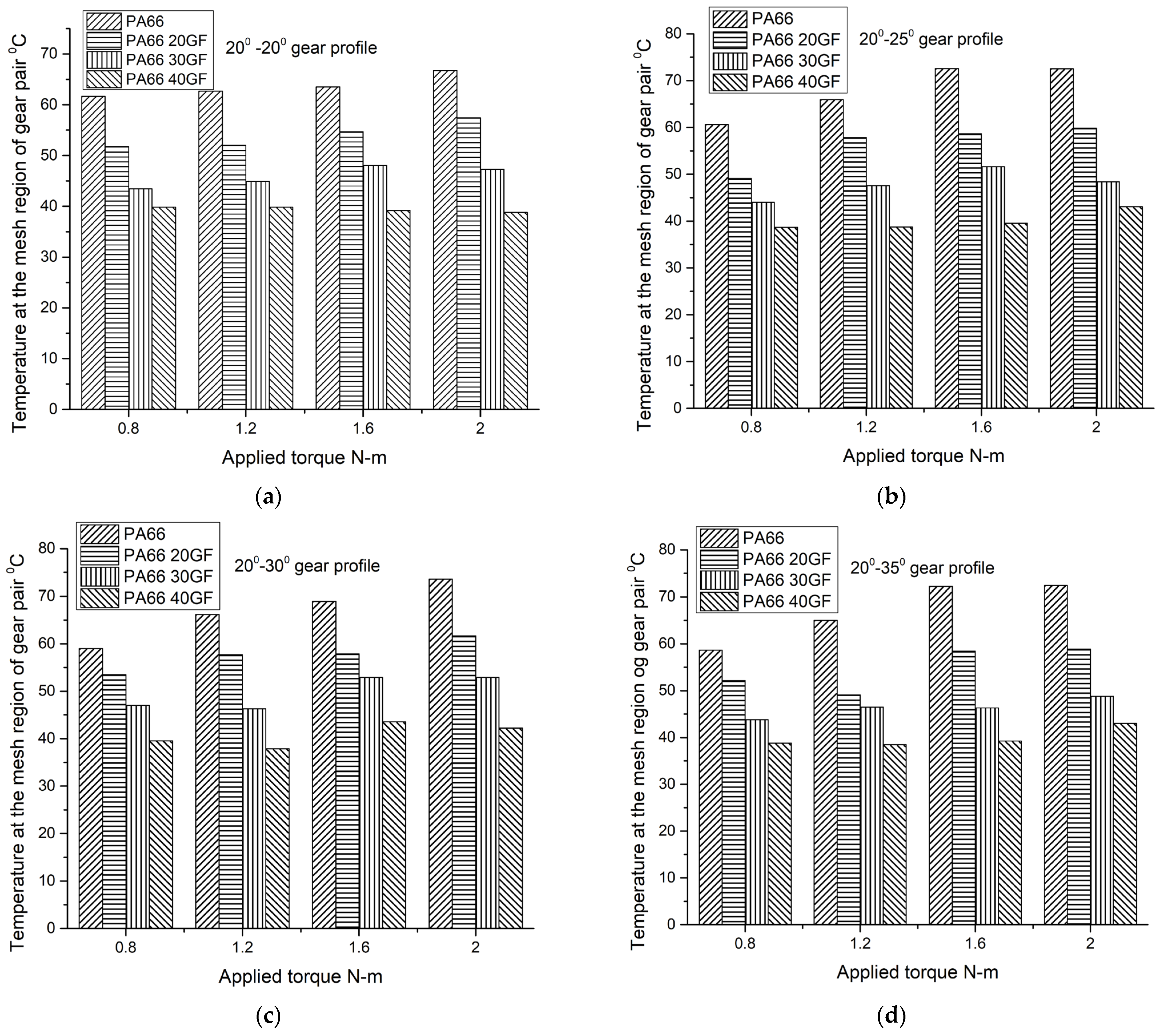
3.1. Thermal Behaviour of Gears

During polymer–polymer gear mating, the temperature at the interface increases with a rise in applied torque [25]. Because the operational temperature has a greater impact on polyamide gear mechanical qualities, it is necessary to consider this factor while performing investigation. Compared to metallic gears, polymeric gears have a more complex and difficult-to-understand fatigue mechanism due to the influence of the heat created while running [26]. According to certain studies, the gear pair meshing zone will experience increased wear and early fatigue failure under heavy loads if the temperature at that location rises with the load (torque) and speeds [27]. Frictional and hysteresis heating are the two main heat generating sources in polymer gears. The interaction between a pair of sliding surfaces results in frictional heating, whereas viscoelastic deformation results in hysteresis heating. The heat produced at the mesh region of polymeric gears causes teeth to become soft and distort whenever they are exposed to high torque [28]. The heat generated at the gear flank region was found to be influenced by the input load or torque more than speed of sliding by seven to eight times, and it found to be extremely sensitive to a large number of fatigue cycles [29]. The surface temperature of the gear consists of three components, namely the surrounding air temperature, increase in temperature of meshing zone of gear, and rise in temperature at the meshing region of the gear pair for short duration of time. These temperatures will lead the mesh gear pair to reach near to melting point temperature with increase in applied load and operating speeds [30]. The temperature raise is greater in the beginning but stabilizes after a certain interval of running. The gear temperature quickly increases as a result of the friction amongst meshing gears. When the temperature rises above the ambient temperature after a given amount of time, metal gears begin to transfer heat to the atmosphere. This causes the temperature rise at the mesh area to slow down and approach equilibrium. [5]. The temperature at the interaction zone of the gear pair is impacted by the addition of reinforcement. Due to the greater thermal conductivity of glass fibre, which also helps to dissipate more heat, the glass-fibre-containing polyamide gears showed a lower increase in surface temperature [31]. By changing the width region of PA6 gear, this results in a reduction in the temperature generated at the mesh zone of the gear pair. The gear tooth width-modified PA6 gear resulted in less wear and premature failure, thus enhancing the fatigue life as compared to the unmodified PA6 gear [32]. Drilling holes in the gear tooth region delayed the failure of the PA6 gear because these holes enhanced heat dissipation to the surroundings. This led to new design of gears with a prolonged service life as compared to normal gears [33]. The increase in surface temperature θs of gears can be predicted by using Equation (1).
θ s = 0.625 μ T c ρ Z b r a 2 r 2
where µ is the frictional co-efficient of the polymeric gear material, T is applied torque in Nm, c is specific heat of polymeric gear material, ρ is specific gravity of polymer material, Z is number of teeth, b is face width of gear, ra is outer circle radius of gear in m, and r is pitch circle radius in m [5]. The surface roughness of the metal gear has a greater influence on heat generation in the polymer gear. The steel gear with high surface roughness results in heat generation in the polymer gear [34].
Figure 4a–d and Table 3 provide the thermal responses for several profiles of PA66 and PA66GF gears at variable torque.
Torque induced during the experimentation has a greater influence on temperature at the mating region of the steel and PA and PAGF gears than speed. Temperature gradually decreased as the induced torque increased and the amount of glass fibre in the PA66 gear sample increased. The utilization of glass fibres increases the rigidity of the gears, which decreases tooth deflection and lowers heat production at the physical contact of mating gears [31].
Across all gear profiles, the temperature at the surface of an unreinforced PA66 gear continued to rise with torque. Since the quantity of heat produced during the meshing of steel and PA and PAGF gears is greater, it is controlled by the amount of induced torque and the driving-side pressure angle [35]. The heat accumulated at the gear-to-gear interface also grows as the drive-side pressure angle of the PA and PAGF gears and the torque induced rises [25].

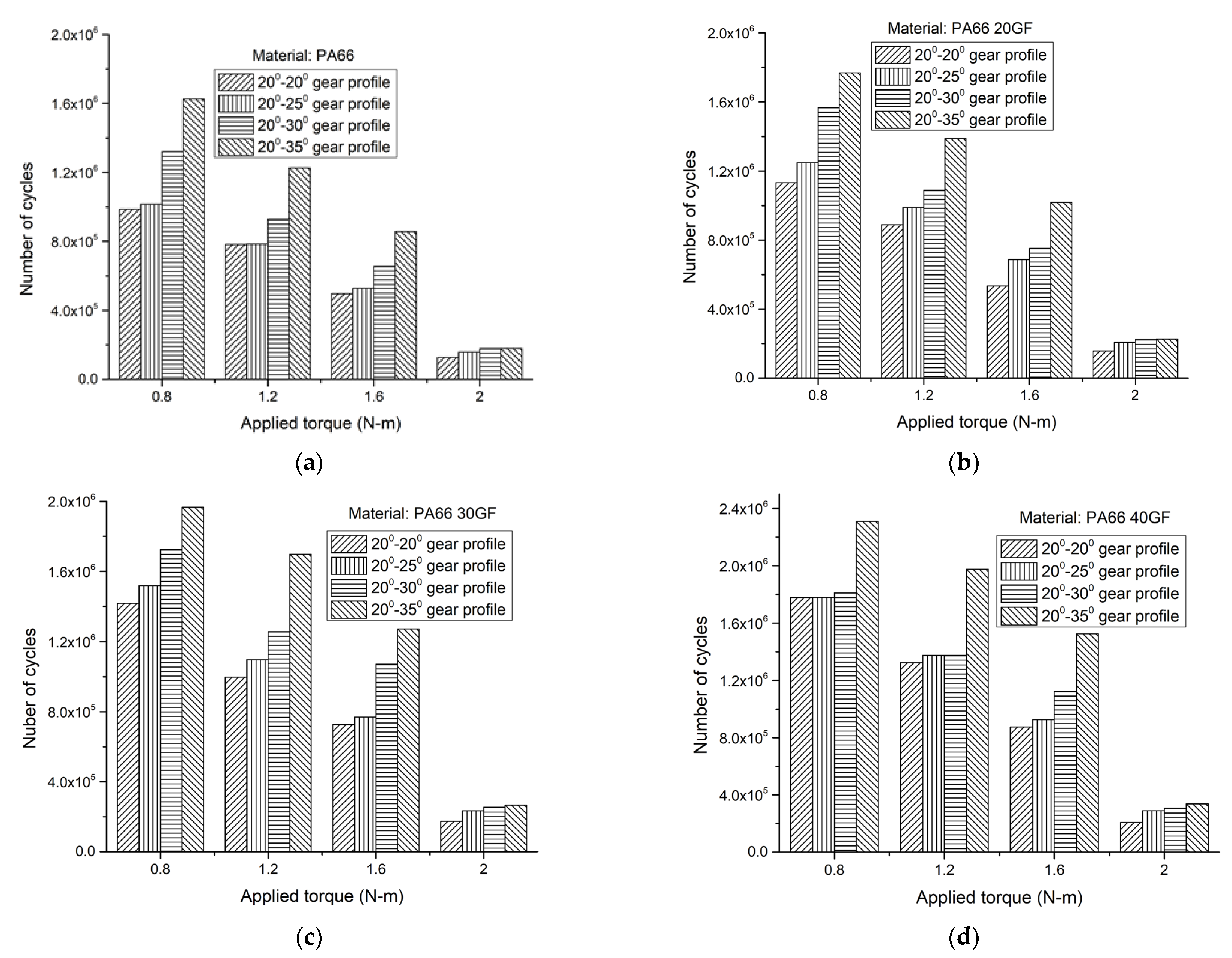
3.2. Gear Fatigue Performance

Polymer gears fail due to wear or fatigue loading. Gears experience fatigue failure as a result of bending stress in the fillet area and cyclic contact stress occurring on the surface of the gear tooth. Compared to contact fatigue, bending fatigue has been identified to be the main cause of failure. The development of micro-cracks at the tooth’s root region, tooth bending, and tooth fractures are all the result of fatigue failure of gears.
To gain an insight into how mating gear material affects the fatigue performance of the gear pair, the maximum root bending stress must be determined. Equation (2) is used to find bending stresses at the fillet region [22]. Figure 5 indicates parameters required to find bending stress. According to ISO 6336, the root region of the gear becomes the critical section where the failure occurs. The thickness of critical section Scr can be obtained by drawing a line at an angle of 30° from the tooth centre line tangent to the fillet radius. This critical section remains at the same point even if the location of the loading point changes [24].
σ b = F t ( b ) ( m ) Y S Y F
where, YF is the gear tooth shape factor,
Y F = 6 h F m cos α L d S c r m 2 cos α
Ys is the stress rectification factor,
Y S = 1.2 + 0.13 L q s a
The terms in Equation (3) are represented by Equations (4)–(6).
L = S c r h F
q s = S c r 2 ρ f   Fillet   radius   ρ f = 0.78   mm
a = 1.21 + 2.3 L 1
The load is delivered at HPSTC, and the gear tooth behaves as a cantilever lever beam. At the critical section, the applied load will be acting throughout the width of gear face. The load’s normal component Fn is split into its tangential component Ft, causing the gear to bend at the gear root region and radial component Fr, resulting in inducing compressive stress on gear tooth. As the drive-side pressure angle increases, the critical section thickness Scr and load angle on the drive-side αLd increase, and the height of the bending moment arm also increases. This results in a lower bending stress acting at the gear root region. In order to transmit power effectively, tip thickness is a crucial design factor for gears [15]. The tip becomes significantly pointed and is not suitable for transferring power if the tip thickness is less than 0.25 times that of the module. However, the tooth tip thickness reduced from 1.19 mm to 0.35 mm as the drive-side pressure angle changed from 20° to 35°. Another parameter which influences the drive-side pressure angle is the contact ratio. The contact ratio for gears decreases with an increase in drive-side pressure angle. In this study, the contact ratio decreased from 1.529 to 1.238 as the drive-side pressure angle changed from 20° to 35°. The effective length of the bending moment arm of the asymmetric gear of 20°–35° is more than that of the symmetric gear, 20°–20°, which led to enhancement in fatigue life. The bending stresses developed at the gear root region was 32.76 MPa for the 20°–20° gear and 29.78 for the 20°–35° gear for an applied torque of 2 Nm. In this context, it can be concluded that by increasing the drive-side pressure to 35° from 20°, while keeping the coast-side pressure angle 20° constant, lowered the bending stress.
Figure 6a–d illustrate the fatigue responses of PA and PAGF gears with various gear profiles. Figure 6a shows the fatigue life of 20°–20° polymer gears. When a bending stress of 13.11 MPa was applied, all PA and PAGF gears demonstrated exceptional performance through 106 cycles. When bending stress was raised to 26.21 MPa and 32.76 MPa, the polymer gear survival life dropped to fewer than 106 cycles. Only PA66/40GF outperformed the other gears when put under the same 19.66 MPa bending stress.
The 20°–25° PA and PAGF gears exceeded 106 cyclic counts in Figure 6b with a 12.90 MPa bending stress. Both PA66/30GF and PA66/40GF were able to withstand bending stresses of 19.35 MPa for more than 106 cyclic counts. The number of cycles of survival increased substantially less for torques of 2 Nm m (bending stress: 32.24 MPa). When the pressure angle was raised to 25° from 20°, fatigue life was substantially improved for a bending stress of 12.90 MPa and 106 cycles. Performance gradually improved with an enhancement in driving-side pressure angle from 20° to 35°.
All 20°–30° profile PA and PAGF gears lasted and exceeded 106 cycles under an induced bending stress of 13.24 MPa, as depicted in Figure 6c. All PAGF gears, with the exception of the PA66 gear, lasted and exceeded 106 cycles under a bending stress of 19.87 MPa, although only PA66/30GF and PA66/40GF with 20°–25° profile gears endured for an acceptable life. In comparison to the 20°–25° profile gears for the same load, PA66/30GF and PA66/40GF gears sustained and exceeded 106 cycles when bending stress was elevated to 26.49 MPa. PA and PAGF gears were unable to endure a bending stress of 31.62 MPa for 106 cycles.
PA and PAGF gears exceeded 106 cycles under an imposed bending stresses of 11.91 MPa and 17.87 MPa, as illustrated in Figure 6d, indicating a better performance of the 20°–35° gear. As compared to gears with 20°–30° gear profiles, the PA66/20GF, PA66/30GF, and PA66/40GF gears with a 20°–35° profile could withstand bending stresses of up to 23.82 MPa and crossing 106 cycles. Correspondingly, Figure 7 a–d compare the fatigue outcomes of PA and PAGF gears with various profiles for applied torque against number of cycles.
As illustrated in Figure 7a,b, 20°–35° profile PA66 and PA66/20GF gears demonstrated superior fatigue outcomes when exposed to torques of 0.8, 1.2, and 1.6 Nm m than did 20°–30° profile gears. When 2 Nm m torque was applied, the functionality of all gears was not satisfactory. However, when tested under 2 Nm torque, the operating characteristics of 20°–20°, 20°–25°, 20°–30°, and 20°–35° profile gears made from PA66 and PA66/20GF remained essentially the same, with no appreciable increase in cyclic counts of survivals. As seen in Figure 7c and Figure 7d, respectively, the efficacy of the 20°–30° and 20°–35° gears made from PA66/30GF and PA66/40GF demonstrated improved functionality under torques of 0.8, 1.2, and 1.6 Nm.
According to Figure 7d, a PA66/40GF gear with a 20°–35° profile endured more cycles than a 20°–30° profile gear under 0.8 Nm m torque. For a specified 1.2 Nm bending stress, the variation in the cycle life of survival among 20°–35° and 20°–30° profile gears manufactured of PA66/40GF stays unchanged. Temperatures at the gear mating zone are much higher for PA66 gears than for glass-fibre-reinforced PA66 gears. Increases in temperature as well as torque exerted at the gear contact zone caused premature breakdown of PA66 gears. The operating temperature affected the bending fatigue behaviour of polymer–polymer pairs, whereas the maximum bending stress affected the performance of steel–polymer pairings in the fillet.

4. Conclusions

In the present study, an attempt is made to study the behaviour of symmetric and asymmetric glass-fibre-reinforced PA66 gears. The pressure angle on the drive side was increased from 20° to 35° in steps of 5°, while the coast-side pressure angle of 200 was kept constant. The gears were driven at a constant speed of 1000 rpm with applied torque ranging from 0.8 to 2 Nm. Bending fatigue testing of PA66 and PA66GF with 20°–20°, 20°–25°, 20°–30°, and 20°–35° profile gears led to several conclusions.
The gear parameters such as contact ratio, radius at HPSTC, load angle on drive-side pressure angle, gear tooth thickness at critical section, and bending moment arm height can be utilised to calculate the bending stress at the gear root region. Gear life was shortened because of the pressure angle on the drive side of the gear increasing from 20° to 35°, which resulted in a decrease in tip thickness of 70.58% and pointed teeth that could no longer handle the load being applied. It was discovered that the bending stress acting at the gear root region is significantly influenced by these gear properties.
When torque raised from 0.8 to 2 Nm, the mating zone temperature for the PA66 gear increased by 16.10%. The PA66/20GF gear with a 20°–35° profile exhibited a temperature increase of 11.40%, compared to 10.29% for the PA66/30GF gear. However, with PA66 40GF, the temperature increased by 9.74%. The inclusion of glass fibre content reduced the amount of heat generated at the meshing region, while a quantity of heat is also dissipated to the steel gear.
The gear tooth bending stress for a 20°–35° gear profile with a torque of 2 Nm m was 29.78 MPa, which was the least of all the gear profiles. An increase in pressure angle of 35° on the drive side reduced the bending stresses by 10%.
The PA66/40GF gear displayed a rise of 23 percent in fatigue life when the driving-side pressure angle was raised to 35° for 0.8 Nm m torque. For 2 Nm m torque, a 38% improvement in fatigue life was reported. As the drive-side pressure angle increases, contact ratio decreases, and the height of the bending arm and gear tooth thickness at the critical section increases, which leads to a decrease in bending stress at the gear root region.
The PA66/40GF gear with a 20°–35° profile demonstrated superior performance. The performance of PA66GF gears against fatigue was improved via an increase in driving-side pressure angle. Thus, PA66/40GF is a better material for gears.

Author Contributions

Conceptualisation, S.C.D., S.G.S., A.Y.P., S.H.B. and R.K.; methodology, S.C.D. and A.Y.P.; software, S.C.D., S.G.S., A.Y.P. and S.H.B.; validation, S.C.D., S.G.S. A.Y.P. and S.H.B.; formal analysis, S.C.D., S.G.S., A.Y.P. and S.H.B.; investigation, S.C.D., A.Y.P., S.H.B. and R.K.; resources, S.C.D., S.H.B. and R.K.; data curation, S.C.D., S.G.S. and A.Y.P.; writing—S.C.D. and A.Y.P.; writing—review and editing, S.C.D., S.G.S., A.Y.P. and S.H.B.; visualization, S.C.D. and A.Y.P.; supervision, A.Y.P. and S.G.S.; project administration, R.K. and A.Y.P.; funding acquisition, A.Y.P. All authors have read and agreed to the published version of the manuscript.

Funding

This research received no external funding.

Institutional Review Board Statement

Not applicable.

Informed Consent Statement

Not applicable.

Conflicts of Interest

The authors declare no conflict of interest.

Abbreviations

PAPolyamides;
PAGFGlass-fibre-reinforced polyamides;
PA66/20GFPolyamide 66 with 20 wt. % glass fibre;
PA66/30GFPolyamide 66 with 30 wt. % glass fibre;
PA66/40GFPolyamide 66 with 40 wt. % glass fibre;
20°/20°Pressure angle coast side/pressure angle drive side;
σ b 
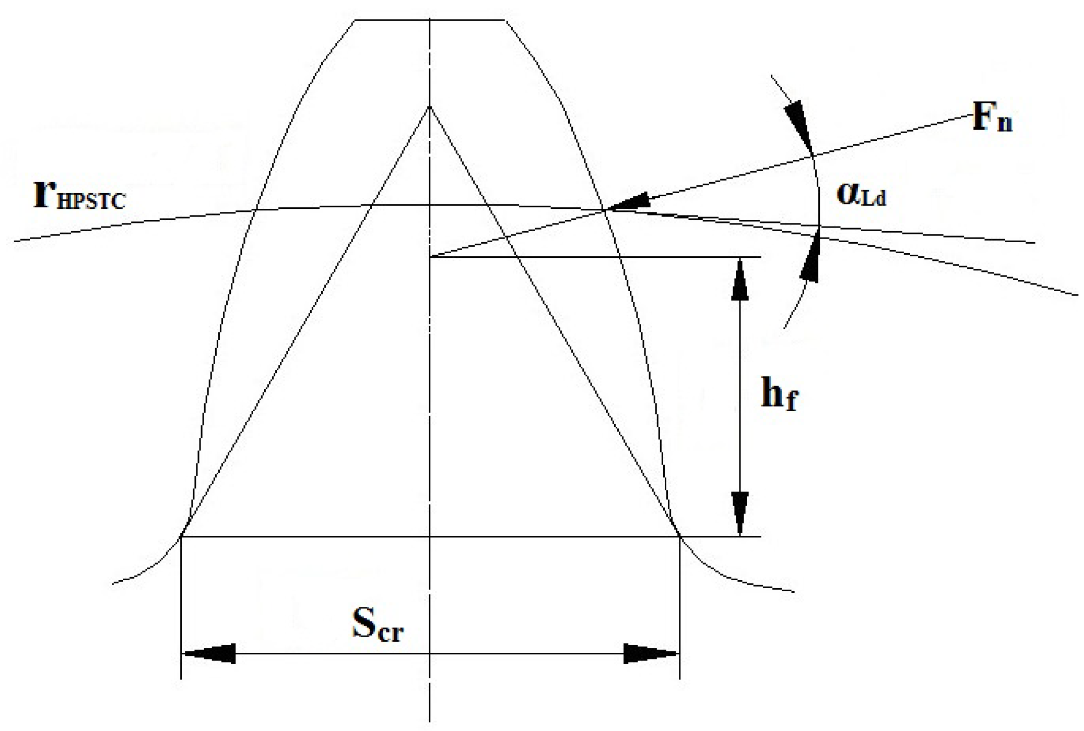
Bending stress at the fillet region of gear tooth in N/mm2;
mModule, b- face width in mm;
hFHeight of bending moment arm in mm;
αLdLoad angle on the drive side in deg.;
ScrGear tooth thickness at critical section in mm;
HPSTCHighest point of single-tooth contact;
r HPSTCRadius at highest point of single-tooth contact.

References

  1. Starzhinsky, V.E. Polymer Gears. In Encyclopedia of Tribology; Wang, Q.J., Chung, Y.-W., Eds.; Springer: Boston, MA, USA, 2013; pp. 2592–2602. ISBN 978-0-387-92897-5. [Google Scholar]
  2. Bravo, A.; Toubal, L.; Koffi, D.; Erchiqui, F. Gear fatigue life and thermomechanical behavior of novel green and bio-composite materials VS high-performance thermoplastics. Polym. Test. 2018, 66, 403–414. [Google Scholar] [CrossRef]
  3. Liu, G.; Wei, P.; Chen, K.; Liu, H.; Lu, Z. Polymer gear contact fatigue reliability evaluation with small data set based on machine learning. J. Comput. Des. Engineering 2022, 9, 583–597. [Google Scholar] [CrossRef]
  4. Hribersek, M.; Erjavec, M.; Hlebanja, G.; Kulovec, S. Durability testing and characterization of POM gears. Eng. Fail. Anal. 2021, 124, 105377. [Google Scholar] [CrossRef]
  5. Singh, P.K.; Siddhartha; Singh, A.K. An investigation on the thermal and wear behavior of polymer based spur gears. Tribol. Int. 2018, 118, 264–272. [Google Scholar] [CrossRef]
  6. Zorko, D. Investigation on the high-cycle tooth bending fatigue and thermo-mechanical behavior of polymer gears with a progressive curved path of contact. Int. J. Fatigue 2021, 151, 106394. [Google Scholar] [CrossRef]
  7. Singh, A.K.; Siddhartha; Singh, P.K. Polymer spur gears behaviors under different loading conditions: A review. Proc. Inst. Mech. Eng. Part J J. Eng. Tribol. 2018, 232, 210–228. [Google Scholar] [CrossRef]
  8. Zorko, D.; Tavčar, J.; Bizjak, M.; Šturm, R.; Bergant, Z. High cycle fatigue behaviour of autoclave-cured woven carbon fibre-reinforced polymer composite gears. Polym. Test. 2021, 102, 107339. [Google Scholar] [CrossRef]
  9. Černe, B.; Petkovšek, M.; Duhovnik, J.; Tavčar, J. Thermo-mechanical modeling of polymer spur gears with experimental validation using high-speed infrared thermography. Mech. Mach. Theory 2020, 146, 103734. [Google Scholar] [CrossRef]
  10. Md Ghazali, W.; Nafiz, D.; Sofian, A.; Siregar, J.; Aziz, I. A review on failure characteristics of polymer gear. MATEC Web Conf. 2017, 90, 01029. [Google Scholar] [CrossRef]
  11. Lu, Z.; Liu, H.; Zhu, C.; Song, H.; Yu, G. Identification of failure modes of a PEEK-steel gear pair under lubrication. Int. J. Fatigue 2019, 125, 342–348. [Google Scholar] [CrossRef]
  12. Senthilvelan, S.; Gnanamoorthy, R. Damping characteristics of unreinforced, glass and carbon fiber reinforced nylon 6/6 spur gears. Polym. Test. 2006, 25, 56–62. [Google Scholar] [CrossRef]
  13. Singh, A.K.; Singh, P.K.; Siddhartha; Yadav, S. A Comparative Analysis of Transmission Efficiency of Polyamide 66 Spur Gears Meshing with Similar and Dissimilar Gear Material. In Recent Advances in Mechanical Engineering; Lecture Notes in Mechanical Engineering; Muzammil, M., Chandra, A., Kankar, P.K., Kumar, H., Eds.; Springer: Singapore, 2021; pp. 291–297. [Google Scholar]
  14. Chandran, K.S.R. Mechanical fatigue of polymers: A new approach to characterize the SN behavior on the basis of macroscopic crack growth mechanism. Polymer 2016, 91, 222–238. [Google Scholar] [CrossRef]
  15. Hriberšek, M.; Kulovec, S. Thermal and durability characterization of polyacetal and polyamide gear pairs. J. Mech. Sci. Technol. 2021, 35, 3389–3394. [Google Scholar] [CrossRef]
  16. Trobentar, B.; Hriberšek, M.; Kulovec, S.; Glodež, S.; Belšak, A. Noise Evaluation of S-Polymer Gears. Polymers 2022, 14, 438. [Google Scholar] [CrossRef]
  17. Marimuthu, P.; Muthuveerappan, G. Investigation of load carrying capacity of asymmetric high contact ratio spur gear based on load sharing using direct gear design approach. Mech. Mach. Theory 2016, 96, 52–74. [Google Scholar] [CrossRef]
  18. Ml, P.; Goud, M. Static contact behavior of asymmetric spur gear. Mater. Today Proc. 2021, 47, 3095–3104. [Google Scholar] [CrossRef]
  19. Masuyama, T. Evaluation of load capacity of gears with an asymmetric tooth profile. Int. J. Mech. Mater. Eng. 2016, 9, 11. [Google Scholar] [CrossRef]
  20. Deng, G.; Nakanishi, T.; Inoue, K. Bending Load Capacity Enhancement Using an Asymmetric Tooth Profile. JSME Int. J. Ser. C 2003, 46, 1171–1177. [Google Scholar] [CrossRef]
  21. Namboothiri, N.V.; Marimuthu, P. Investigation of fracture behaviour of asymmetric spur gear. Theor. Appl. Fract. Mech. 2021, 114, 102991. [Google Scholar] [CrossRef]
  22. Vaghela, P.; Prajapati, J. Parametric analysis of asymmetric involute spur gear tooth. Int. J. Powertrains 2019, 8, 292. [Google Scholar] [CrossRef]
  23. Mallesh, G. Parametric analysis of Asymmetric Spur Gear Tooth. In Proceedings of the 14th National Conference on Machines and Mechanis, Durgapur, India, 17–18 December 2009; p. 6. [Google Scholar]
  24. Demet, S.M.; Ersoyoğlu, A.S. An analysis of the effect of pressure angle change on bending fatigue performance in asymmetrical spur gears. Proc. Inst. Mech. Eng. Part L J. Mater. Des. Appl. 2021, 235, 2142–2150. [Google Scholar] [CrossRef]
  25. Senthilvelan, S.; Gnanamoorthy, R. Effect of gear tooth fillet radius on the performance of injection molded Nylon 6/6 gears. Mater. Des. 2006, 27, 632–639. [Google Scholar] [CrossRef]
  26. Lu, Z.; Liu, H.; Zhang, R.; Zhu, C.; Shen, Y.; Xin, D. The simulation and experiment research on contact fatigue performance of acetal gears. Mech. Mater. 2021, 154, 103719. [Google Scholar] [CrossRef]
  27. Kalin, M.; Kupec, A. The dominant effect of temperature on the fatigue behaviour of polymer gears. Wear 2017, 376–377, 1339–1346. [Google Scholar] [CrossRef]
  28. Zorko, D.; Kulovec, S.; Tavčar, J.; Duhovnik, J. Different teeth profile shapes of polymer gears and comparison of their performance. J. Adv. Mech. Des. Syst. Manuf. 2017, 11, JAMDSM0083. [Google Scholar] [CrossRef]
  29. Miler, D.; Hoić, M. Optimisation of cylindrical gear pairs: A review. Mech. Mach. Theory 2021, 156, 104156. [Google Scholar] [CrossRef]
  30. Mao, K. A new approach for polymer composite gear design. Wear 2007, 262, 432–441. [Google Scholar] [CrossRef]
  31. Singh, A.K.; Sharma, S. Thermal and Wear Behavior of Glass Fiber-Filled Functionally Graded Material-Based Polyamide 66 Spur Gears Manufactured by a Novel Technique. J. Tribol. 2018, 140, 021601. [Google Scholar] [CrossRef]
  32. İmrek, H. Performance improvement method for Nylon 6 spur gears. Tribol. Int. 2009, 42, 503–510. [Google Scholar] [CrossRef]
  33. Düzcükoğlu, H. Study on development of polyamide gears for improvement of load-carrying capacity. Tribol. Int. 2009, 42, 1146–1153. [Google Scholar] [CrossRef]
  34. Mertens, A.J.; Senthilvelan, S. Effect of Mating Metal Gear Surface Texture on the Polymer Gear Surface Temperature. Mater. Today Proc. 2015, 2, 1763–1769. [Google Scholar] [CrossRef]
  35. Mertens, A.J.; Senthilvelan, S. Durability of polymer gear-paired with steel gear manufactured by wire cut electric discharge machining and hobbing. Int. J. Precis. Eng. Manuf. 2016, 17, 181–188. [Google Scholar] [CrossRef]
Figure 1. SS304L-grade stainless steel gear and polymer gear.
Jcs 07 00345 g001
Figure 2. Size comparison of the stainless steel and polyamide gears.
Jcs 07 00345 g002
Figure 3. Gear fatigue testing machine rig. Components: 1: Speed regulator; 2: Permanent Magnetic Direct Current motor; 3: IT-1520 thermometer; 4: Revolution recorder; 5: Pulley and rope arrangement; 6: Bearing block; 7: Temperature and revolution display; 8: Speed indicator.
Jcs 07 00345 g003
Figure 4. (ad): Thermal responses of PA66 and PA66GF gears for various gear profiles.
Jcs 07 00345 g004
Figure 5. Load angle on drive side, height of bending moment arm, and thickness of tooth at critical section for gear tooth profile.
Jcs 07 00345 g005
Figure 6. (ad): Fatigue responses of glass-fibre-reinforced and unreinforced PA66 gears with various gear profiles.
Jcs 07 00345 g006
Figure 7. (ad): Comparison between the fatigue outcomes of PA and PAGF gears in relation to various gear profiles.
Jcs 07 00345 g007
Table 1. Gear specification.
Gear SpecificationsValues
Gear teeth18
Module2
Face width of gear (mm)6
Coast-side pressure angle (deg)200
Drive-side pressure angle (deg)20° to 35° in steps of 5°
Table 2. Mechanical properties of glass fiber.
Property, UnitsValues
Density, g/cm32.50
Modulus of elasticity, GPa73
Fiber diameter, μm8
Tensile strength, MPa3250
Table 3. Temperature variation at the mating zone of gears.
Temperature at Mating ZoneGear Material
PA66PA66/20GFPA66/30GFPA66/40GF
Gear’s profile (Deg)20°–20°increased by 7.64%increased by 9.93%increased by 8.04%No substantial change
20°–25°increased by 16.37%increased by 17.91%increased by 9.13%increased by 10.26%
20°–30°increased by 19.85%increased by 13.25%increased by 11.15%increased by 6.26%
20°–35°increased by 19.10%increased by 11.40%increased by 10.29%increased by 9.74%
Disclaimer/Publisher’s Note: The statements, opinions and data contained in all publications are solely those of the individual author(s) and contributor(s) and not of MDPI and/or the editor(s). MDPI and/or the editor(s) disclaim responsibility for any injury to people or property resulting from any ideas, methods, instructions or products referred to in the content.

