Article

Effect of Printing Direction and Post-Printing Conditions on Bending Properties of ULTEM 9085

by
Tatjana Glaskova-Kuzmina
1,2,*,
Didzis Dejus
1,
Jānis Jātnieks
1,
Partel-Peeter Kruuv
1,
Aleksejs Zolotarjovs
3,
Ernests Einbergs
3 and
Edgars Vanags
3
1
Baltic3D.eu, Braslas 22D, LV-1035 Riga, Latvia
2
Institute for Mechanics of Materials, University of Latvia, Jelgavas 3, LV-1004 Riga, Latvia
3
Institute of Solid State Physics, University of Latvia, Kengaraga 8, LV-1063 Riga, Latvia
*
Author to whom correspondence should be addressed.
J. Compos. Sci. 2023, 7(8), 316; https://doi.org/10.3390/jcs7080316
Submission received: 20 July 2023 / Accepted: 25 July 2023 / Published: 31 July 2023
(This article belongs to the Section Composites Manufacturing and Processing)

Abstract

:
The purpose of this study was to reveal the effect of printing direction and post-printing conditions on static and fatigue bending characteristics of Ultem 9085 at two stress levels. Right after the printing, the Ultem samples were subjected to three cooling conditions: cooling in the printer from 180 to 45 °C for 4 h, rapid removal from the printer and cooling in the oven from 200 to 45 °C during 4 h, and removal from the printer and cooling at room temperature. Static 3-point bending tests were performed to estimate the flexural characteristics of Ultem 9085 samples after subjecting them to different post-printing conditions. The flexural strain was evaluated and applied for the stress ratios such as 75% and 50% of σmax. Thus, displacement-controlled fatigue tests were carried out to reveal the effect of post-printing conditions on fatigue bending characteristics. The results obtained for the X and Y printing directions proved that the Ultem samples subjected to the cooling conditions in the printer and the oven had a similar static and fatigue behavior, while a lower performance was obtained for the samples cooled at room temperature. Regardless of the cooling regime, significantly lower bending performance was revealed for the samples printed in the Z-direction since they have intra-layer filaments parallel to the stress plane, and, accordingly, intra-layer adhesion has a crucial influence on mechanical performance.

1. Introduction

Additive manufacturing of single- and multi-material structures has recently been applied to efficiently develop complex structures, save time and resources, and also offer outstanding levels of freedom from the design in comparison with the traditional polymer and polymer-based composite manufacturing methods such as, e.g., casting, extrusion, and injection molding [1,2,3,4]. The 3D-printed parts and components have found numerous applications in automotive, aircraft, shipbuilding, construction, electronics, agriculture, mining, health care, and medical, pharmaceutical, and nuclear sectors [5,6,7].
Fused filament fabrication (FFF), also known as fused deposition modeling (FDM), is a popular 3D printing technology. It involves the deposition of molten thermoplastic material layer by layer to build a 3D object [8]. The general principles and modus operandi of FFF include layer-by-layer printing, thermoplastic filament material, a build platform on which the object is constructed, and an extrusion nozzle heated to the melting temperature of the filament, allowing it to flow and be deposited on the build platform [9]. The printing process begins with the nozzle moving to the starting position on the build platform. The filament is then extruded as the nozzle moves along a predefined path, depositing the material in the shape of the first layer. The build platform is lowered, and the process is repeated for each subsequent layer until the entire object is complete. FFF/FDM is widely used for rapid prototyping, DIY projects, and low-cost manufacturing of functional parts. Its simplicity, versatility, and availability of various thermoplastic materials make it a popular choice among 3D printing technologies [10,11].
The range of thermoplastic materials used for FFF/FDM processes is rather wide and includes acrylonitrile butadiene styrene (ABS), acrylonitrile styrene acrylate (ASA), Nylon 12 (polyamide), polycarbonate (PC), polylactic acid (PLA), and polyetherimide (PEI), also known as Ultem 9085 [12,13,14]. PLA is one of the most popular and user-friendly 3D printing materials. It is biodegradable and easy to print; however, PLA lacks high-performance mechanical and thermal properties. ABS is another widely used 3D printing material known for its toughness and impact resistance. It has better mechanical properties compared to PLA. PC is a strong and impact-resistant material that also offers good temperature resistance. While it has higher strength and toughness than PLA and ABS, Ultem 9085 surpasses it in terms of heat resistance and chemical compatibility. Nylon filaments are known for their high strength, flexibility, and toughness. They can handle dynamic and mechanical stresses better than PLA or ABS, but they may not match Ultem 9085 in heat resistance and chemical stability. To summarize, Ultem 9085 stands out as a high-performance material, especially when compared to PLA and ABS, which are more commonly used for hobbyist-level 3D printing. It competes with other high-performance materials like PC and ASA, offering a balance of mechanical strength, heat resistance, and chemical stability suitable for demanding applications in industries such as aerospace and automotive.
A valid design for the required mechanical performance of these materials and structures remains an open topic. The mechanical characterization of 3D-printed parts is mostly done by static tests [1,2,3,4,5,6,7]. However, in many applications, parts are dynamically loaded [15,16,17,18,19,20]. Cyclic sub-critical loading of materials may lead to fatigue, such as progressive accumulation of permanent structural changes that result in cracking and failure of the part after a certain number of cycles [21,22]. Though fatigue tests are very time- and energy-consuming, they can help to identify the expected lifetime of a part [21].
Fatigue testing is a process used to evaluate the durability and strength of materials and structures under cyclic loading conditions. There are several standards for fatigue testing, depending on the type of material or structure being tested and their intended use. Some common standards for fatigue testing of polymers and polymer-based fiber-reinforced composites include ASTM E606 for strain-controlled fatigue testing [23], ASTM D3479 for tension–tension fatigue of polymer matrix composite materials [24], ISO 13003 for determination of fatigue properties under cyclic loading conditions for fiber-reinforced plastics [25].
Generally, the fatigue mechanism of polymers refers to the process by which they become weaker and eventually fail after repeated loading or stress cycles. In comparison with traditionally manufactured polymers, the fracture mechanism of 3D-printed polymer parts is different due to anisotropic properties introduced during the FFF process, voids between the injected filaments, and the difference in inter-path and inter- and intra-layer adhesion [15,26,27,28]. Thus, similarly to fiber-reinforced composites, FFF printed structures have anisotropic and heterogeneous structures leading to the development of different damage mechanisms occurring at different time and length scales [22].
The fatigue behavior of FFF-printed parts was studied in the literature [21,29,30] including the results on the influence of 3D printing parameters (e.g., raster angle, layer height, build orientation, nozzle diameter) on it [15,29,31]. Tensile, flexural, rotating bending and compressive fatigue were comprehensively reviewed [29]. The results for tensile fatigue for ABS specimens of unidirectional (0, 15, 30, 45, 60, 75, and 90°) and bidirectional configurations (0°/−90°, +15°/−75°, +30°/−60°, and +45°/−45°) showed that +45°/−45° raster orientation had the best fatigue performance suggesting that the tensile behavior was improved by aligning the fibers of unidirectional laminae more closely with the axis of the applied stress [32]. Moreover, fatigue behavior in polymers is greatly affected by the stress concentrators which in the case of FFF/FDM parts appear in the area of holes formed due to the round shape of extruded filaments [29]. Thus, fatigue failure can occur in different areas depending on the printing parameters of the printed part and, as a result, lead to progressive microcracks appearance [31]. The fatigue life of Ultem 9085 was investigated for the samples printed in X, Y, and Z directions resulting in almost twice the longer value in X and Y directions in comparison with the Z one, as referred to the anisotropy of the printed parts introduced by FFF/FDM process [15]. The layer height had a contradictory effect on static and fatigue testing results [29]. Reducing the layer height increased the static mechanical characteristics of FFF/FDM printed parts which were explained by decreasing the gaps and increasing the contact area between rasters and adjacent layers [33]. Oppositely, a direct correlation between layer height and flexural fatigue life was established for PLA [34,35] and ABS [31] which was attributed to lower stress concentration in case of increased layer height. Clearly, the fatigue behavior of FFF/FDM parts is crucial for long-term applications and needs further investigation, especially considering the effect of post-printing cooling conditions on them, which can allow significant economic savings.
In a previous study [36], the results obtained for the effect of post-printing cooling conditions on the tensile and thermophysical properties of Ultem 9085 printed parts processed by FFF were discussed. After printing, the samples printed in the X, Y, and Z directions were subjected to three different cooling conditions: cooling in the printer, rapid removal from the printer and cooling in an oven at a similar temperature profile, and free cooling conditions at room temperature (RT). Regarding both mechanical and thermophysical properties, almost no difference between Ultem samples cooled in the printer or oven was revealed, but a more notable difference for samples cooled at room temperature was noticed. For the Z printing direction, mostly due to the anisotropic nature of FFF the lowest mechanical performance and sensitivity to the thermal cooling conditions were found.
Ultem 9085 is a high-performance thermoplastic material that is commonly used in the aerospace, automotive, and transportation industries for its excellent mechanical, thermal, and chemical properties [37,38,39]. It is a part of the Ultem family of PEI materials, which are known for their high strength, stiffness, and temperature resistance [37]. Moreover, due to the inherent flame retardancy, it meets the requirements of several flammability standards, including FAR 25.853 and UL 94 V-0, and therefore can be used in the manufacturing of high-performance parts, such as engine components, air ducts, electrical housings, as well as in the production of aerospace and automotive interior components [38,39,40].
The purpose of this study is to reveal the effect of printing direction and post-printing conditions on static and fatigue bending characteristics of Ultem 9085 at different stress levels. In case of no meaningful difference in mechanical and other important physical properties, the alternative cooling conditions will allow significant time-savings and increase the productivity for industrially applied 3D printers.

2. Materials and Methods

2.1. Materials and Manufacturing of the Test Samples

The material used for the manufacturing of test samples was Ultem® 9085, which is a blend of polyetherimide and polycarbonate, provided by Stratasys (Eden Prairie, MN, USA). The same batch was used to prepare the samples for the bending tests and samples for tensile and dynamic mechanical analysis, and the results were reported in ref. [36]. Stratasys F900 machine (Eden Prairie, MN, USA) was used for printing all samples at the same time in the directions X, Y, and Z with the same printing parameters as the ref. [36]. To improve the quality of the samples printed in the Z direction, they were printed with minimal (one layer thick, i.e., 0.254 mm) side walls which were cut before the tests.
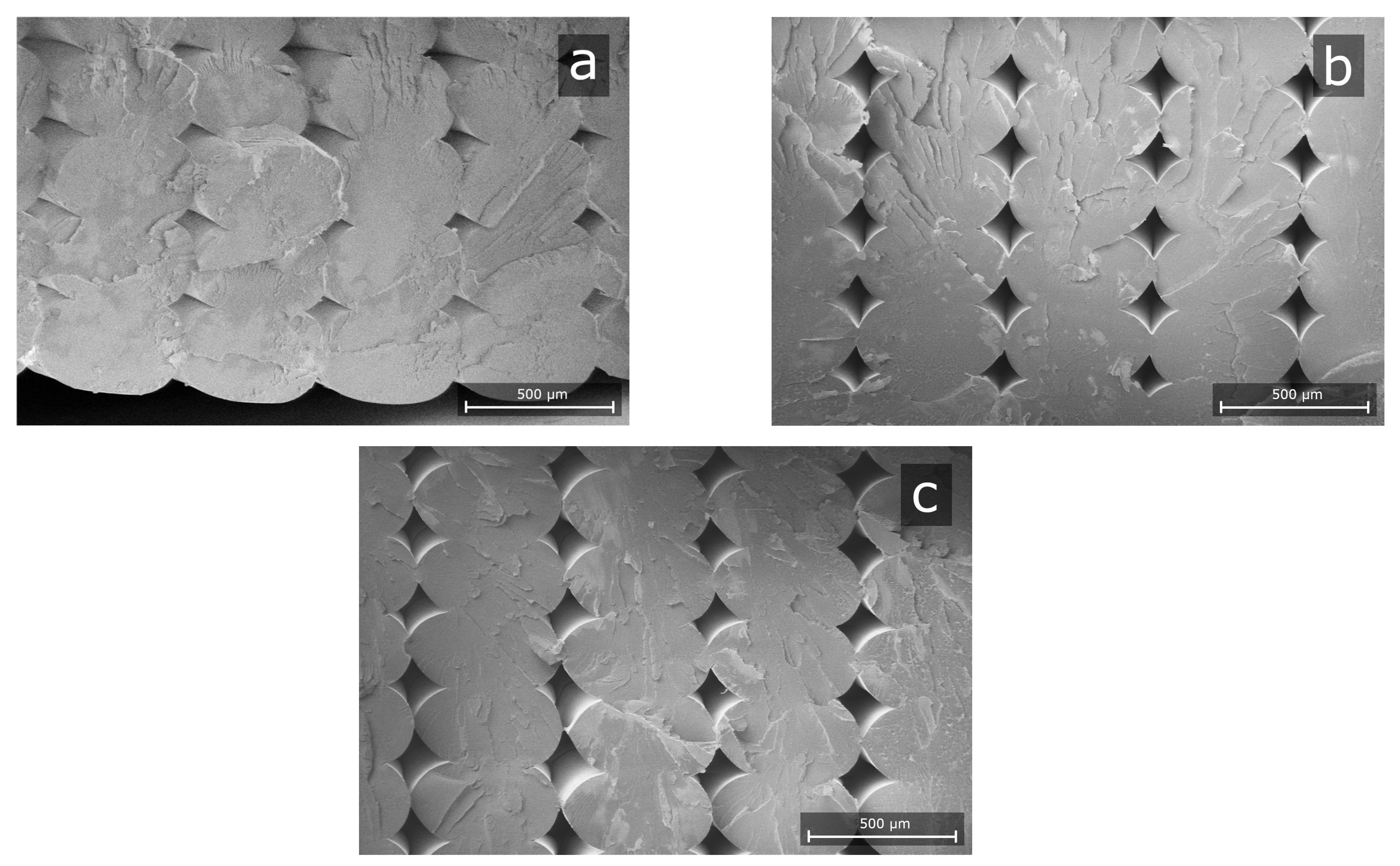
The infill density was set to 100% (solid) for all samples, and the samples were printed without a border to investigate the overall mechanical performance considering only X, Y, and Z printing directions for the rasters. The dimensions of the test specimens for both static and fatigue tests were 144 × 12.7 × 3 mm, which corresponds with the ASTM standard for flexural testing of unreinforced and reinforced plastics [41]. At least three replicants were tested to obtain statistically confident values, and the values shown on the graphs correspond to the mean value together with the standard deviation. The fracture surfaces for the transverse cross-sections of the Ultem samples printed in the X, Y, and Z directions and ruptured in liquid nitrogen were examined using a conventional complementary metal oxide semiconductor (CMOS) camera with a built-in 5× zoom lens. Images are provided in Figure 1. According to Figure 1a,b, similar void distribution in the transverse cross-sections of the fractured samples printed in the X and Y directions were revealed, indicating a similar degree of fiber-to-fiber fusion. The analysis of the morphology of samples printed in the Z direction (Figure 1c) showed that the transverse cross-section was different, revealing rough structures of extruded filaments.

2.2. Methods

2.2.1. Cooling of the Test Samples

Similarly, as reported in ref. [36] right after printing, the samples were subjected to three different cooling conditions: cooling in the printer from 180 to 45 °C for 4 h (P); rapid removal from the printer and cooling in the oven from 200 to 45 °C during 4 h (O); and removal from the printer and cooling at room temperature (R). The internal dimensions of the printer and oven were 1.6 × 1.2 × 1 m3 and 1.14 × 0.8 × 0.94 m3, respectfully. The change in temperature for the samples during all cooling conditions was provided and discussed in detail in a previous paper [36]. Though the cooling in the oven was simulated according to the printer’s thermal conditions, the temperature evolution vs. time was slower than in the printer where the samples were subjected to free cooling conditions. Lastly, fast cooling in approx. 5 min was registered for cooling at room temperature conditions.

2.2.2. Morphological Analysis

Thermo Scientific’s Helios 5 UX high-resolution SEM-FIB electron microscope (Waltham, MA, USA) was used to evaluate the morphology of the Ultem samples printed in the X, Y, and Z directions. The microscope was operated at 0.5 kV and 13 pA with scan interlacing and integration to prevent charging. The images were obtained with Everhart–Thornley (ETD) and ion conversion and electron (ICE) detectors operated in secondary electron detection mode. The specimens were imaged after mechanical testing without further modification. The fracture surface of the samples printed in the X, Y, and Z directions having different thermal cooling histories was analyzed by employing SEM.

2.2.3. Static Bending Tests

The static tests were carried out with the aid of three-point bending tests in line with ASTM D790 at room temperature [41]. A programmable material testing device and its related software [42] developed in the Institute of Solid State Physics were employed in the three-point bending mode configuration. Torque was generated by a Nema 23 (23HS9430) stepper motor controlled by DM542A. Torque was further amplified by a 1 to 10 planetary gear set. A rigid coupler connects the gearsets shaft to a ball screw. A 3D-printed structural element was mounted to a screw nut on the lead screw and a ball-bearing cart on a linear guideway. The structural element was outfitted with a cylindrical screw head with a diameter of 12 mm and a width of 19 mm which bends the sample. The setup is equipped with a strain sensor (DYLF-102), signal amplifier and stabilizer (DY510), and a programmable multimeter (HM8012). The measurement apparatus employs an analog multimeter that registers the electrical tension generated. The tests involved measuring the flexural strength and elongation at break with the rate of crosshead motion of R = 1.3 mm/min, according to the formula [41]:
R = Z L 2 6 d
where L is the support span (48 ± 0.1 mm), Z is the rate of straining of the outer fiber (Z should be 0.01 mm/mm/min), and d is the thickness of the samples (3 ± 0.1 mm).
The measurement device employs an analog multimeter that registers the electrical tension generated. To transform the acquired voltage to kg, a coefficient equal to −62.70015 was applied. The stress (in Pa) was calculated by using the formula for the stress in the outer surface of the sample at the midpoint [41]
σ f = 3 F L 2 b d 2
where F is the load at a given point on the load–deflection curve and b is the width of the sample (12.78 ± 0.02 mm).
The flexural strain εf (in %), i.e., the nominal fractional change in the length for the outer surface of the test specimen at midspan, where the maximum strain occurs, can be either calculated accordingly [38]:
ε f = 6 D d L 2 × 100 ,
where D is the maximum deflection of the center of the sample.
The flexural modulus was obtained by using stress–strain curves and evaluating the slope of a secant line for the strains 0.05% and 0.25%. The flexural strength of the samples obtained for different printing directions was used as a reference characteristic for performing fatigue tests.

2.2.4. Fatigue Tests

The displacement-controlled fatigue tests in three-point bending were performed by using the same programmable material testing device as for static bending tests. Based on the results obtained for the static tests, the maximal flexural stress (σmax) was found for all printing directions. The flexural strain was evaluated and applied for the stress ratios such as 75% and 50% of σmax. Due to the characteristics of the testing device, the bending load was applied in displacement control, at approx. 0.2 Hz frequency. As stated in [29], high loading frequency causes internal heating in plastic, thus affecting the fatigue behavior of FFF parts. Therefore, low frequency is advantageous and allows for minimizing internal heating. All tests were performed at room temperature. The bipolar strain gauge drifted by 0.05% (manufacturers claim) an hour. The baseline (constant calibration coefficient) was taken before every measurement. The cyclic strain was always measured in a way that the sample is unstressed at the end of every cycle. Stress calculation was automated and a prominence of 0.05 was employed, overflow values were culled from the dataset. The required stress was periodically applied with stepper motor steps as the X axis until the loss of structural integrity. Five cycles of the displacement-controlled fatigue test at 75% of σmax performed for the Y printing direction are shown in Figure 2, the length of the test consists of hundreds of cycles.

3. Results

3.1. Morphological Analysis

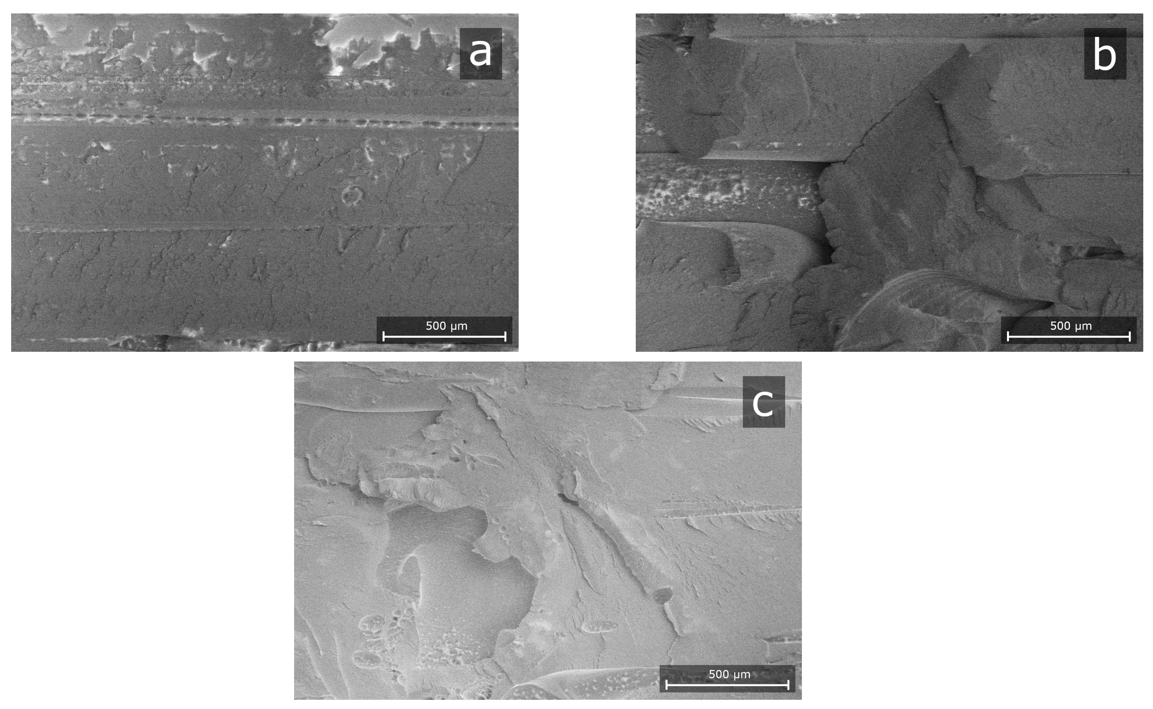
The morphology of the fracture surface for the transverse cross-section of Ultem samples printed in all printing directions was analyzed by SEM, and the results obtained for the printing directions X, Y, and Z after subjecting to different cooling conditions are provided in Figure 3, Figure 4 and Figure 5, accordingly. According to Figure 3, the thermal cooling history of the Ultem samples did not lead to large differences in the morphology of the fracture surface for the Ultem samples printed in the X direction. The most obvious failure mode in the X direction was crazing which is represented by interconnected void arrays resulting in microcracking of fibrils, and further propagation ends with a macrocracking failure [1,28].
For the Y printing direction (Figure 4), both crazing (Figure 4a) and delamination (Figure 4b,c) were observed with progressive crack propagation in a bulk material direction [28]. For the samples cooled in the printer, these effects were minimal indicating better thermodynamic conditions in comparison with the rest of the cooling regimes. Finally, the samples printed in the Z direction (see Figure 5a–c) were also characterized by multiple failure modes such as crazing and delamination. Again, the least effects were observed for the cooling conditions in the printer indicating the most thermodynamically stable regime and as a result the highest mechanical properties similarly as discussed in [36].

3.2. Static 3-Point Bending Tests

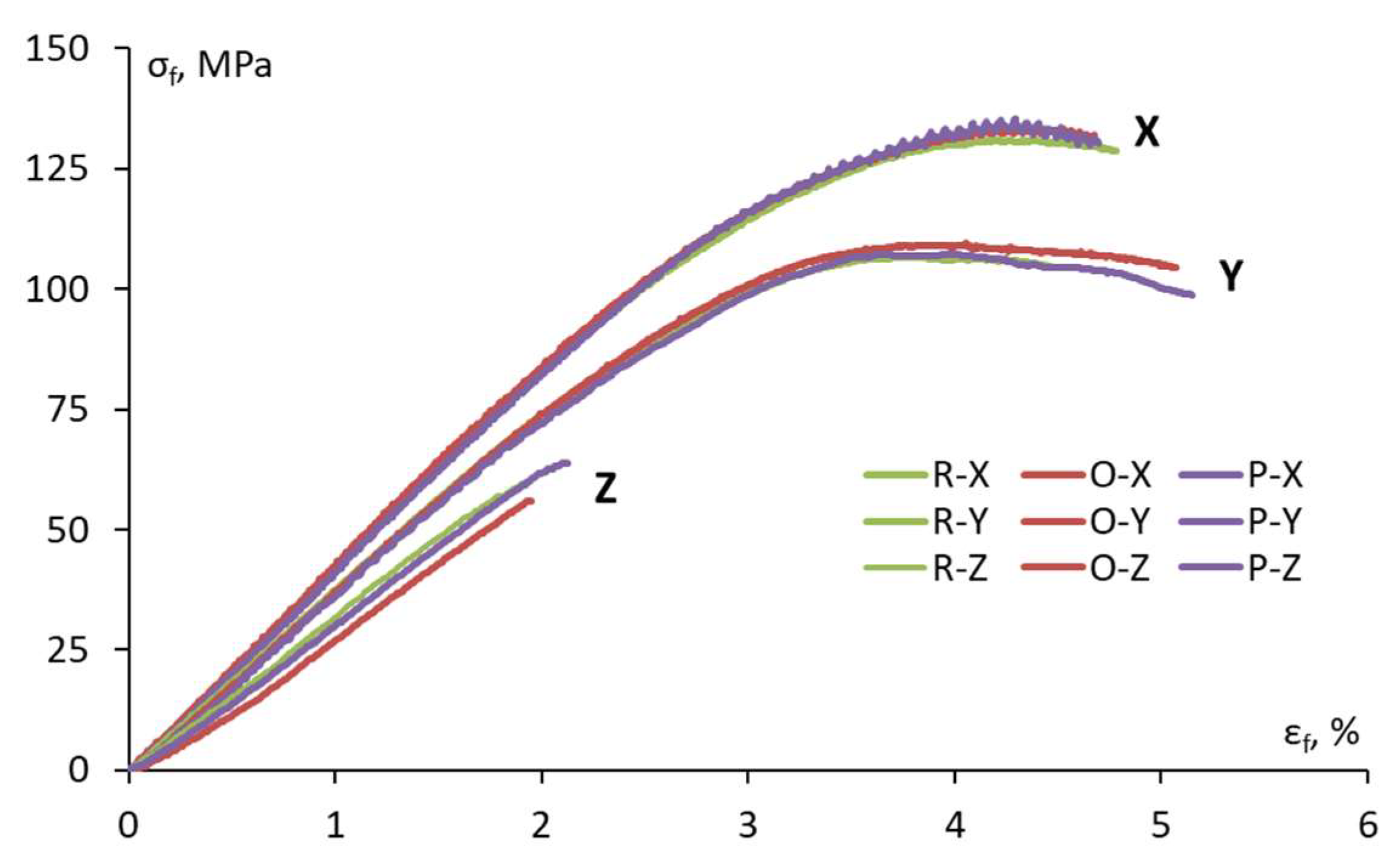
The representative stress–strain curves for Ultem samples printed in different directions and subjected to cooling in the printer (P), oven (O), and at room temperature (R) are provided in Figure 6. It is obvious that the mechanical performance was almost the same for the same printing direction (X, Y, or Z) but varied significantly for different printing directions. Based on the stress–strain diagrams shown in Figure 6, the flexural strength and modulus, and maximal deformation were evaluated. The results obtained are summarized in Figure 7. Obviously, as for the tensile properties which were reported previously [36], all static flexural characteristics are direction-dependent but not post-printing conditions dependent. Thus, for samples printed in X and Y directions, the failure was more ductile in comparison with the Z printing direction characterized by brittle failure. No significant effect of the post-printing conditions on the flexural characteristics could be attributed to similar morphological peculiarities and failure modes for the samples printed in the same direction which were revealed in Figure 3, Figure 4 and Figure 5 and hypothetically to similar inter- and intralayer adhesion.
According to Figure 7, the highest flexural strength and modulus, as well as maximal strain were observed for the X printing direction, while the lowest was for the Z direction. Interestingly, for different cooling conditions, almost no change was revealed for the same printing direction. Similarly, as in [35], the printing orientation had a crucial role in the flexural behavior of the specimens, as stress was normal to the specimen section and the orientation of the bonding area between rasters defined the way the material resisted the stress. Thus, the relative change for the X direction if compared to the Y direction for the flexural strength was 20–24% and the flexural modulus by 10–15%, while for the maximal strain, it was lower by 0.1–1.18%. When subjected to a flexural load, the upper surface of a specimen undergoes compression, while the lower surface experiences tension. For X-direction specimens, the extruded filaments are perpendicular to the direction of load application which increases the resistance of the specimen. However, for Y-direction samples, the two load-bearing surfaces are primarily composed of infill which reduces the maximum load that the samples can withstand [43].
For the Z direction, both flexural strength and maximal strain were almost twice lower and the flexural modulus was reduced by 40–44% if compared with the X printing direction for the test samples subjected to all cooling conditions. This occurs because the Z-direction samples have intra-layer filaments parallel to the stress plane [44]. Therefore, the results indicate that the bending performance of the 3D-printed samples is lower when the intra-layer unions resist the stress.

3.3. Fatigue Tests

Bending fatigue tests differ from uniaxial fatigue tests in several aspects [45]. The bending moment applied on the specimen is linear along its length leading to variations in the distribution of stresses, strains, and damage along the gauge length of the specimen. Conversely, in tension–compression fatigue experiments, the stresses, strains, and damage are assumed to be uniform in each cross-section of the specimen. Moreover, because of continuous stress redistribution, the neutral fiber (as defined in classical beam theory) undergoes displacement within the cross-section, caused by variations in damage distribution. Thus, when a particular region within the composite material moves, such as from the compressive side to the tensile side, its damage behavior undergoes significant alteration.
All displacement-controlled fatigue tests as shown in Figure 8 had two characteristic stages: (1) an almost constant value of reaction force/stress until 1000 cycles (for 75% of σmax) and 3000 cycles (for 50% of σmax), and (2) a sudden drop in the reaction force leading to the loss of structural integrity for the samples. The representative curves for the normalized stress for the Ultem samples printed in the Y direction and subjected to different cooling conditions (as indicated on the graph) over the cycles are provided in Figure 8. For the X and Z printing directions, the overall performance was similar to the results shown in Figure 8.
Similar results for the displacement-controlled fatigue tests for filled natural rubber and styrene butadiene rubber materials were discussed in [44]. Thus, the end-of-life or failure was defined to be reached if the dynamic stiffness drop cannot be associated with the material-specific viscoelastic stiffness drop anymore. Since not all samples reached the end-of-life, the number of cycles for all groups of samples at a reduction of the reaction force/stress by 10% was analyzed as schematically shown in Figure 9 for the Ultem samples subjected to 75% of σmax.
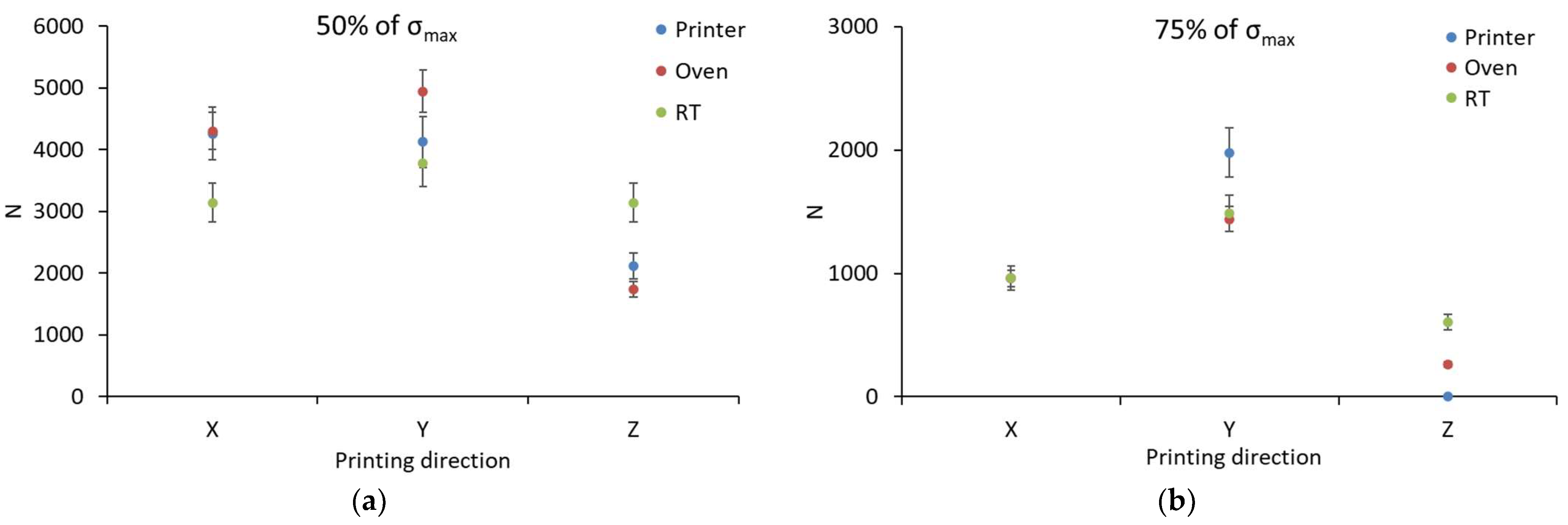
Thus, the number of cycles corresponding to a 10% reduction is summarized in Figure 10 for all printing directions and all post-printing conditions. It is interesting to note that the maximal number of cycles for the Ultem samples subjected to different cooling conditions was obtained for the Y printing direction while the lowest number of cycles was revealed for the Z printing direction. These results were the most prominent particularly in loading conditions at 75% of the flexural strength. It could be described by the anisotropy of the 3D-printed samples introduced by the FFF process which was already discussed for static bending tests. Similar results were obtained for Ultem 9085 at 40% of σmax [15], when samples printed in the X and Y directions had almost the same cycles-to-failure (8270 and 8340) while for the Z direction, the number of cycles to failure was much lower (4200), respectively. Analogously, the building orientation was found to be the most critical printing parameter affecting the fatigue life for 3D-printed ABS samples [31]. The longest fatigue life was obtained for X printed samples in comparison with XY and Y printing orientation due to the difference between the bending stress applied to differently oriented rasters and voids, thereby accelerating the crack growth and decreasing the fatigue life.
Moreover, in addition to the anisotropy of the FFF process, inter-/intra-layer adhesion or bonding could have a crucial influence on the bending performance of 3D-printed parts. For the samples printed in the Y direction the extruded ellipsoidal-shaped filaments are located along the direction of force application, thus having more contact areas between the layers than for the samples printed in the X direction. Therefore, a larger contact area hypothetically led to stronger intra-layer bonding and as a result a better mechanical performance [28,46].
Most of the results for the X and Y printing directions shown in Figure 10 revealed that the Ultem samples subjected to the cooling conditions in the printer and the oven had a similar number of cycles while a lower number of cycles was obtained for the cooling at room temperature. Opposite results were revealed for the Z printing direction when for the samples cooled at room temperature the highest number of cycles was revealed. It should be noted that the samples printed in the Z direction were printed with minimal side walls which were cut before the tests but still could affect the testing results. Moreover, usually, fatigue data for 3D-printed polymer parts are scattered owing to the manufacturing defects and uncertainty in the FFF process, which complicates the overall data analysis [27].

4. Conclusions

In this study, an experimental analysis of static and fatigue bending characteristics of Ultem 9085 samples was carried out. The test samples were manufactured by using FFF in different printing directions and subjected to different post-printing conditions, cooling in the printer and the oven in similar thermal regimes, and rapid cooling at room temperature.
No meaningful difference for cooling in the printer and oven in both static and fatigue characteristics of Ultem 9085 for the X and Y printing was revealed. The relative change for the X direction if compared to the Y direction for the flexural strength was 20–24%, for the flexural modulus by 10–15%, while for the maximal strain, it was lower by 0.1–1.18%. Moreover, for the X and Y printing directions, Ultem samples subjected to the cooling conditions in the printer and the oven had a similar number of cycles while a lower number of cycles was obtained for the cooling at room temperature. For the Z-direction samples subjected to any cooling regime, the lowest bending performance was found since they have intra-layer filaments parallel to the stress plane.
According to SEM analysis, the thermal cooling history did not lead to large differences in the morphology of the fracture surface for the Ultem samples printed in the X and Y directions. In the X direction, the most obvious failure mode was crazing, while for the Y and Z printing directions both crazing and delamination were observed. Moreover, for the Y and Z printing directions, the samples cooled in the printer were characterized by minimal roughness and delamination indicating better thermodynamic conditions in comparison with the rest cooling regimes.
Considering the lowest bending performance obtained for the Ultem samples printed in the Z direction, it could be recommended to control the anisotropic static and fatigue bending characteristics of the FFF printed parts using optimized printing parameters/directions.
Based on the results obtained, it could be concluded that cooling in the oven at similar thermal conditions did not significantly affect both static and fatigue bending properties of Ultem 9085 3D-printed samples. It means that this cooling regime could be effectively applied allowing significant time-savings for industrially applied 3D printers.

Author Contributions

The study concept was devised by D.D.; methodology, validation, and formal analysis were carried out by D.D., J.J. and T.G.-K.; investigation, resources, and data curation were performed by A.Z., E.E., E.V. and T.G.-K.; writing—original draft preparation was performed by T.G.-K., P.-P.K., A.Z. and E.E.; supervision was performed by D.D.; project administration was performed by D.D. and J.J. All authors have read and agreed to the published version of the manuscript.

Funding

This research was funded by the European Regional Development Fund within Measure 1.1.1.1 “Industry-Driven Research” of the Specific Aid Objective 1.1.1 “To increase the research and innovation capacity of scientific institutions of Latvia and their ability to attract external funding by investing in human resources and infrastructure” of the Operational Program “Growth and Employment” (Project No. 1.1.1.1/20/A/188). T.G.-K. is grateful to COST Action CA21155—Advanced Composites under High Strain Rates loading: a route to certification-by-analysis (HISTRATE). A.Z., E.E., and E.V. are grateful for funding received from the European Union Horizon 2020 Framework program H2020-WIDESPREAD-01-2016-2017-TeamingPhase2 under grant agreement No. 739508, project CAMART2.

Data Availability Statement

The data presented in this study are available on request from the corresponding author.

Acknowledgments

Not applicable.

Conflicts of Interest

The authors declare no conflict of interest.

References

  1. Daminabo, S.C.; Goel, S.; Grammatikos, S.A.; Nezhad, H.Y.; Thakur, V.K. Fused deposition modeling-based additive manufacturing (3D printing): Techniques for polymer material systems. Mater. Today Chem. 2020, 16, 100248. [Google Scholar] [CrossRef]
  2. Joshi, S.C.; Sheikh, A.A. 3D printing in aerospace and its long-term sustainability. Virtual Phys. Prototyp. 2015, 10, 175–185. [Google Scholar] [CrossRef]
  3. Kanishka, K.; Acherjee, B. A systematic review of additive manufacturing-based remanufacturing techniques for component repair and restoration. J. Manuf. Process. 2023, 89, 220–283. [Google Scholar] [CrossRef]
  4. Kantaros, A.; Soulis, E.; Ganetsos, T.; Petrescu, F.I.T. Applying a combination of cutting-edge industry 4.0 processes towards fabricating a customized component. Processes 2023, 11, 1385. [Google Scholar] [CrossRef]
  5. Jandyal, A.; Chaturvedi, I.; Wazir, I.; Raina, A.; Haq, M.I.U. 3D printing—A review of processes, materials and applications in industry 4.0. Sustain. Oper. Comput. 2022, 3, 33–42. [Google Scholar] [CrossRef]
  6. Singh, T.; Kumar, S.; Sehgal, S. 3D printing of engineering materials: A state of the art review. Mater. Today Proc. 2020, 28, 1927–1931. [Google Scholar] [CrossRef]
  7. Wu, Y.; Fang, J.; Wu, C.; Li, C.; Sun, G.; Li, Q. Additively manufactured materials and structures: A state-of-the-art review on their mechanical characteristics and energy absorption. Int. J. Mech. Sci. 2023, 246, 108102. [Google Scholar] [CrossRef]
  8. Kantaros, A.; Ganetsos, T.; Piromalis, D. 3D and 4D printing as integrated manufacturing methods of industry 4.0. Am. J. Eng. Appl. Sci. 2023, 16, 12–22. [Google Scholar] [CrossRef]
  9. Shahrubudin, N.; Lee, T.C.; Ramlan, R. An overview on 3D printing technology: Technological, materials, and applications. Procedia Manuf. 2019, 35, 1286–1296. [Google Scholar] [CrossRef]
  10. Oropallo, W.; Piegl, L.A. Ten challenges in 3D printing. Eng. Comput. 2016, 32, 135–148. [Google Scholar] [CrossRef]
  11. Kantaros, A.; Diegel, O.; Piromalis, D.; Tsaramirsis, G.; Khadidos, A.O.; Khadidos, A.O.; Khan, F.Q.; Jan, S. 3D printing: Making an innovative technology widely accessible through makerspaces and outsourced services. Mater. Today Proc. 2022, 49, 2712–2723. [Google Scholar] [CrossRef]
  12. Lee, J.-Y.; An, J.; Chua, C.K. Fundamentals and applications of 3D printing for novel materials. Appl. Mater. Today 2017, 7, 120–133. [Google Scholar] [CrossRef]
  13. Doshi, M.; Mahale, A.; Singh, S.K.; Deshmukh, S. Printing parameters and materials affecting mechanical properties of FDM-3D printed Parts: Perspective and prospects. Mater. Today Proc. 2022, 50, 2269–2275. [Google Scholar] [CrossRef]
  14. Patel, R.; Desai, C.; Kushwah, S.; Mangrola, M.H. A review article on FDM process parameters in 3D printing for composite materials. Mater. Today Proc. 2022, 60, 2162–2166. [Google Scholar] [CrossRef]
  15. Fischer, M. and Schöppner V. Fatigue behavior of FDM parts manufactured with Ultem 9085. JOM 2017, 69, 563–568. [Google Scholar] [CrossRef]
  16. Harris, M.; Potgieter, J.; Archer, R.; Arif, K.M. Effect of material and process specific factors on the strength of printed parts in fused filament fabrication: A review of recent developments. Materials 2019, 12, 1664. [Google Scholar] [CrossRef] [PubMed] [Green Version]
  17. Zīle, E.; Zeleniakiene, D.; Aniskevich, A. Characterization of polylactic acid parts produced using fused deposition modelling. Mech. Compos. Mater. 2022, 58, 169–180. [Google Scholar] [CrossRef]
  18. Popescua, D.; Zapciua, A.; Amzab, C.; Baciuc, F.; Marinescu, R. FDM process parameters influence over the mechanical properties of polymer specimens: A review. Polym. Test. 2018, 69, 157–166. [Google Scholar] [CrossRef]
  19. Gebisa, A.W.; Lemu, H.G. Investigating effects of fused-deposition modeling (FDM) processing parameters on flexural properties of ULTEM 9085 using designed experiment. Materials 2018, 11, 500. [Google Scholar] [CrossRef] [Green Version]
  20. Deng, X.; Zeng, Z.; Peng, B.; Yan, S.; Ke, W. Mechanical properties optimization of poly-ether-ether-ketone via fused deposition modeling. Materials 2018, 11, 216. [Google Scholar] [CrossRef] [Green Version]
  21. Safai, L.; Cuellar, J.S.; Smit, G.; Zadpoor, A.A. A review of the fatigue behavior of 3D printed polymers. Addit. Manuf. 2019, 28, 87–97. [Google Scholar] [CrossRef]
  22. D’Amore, A.; Califano, A.; Grassia, L. Modelling the loading rate effects on the fatigue response of composite materials under constant and variable frequency loadings. Int. J. Fatigue 2021, 150, 106338. [Google Scholar] [CrossRef]
  23. ASTM E606/E606M-21; Standard Test Method for Strain-Controlled Fatigue Testing. 2021. Available online: https://www.astm.org/e0606_e0606m-21.html (accessed on 23 March 2023).
  24. ASTM D3479/D3479M-19; Standard Test Method for Tension-Tension Fatigue of Polymer Matrix Composite Materials. 2019. Available online: https://www.astm.org/d3479_d3479m-19.html (accessed on 23 March 2023).
  25. ISO 13003:2003; Fibre-Reinforced Plastics—Determination of Fatigue Properties under Cyclic Loading Conditions. 2019. Available online: https://www.iso.org/standard/32190.html (accessed on 23 March 2023).
  26. Kluczynski, J.; Szachogłuchowicz, I.; Torzewski, J.; Sniezek, L.; Grzelak, K.; Budzik, G.; Przeszłowski, L.; Małek, M.; Łuszczek, J. Fatigue and fracture of additively manufactured polyethylene terephthalate glycol and acrylonitrile butadiene styrene polymers. Int. J. Fatigue 2022, 165, 107212. [Google Scholar] [CrossRef]
  27. Frascio, M.; Avalle, M.; Monti, M. Fatigue strength of plastics components made in additive manufacturing: First experimental results. Procedia Struct. Integr. 2018, 12, 32–43. [Google Scholar] [CrossRef]
  28. Dolzyk, G.; Jung, S. Tensile and fatigue analysis of 3D-printed polyethylene terephthalate glycol. J. Fail. Anal. Prev. 2019, 19, 511–518. [Google Scholar] [CrossRef]
  29. Bakhtiari, H.; Aamir, M.; Tolouei-Rad, M. Effect of 3D printing parameters on the fatigue properties of parts manufactured by fused filament fabrication: A review. Appl. Sci. 2023, 13, 904. [Google Scholar] [CrossRef]
  30. Shanmugam, V.; Das, O.; Babu, K.; Marimuthu, U.; Veerasimman, A.; Johnson, D.J.; Neisiany, R.E.; Hedenqvist, M.S.; Ramakrishna, S.; Berto, F. Fatigue behaviour of FDM-3D printed polymers, polymeric composites and architected cellular materials. Int. J. Fatigue 2021, 143, 106007. [Google Scholar] [CrossRef]
  31. He, F.; Khan, M. Effects of printing parameters on the fatigue behaviour of 3D-printed ABS under dynamic thermo-mechanical loads. Polymers 2021, 13, 2362. [Google Scholar] [CrossRef]
  32. Ziemian, C.W.; Ziemian, R.D.; Haile, K.V. Characterization of stiffness degradation caused by fatigue damage of additive manufactured parts. Mater. Des. 2016, 109, 209–218. [Google Scholar] [CrossRef] [Green Version]
  33. Afrose, M.F.; Masood1, S.H.; Iovenitti, P.; Nikzad, M.; Sbarski, I. Effects of part build orientations on fatigue behaviour of FDM-processed PLA material. Prog Addit Manuf 2016, 1, 21–28. [Google Scholar] [CrossRef]
  34. Sood, A.K.; Ohdar, R.K.; Mahapatra, S.S. Parametric appraisal of mechanical property of fused deposition modelling processed parts. Mater. Des. 2010, 31, 287–295. [Google Scholar] [CrossRef]
  35. Travieso-Rodriguez, J.A.; Jerez-Mesa, R.; Llumà, J.; Traver-Ramos, O.; Gomez-Gras, G.; Rovira, J.J.R. Mechanical properties of 3D-printing polylactic acid parts subjected to bending stress and fatigue testing. Materials 2019, 12, 3859. [Google Scholar] [CrossRef] [Green Version]
  36. Glaskova-Kuzmina, T.; Dejus, D.; Jātnieks, J.; Aniskevich, A.; Sevcenko, J.; Sarakovskis, A.; Zolotarjovs, A. Effect of post-printing cooling conditions on the properties of ULTEM printed parts. Polymers 2023, 15, 324. [Google Scholar] [CrossRef]
  37. Stratasys Inc., in Ultem 9085 (Product Information, 2023). Available online: https://www.stratasys.com/en/materials/materials-catalog/fdm-materials/ultem-9085 (accessed on 4 March 2023).
  38. Lv, Y.; Dejus, D.; Kobenko, S.; Singamneni, S.; Glaskova-Kuzmina, T. Evaluation of the fire-retardancy of ULTEM 9085 polymer composites processed by fused deposition modelling. Mater. Sci. 2022, 28, 353–359. [Google Scholar] [CrossRef]
  39. Kobenko, S.; Dejus, D.; Jātnieks, J.; Pazars, D.; Glaskova-Kuzmina, T. Structural integrity of the aircraft interior spare parts produced by additive manufacturing. Polymers 2022, 14, 1538. [Google Scholar] [CrossRef]
  40. Byberg, K.I.; Gebisa, A.W.; Lemu, H.G. Mechanical properties of ULTEM 9085 material processed by fused deposition modeling. Polym. Test. 2018, 72, 335–347. [Google Scholar] [CrossRef]
  41. ASTM D790-17; Standard Test Methods for Flexural Properties of Unreinforced and Reinforced Plastics and Electrical Insulating Materials. 2017. Available online: https://www.astm.org/d0790-17.html (accessed on 4 April 2023).
  42. Einbergs, E.; Zolotarjovs, A. Programmable material testing device for mechanoluminescence measurements. HardwareX 2022, 12, e00349. [Google Scholar] [CrossRef] [PubMed]
  43. Padovano, E.; Galfione, M.; Concialdi, P.; Lucco, G.; Badini, C. Mechanical and thermal behavior of Ultem® 9085 fabricated by fused-deposition modeling. Appl. Sci. 2020, 10, 3170. [Google Scholar] [CrossRef]
  44. Forés-Garriga, A.; Pérez, M.A.; Gómez-Gras, G.; Reyes-Pozo, G. Role of infill parameters on the mechanical performance and weight reduction of PEI Ultem processed by FFF. Mater. Des. 2020, 193, 108810. [Google Scholar] [CrossRef]
  45. Van Paepegem, W.C. 16-Fatigue testing methods for polymer matrix composites. In Creep and Fatigue in Polymer Matrix Composites; Guedes, R.M., Ed.; Elsevier, Woodhead Publishing: Oxford, UK, 2011; pp. 461–491. ISBN 9780081014585. [Google Scholar]
  46. Coasey, K.; Hart, K.R.; Wetzel, E.; Edwards, D.; Mackay, M.E. Nonisothermal welding in fused filament fabrication. Addit. Manuf. 2020, 33, 101140. [Google Scholar] [CrossRef]
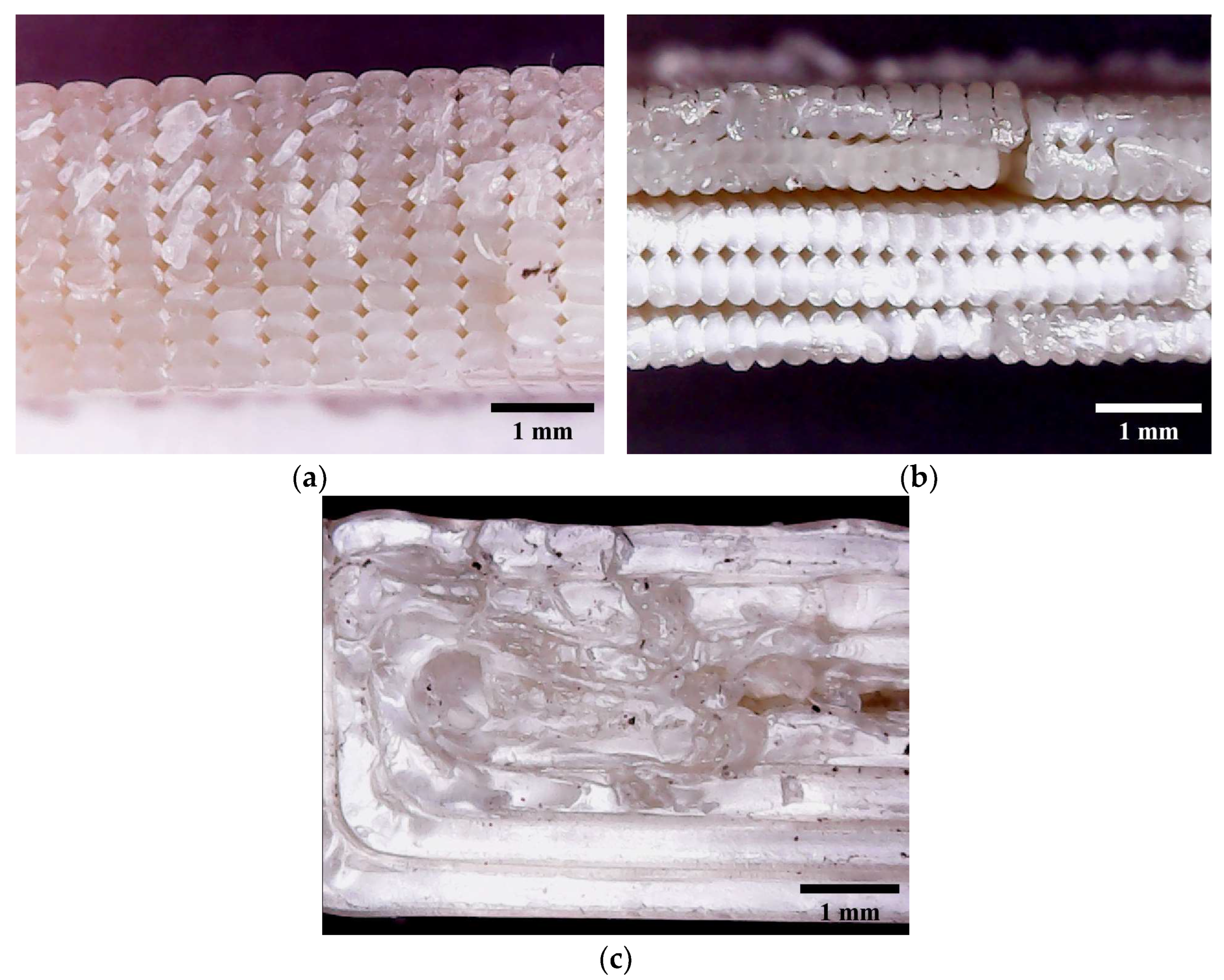
Figure 1. Transverse cross-sections of fractured Ultem samples after cooling in an oven are printed in X (a), Y (b), and Z (c) directions and studied by optical microscopy.
Jcs 07 00316 g001
Figure 2. Five cycles of the displacement-controlled fatigue test for Ultem samples printed in the Y direction at 75% of σmax.
Jcs 07 00316 g002
Figure 3. Transverse cross-sections of Ultem samples printed in the X direction after cooling in the printer (a), oven (b), and at room temperature (c) were studied by SEM.
Jcs 07 00316 g003
Figure 4. Transverse cross-sections of Ultem samples printed in the Y direction after cooling in the printer (a), oven (b), and at room temperature (c) were studied by SEM.
Jcs 07 00316 g004aJcs 07 00316 g004b
Figure 5. Transverse cross-sections of Ultem samples printed in the Z direction after cooling in the printer (a), oven (b), and at room temperature (c) were studied by SEM.
Jcs 07 00316 g005
Figure 6. Stress–strain curves of Ultem samples printed in the X, Y, and Z directions and subjected to cooling in the printer (P), oven (O), and at room temperature (R).
Jcs 07 00316 g006
Figure 7. Flexural strength (a), maximal flexural strain (b), and flexural modulus (c) of Ultem samples printed in different directions (after cooling in the printer (P), oven (O), and at room temperature (R)).
Jcs 07 00316 g007aJcs 07 00316 g007b
Figure 8. Measured reaction stress normalized to the flexural strength over cycles for Ultem samples printed in Y direction and subjected to cooling in the printer (P), oven (O), and at room temperature (R). Loading conditions correspond to 50% of σmax.
Jcs 07 00316 g008
Figure 9. Measured reaction stress normalized to the initial stress over cycles for Ultem samples printed in the X direction and subjected to cooling in the printer (P), oven (O), and at room temperature (R). Loading conditions correspond to 75% of σmax.
Jcs 07 00316 g009
Figure 10. The number of cycles corresponding to the reduction of reaction force by 10% for Ultem samples printed in different directions and subjected to different cooling conditions (indicated on the graph). The loading conditions correspond to 50% (a) and 75% (b) of σmax.
Jcs 07 00316 g010
Disclaimer/Publisher’s Note: The statements, opinions and data contained in all publications are solely those of the individual author(s) and contributor(s) and not of MDPI and/or the editor(s). MDPI and/or the editor(s) disclaim responsibility for any injury to people or property resulting from any ideas, methods, instructions or products referred to in the content.