Article

Effect of Surface Coating and Plasma Treatment on Mechanical Properties of Wood Plastic Composites

1
Graduate School of Sciences and Technology for Innovation, Yamaguchi University, Ube 755-8611, Japan
2
Development Division, Renias Co., Ltd., Mihara 729-0473, Japan
3
Department of Mechanical Engineering, Yamaguchi University, Ube 755-8611, Japan
*
Author to whom correspondence should be addressed.
J. Compos. Sci. 2023, 7(7), 296; https://doi.org/10.3390/jcs7070296
Submission received: 19 May 2023 / Revised: 10 July 2023 / Accepted: 13 July 2023 / Published: 17 July 2023

Abstract

:
Mechanical properties of plasma-irradiated and surface-coated wood plastic composites (WPCs) have been investigated in this paper. WPCs were developed by injection molding technique using wood fiber (WF) as reinforcement and polypropylene (PP) as matrix. The short, discontinuous WF was compounded with thermoplastic PP at varying weight fractions of 0 wt%, 25 wt% (WP25), and 50 wt% (WP50) to yield tensile test specimens in accordance with JIS K7139-A32 standards. Subsequently, plasma treatment was performed on the test-pieces, followed by surface coating by immersion in acrylic resin liquid containing homogeneously dispersed TEMPO-oxidized cellulose nanofibers (CNF). The results indicate an increase in surface roughness after plasma irradiation, but surface coating of the specimens with acrylic paint and CNF decreased their surface roughness by ∼50% in comparison to the untreated specimens. Plasma treatment and surface coating also increased the tensile strength of neat PP, WP25 and WP50 specimens by 5.4–7.1%, 3.5–3.7% and 3.0–3.6%, respectively, whereas their fracture strains tended to decrease. Compared to the untreated specimens, the surface-coated specimens generally displayed higher tensile strength. This finding is a corroboration that the observed increase in strength is highly contingent on the adhesion between the specimen surface and the coating layer than on the improvement in surface roughness. Thus, it is inferable that surface coating could be of great importance in enhancing the mechanical performance of WPCs.

1. Introduction

Presently, many plastics are used all over the world as indispensable materials for daily life. Among them are composite materials made from a combination of two or more constituents namely: resin, as the base material (matrix), and fiber, as the reinforcing material [1]. Further to the characteristics of plastics such as light weight and high molding freedom [2,3], fiber reinforced plastics (FRPs) are widely used due to their high rigidity and high strength characteristics [4,5]. Among the FRPs, glass fiber reinforced plastics (GFRPs) and carbon fiber reinforced plastics (CFRPs) which utilize glass and carbon fibers, respectively, as reinforcing materials are prevalent. GFRPs and CFRPs have excellent specific strength and rigidity, hence their application in a wide range of disciplines such as sporting goods, industrial equipment, military, marine, automobile and aircraft industries [2,6,7]. Notwithstanding the excellent mechanical properties exhibited by FRPs, their non-biodegradability and chemical stability pose an environmental threat at their time of disposal [1,8,9]. Consequently, there is an ongoing research the world over, on how to recycle FRPs and develop environmentally friendly composite materials, namely green composites and bio-composites, by using natural resources as substitutes for petroleum-based raw materials.
Green transformation of the construction and manufacturing industry is contingent on the eco-friendliness of raw materials [10]. Since green composites comprise biodegradable resins or thermoplastic resins as matrices, and biodegradable fibers like natural fibers or biomass-derived fibers as reinforcements, their integration in manufacturing is crucial in lowering the carbon footprint of the built environment [11,12]. Suitable reinforcements for green composites include wood fibers derived from waste wood and thinned wood raw materials [13], whilst industrial waste plastics are appropriate for use as base materials. Wood fiber, otherwise called wood flour owing to its finely divided particles approximating those of cereal flours in size, appearance, and texture, has a high modulus of rigidity and low thermal expansion [14]. On the other hand, discarded industrial thermoplastic resins and pure resins are highly recyclable, durable, water resistant, and moldable [15]. By combining these two elements, the resulting WPC exhibits excellent synergistic properties that compensate for the weaknesses of both wood and plastic [16].
The demand for WPCs as an alternative to plastic technology has been increasing exponentially since its utility was recognized. In 2019, the global market size of WPCs was $ 4.77 billion, and it was envisaged to reach $ 8.76 billion by 2022, and $ 9.03 billion by 2027. The cumulative annual growth rate during this forecast period was 8.57% [17]. As of 2022, the projected global market volume was 8 million tons [18,19]. Based on this promising trend, and with the increasing discovery of WPC strength enhancement techniques to guarantee their suitability for broader applications, it can only be anticipated that this demand will continue to rise. Hitherto, significant effects on mechanical properties of WPCs have been achieved through the optimization of raw material ratios and the addition of modifiers such as coupling agents and compatibilizers, which are carefully chosen based on the type of material and conditions of use. However, recent preliminary discoveries have shown that incorporating nanomaterials can enhance the compactness of WPCs by filling the gaps between the fibers, hence significantly boosting its mechanical properties. Although carbon nanotube, nano-titanium dioxide, nano-silicon dioxide and nano-calcium acid are among the nanomaterials tested so far, future prospects will involve the exploration of green nanomaterials for possible application in WPC production. This is viewed to be a timely research and a paradigm shift that will help in combating plastic waste and promoting the wider utilization of WPCs in engineering applications [14].
Prominent among the biomass and biodegradable fibers currently under investigation are cellulose nanofibers (CNF), alternatively known as cellulose nanofibrils. These are extra thin cellulose fibers made from wood-derived fiber (pulp) defibrated to the nano-scale of several hundredths of a micrometer or even smaller [20]. CNF is the world’s cutting-edge biomass material whose production process and disposal has a low impact on the environment because it is derived from plant fibers. Some of its exceptional characteristics comprise lightweight, high specific area, high elastic modulus comparable to aramid fiber, and thermal expansion rate on par with glass [21,22]. Additionally, CNF membranes manifest high gas impermeability with regard to oxygen and other gases. Owing to these lead characteristics, there is a great potential for the utilization of CNF in various manufacturing applications such as electronic materials, automobiles, paints, paper manufacturing, and household appliances [23,24]. As from 2014, Butterfly (Tamas Co., Ltd.), which had been focusing on CNF started developing CNF-equipped rackets in collaboration with Daio Paper Co., Ltd., a major paper manufacturer in Japan. The two companies were able to prove that the power of hitting balls can be increased by incorporating CNF on table tennis rackets. The CNF enhanced table tennis rackets [25,26], popularly known as Revordia CNF, are currently being manufactured and sold globally. The milestones achieved so far have spurred an interest to further explore the feasibility of CNF, particularly its potential to enhance mechanical properties of green composites. Therefore, this study attempts to strengthen WPCs and neat polypropylene (PP) by adding CNF to the coating resin, a procedure that has been detailed in the next section.
Mechanical characteristics of natural fibers have been extensively discussed in literature. According to Eichhorn et al. [27], lignocellulosic fibers from diverse origins exhibit mechanical characteristics that can compete favorably with glass fibers, especially when relative density is considered. To achieve optimal mechanical performance of lignocellulosic fiber reinforced composites, attention must be paid to the processing techniques used such as material formulation and preliminary treatment of constituent elements. In particular, mechanical properties of WPCs are known to depend on the content of wood fiber, type of matrix, and processing parameters. Based on current literature, pre-treatment procedures such as fiber surface modification, flame retardancy, compatibilization, and addition of coupling agents to the matrix elements have been successfully used to improve the mechanical performance of WPCs [14]. Be that as it may, the prospects of surface treatment as a means of improving the mechanical performance of composites is yet to be fully investigated. State of the art surface coating of plastics are aimed at improving weather resistance, decoration, rust prevention, wear resistance, and imparting electrical and glossy properties [28]. However, hitherto, it has not been fully clarified whether surface coating has a positive or negative effect on the strength of plastics and composites.
Surface modification has been used to alter the composition and structure of the hydrophobic PP, making it easier to bond with the coating material [29,30]. Typical surface modification mechanisms applied to polymer materials include chemical processing methods such as chemical treatment, coupling agent treatment, steam treatment and surface grafting; or physical processing methods such as UV irradiation, ozonation, and plasma treatment [31]. Friedrich et al. [32] tried UV irradiation and ozonation on PP, polyethylene (PE), and polyethylene terephthalate (PET). In their study, they conducted low-pressure oxygen plasma treatment and corona treatment to compare their influence on adhesion properties and surface energy of the polymer surfaces. Their results showed that low pressure plasma at the rate of 17 J mol 1 was most efficient in increasing the surface energy to 65 mN m 1 , a value higher than the 45 mN m 1 exhibited by corona treatment. Yáñez et al. [33] also performed surface modification on WPCs made from different polymers using an atmospheric pressure plasma jet, and studied the effect of varying the platform speed and nozzle distance on the composites’ surface characteristics. They ascertained that plasma treatment removed a large portion of the WF and exposed the resin to the surface, changing their surface chemistry and topography by forming new polar carbon moieties. As a result, adhesion properties were enhanced. Additionally, they established that surface-nozzle distance of 1 cm and platform speed of 0.5–2 m min 1 were the optimal conditions for achieving best adhesion results. Composites with inorganic fillers and low wood content yielded less surface modification after plasma treatment. Scarselli et al. [34] observed a considerable increase in the lap shear strength of polyether ether ketone and polyphenylene sulfide based composite joints after UV irradiation and atmospheric plasma treatment. According to their findings, plasma treatment worked more effectively than UV treatment. They attributed this to the capability of plasma treatment to activate the material surface, consequently increasing their free surface energies, a phenomenon not achievable with UV irradiation.
Notwithstanding the advancement of research on surface treatment of WPCs discussed above, present literature focuses more on traditional objectives such as UV protection, scratch resistance, abrasion resistance, water resistance, solvent resistance, chemical resistance, gloss properties, and thermal resistance. However, changes in mechanical properties of the material itself due to surface coating has not been extensively investigated. In this research, we developed wood fiber-polypropylene based composites at varying weight fractions, and investigated the effect of coating agent and CNF addition on surface roughness and tensile strength of the composites. In particular, we focused on the effectiveness of plasma treatment with intent to improve adhesion of the coating agent to the specimen surface.

2. Materials and Methods
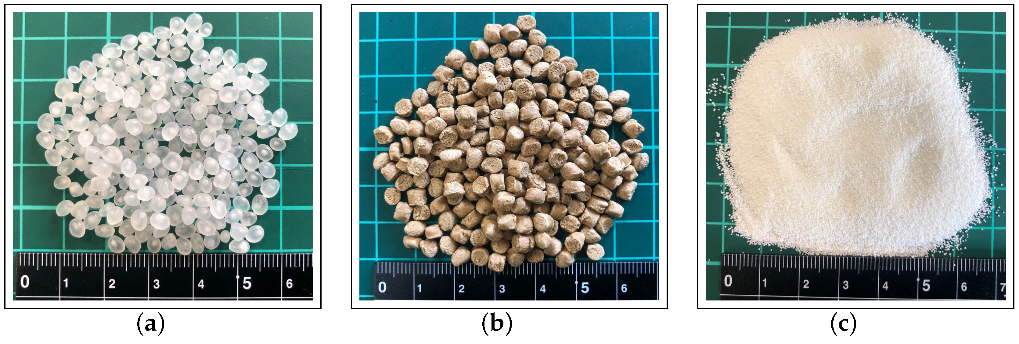
2.1. Raw Materials

The reinforcement used in this research was wood flour (WF) of 150 µm fiber length, pre-compounded with polypropylene (PP) and called masterbatch (Celbrid-N, Toclas Co., Ltd.). As matrix resin, PP (J-108 M) supplied by Prime Polymer Co., Ltd., Japan, was used together with maleic anhydride graft polypropylene (MAPP, Kayabrid 006PP-N) from Kayaku Akzo Co., Ltd., Japan, as compatibilizer. The compatibilizer was added in a ratio of 2 wt% to the matrix. The raw materials are shown in Figure 1, and the proportions of WF/PP masterbatch elements shown in Table 1 [16]. Additionally, liquid acrylic paint (SHP470-FT2050) manufactured by Momentive Inc. was mixed with PEGylated CNF to form a CNF-based suspension, which was then used as a coating agent.

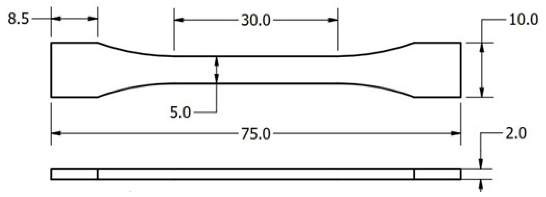
2.2. Specimen Preparation

PP pellets, WF masterbatch and MAPP elements were first compounded in a kneading machine (DS0.5-3MHB-E, Satake Chemical Machinery Industry Co., Ltd.). Three sets of PP, masterbatch, and MAPP proportions were formulated during the mixing process to yield composites with varying wood flour weight fractions of 0 wt%, 25 wt%, and 50 wt%. The kneaded material was then pulverized into small pieces of about 5 mm length using a pulverizing machine (U-280, ZI-420 type, Horai Co., Ltd.), and later molded in an injection molding machine (Babyplast 6/10P, Rambaldi & Co.) [35] at a molding temperature of 200 °C. Silicone spray (Kure Industry Co., Ltd.) was applied on the mold as a mold release agent. Standard dumbbell-type specimens were thus prepared having gauge length, width, and thickness dimensions of 30 mm, 5 mm, and 2 mm, respectively, in compliance with JIS K7139-A32 standards. Figure 2 shows the geometric model of the tensile test specimen.
After specimen fabrication, a degreaser (silicone remover, Musashi Holt Co., Ltd.) was used to remove the silicone spray from the surfaces of the specimens prior to plasma treatment and CNF coating.

2.3. Preparation of CNF Suspension in Acrylic Paint

Cellulose nanofibers having width of ∼3 nm were suspended in acrylic resin to form the coating material [36]. The CNFs were first categorized into two groups based on their lengths, i.e., short CNF, denoted by CNF-S with fiber length of 0.2–0.3 µm, and long CNF, denoted by CNF-L with fiber length of 0.7 µm. From these two categories, PEGylated CNFs were developed as per the method provided by Fujisawa et al. [37]. The CNF suspensions were first prepared at concentrations of 0.2 wt% CNF-L and 1.0 wt% CNF-S in distilled water homogenized with an ultrasonic homogenizer (US-300E, Nissei, Japan). Thereafter, the suspensions were adjusted to a pH of 2 by slowly adding 1 M HCl and stirring the mixture using a magnetic stirrer at room temperature for 30 min. Subsequently, the gelatinous CNF was collected by centrifugation and washed with 0.1 M HCl and distilled water. After exchanging the CNF suspension solvent for PGM (Propylene glycol 1-monomethyl ether, FUJIFILM Wako Pure Chemical Corp.) by centrifugation, the same mol of PEG-NH 2 (SUNBRIGHT MEPA-20H, NOF Corp.) was added to 1 mol of the carboxyl group of TEMPO-oxidized CNF (Cellenpia TC-01A, TC-02X, Nippon Paper Ind. Co.). Finally, the PGM suspension of PEG-grafted CNF was obtained by ultrasonic homogenization in ice. This was mixed with the acrylic paint to obtain the 4% solids ratio for both short and long CNF.

2.4. Plasma Treatment and Surface Coating

Since the base material (PP) is hydrophobic, specimens were irradiated with plasma on either side using a plasma treatment equipment (Japan Plasma Treat Co., Ltd.) to improve adherence of the coating resin to the surface of the test pieces. It was vital to determine the optimal processing speed and nozzle-substrate distance that would achieve maximum polarity and minimize the damage on the specimen surface. After examining various nozzle distances and plasma processing conditions, it was established that plasma processing speed of 50 mm s 1 at a nozzle-substrate distance of 5 mm yielded the highest surface polarity of 70.12 mN m 1 , in stark contrast with the 24.78 mN m 1 recorded before plasma treatment. No noticeable damage to the substrate occurred under these conditions. Furthermore, maximum reduction in water contact angle from 107.9 ° to 24.48 ° was observed, attesting to an improvement in surface adhesion. Thus, the aforementioned optimal conditions were adopted for plasma treatment. Another set of specimens was left untreated with plasma for comparison purposes. Subsequently, the specimens were dipped in three kinds of coating resins: the first one was plain acrylic paint comprising 0% CNF, while the other two were the previously prepared 4 % long and short PEGylated CNF suspensions, respectively, in acrylic paint. The coated specimens were finally placed in a constant temperature oven (manufactured by Sanyo Electric Co., Ltd., Japan) for drying at temperature and time conditions of 80 °C and 30 min, respectively. The width and thickness of each specimen were measured using a micrometer. Measurements were taken at three different locations within the gauge length before and after coating, and the average values determined. Thereafter, the coating thickness was estimated as half the difference between the specimen thickness before and after coating. Thus, for all categories of the tested samples, the coating thickness was established to be ranging from 2.4–6.0 µm, 1.9–7.4 µm, and 2.9–7.5 µm for the neat PP, WP25, and WP50 specimens, respectively.

2.5. Specimen Nomenclature

Neat PP and WF/PP specimens were designated as PP and WP, respectively. Therefore, WP25 and WP50 refer to 25 wt%WF and 50 wt%WF specimens, in that order. The specimens were further categorized as follows:
U T , for untreated specimens,
P , for plasma-treated specimens,
c 0 , for specimens coated with plain acrylic paint, 0 % CNF solution,
L c 4 , for specimens coated with 4 % long CNF,
S c 4 , for specimens coated with 4 % short CNF.

2.6. SEM Observation and Surface Roughness Measurement

The specimen surfaces were observed using a field emission scanning electron microscope (SEM JSM-7000F, Japan Electron Optics Laboratory Co., Ltd.), whereas surface roughness was measured using a color laser microscope (KEYENCE Co., Ltd., model VK9700/VK9710SP2214).

2.7. Tensile Test

A precision compact tensile tester (5965 type, Instron Co.) was used for room temperature tensile tests. Test speed was set to 10 mm min 1 and six specimens were tested in each experimental run.

3. Results & Discussion
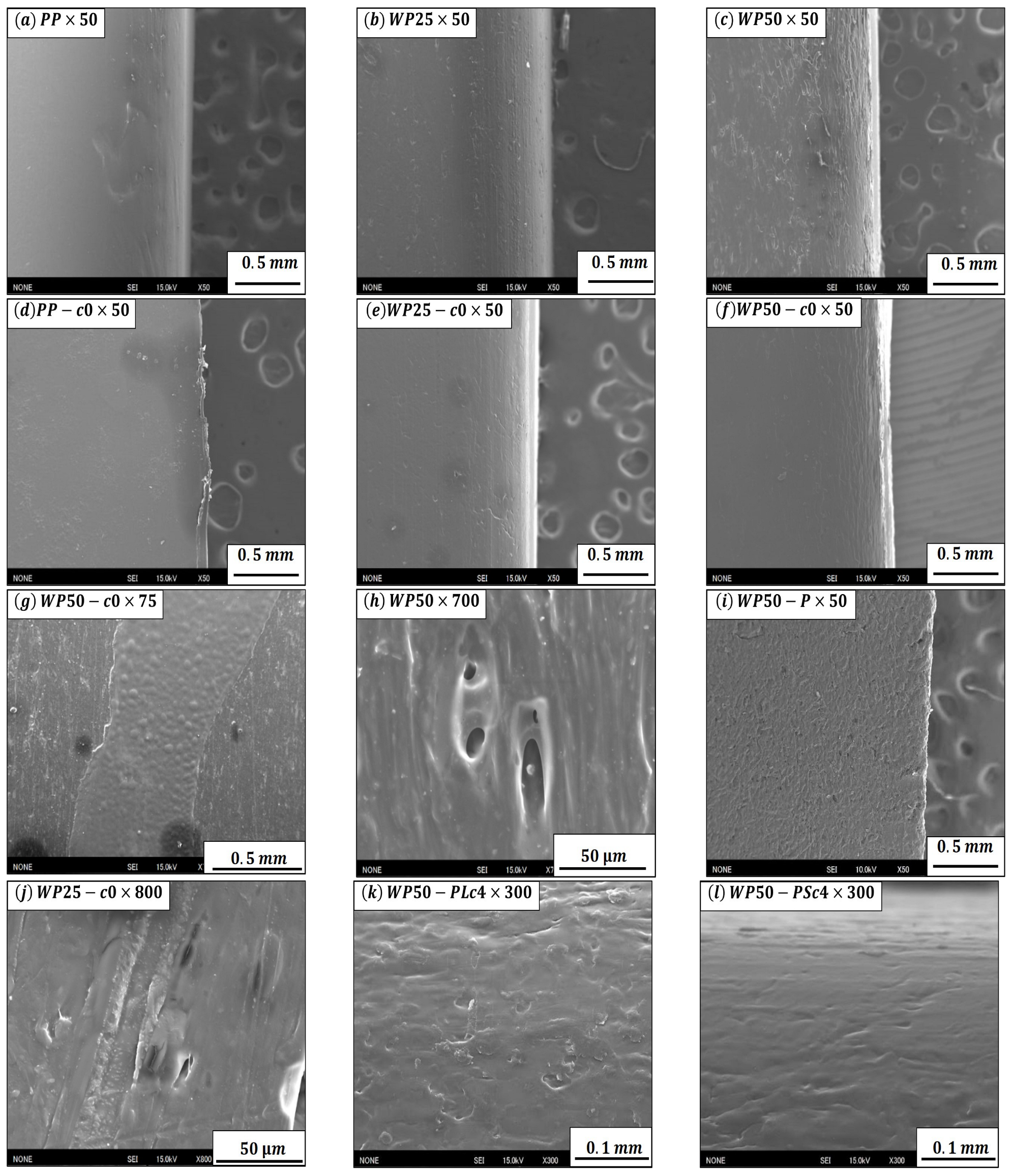
3.1. S E M Surface Observation Results

Representative SEM images are displayed in Figure 3. From the micrographs, it’s evident that the surface of as-received neat PP specimen appears smoother than the reinforced composites. However, after introducing WF into the PP matrix, the surface became commensurately rough. In fact, as the WF content was increased from 25 wt% (Figure 3b) to 50 wt% (Figure 3c), surface roughness correspondingly increased, and more voids and irregularities were observed. In addition, by comparing Figure 3c with Figure 3f, it can be seen, as is the case with the other corresponding micrographs, that the acryl resin-coated specimens had relatively smoother surfaces than the non-coated specimens. This is because the coating improved homogeneity of the specimen surface by filling up the voids, thus covering the interface where wood fibers would otherwise have been exposed.
In the case of WP50-c0 specimen (see Figure 3g), the surfaces to which the film adheres or does not are clearly distinguishable, attesting to the hydrophobic nature of PP. It is worth noting that when the plasma treated specimens were examined before applying the resin coating (see Figure 3i), their surfaces appeared bumpier than the surfaces of non-plasma treated specimens. This can be ascribed to the property of plasma to modify the PP on the specimen surface in order to improve adhesion of the resin coating. Yáñez-Pacios et al. [38] achieved similar results by applying UV/ozone treatment on WPCs. Wolkenhauer et al. [39] also detected an increase in surface roughness of WPCs after plasma treatment and considered it a depiction of enhanced bond strength. They further conducted tensile and shear bond strength tests and ascertained that solvent-borne, waterborne, and oil-based paints adhered more to the surfaces of plasma treated WPC/PP specimens than to the surfaces of as-received specimens.
Morphological changes also ensued after applying the acrylic paint. At higher magnification, the surface of as-received WP50 composite looks heterogeneous (see Figure 3h), and voids are clearly visible. However, looking at the surface topography of WP50 specimen coated with acrylic resin (Figure 3j), it’s evident that the coating resin covered the voids, hence preventing irregularities and scratches which occurred on the surface of the test piece during fabrication, resulting into a relatively homogeneous surface.
The effect of CNF-L and CNF-S on surface roughness are clearly distinguished by the images in Figure 3k,l, as the former appears more irregular than the latter. Thus, it may be deduced that short CNF coating is more effective in achieving a smooth surface in comparison to long CNF.

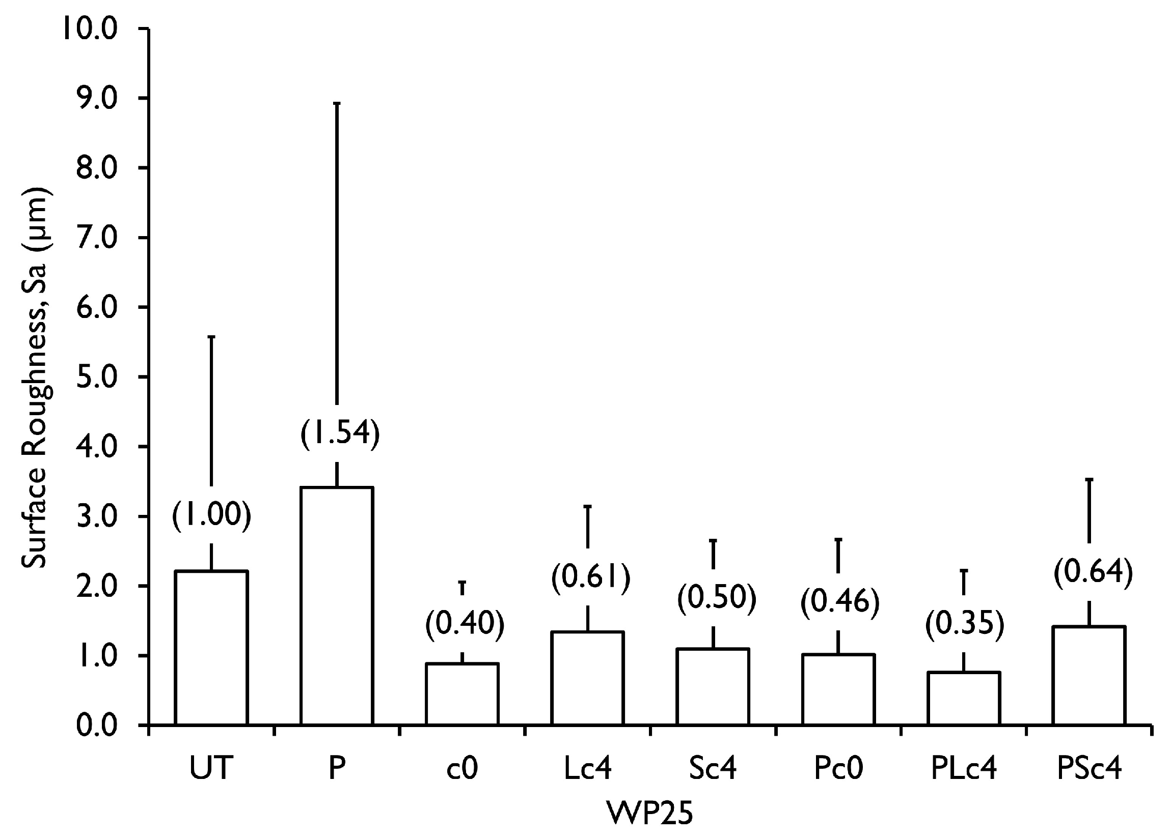
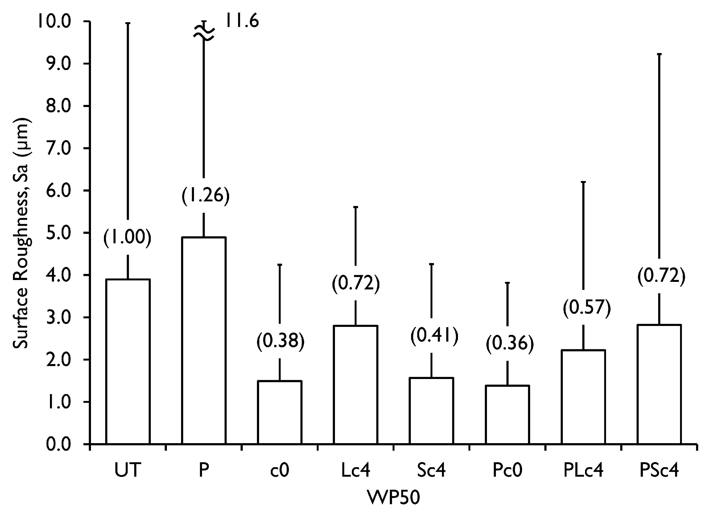
3.2. Surface Roughness Measurement Results

Surface roughness ( S a ) measurement results of neat PP, WP25, and WP50 specimens obtained from the color laser microscope are reported in Figure 4, Figure 5 and Figure 6. In each specimen category, the changes in S a of the treated specimens relative to the untreated specimens are expressed as ratios and shown in parentheses, whilst the respective root mean square ( S q ) values are represented by the error bars. As can be seen with the case of neat PP and WP25 specimen categories shown in Figure 4 and Figure 5, their S q values were higher before surface coating than after surface coating. This was also the case with the WP50 specimens (see Figure 6), except for the PSc4 specimen which showed a unique increase in S q value after surface coating. Thus, it was confirmed that in nearly all the cases, surface coating had an effect of decreasing the S q values. It is also manifest in Figure 4 that neat PP had an S a value of 1.40 µm before coating, but it reduced to an average of 0.79 µm after coating. Similarly, there was a reduction in S a of WP25 from 2.20 µm before coating to an average value of 1.09 µm after coating as shown in Figure 5. The same trend was also observed with the WP50 specimens (see Figure 6), which showed an decrease in surface roughness from 3.90 µm before coating to a mean value of 2.05 µm after coating. In other words, surface roughness values were approximately halved in all the samples after coating. Furthermore, prior to the resin coating, the values of S a were relatively higher in all the plasma treated PP, WP25, and WP50 specimens before coating, implying that plasma irradiation increased the surface roughness of the specimens as was observed in the SEM micro-graphs.
This significant alteration of surface topography had also been reported by previous researchers. Hünnekens et al. [40], who investigated the effect of atmospheric pressure plasma treatment on WPC surface morphology and chemistry, posited that an extension of exposure time from 10 s to 60 s causes remarkable degradation and exposes the wood particles. Consequently, adhesion and wettability of the hydrophobic matrix is not enhanced, and the original purpose of surface modification is defeated due to hydrophobic recovery, as reported by Mortazavi et al., and Bormashenko et al. [41,42]. Therefore, an empirical determination of the optimum exposure time is crucial for achieving best results. Based on the above results, it was generally deduced that acrylic resin coating is useful for the reduction of surface roughness of specimens, regardless of the application of plasma treatment.

3.3. Tensile Test Results

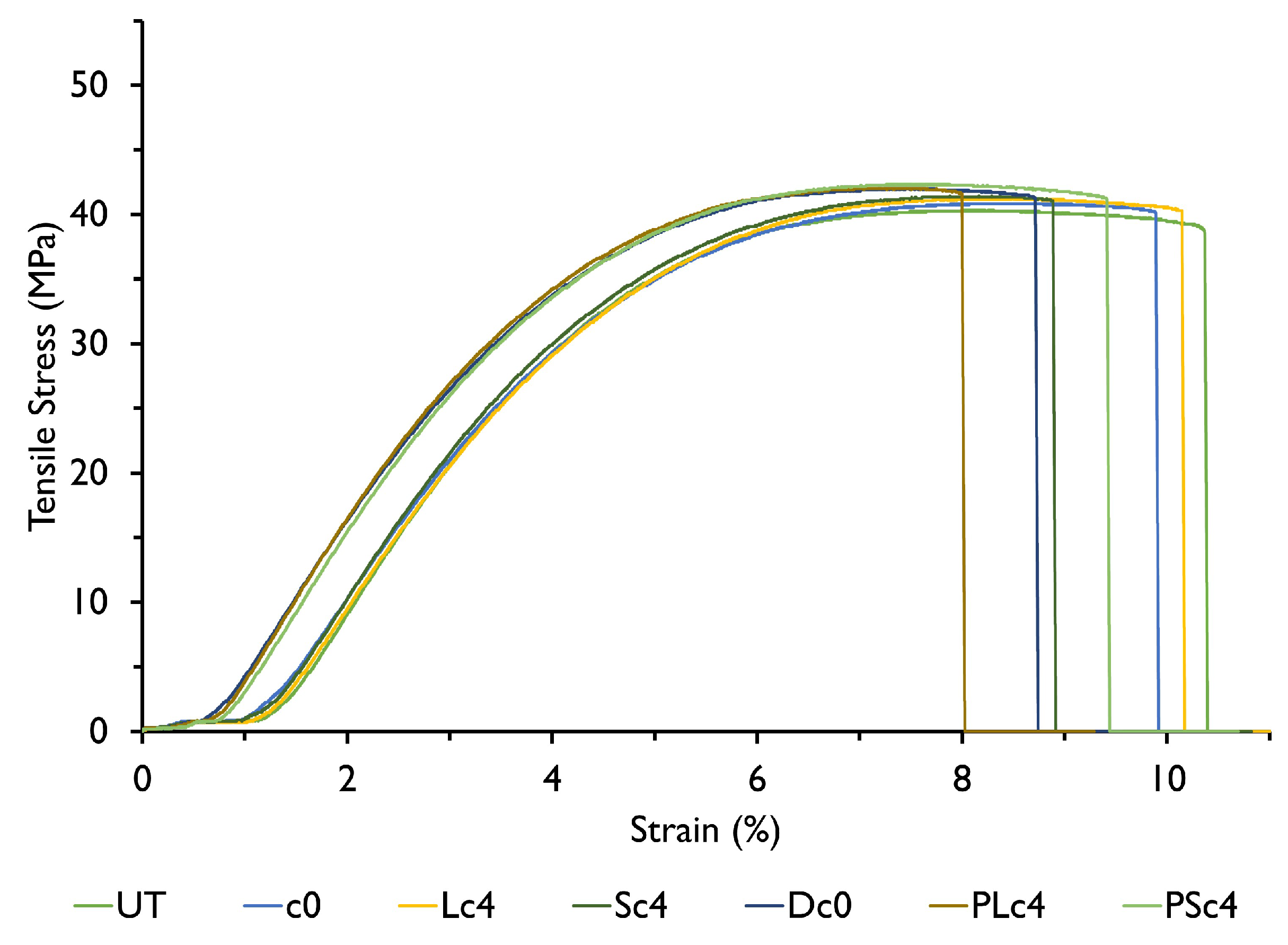
3.3.1. Tensile Test Results of Neat PP

The effect of acrylic resin, CNF coating, and plasma treatment on tensile strength of PP is illustrated in Figure 7, and a typical stress-strain plot is shown in Figure 8. From the results, it is readily apparent that for two categories of neat PP specimens, i.e., the untreated specimens (UT), and the resin coated specimens without CNF (c0), considerable plastic deformation was observed through the entire test duration fol-lowed by necking, but no fracture occurred (See Figure 7). In both specimen categories, the percentage elongation was more that 300% of the original gauge length after tensile test. This confirms the ductility of neat PP. It is obvious that the extensive plasticity of PP delayed crack propagation due to its tendency to absorb large amounts of energy prior to fracture.
Contrariwise, fracture occurred on the CNF coated PP specimens, which also recorded lower elongation at break. It is worth mentioning that a further decrease in fracture strain was witnessed when plasma treatment was performed. This is because the introduction of CNF coating film on the surface of neat PP induced brittleness to the specimen surface, hence the transition from ductile to brittle failure. The observed decrease in fracture strain is also attributed to the brittleness of the coating film itself, which must have ruptured before the specimen, hence propagating the cracks to the test piece. This eventually caused localized stress concentrations at the surface area in contact with the fractured film coating, occasioning early fracture of the coated specimen. The plasma-treated test-pieces had the largest decrease in fracture strain com-pared to the non-plasma treated specimens because the coating adheres more to the plasma-treated surface than to the non-treated surface. Consequently, crack propagation occurred faster leading to premature fracture. Conversely, adhesion of the coating to the non-plasma treated test-piece was relatively weaker than those treated with plasma, making fracture propagation difficult. As a result, the least decrease in fracture strain was witnessed. Furthermore, the property of PP to undergo appreciable deformation before fracture may have also been exhibited.
Furthermore, it is discernible that the coating agent increased the tensile strength of the non-plasma treated and plasma treated specimens by 2.0–2.3% and 5.4–7.1%, respectively. This increase in tensile strength can be attributed to the formation of an acrylic film coating which covered the scratches and irregularities on the specimen surface, thereby making it homogeneous. As such, the unevenness of the specimen surface was suppressed by the coating, which is considered to delay the shift to non-linear deformation, as can be seen in Figure 8. This finding attests to the effectiveness of plasma treatment in improving tensile strength of materials. Moreover, the fact that such an increase in strength was obtained simply by immersing the plasma-treated specimen in acrylic paint is considered to be an extremely important finding from the viewpoint of material quality control.

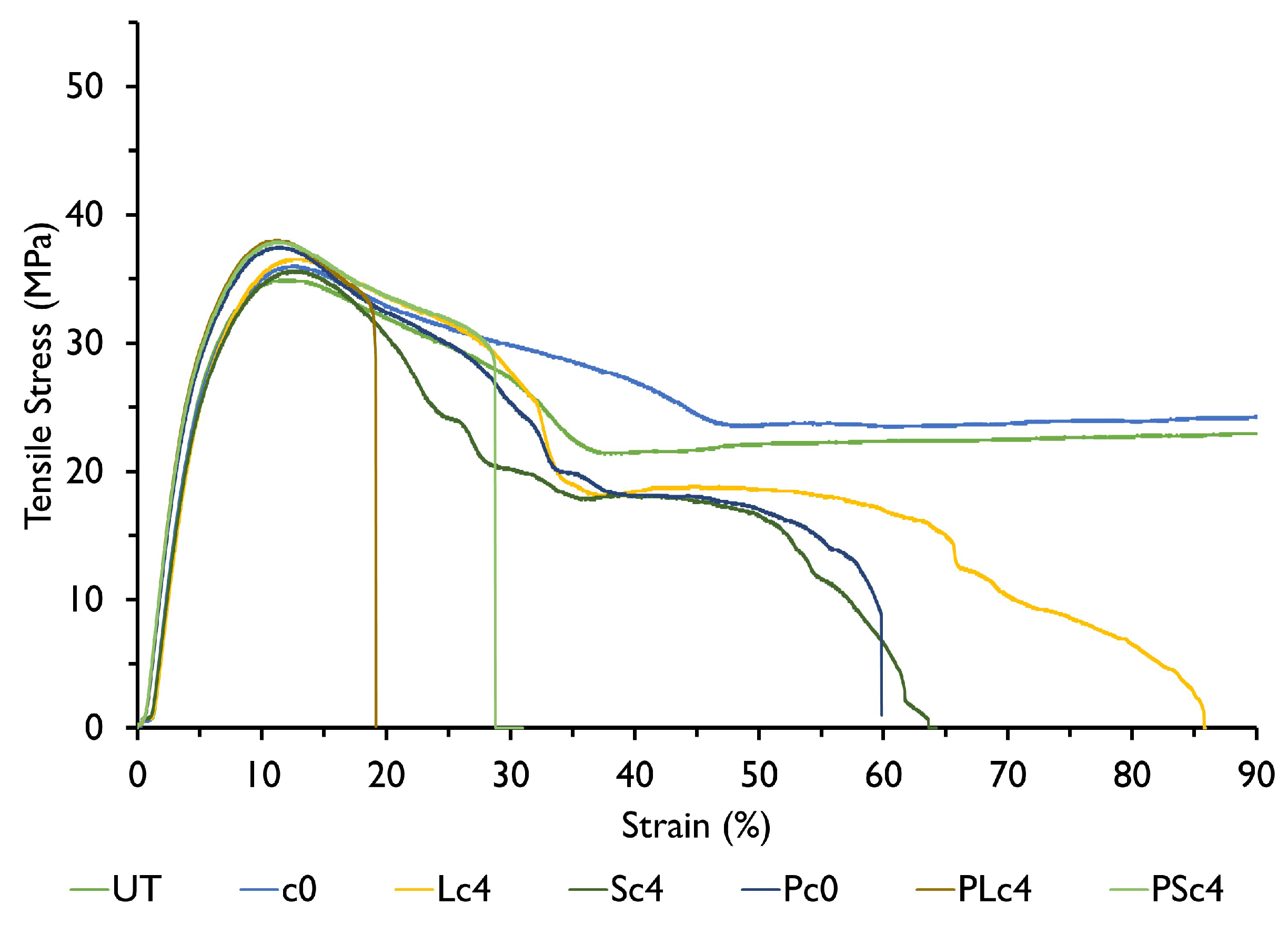
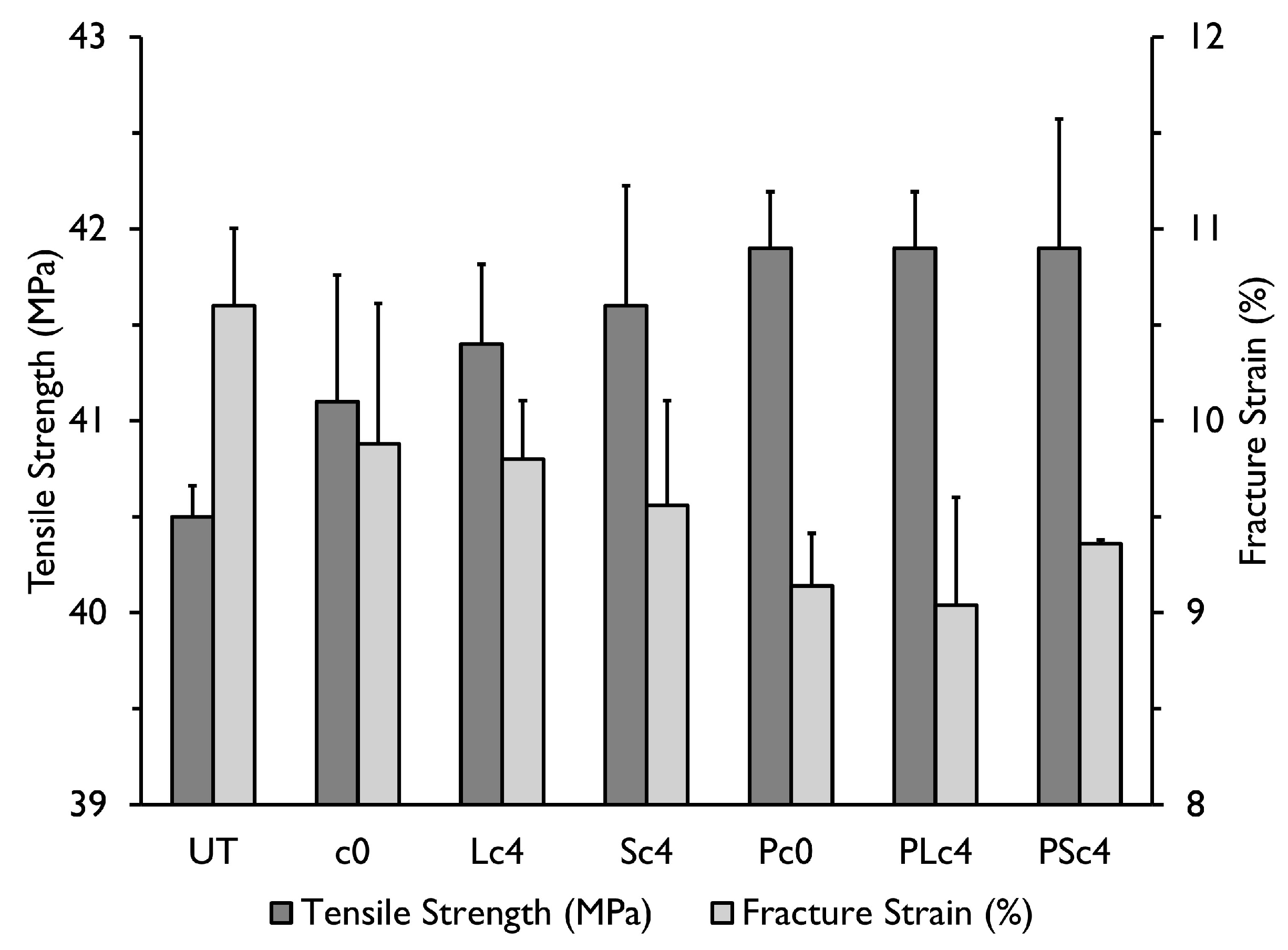
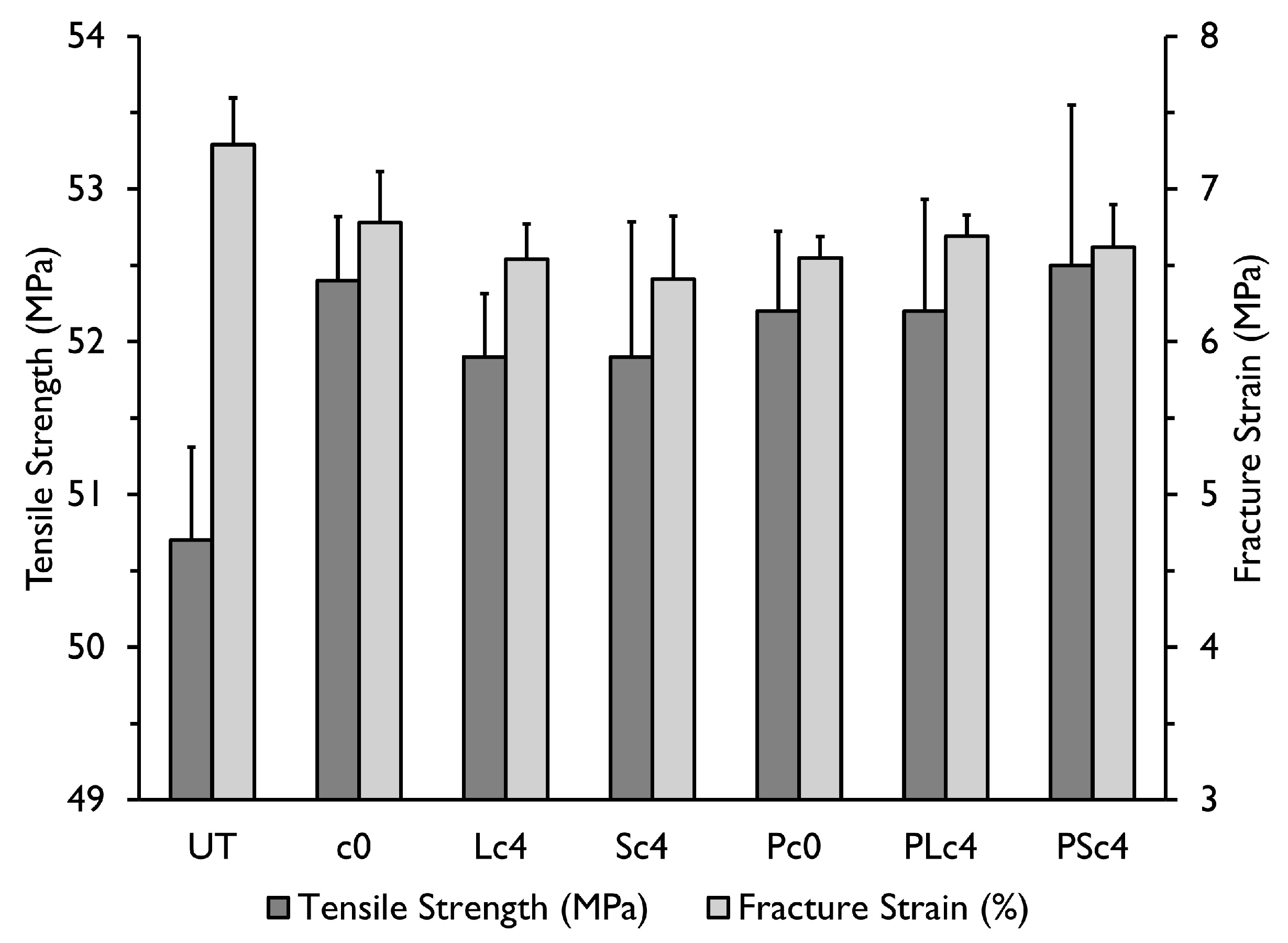
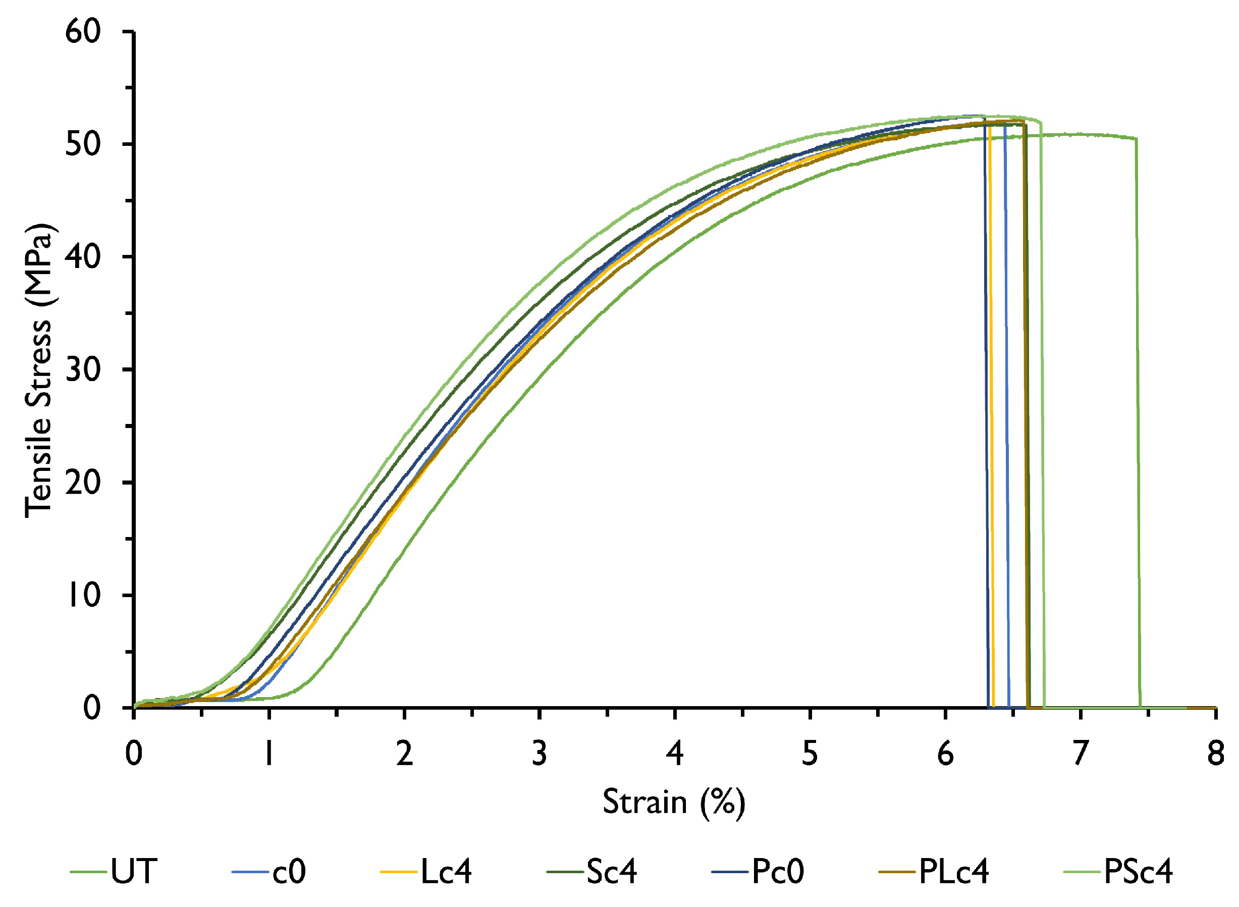
3.3.2. Tensile Test Results of WP25 and WP50 Specimens

The effect of acrylic resin, CNF coating, and plasma treatment on tensile strength of WP25 and WP50 specimens are reported in Figure 9 and Figure 10. The corresponding stress-strain plots are also illustrated in Figure 11 and Figure 12. From the results of WP25 and WP50 specimens, it can be observed that tensile strengths of the specimens increased when the coating agent was applied. The non-plasma treated WP25 composites manifested a strength increase of 1.5–2.7%, whereas the plasma-treated WP25 composites exhibited an increase of 3.5–3.7%. As for the WP50 composites, tensile strength increased by 2.4–3.5% and 3.0–3.6% for the non-plasma and plasma treated specimens, respectively. The observed increase in strength was attributed to the coating film which covered the voids formed on the untreated WP25 and WP50 specimen surfaces as a result of the incorporation of WF into the PP matrix. Prior to coating, the voids and scratches were considered responsible for crack initiation and propagation, resulting into brittle fracture of the non-coated specimens. However, applying acrylic coating resin on the specimen surface filled up the voids, subsequently boosting the material’s resistance to crack. Additionally, the coating film improved surface roughness and homogeneity of the composites causing the stresses to be evenly distributed throughout the test pieces, and preventing localized stress concentration on the specimen’s surface. Accordingly, by these two aspects: blocking and strengthening the fracture origin as well as increased homogeneity, tensile strength of the specimens was enhanced. Thus, based on the results in Figure 9 and Figure 10, it can be deduced that the initial blocking and strengthening effects were more responsible for the increase in tensile strength.
This tendency of a material’s strength to improve after plasma treatment was also reported by Demirkir et al. [43], who investigated the effect of oxygen plasma surface treatment on the elastic modulus and bending strength of beech and plywood. In contrast with the non-treated samples, they reported an increase in bending strength of all plywood panels after oxygen plasma treatment. Wolkenhauer et al. [44] also observed an improvement in adhesion behavior of some wood species after plasma treatment. Seki et al. [45] similarly noticed an increase in inter-facial adhesion of jute fiber reinforced polyethylene composites after plasma treatment.
On the other hand, fracture strain decreased after applying the acrylic coating as was reported in the case of neat PP, and it decreased even further after plasma treatment. This decrease is attributed to improved adhesion of the coating to the specimen surface by plasma treatment, causing rapid crack propagation from the coating film to the specimen body as was explained earlier. By comparing the results of both plasma-treated PP and WP test-pieces, it is discernible that tensile strength improvement rate was higher in neat PP than in the reinforced composites, i.e., 5.4–7.1%, and a mean value of 3.5% in neat PP and WP composites, respectively. Moreover, as the proportion of PP matrix in the composite decreased, the effect of plasma treatment correspondingly diminished. For this reason, the plasma-treated WP50 composites recorded marginal differences in tensile strength from the non-plasma-treated, resin coated WP50 composites.

3.4. Effect of Coating Film Thickness on Tensile Strength

It was of particular interest to establish whether the coating film thickness also had an influence on tensile strength of the composites. Therefore, coating film stress at maximum specimen stress, denoted by σ f , for each specimen was computed based on the following rule of mixtures by assuming uniform coating thickness:
σ c A c = σ n c A n c + σ f A f
where σ n c and σ c stand for tensile strength of the non-coated and coated specimen, respectively, whereas A n c , and A c refer to the specimen cross-sectional area before and after coating, in that order, and A f is the film cross-sectional area. The results are shown in Table 2, with the σ f values rounded off to the nearest whole number. It can be seen that there were large variations of σ f across all the categories of neat PP, WP25, and WP50 specimens. Additionally, there was no significant distinction, or trend in the magnitude of σ f for specimens with, or without CNF coating. Furthermore, the minimum value of σ f obtained was higher than 144 MPa, i.e., the computed film stress at maximum specimen stress was much greater than the actual tensile strength of acrylic resin, which is impractical. Therefore, it was concluded that coating film stress was not responsible for the observed increase in tensile strength of the specimens. Rather, this increase was solely attributed to homogenization of the specimen surface by the coating resin, which covered the voids and improved surface roughness, as explained before. As such, further research would still be necessary to detail the relationship between film coating thickness and tensile strength of WPCs, and to investigate the quantitative range of coating thicknesses in which the present results can be achieved.

3.5. Comparison of Tensile Strength Variation with the Type of CNF Coating

From the tensile strength results of 4 % CNF-S and 4 % CNF-L, it’s clear that there was no significant difference in tensile strength based on the type of CNF used, i.e., long or short. However, by comparing tensile strengths of all the 4% CNF coated specimens against those coated with acrylic paint alone, i.e., 0% CNF, it is evident that the 4% CNF coated specimens generally yielded higher tensile strengths than those with 0% CNF, the WP50 non-plasma treated specimen being the only exception. Table 3 and Table 4 show this comparison for both non-plasma treated and plasma treated specimens. In each case, the tensile strength of 4% CNF was obtained by calculating average tensile strengths of the 4% CNF-S and 4% CNF-L specimens corresponding to each fiber weight fraction category. Nevertheless, this increase in tensile strength as a result of incorporating CNF into the acrylic paint is seen to be minimal, as per the results of this study. Therefore, further research on CNF coating is still necessary to achieve greater enhancement of tensile strength.

4. Conclusions

In this study, short fiber reinforced composite materials were developed using PP matrix and WF reinforcement at various fiber-matrix ratios. An acrylic coating resin was then applied on the surface of the fabricated specimens, and CNF was incorporated to investigate the effect of CNF-S and CNF-L on the surface roughness and tensile properties of the composites. Additionally, the effect of plasma irradiation on the mechanical characteristics of the composites was investigated. SEM results showed that the addition of WF into the PP matrix resulted in the formation of voids which increased the specimen surface roughness. However, applying acrylic paint on the specimen surface tended to cover the voids, subsequently reducing the surface roughness by ∼50%. Moreover, scanning electron micro-graphs revealed that the surfaces of specimens coated with CNF-S looked smoother in comparison to those of specimens coated with CNF-L. This corroborates the effect of CNF type on specimen surface texture. It was also deduced that both surface coating and plasma treatment increased the tensile strength of PP and WP specimens. However, the effect of CNF coating on tensile strength was minimal. In addition, fracture strength was not influenced by the thickness of the coating film. Therefore, further investigation should be done to ascertain the effects of CNF-S, CNF-L and coating thickness on the tensile strength of WPCs. Fracture strain decreased after the coating agent was applied. Greater decrease in fracture strain was manifest in the plasma-treated specimens, attesting to the occurrence of early fracture in the plasma-treated specimens due to induced brittleness by the coating film. Ultimately, besides enhancing the surface finish of composites and plastics, it was deduced that surface coating could be an effective means of improving the tensile strength of WPCs.

Author Contributions

Conceptualization, W.O. and K.G.; methodology, W.O. and M.K.; validation, W.O. and M.K.; resources, W.O., M.A., A.M. and K.G.; data curation, W.O. and M.K.; writing—original draft preparation, W.O.; writing—review and editing, W.O. and K.G.; visualization, W.O., M.K. and K.G.; supervision, K.G. and A.M.; project administration, W.O. and K.G.; funding acquisition, W.O. and K.G. All authors have read and agreed to the published version of the manuscript.

Funding

This research was funded by the Government of Japan through the Ministry of Education, Culture, Sports, Science and Technology (MEXT).

Data Availability Statement

The data that support the findings of this study are available from the corresponding author upon request.

Acknowledgments

The authors of this work would like to thank the Ministry of Education, Culture, Sports, Science and Technology (MEXT) of the Government of Japan for funding this research. Special thanks also go to Hisanori Miyoshi of Nihon Plasmatreat, Inc., for his helpful guidance on plasma irradiation.

Conflicts of Interest

The authors declare no conflict of interest. The funders had no role in the design of the study; in the collection, analyses, or interpretation of data; in the writing of the manuscript; or in the decision to publish the results.

Abbreviations

The following abbreviations are used in this manuscript:
CFRPsCarbon Fiber Reinforced Plastics
GFRPsGlass Fiber Reinforced Plastics
FRPsFiber Reinforced Plastics
SEM   Scanning Electron Microscope
WPCsWood Plastic Composites
CNFCellulose Nanofiber
MAPPMaleic Anhydride Grafted Polypropylene
WFWood Flour
WPWood-Polypropylene Composite
MAMaleic Anhydride
PETPolyethylene Terephthalate
PEPolyethylene
PPPolypropylene

References

  1. Ondiek, W.O.; Ngetha, H.; Keraita, J.N.; Byiringiro, J.B. Investigating the effect of fiber concentration and fiber size on mechanical properties of rice husk fiber reinforced polyester composites. Int. J. Compos. Mater. 2018, 8, 105–115. [Google Scholar]
  2. Rangappa, S.M.; Siengchin, S.; Parameswaranpillai, J.; Jawaid, M.; Ozbakkaloglu, T. Lignocellulosic fiber reinforced composites: Progress, performance, properties, applications, and future perspectives. Polym. Compos. 2022, 43, 645–691. [Google Scholar] [CrossRef]
  3. Prashanth, S.; Subbaya, K.; Nithin, K.; Sachhidananda, S. Fiber reinforced composites-a review. J. Mater. Sci. Eng. 2017, 6, 2–6. [Google Scholar]
  4. Elanchezhian, C.; Ramnath, B.V.; Ramakrishnan, G.; Rajendrakumar, M.; Naveenkumar, V.; Saravanakumar, M. Review on mechanical properties of natural fiber composites. Mater. Today Proc. 2018, 5, 1785–1790. [Google Scholar] [CrossRef]
  5. Asyraf, M.; Rafidah, M.; Azrina, A.; Razman, M. Dynamic mechanical behaviour of kenaf cellulosic fibre biocomposites: A comprehensive review on chemical treatments. Cellulose 2021, 28, 2675–2695. [Google Scholar] [CrossRef]
  6. Xu, B.; Wei, M.Y.; Wu, X.Y.; Lei, J.G.; Zhou, Z.W.; Fu, L.Y.; Zhu, L.K. An Injecting Molding Method for Forming the HFRP/PA6 Composite Parts. Polymers 2022, 14, 5085. [Google Scholar] [CrossRef]
  7. Sayam, A.; Rahman, A.M.; Rahman, M.S.; Smriti, S.A.; Ahmed, F.; Rabbi, M.F.; Hossain, M.; Faruque, M.O. A review on carbon fiber-reinforced hierarchical composites: Mechanical performance, manufacturing process, structural applications and allied challenges. Carbon Lett. 2022, 32, 1173–1205. [Google Scholar] [CrossRef]
  8. Andrzejewski, J.; Barczewski, M.; Szostak, M. Injection molding of highly filled polypropylene-based biocomposites. Buckwheat husk and wood flour filler: A comparison of agricultural and wood industry waste utilization. Polymers 2019, 11, 1881. [Google Scholar] [CrossRef] [Green Version]
  9. Haque, M.M.U.; Goda, K.; Ogoe, S.; Sunaga, Y. Fatigue analysis and fatigue reliability of polypropylene/wood flour composites. Adv. Ind. Eng. Polym. Res. 2019, 2, 136–142. [Google Scholar] [CrossRef]
  10. Dauletbek, A.; Li, H.; Xiong, Z.; Lorenzo, R. A review of mechanical behavior of structural laminated bamboo lumber. Sustain. Struct. 2021, 1, 000004. [Google Scholar] [CrossRef]
  11. Ashik, K.; Sharma, R.S. A review on mechanical properties of natural fiber reinforced hybrid polymer composites. J. Miner. Mater. Charact. Eng. 2015, 3, 420. [Google Scholar] [CrossRef]
  12. Jariwala, H.; Jain, P. A review on mechanical behavior of natural fiber reinforced polymer composites and its applications. J. Reinf. Plast. Compos. 2019, 38, 441–453. [Google Scholar] [CrossRef]
  13. Hua, L.S.; Chen, L.W.; Geng, B.J.; Kristak, L.; Antov, P.; Pędzik, M.; Rogoziński, T.; Taghiyari, H.R.; Lubis, M.A.R.; Fatriasari, W.; et al. Particleboard from agricultural biomass and recycled wood waste: A review. J. Mater. Res. Technol. 2022, 20, 4630–4658. [Google Scholar]
  14. Jian, B.; Mohrmann, S.; Li, H.; Li, Y.; Ashraf, M.; Zhou, J.; Zheng, X. A Review on Flexural Properties of Wood-Plastic Composites. Polymers 2022, 14, 3942. [Google Scholar] [CrossRef]
  15. Lamba, P.; Kaur, D.P.; Raj, S.; Sorout, J. Recycling/reuse of plastic waste as construction material for sustainable development: A review. Environ. Sci. Pollut. Res. 2022, 29, 86156–86179. [Google Scholar] [CrossRef]
  16. Nordin, M.; Makino, Y.; Goda, K.; Ito, H. Fatigue fracture properties of wood plastic composites. Sen-Gakkaishi 2015, 71, 339–344. [Google Scholar]
  17. Pokhrel, G.; Gardner, D.J.; Han, Y. Properties of wood–plastic composites manufactured from two different wood feedstocks: Wood flour and wood pellets. Polymers 2021, 13, 2769. [Google Scholar] [CrossRef]
  18. Friedrich, D. Change in key mechanical properties from postprocess hot pressing of commercial wood-plastic composites with different fibre contents. Polym. Bull. 2023, 80, 4263–4288. [Google Scholar] [CrossRef]
  19. Friedrich, D. Additive manufacturing of post-process thermoformed wood-plastic composite cladding. Autom. Constr. 2022, 139, 104322. [Google Scholar] [CrossRef]
  20. Carter, N.; Grant, I.; Dewey, M.; Bourque, M.; Neivandt, D.J. Production and Characterization of Cellulose Nanofiber Slurries and Sheets for Biomedical Applications. Front. Nanotechnol. 2021, 3, 86. [Google Scholar] [CrossRef]
  21. Wang, L.; Okada, K.; Hikima, Y.; Ohshima, M.; Sekiguchi, T.; Yano, H. Effect of cellulose nanofiber (CNF) surface treatment on cellular structures and mechanical properties of polypropylene/CNF nanocomposite foams via core-back foam injection molding. Polymers 2019, 11, 249. [Google Scholar] [CrossRef] [PubMed] [Green Version]
  22. Jung, B.N.; Jung, H.W.; Kang, D.; Kim, G.H.; Shim, J.K. Synergistic effect of cellulose nanofiber and nanoclay as distributed phase in a polypropylene based nanocomposite system. Polymers 2020, 12, 2399. [Google Scholar] [CrossRef]
  23. Sharma, A.; Thakur, M.; Bhattacharya, M.; Mandal, T.; Goswami, S. Commercial application of cellulose nano-composites—A review. Biotechnol. Rep. 2019, 21, e00316. [Google Scholar] [CrossRef] [PubMed]
  24. Nelson, K.; Retsina, T.; Iakovlev, M.; van Heiningen, A.; Deng, Y.; Shatkin, J.A.; Mulyadi, A. American process: Production of low cost nanocellulose for renewable, advanced materials applications. In Materials Research for Manufacturing: An Industrial Perspective of Turning Materials into New Products; Springer: Berlin/Heidelberg, Germany, 2016; pp. 267–302. [Google Scholar]
  25. Wu, B.; Wang, S.; Tang, J.; Lin, N. Nanocellulose in high-value applications for reported trial and commercial products. In Advanced Functional Materials from Nanopolysaccharides; Springer: Berlin/Heidelberg, Germany, 2019; pp. 389–409. [Google Scholar]
  26. Behera, A.; Behera, A. Nanomaterials. In Advanced Materials: An Introduction to Modern Materials Science; Springer: Berlin/Heidelberg, Germany, 2022; pp. 77–125. [Google Scholar]
  27. Eichhorn, S.; Baillie, C.; Zafeiropoulos, N.; Mwaikambo, L.; Ansell, M.; Dufresne, A.A.; Entwistle, K.; Herrera-Franco, P.; Escamilla, G.; Groom, L.; et al. Current international research into cellulosic fibres and composites. J. Mater. Sci. 2001, 36, 2107–2131. [Google Scholar] [CrossRef]
  28. Vidales-Herrera, J.; López, I. Nanomaterials in coatings: An industrial point of view. In Handbook of Nanomaterials for Manufacturing Applications; Elsevier: Amsterdam, The Netherlands, 2020; pp. 51–77. [Google Scholar]
  29. Hämäläinen, K.; Kärki, T. Effects of atmospheric plasma treatment on the surface properties of wood-plastic composites. In Proceedings of the Advanced Materials Research. Trans. Tech. Publ. 2013, 718, 176–185. [Google Scholar]
  30. Yáñez-Pacios, A.J.; Martín-Martínez, J.M. Comparative adhesion, ageing resistance, and surface properties of wood plastic composite treated with low pressure plasma and atmospheric pressure plasma jet. Polymers 2018, 10, 643. [Google Scholar] [CrossRef] [Green Version]
  31. Yuji, N. Surface modification technology: Current situation and future development. Appl. Phys. 2013, 82, 376–384. [Google Scholar]
  32. Friedrich, J.; Wigant, L.; Unger, W.; Lippitz, A.; Wittrich, H. Corona, spark and combined UV and ozone modification of polymer films WeBP23. Surf. Coat. Technol. 1998, 98, 879–885. [Google Scholar] [CrossRef]
  33. Yáñez-Pacios, A.J.; Martín-Martínez, J.M. Surface modification and improved adhesion of wood-plastic composites (WPCs) made with different polymers by treatment with atmospheric pressure rotating plasma jet. Int. J. Adhes. Adhes. 2017, 77, 204–213. [Google Scholar] [CrossRef]
  34. Scarselli, G.; Quan, D.; Murphy, N.; Deegan, B.; Dowling, D.; Ivankovic, A. Adhesion improvement of thermoplastics-based composites by atmospheric plasma and UV treatments. Appl. Compos. Mater. 2021, 28, 71–89. [Google Scholar] [CrossRef]
  35. Nordin, M.; Sakamoto, K.; Azhari, H.; Goda, K.; Okamoto, M.; Ito, H.; Endo, T. Tensile and impact properties of pulverized oil palm fiber reinforced polypropylene composites: A comparison study with wood fiber reinforced polypropylene composites. J. Mech. Eng. Sci. 2018, 12, 4191–4202. [Google Scholar] [CrossRef]
  36. Isogai, A. Structural characterization and modifications of surface-oxidized cellulose nanofiber. J. Jpn. Pet. Inst. 2015, 58, 365–375. [Google Scholar] [CrossRef] [Green Version]
  37. Fujisawa, S.; Saito, T.; Kimura, S.; Iwata, T.; Isogai, A. Surface engineering of ultrafine cellulose nanofibrils toward polymer nanocomposite materials. Biomacromolecules 2013, 14, 1541–1546. [Google Scholar] [CrossRef]
  38. Yáñez-Pacios, A.J.; Martín-Martínez, J.M. Surface modification and adhesion of wood-plastic composite (WPC) treated with UV/ozone. Compos. Interfaces 2018, 25, 127–149. [Google Scholar] [CrossRef]
  39. Wolkenhauer, A.; Avramidis, G.; Hauswald, E.; Militz, H.; Viöl, W. Plasma treatment of wood–plastic composites to enhance their adhesion properties. J. Adhes. Sci. Technol. 2008, 22, 2025–2037. [Google Scholar] [CrossRef]
  40. Hünnekens, B.; Avramidis, G.; Ohms, G.; Krause, A.; Viöl, W.; Militz, H. Impact of plasma treatment under atmospheric pressure on surface chemistry and surface morphology of extruded and injection-molded wood-polymer composites (WPC). Appl. Surf. Sci. 2018, 441, 564–574. [Google Scholar] [CrossRef]
  41. Mortazavi, M.; Nosonovsky, M. A model for diffusion-driven hydrophobic recovery in plasma treated polymers. Appl. Surf. Sci. 2012, 258, 6876–6883. [Google Scholar] [CrossRef]
  42. Bormashenko, E.; Chaniel, G.; Grynyov, R. Towards understanding hydrophobic recovery of plasma treated polymers: Storing in high polarity liquids suppresses hydrophobic recovery. Appl. Surf. Sci. 2013, 273, 549–553. [Google Scholar] [CrossRef]
  43. Demirkir, C.; Aydin, I.; Colak, S.; Ozturk, H. Effects of plasma surface treatment on bending strength and modulus of elasticity of beech and poplar plywood. Maderas. Cienc. Tecnol. 2017, 19, 195–202. [Google Scholar] [CrossRef] [Green Version]
  44. Wolkenhauer, A.; Avramidis, G.; Hauswald, E.; Militz, H.; Viöl, W. Sanding vs. plasma treatment of aged wood: A comparison with respect to surface energy. Int. J. Adhes. Adhes. 2009, 29, 18–22. [Google Scholar] [CrossRef]
  45. Seki, Y.; Sever, K.; Sarikanat, M.; Güleç, H.A.; Tavman, I.H. The influence of oxygen plasma treatment of jute fibers on mechanical properties of jute fiber reinforced thermoplastic composites. In Proceedings of the 5th International Advanced Technologies Symposium (IATS’09), Karabuk, Turkey, 13–15 May 2009; Volume 13. [Google Scholar]
Figure 1. Raw materials: (a) Polypropylene (PP), J-108M (Prime Polymer Co., Ltd.) (b) WF/PP masterbatch, Celbrid-N (Toclas Co., Ltd.). (c) MAPP compatibilizer (Kayaku Akzo Co., Ltd.).
Jcs 07 00296 g001
Figure 2. 2D CAD model of JIS K7139-A32 tensile test specimen (all dimensions are in mm).
Jcs 07 00296 g002
Figure 3. Representative SEM surface micrographs of PP, WP25 and WP50 specimens.
Jcs 07 00296 g003
Figure 4. Surface roughness results for neat PP specimens. Changes in S a of the treated specimens relative to the untreated specimens are expressed as ratios and shown in parentheses, whilst the respective root mean square (Sq) values are represented by the error bars.
Jcs 07 00296 g004
Figure 5. Surface roughness results for WP25 specimens.Changes in S a of the treated specimens relative to the untreated specimens are expressed as ratios and shown in parentheses, whilst the respective root mean square (Sq) values are represented by the error bars.
Jcs 07 00296 g005
Figure 6. Surface roughness results for WP50 specimens. Changes in S a of the treated specimens relative to the untreated specimens are expressed as ratios and shown in parentheses, whilst the respective root mean square (Sq) values are represented by the error bars.
Jcs 07 00296 g006
Figure 7. Effect of CNF coating and plasma treatment on tensile strength and fracture strain of neat PP specimens. Each error bar shows the standard deviation.
Jcs 07 00296 g007
Figure 8. Tensile stress-strain curves for neat PP specimens.
Jcs 07 00296 g008
Figure 9. Effect of CNF coating and plasma treatment on tensile strength and fracture strain of WP25 specimens. Each error bar shows the standard deviation.
Jcs 07 00296 g009
Figure 10. Effect of CNF coating and plasma treatment on tensile strength and fracture strain of WP50 specimens. Each error bar shows the standard deviation.
Jcs 07 00296 g010
Figure 11. Tensile stress-strain curves for WP25 specimens.
Jcs 07 00296 g011
Figure 12. Tensile stress-strain curves for WP50 specimens.
Jcs 07 00296 g012
Table 1. Percentage proportions of masterbatch constituents [16].
WFPPMAPP
68.1 wt%29.2 wt%2.7 wt%
Table 2. Coating film stress values at maximum tensile stress of PP, WP25 and WP50 specimens.
Specimen TypeType of Treatment σ f (MPa)
Neat PPc0155
Lc4144
Sc4163
Pc0286
PLc4308
PSc4218
WP25c0206
Lc4173
Sc4394
Pc0290
PLc4185
PSc4207
WP50c0395
Lc4241
Sc4213
Pc0233
PLc4184
PSc4252
Table 3. Effect of 4% CNF addition to acrylic paint on tensile strength of non-plasma treated specimens.
Fiber Weight Fraction (wt%)Tensile Strength of 0% CNF
(MPa)
Tensile Strength of 4% CNF
(MPa)
035.735.8
2541.141.5
5052.451.9
Table 4. Effect of 4% CNF addition to acrylic paint on tensile strength of plasma treated specimens.
Fiber Weight Fraction (wt%)Tensile Strength of 0% CNF
(MPa)
Tensile Strength of 4% CNF
(MPa)
037.137.2
2541.942.0
5052.252.4
Disclaimer/Publisher’s Note: The statements, opinions and data contained in all publications are solely those of the individual author(s) and contributor(s) and not of MDPI and/or the editor(s). MDPI and/or the editor(s) disclaim responsibility for any injury to people or property resulting from any ideas, methods, instructions or products referred to in the content.

