Article

The Effect of Laser Shock Processing on the Anti-Corrosion Performance of LENS-Fabricated Ti-6Al-4V Alloy

by
Nana Kwamina Kum Arthur
1,*,
Sharlotte Mamatebele Kubjane
2,*,
Abimbola Patricia Idowu Popoola
2,
Bathusile Nelisiwe Masina
1 and
Sisa Lesley Pityana
1
1
National Laser Centre, Council for Scientific and Industrial Research, Meiring Naudé Road, Brummeria, Pretoria 0184, South Africa
2
Department of Chemical, Metallurgical & Materials Engineering, Tshwane University of Technology, 01 Staarstalirrier Road, Pretoria 0183, South Africa
*
Authors to whom correspondence should be addressed.
J. Compos. Sci. 2023, 7(6), 218; https://doi.org/10.3390/jcs7060218
Submission received: 22 April 2023 / Revised: 11 May 2023 / Accepted: 18 May 2023 / Published: 26 May 2023
(This article belongs to the Special Issue Metal Composites)

Abstract

:
Titanium alloys are prone to increased oxidation rates when exposed to higher temperatures during application. As a result, the components suffer mechanical failure due to the formation of the alpha-case layer at 500 °C. To improve its corrosion and oxidation properties, and ultimately its mechanical performance, it is necessary to modify its surface properties. In this study, a LENS 3D-printing system was used to fabricate titanium alloy sample coupons, while surface treatment was performed using laser shock processing (LSP) to improve the surface properties. The characterisation of the samples was performed to establish a basis for the corrosion behaviour of the 3D-printed material and the effect of LSP treatment on the rate of corrosion. The samples fabricated at the moderate laser energy density of 249 J/mm3 showed the best-performing properties as the microstructures that evolved showed elevated hardness profiles, which were associated with material property improvements such as high strength and corrosion resistance. After subjecting the samples to LSP treatment, the properties of the LENS samples showed a further improvement in corrosion resistance.

1. Introduction

The Laser Engineered Net Shaping system (LENS) is a laser-based additive manufacturing (AM) system that 3D prints products by means of the directed energy deposition (DED) technique. Compared to traditional techniques, LENS offers numerous benefits such as cost reduction, design flexibility, capability to repair components, and the least post-processing as a “near-net-shape” practice [1,2]. This technology can be used for an extensive variety of materials including aluminium, steels, nickel-based alloys, copper, and titanium (Ti). The most-popular materials used for the aerospace industry are various types of Ti alloys with different compositions [2,3], with the most-commonly used one being the Ti-6Al-4V alloy, which is critical for aircraft structures and jet engine rotating applications. The specific reason for this is that they can increase productivity while decreasing noise levels [4]. The material has exceptional properties such as high specific strength and low density at an elevated temperature, as well as exceptional corrosion resistance properties, which make it most desirable for applications where aluminium alloys, high-strength steels, and nickel-based super-alloys are found to be lacking [5,6,7].
The environment in which aerospace components are exposed to during operation are often extreme and varied, and as a result, corrosion resistance has been a critical measure for the use of the Ti-6Al-4V alloy. Unfortunately, despite its well-documented beneficial properties, the corrosion behaviour of AM-processed materials such as the Ti-6Al-4V alloy has received little attention.
Various microstructures such as acicular martensite, fine grains, and extra grain boundaries occur as a result of the high cooling rates experienced during the AM processing of Ti alloys, resulting in different corrosion behaviours [8]. However, it is unclear the type or extent of differences that can be achieved as a result of AM process characteristics and how this influences the evolved microstructure and corrosion behaviour.
The use of Ti alloys is restricted to colder regions due to the high oxidative dynamics above 550 °C [9]. The Ti-6Al-4V alloy, in particular, is limited to temperature ranges below 400 °C as the alloy oxidises at 500 °C due to the formation of an oxide scale on the surface of the Ti [10]. This results in the formation of a hard and brittle oxygen-rich layer known as the “alpha-case” (α-case) [11]. When engine components are subjected to dynamic loads, the α-case layer has a negative impact on essential mechanical properties such as ductility, fracture toughness, and especially, the material’s fatigue life [12].
Surface treatments are considered as an effective means to improve the corrosion and oxidation resistance of AM-processed Ti alloys, such that its uses and development can be expanded. Amongst the newly advanced surface alteration techniques is laser shock peening (LSP), which makes use of a laser beam targeted on a surface to induce beneficial compressive residual stresses within the material. This type of stress is known to alter the surface microstructure and enhance the mechanical performance of the material [13]. However, there is limited literature on the use of LSP to improve the corrosion and oxidation resistance of AM-produced Ti alloy parts.
Compared to the traditional surface modification technologies, the process applies a pulsed laser with a high-power density (in the GW/cm2 range) and ultra-short pulse duration (in nanoseconds) onto the surface of a metallic target material to induce a high-temperature and high-pressure plasma through rapid vaporising of an ablative layer or transparent overlay [14]. The formed plasma instantly creates a shock wave transferring into the target material and intensively interacts with the surrounding materials [15].
There are two different configurations in which the LSP process can be performed. The first configuration involves the use of a sacrificial material as a protective overlay. A material that is opaque to laser light (such as black paint) is typically used to first coat the target material, and thereafter, a transparent material (typically water or glass) is used to cover the component and serve as a confinement medium. This allows for the preservation of the component’s surface integrity and protects against the thermal effects of the confined plasma, thus resulting in a mechanical process. This configuration uses large focal spots (1 mm3) with no overlapping or very low overlapping [16,17]. The second configuration is more commonly referred to as laser shock peening without a protective coating (LSPwC) and may be applied directly onto the target material without any protective coating. It makes use of small focal spots and very large overlapping rates. In this case, LSP is a thermo-mechanical process [18,19].
The localised plastic deformation resulting from the process activates residual stresses into the surface region of the material. The surface residual stresses activated are compressive and can potentially result in an improvement of the material properties. The induced compressive residual stresses hinder crack growth under both static and cyclic loading, increasing the material hardness, fatigue life, and resistance to stress corrosion cracking (SCC) [20].
Many researchers have shown that the fine microstructure with a high grain boundary density serves as a passive film formation site and leads to better corrosion behaviour. Zhang et al. [21] studied the effect of ultrasonic shot peening on the microstructure evolution and corrosion resistance of the selective laser-melted Ti-6Al-4V alloy. From their studies, the microhardness was significantly increased, while the corrosion resistance was also improved due to the presence of fine acicular α’ martensite and long columnar prior β grains.
Furthermore, shot peening has garnered interest for biomedical applications, whereby investigations such as that of Agrawal et al. [22] used ultrasonic shot peening (USSP) for the processing of metallic biomaterials to improve the cell viability and corrosion resistance of the material. The observations from this study were that the cell viability and corrosion resistance of commercially pure (CP) Ti could be enhanced through treatment of the material surface by USSP. The treatment had a beneficial effect on cell propagation as it resulted in surface nano-crystallisation and increased the positive potential at the treated area. The nano-structures provided bonding sites for cells, while the positive potential served as “preferential adhesion points” for proteins. In addition, it was found that the corrosion resistance of CP-Ti was significantly improved due to the formation of oxide protective film, as the formation of nano-grains provided nucleation sites for the protective film. In another study by Crespo et al. [23], LSPwC was used to treat the surface of Ti-6Al-4V. This generated a rougher surface that promoted the “colonization and activities of bone-lineage cells”. Furthermore, it was reported that precise functions of the cultured human osteoblasts were enhanced due to the LSPwC treatment. Upon the analysis of the treated surface, it was observed that there had been a substantial increase in the presence of Ti-oxides and OH ions generated, which formed an oxide layer, which contributed towards the improved corrosion resistance of the material. The corrosion potential promotes the proliferation of such films.
However, few studies have been performed to investigate the consequence of LSP treatment on the Ti-6Al-4V alloy fabricated through AM processes. In a previous study by Sun et al. [14], LSP was introduced as a post-treatment technique to refine the microstructure, reduce the tensile residual stress, and enhance the tensile properties of the wire-arc additively manufactured 2319 aluminium alloy. After laser peening, the residual stresses were changed from tensile to compressive with a maximum value of 100 MPa and a micro-hardness increase through the generation of mechanical twins and the density of dislocations. Guo et al. [15] investigated the influence of LSP on the oxidation resistance of the LAM Ti-6Al-4V alloy. Their study considered the oxidation of samples at a temperature range of 400–800 °C for 1–50 h in air. The observation made was that the LSP-treated AM Ti alloy showed an increased oxidation resistance, in contrast to that without LSP treatment, as a result of the formation of an aluminium-rich layer that prevented oxygen diffusion, confirming that LSP provides improved oxidation protection.
A study performed by Kanjer et al. [24], investigating the influence of LSP on the high-temperature oxidation resistance of cp-Ti in comparison to untreated Ti in dry air for 300 h at 700 °C, showed a reduction in the mass gain by a factor of 4. From their study, the depth of the induced compressive stresses was 1.4 mm. The hardness increased with a case depth of 400 μm, while the corrosion resistance was tremendously increased as compared to the un-peened samples.
In this paper, the effect of the LSP parameters on the oxidation behaviour of the LENS-built Ti-6Al-4V alloy tested in the temperature range of 25–800 °C was studied. The microstructural evolution and microhardness of the samples before and after LSP treatment were analysed and are discussed in detail. In this study, the peak pressure for laser shock processing was not measured. However, a study by Berthe et al. [25] presented an experimental measurement of the beam profile, along with an analytical model of the peak pressure as a function of the power density. According to their study, a power density of about 4.5 GW/cm2 corresponds to a peak pressure of about 2.8 to 3 GPa. The same approach was adopted for this present study.
Furthermore, the LSPwC configuration was used for this study. Originally, LSPwC was proposed for the elimination of the protective layer as it was found to be difficult to use on complex geometries. The disadvantage of this configuration is high surface roughness and oxidation, which contributes to the initiation of cracks in the material. The mechanical properties are negatively affected, since the crack resistance of treated parts is affected, compromising the fatigue performance of parts. Several studies (Mawaad et al. [26], Karthik and Swaroop [27], Sathyajith, Kalainathan, and Swaroop [28], Sano et al. [29]) have been performed to mitigate these challenges. It has been demonstrated that, using low laser energy, like that used in this study, can reduce or avoid thermal damage due to processing, and the surface roughness effects will be lowered. Moreover, it is well known that the compressive residual stresses in LSP plays an important role, and the literature has shown that LSPwC is able to produce a much deeper and more stable compressive stress layer.

2. Materials and Methods

Sample coupons of dimensions 12 × 12 × 5 mm were 3D printed on the LENS 3D printing machine, which has a 1 kW IPG fibre laser source. The LENS machine possesses a closed processing chamber, which can be filled with argon to retain the oxygen and moisture levels below 10 parts per million (ppm) to decrease oxidation during the processing of reactive materials. Specimens were built using numerous process parameters, as shown in Table 1, to determine the energy density necessary to treat the Ti-6Al-4V alloy. Laser energy density plays a key role in the development of the microstructure. Laser energy density can be determined by the following equation [30,31]:
E = P v h t
where P is the laser power (W), v is the scanning speed (mm/s), h is the hatch spacing (mm), and t is the layer thickness (mm).
The material used in laser processing was the extra-low interstitial (ELI) gas atomised Grade 23 Ti alloy powder supplied by TLS Technik GmbH & Co., Bitterfeld-Wolfen, Germany. The required particle size range necessary for use in the machine was 40–100 μm, which was characterised based on its particle size distribution (PSD), morphology, and chemical composition. The powder was heated in an oven at 120 °C for 30 min prior to use in order to remove moisture that may have settled on the particle surface and to ensure improved material flowability.
The LSP processing of the specimens was performed using the Spectra-Physics Quanta-Ray Pro 270 Nd: YAG pulsed laser operating at a wavelength of 1064 nm. The confinement medium that was used during the experimentation was flowing water, and no protective overlay coating was used. The parameters selected for LSP were as follows: The beam profile was a Gaussian profile, and the beam diameter was 0.5 mm and delivered a power density of 4.46 GW/cm2 for a pulse duration of 8 ns. An overlap of 90, 95, and 99% was used in the x and y directions and is shown in Figure 1. A zig-zag pattern was not used; rather, the laser was returned to the starting position once a track was completed, then the respective overlap was applied and a new track placed.
The produced specimens were sectioned and mounted using a non-conductive resin before undergoing metallographic preparation. The mounted samples were manually ground using silicon carbide grinding papers of different grit sizes (80, 320, and 1200 grit size) before polishing was performed. The ground samples were then polished to a mirror finish to enable better viewing of the microstructure. The polished specimens were etched with Kroll’s reagent for 10 s to reveal the microstructures.
The microstructural evaluation of the specimens was carried out using an Olympus BX51M microscope together with the Stream Essentials software. Additional microstructures at higher magnifications and the identification of elements present in the samples were examined by a scanning electron microscope (SEM) equipped with energy dispersive X-ray spectrometry (EDX), respectively.
Surface roughness measurements were performed using a MahrSurf PS1 touch probe surface profilometer. A total of five measurements were made on each sample, with the average values reported.
A Matsuzawa Vickers micro-hardness tester was used to evaluate the micro-hardness of the specimens. A load of 300 g and dwell time of 10 s were applied, while employing a spacing of 150 μm between the indentations. The measurements were investigated to determine the depth of the laser shock peening on the samples
The potentiostat technique was used for determining the polarisation curves of the specimens. The corrosion test in 3.65% NaCl solution was carried out to express the degree of corrosion attack, which was confirmed by SEM analysis. The test was carried out at a room temperature of 25 °C. The electrochemical tests were performed using a three-electrode system. The laser-fabricated and the as-received Ti-6Al-4V samples were used as the working electrode; a graphite electrode was used as the counter electrode, and a 3-molar concentration of silver-chloride (3M AgCl) solution was used as the reference electrode using a linear polarisation method. The experiment was performed using the Autolab PGSTAT30 potentiostat equipped with the NOVA software. The polarisation curves were recorded at a start potential of 1.5 to −1.5 V and at a scan rate of 0.01 mV/s. The corrosion rate was evaluated using the Tafel extrapolation method using the NOVA software. Using the NOVA software, the potentiodynamic polarisation curves were plotted and both the corrosion rate and potential were estimated by Tafel plots by using both anodic and cathodic branches.
The oxidation behaviour of the as-built laser-fabricated samples before and after LSP treatment was studied by Perkin Elmer thermal analysis. The experiment was carried out at a temperature range of 25 °C to 750 °C in dry air at a rate of 10 °C/min.

3. Results

3.1. Microstructural Characterisation

This section reports the microstructural characterisation of the 3D-printed alloys, using microscopy techniques and microhardness measurements, to confirm a suitable set of parameters to treat the Ti-6Al-4V alloy. It is necessary to determine a baseline of the material performance before laser shock processing treatment; that way, it is easier to establish the effect of the treatment on the material performance thereafter. Preliminary investigations by Arthur and Pityana [32] and Arthur [33] recommended an energy density input that falls within the range of 200 to 300 J/mm3 for the DED fabrication of Ti-6Al-4V with reduced porosity and increased build densification. This study dovetails from the previous works to investigate the selected energy inputs in terms of the evolved microstructures and the behaviour of the material in harsh environments.
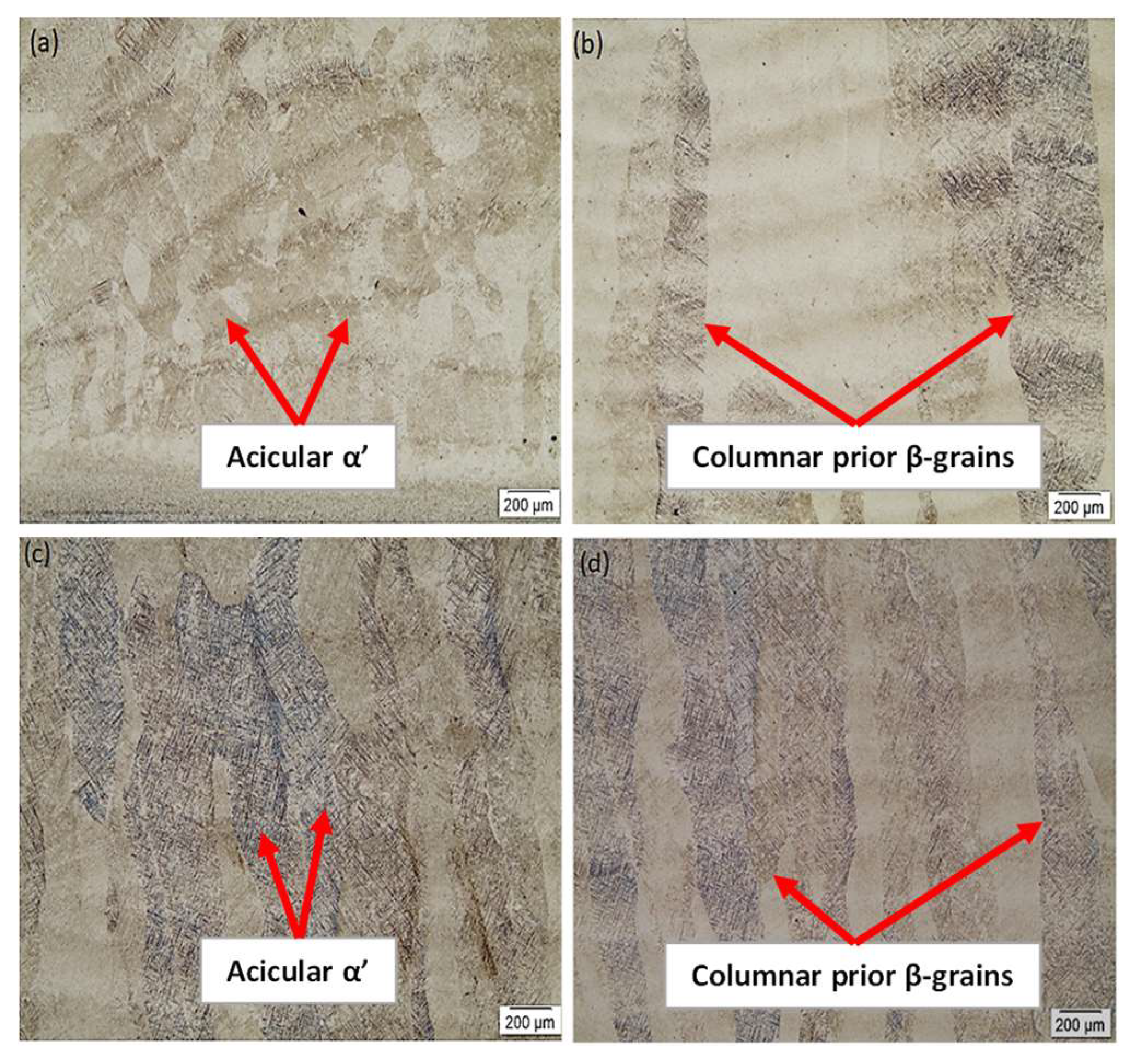
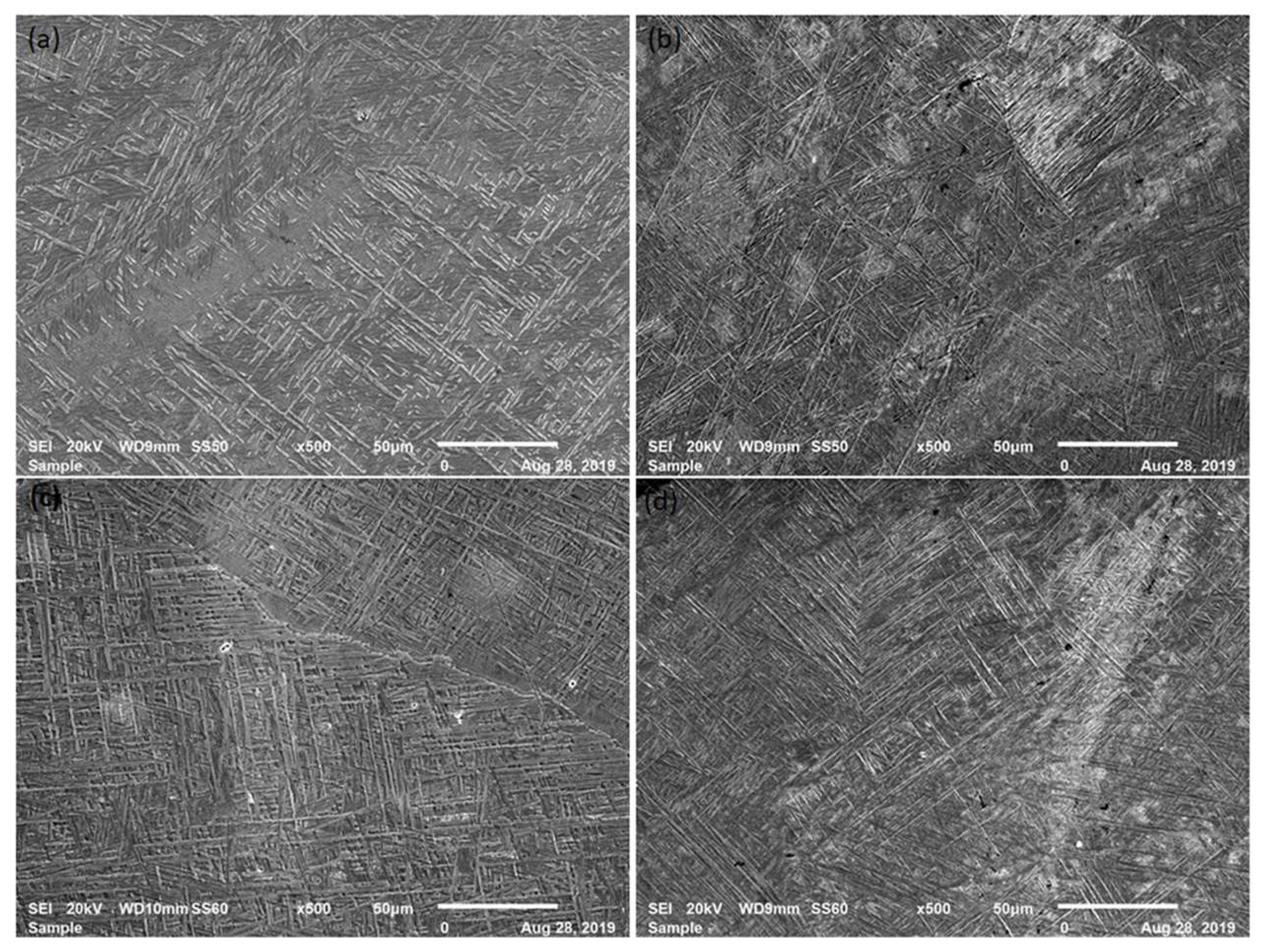
Figure 2 and Figure 3 indicate the optical micrographs and SEM images, respectively, of the LENS-fabricated Ti alloy produced at varying energy densities, i.e., 207, 249, 277, and 332 J/mm3. As is commonly found in the literature, such as the works produced by Arthur et al. [33], Shunmugavel, Polishetty, and Littlefair [6] and Vrancken et al. [34], the Ti-6Al-4V samples produced were characterised by a two-phase α–β martensitic microstructure. From a visual inspection of the micrographs (Figure 2), the formation of columnar prior beta grains was observed, which appeared to be more pronounced as the energy density was increased. The occurrence of these columnar prior beta grains is reported to be a result of epitaxial growth due to the 3D-printing process [6]. Furthermore, a fine acicular α’ martensitic microstructure was observed within these columnar grains as it becomes more pronounced. This is typically referred to as the Widmanstätten or basket-weave microstructure [33]. Figure 3 shows SEM micrographs that clearly show the structure and arrangement of the acicular martensite. The occurrence of the less-pronounced or shorter columnar grains (Figure 2a) was attributed to low energy input, which prevents a layer from being fully melted or re-melting the layer directly beneath it [35]. Furthermore, the grains are prevented from spreading out uniformly from one layer to another due to poor melting, which causes the reduced flowability of the material, thus resulting in an inhomogeneous microstructure with less than ideal and inconsistent mechanical properties [36].
The observation of the basket-weave (or Widmanstätten) microstructure is more evident in Figure 3, which indicates the SEM images of the fabricated Ti alloy. According to Arthur et al. [33] and Gasper [37], this microstructure forms due to an increase in the cooling rate of the α-β alloy and is linked to a decrease in grain size. This led to the resolution that the fabricated alloy would likely show elevated strength, since according to the Hall–Petch relation [38], a decrease in grain size is associated with an increase in strength of the material.
Table 2 shows the hardness data for the Ti alloys presented in Figure 2 and Figure 3. The indents were taken along the longitudinal build direction from the top of the sample to the bottom, where the 3D-printed sample was fused with the build plate. The wide range of indentation values shows the extent of inhomogeneity observed, due to the nature of the laser printing process, as it experiences localised energy input during the layer-by-layer build-up process [39,40]. The samples produced at an energy density of 207 and 249 J/mm3 did not show a statistical significance as they showed hardness values of 379 ± 15 and 375 ± 17 HV0.3, respectively. An increase in energy density from 249 to 277 J/mm3 was associated with a reduction in the hardness value from 375 ± 17 HV0.3 to 353 ± 11 HV0.3, which showed some statistical significance. However, upon a further increase in energy density to 332 J/mm3, the alloy showed an increase in value to 368 ± 12 HV0.3.
The difference in microhardness values reported for the alloys produced at the energy densities of 207, 249, and 332 J/mm3 is negligible, since they did not show any statistical significance. Furthermore, the alloys produced at 277 and 332 J/mm3 experienced challenges during fabrication, as the high heat inputs resulted in occasional nozzle blockage, which prevented consistent material deposition. This could potentially result in the evolution of defects, particularly during extended processing times, which could result in mechanical property inconsistencies. It was, thus, recommended that the parameter set that resulted in an energy density of 249 J/mm3 be selected as the preferred set of parameters to treat the Ti-6Al-4V alloy.

3.2. Electrochemical Behaviour

The electrochemical response of the Ti alloy was tested prior to LSP treatment. Since the starting microstructures of DED-produced parts differ from those of other manufacturing techniques, it is anticipated that there would be a difference in the properties exhibited by the same alloy when parts are produced using different techniques [41]. Therefore, wrought material was acquired to examine any difference in the electrochemical response of the Ti alloy, based on the manufacturing technique.
It is worth noting that the corrosion parameters of interest were the corrosion potential (Ecorr, V), which is identified as the potential at which no net current in or out of the electrode is observed, while the corrosion current density (icorr, A/cm2) is said to be the amount of current that flows over a cross-sectional area of a material. The corrosion rate (mm/yr) indicates the amount of material that corrodes over a specified time period, and the polarisation resistance measures the rate at which the material will experience corrosion. These parameters are used to describe the corrosion behaviour of the material.
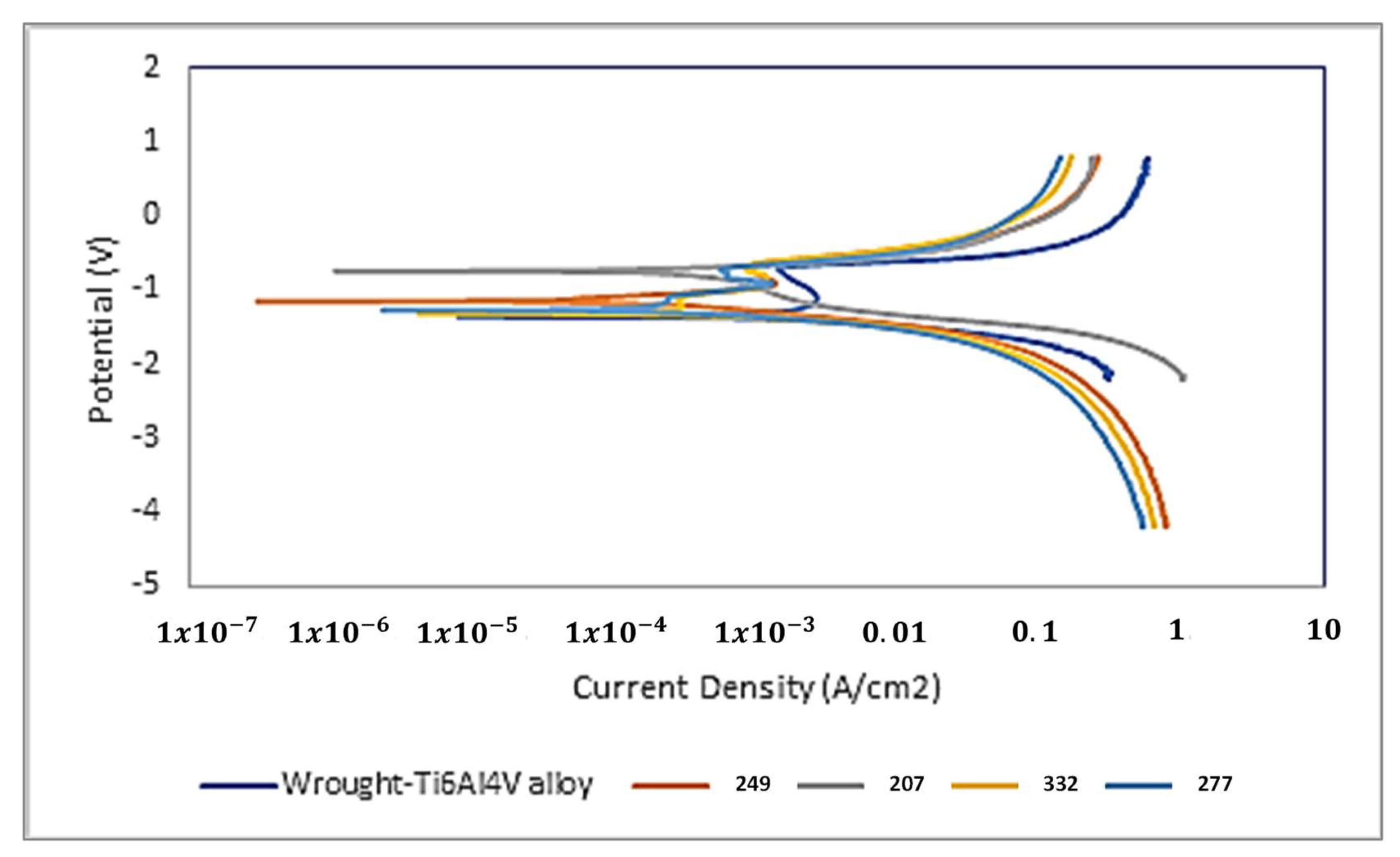
Table 3 and Table 4 show the Tafel data from the electrochemical experiments and polarisation curves, respectively, for the wrought and LENS 3D-printed Ti-6Al-4V alloys. The samples were tested in a 3.65 % NaCl solution to simulate a typical corrosive environment that the material could be exposed to during service. In terms of the corrosion parameters, it was observed from Table 3 that the wrought material showed the lowest corrosion potential of −1.3587 V at a current density of 0.003224 A/cm2, while the sample produced at 249 J/mm3 showed the highest corrosion potential of −0.74068 V at a current density of 0.000842 A/cm2. Similarly, the 249 J/mm3 alloy showed the best corrosion rate (0.32466 mm/yr) and polarisation resistance (193.27 Ω). Although the alloy produced at 332 J/mm3 showed the next best corrosion rate of 0.3291 mm/yr, it was the alloy produced at 207 J/mm3 that showed the next best polarisation resistance, at a value of 168.78 Ω.
Figure 4 shows the polarisation curves from the experiments of the alloys produced at the different energy densities, which illustrates the material behaviour or performance, based on the change in potential. The five materials tested showed similar trends, whereby, initially, a high current density was observed, but at lower corrosion potential values. The current density rapidly began to decrease once the potential was increased, until a steady state was achieved. In this state, there was no further significant increase in potential observed, even as the current density continued to decrease, thus creating a curve that could be described as the shape of the letter “J”.
It is at this point in the polarisation curve that a passive layer is reported to form [42,43], which offers additional material protection against corrosion [44]. The passive layer continued to grow in thickness (2 to 10 nm thick) and triggered an increase in potential once again, except this time, the increase in potential was associated with an increase in current density. This stage in the process gives vital information, such as the rate at which corrosion takes place in the material and how effective the material is at resisting the action of corrosion. It was reported in the literature by Sun et al. [14], Zhang et al. [21], and Hu et al. [45] that the presence of a fine microstructure contributes substantially to the corrosion resistance of the material. Therefore, it can be postulated that the improvement in the polarisation resistance of the alloys reported in Table 3 could be attributed to a refined microstructure that evolved in the alloys. Wrought Ti-6Al-4V alloys are reported to possess coarser microstructures than AM-produced alloys [6], and thus, it was anticipated that the wrought material would show the lowest polarisation resistance.
The two alloys produced in the energy density range of 200 to 250 J/mm3 (considered low-energy input) showed the highest polarisation resistances of 193.27 Ω (249 J/mm3) and 168.78 Ω (207 J/mm3), which were attributed to a higher cooling rate experienced compared to that of the two alloys produced in the energy density range of 251 to 350 J/mm3 (332 J/mm3 showed 137.32 Ω, while 277 J/mm3 showed 117.06 Ω) and, thus, evolved a finer microstructure. The energy density range of 251 to 350 J/mm3 was considered the high-energy input, for the purposes of this study, and showed lower cooling rates (associated with coarser microstructures).
The results from the electrochemical response investigations compared well with the reported results of microstructural characterisation, which identified the energy density of 249 J/mm3 as the preferred choice for the treatment of the Ti-6Al-4V alloy. Therefore, the subsequent results presented focused on the processing and treatment of the samples produced at an energy density of 249 J/mm3.

3.3. Oxidation Behaviour

Figure 5 shows the thermogravimetric analysis (TGA) curves of the LENS-fabricated samples produced at an energy density of 249 and 277 J/mm3, which showed the best and worst polarisation resistance (and corrosion rates), respectively. The samples were heated from room temperature to 800 °C at a rate of 10 °C/min in dry air. The specimens showed a similar behaviour, as observed from the two plots, whereby they were observed to be relatively stable from room temperature (approximately 85.5 mg) to about 350 to 400 °C, whereby weight gain was observed from approximately 400 to 450 °C. The literature by Güleryüz and Cimenoglu [46] reported the thickness of the oxide layer to show a substantial increase at temperatures above 200 °C as this is known to be the temperature range of the oxygen diffusion zone.
The alloys were observed to obey the parabolic law between the temperature range from approximately 450 to 550 °C, as a slight drop in weight was shown. This is consistent with the literature by Khanna [47], which stated that the rate of the oxidation reaction of engineering alloys is inversely proportional to the weight of the layer of oxide formed. This implies that the rate of scale formation decreases due to an increase in oxidation resistance. Thereafter, a sharp increase in weight gain was observed as the temperature was increased to 800 °C. It is important to note that the alloy fabricated at the energy density of 249 J/mm3 showed a superior polarisation resistance and corrosion rate in comparison to that at 277 J/mm3, thus showing lower oxide layer weight gain and, ultimately, a better oxidation response (or corrosion behaviour) for the same temperature range.
According to Czarnecki [48], the instability in the thermogravimetric graphs is mainly due to gas-related disturbances, such as drag (flow) and buoyancy (floatation). At temperatures above 750 °C, there is a transition from a parabolic to a linear law, indicating that the oxide layer is spalling off, thus increasing the oxidation rate.

3.4. Laser Shock Processing

Due to its satisfactory performance in terms of the results reported from the microstructural characterisation and electrochemical and oxidation behaviour, the parameter set that resulted in an energy density of 249 J/mm3 (refer to Table 1) was selected as the optimised parameter set for the investigations. Thus, the subsequent results presented from the laser shock processing investigations were performed on the sample that was fabricated at the optimised parameter set alone, having an energy density of 249 J/mm3.
Figure 6 displays the optical microstructures of the LENS-built specimens (produced at the optimised parameters) in the as-built state without peening (Image (a)) and after laser shock peening treatment at 90% (Image (b)), 95% (Image (c)) and 99% (Image (c)) overlap, respectively.
Tensile stresses created during LENS fabrication weakened the mechanical properties, and as a result, the fabricated samples were subjected to post-processing techniques to relieve the residual stresses [49]. Since laser peening is a surface-acting technique that penetrates about 1 mm into the material, the process induces beneficial compressive stresses. Its effect is more readily observed towards the surface of the treated material. Figure 6 presents the Ti-6Al-4V alloys fabricated at an energy density of 249 J/mm3, before and after LSP treatment. Image (a) represents the un-peened sample, while Images (b–d) represent the 90%, 95%, and 99% peening overlaps, respectively. The region marked by the red arrows indicates the anticipated penetration depth of the LSP treatment. From a visual inspection, there was no observable change in microstructure, so it cannot be concluded that LSP treatment has a significant impact on the appearance of the microstructure. Similarly, no noticeable difference was observed through the SEM analysis. This would, therefore, find greater relevance when subsequent investigations such as corrosion and oxidation studies are presented, as it would highlight the changes in material performance due to LSP treatment.
However, the samples revealed a typical microstructure observed for DED laser-printed samples that show microstructural inhomogeneity, which is commonly referred to as fish-scaling. The fish-scaling forms when the melt pool shape changes and depicts overlapping weld beads. Similarly, this type of microstructure was reported in the studies by Arthur et al. [31] and Choo et al. [50].

3.4.1. Influence of Laser Peening on Microhardness and Surface Roughness

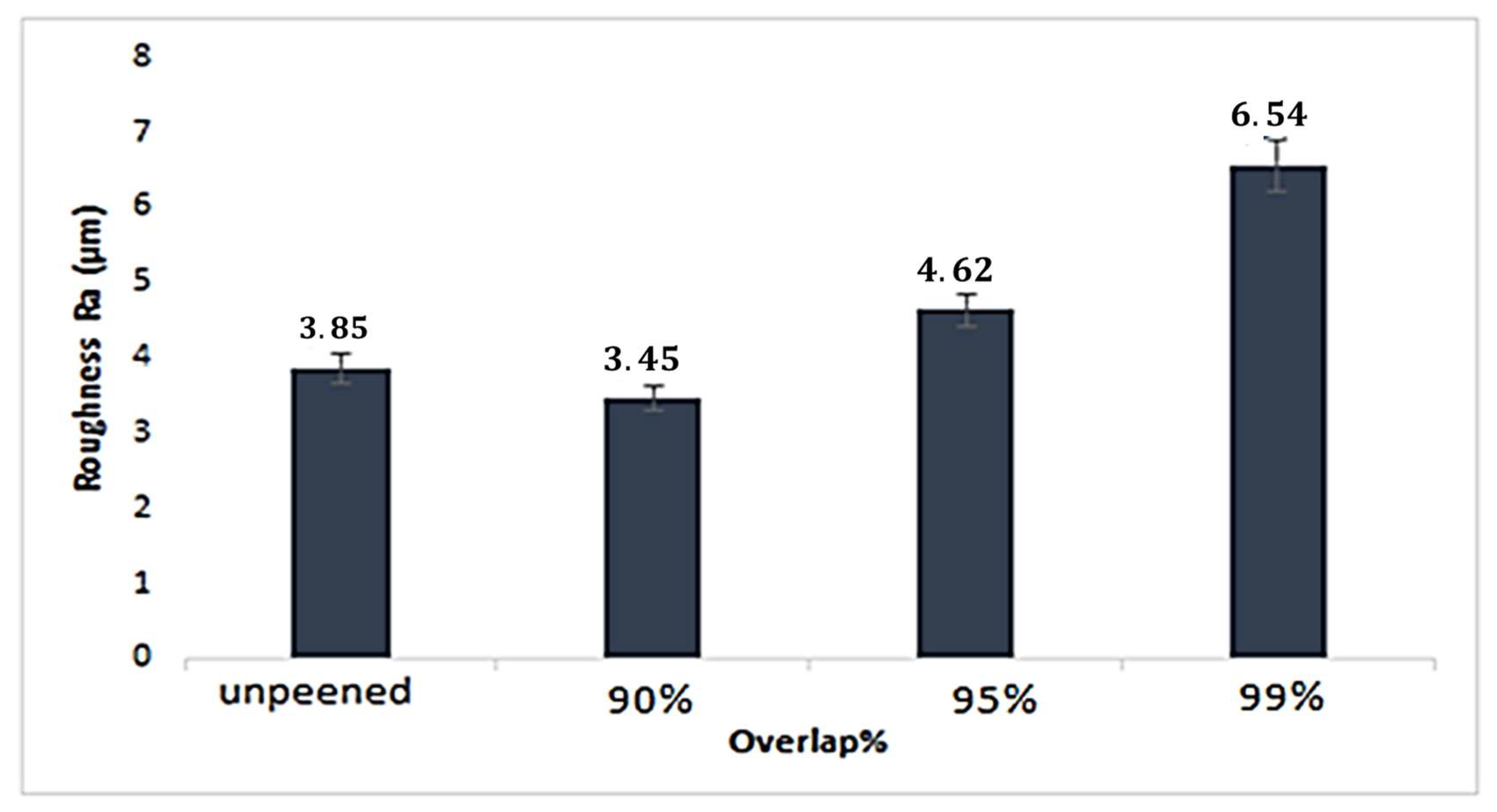
Microhardness and surface roughness tests were carried out to study the surface-strengthening effect induced by the LSP process. The results thereof are shown in Table 4 and Figure 7, respectively. The top surface of the 3D-printed specimens is the region where the LSP treatment was applied. It was observed that the material hardness increased due to laser shock processing treatment; however, although there was a slight variation in hardness due to an increase in laser peening overlap, this did not show a significant overall increase. It must, however, be noted that the slight variation in material hardness could potentially result in an improvement in corrosion resistance, as previously reported.
The observed increase in the hardness profile after LSP treatment confirmed the success of the process to show that compressive residual stresses were induced in the specimens’ surfaces. This is seen by the difference in the average hardness values reported for the different specimens in Table 4, whereby the LSP-treated specimens showed hardness values in the range of 384 to 389 HV, whereas the untreated specimen shoed a hardness value of 375 HV. However, no statistical significance could be established, which suggested that there was no significant change in phase transformation due to the LSP treatment.
The hardness at the top region of the peened samples was observed to be higher than that of the core and lower regions of the samples, thus confirming the top region to exhibit more compressive stresses, while the core and lower regions of the specimens showed more tensile stresses. This compares well with the literature by Arthur et al. [51], which reported lower hardness values for the greater tensile stress regions of samples, which were analysed for stress magnitudes by using neutron diffraction, while higher hardness was reported for the greater compressive stress regions of the DED-fabricated Ti-6Al-4V samples. Since LSP generates shock waves, the hardness is expected to decrease with depth within the sample for treated sections as compared to untreated sections. This observation was consistent between the different specimens tested and compares well with the literature by Guo et al. [15] and Luo et al. [52], which reported similar observations in the hardness profile due to the influence of laser shock processing.
In addition, an investigation by Karthik et al. [27] corroborated the present observations as it reported a similar observation for AISI 321 steel that had been processed using the LSPwC configuration, whereby the treated section of the material showed hardness values in the range of approximately 150 to 175 HV from the top layer and down to a depth of roughly 400 μm. A further increase in depth from 400 μm to about 800 μm showed a steady decrease in the hardness profile from about 150 HV to roughly 130 HV. From a depth of about 900 to 1400 μm, which was the remaining depth of the sample, the hardness values showed a negligible change (approximately 127 HV). This was also the region reported to be untreated, as it fell outside of the “depth of the hardened layers” and showed no significant change in hardness value. This suggests that the reported change in hardness with the depth of the treated samples may not be material-dependent, as was reported by Kanjer et al. [24], whereby the investigators found no gradient in the hardness profiles from the surface to the core of the material for their CP-Ti samples.
Table 4. Microhardness values of laser-peened samples, (HV0.3).
before LSPafter LSP
249 J/mm390%95%99%
Maximum399438427425
Minimum303356359352
Average375384386389
STD dev17161216
Furthermore, it was observed that an increase in LSP overlap was associated with an increase in surface roughness (as indicated in Figure 7), which affects the material properties, as it could serve as nucleation sites for cracks or corrosion attack. An initial decrease in roughness of about 10% was observed between the un-peened (3.85 Ra) and 90%-overlap (3.45 Ra) samples, as seen in Figure 7. This was favourable as it suggested an improvement in the surface properties of the material. Upon a further increase in overlap from 90% to 95% (4.62 Ra), there was an increase in roughness of approximately 30%, but a further increase from 95% to 99% (6.54 Ra) showed a significant influence on the surface roughness, as the roughness increased by more than 40% to 6.54 Ra.
The results showed that the surface properties were impacted due to LSP treatment. When an LSP overlap of 90% and 95% was used to treat the Ti-6Al-4V alloy, this resulted in an increase in the roughness of up to 20%, in relation to the untreated specimen. The use of overlap in excess of 95% showed a substantial increase in surface roughness (up to 70%) in relation to the untreated specimen. Based on this observation, it is advisable that the overlap percentage be kept between the range of 90 and 95% to mitigate any potential negative impact on properties that could be associated with such a substantial increase in the surface properties.
A mechanical property, such as fatigue life, is known to be sensitive to the surface properties of the tested specimen; thus, an observed decrease in the surface properties would be more favourable to the fatigue life of the material.

3.4.2. Influence of Laser Peening on Electrochemical Response

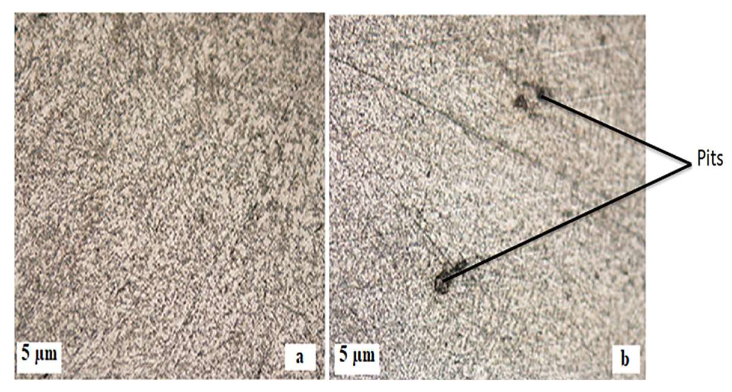
The corrosion behaviour of laser-peened specimens was tested and compared to that of the as-built specimen to investigate if there would be a noticeable difference. Evidence of pitting corrosion was observed before and after LSP treatment; however, it was observed that the LSP-treated specimens showed fewer pits and, in some cases, smaller-sized pits than in the case of the untreated specimen. Figure 8 shows the optical micrographs of the typical sample surfaces observed for the corrosion-tested alloys. Image (b) presents the sample before LSP treatment, with the presence of pitting corrosion evident, while Image (a) presents the LSP-treated sample with no evidence of pitting corrosion. The reduced presence of pits was attributed to the property improvements induced in the material surface due to the introduction of compressive residual stresses, therefore demonstrating an improvement in corrosion resistance.
The polarisation curves were analysed to determine the corrosion parameters and confirm the extent of change brought about due to the LSP treatment. Table 5 shows the Tafel data for the corrosion parameters of the peened and un-peened specimens, while the polarisation curves are shown in Figure 9. The observation made was that there was a significant improvement in the corrosion response after laser peening. The sample treated at a 95% overlap showed the best performance of the alloys, with the best corrosion rate and polarisation resistance of 0.003 mm/yr and 119,730 Ω, respectively. The alloy treated at 90% overlap showed the second-best performance, with a corrosion rate and polarisation resistance of 0.004 mm/yr and 40,932 Ω, respectively. The alloy treated at an overlap of 99% showed the lowest polarisation resistance of 12,220 Ω, but showed a greater corrosion rate in comparison to the un-peened sample, which showed the lowest corrosion rate of 0.063 mm/yr. It is likely that the high surface roughness previously reported for the 99% overlap could have influenced the polarisation resistance and affected the corrosion rate by creating possible sites for corrosion attack. It was, therefore, postulated that the overlap percentage be limited to the range of 90% to 95% to ensure optimum corrosion performance and to minimise the possibility of the inconsistency of the corrosion parameters, such as the corrosion rate and polarisation resistance.

3.4.3. Influence of Laser Peening on Oxidation Behaviour

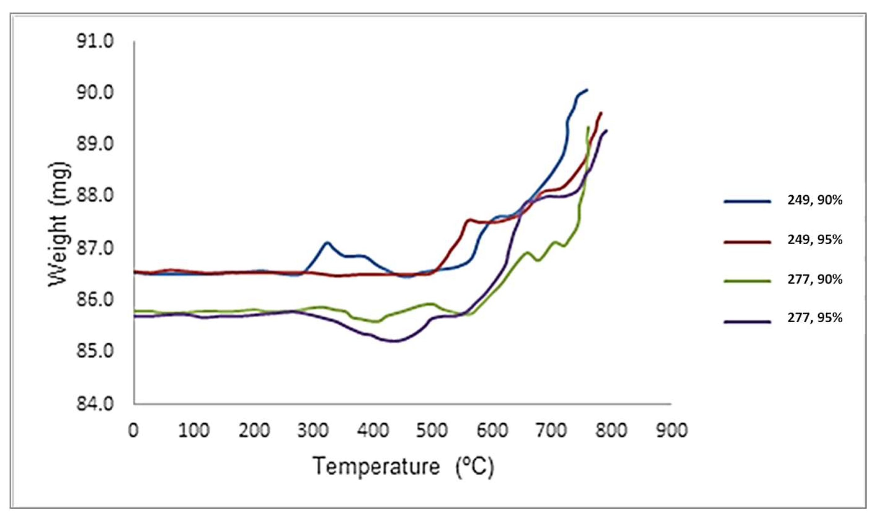
The following section presents results for samples produced at an energy density of 249 and 277 J/mm3, which showed the best and worst polarisation resistance (and corrosion rates), respectively. Similar to the results presented in Figure 5, found in Section 3.3 (Oxidation Behaviour), the alloys were compared to investigate the influence of laser peening and to see if there would be a marked improvement in oxidation performance. Furthermore, the results were limited to that of the LSP overlaps that showed good performance for both the corrosion rate and polarisation resistance, namely the 90% and 95% alloys.
Figure 10 presents the TGA results of the alloys produced at an energy density of 249 and 277 J/mm3 after LSP treatment at 90% and 95% overlap each. The alloys produced at 277 J/mm3 and treated with 90% and 95% overlap showed slight stability from room temperature (approximately 85.5 mg) to about 300 °C. Thereafter, a decrease in weight was observed until a temperature of about 450 °C, whereby it then picked up as the temperature was increased to 800 °C, with a weight of approximately 89 mg. No significant difference was observed in the oxidation behaviour of this alloy due to the influence of the LSSP treatment; however, the 249 J/mm3 alloy showed a more significant difference in oxidation behaviour as a result of the applied LSP treatment.
The 249 J/mm3 alloy with 95% overlap showed greater stability than its 90% counterpart, up to a temperature of roughly 500 °C from room temperature (starting weights of approximately 86.5 mg), which was also the best stability of the alloys tested. A gradual increase in weight gain was observed as the temperature was increased from 500 °C to 800 °C, with a final weight of roughly 89.5 mg. The alloy treated at 90% overlap showed a slightly higher weight gain of roughly 90 mg as the final temperature of 800°C was reached. The 249 J/mm3 alloy with 95% overlap had better oxidation resistance as compared to the other samples with minimal weight gain. The sample also showed better corrosion resistance. This confirmed that LSP treatment can effectively enhance the oxidation resistance of AM-produced components.

4. Conclusions

In this study, Ti-6Al-4V alloy samples were successfully fabricated using the LENS DED technique. LSP treatment was applied as a post-processing surface treatment to enhance the material properties. The following conclusions were drawn based on the results from this study:
  • The energy input, measured as the energy density, had a positive effect on the microstructural evolution as it reduced the formation of defects, which resulted in improved mechanical properties.
  • The energy density of 249 J/mm3 used to fabricate the Ti-6Al-4V samples was seen to be sufficient to treat the alloy and evolve microstructures that showed beneficial properties.
  • The typical microstructure observed for the Ti-6Al-4V alloy was reported to be the fine acicular α’ martensitic microstructure, which was reported to promote improved corrosion resistance.
  • Optimum corrosion and oxidation behaviour was observed with the alloy produced at the optimised parameters that gave an energy density of 249 J/mm3. Therefore, it is recommended for the energy density to be kept at moderate levels to treat the Ti-6Al-4V alloy and ensure improved corrosion and oxidation response.
  • The use of LSP as a surface treatment technique was demonstrated to yield improvements in the mechanical properties, such as the surface hardness profile, through the introduction of compressive residual stresses. It is postulated that, through this, the fatigue properties could potentially be improved as well.
  • The application of the LSP technique at varying overlaps demonstrated the strong capability of the technique for the improvement of the corrosion performance of the Ti-6Al-4V alloy, as well as the mitigation of pitting corrosion.
  • The use of LSP overlaps should be maintained at a moderate level not exceeding 95%, to minimise the effects on the surface properties, but still optimising the material properties, such as the corrosion rate and polarisation resistance, and to promote an improved oxidation rate and stability during operation at elevated temperatures up to 500 °C.

Author Contributions

Methodology, S.M.K., B.N.M. and N.K.K.A.; writing—original draft preparation, S.M.K. and N.K.K.A.; writing—review and editing, S.M.K. and N.K.K.A.; supervision, A.P.I.P. and S.L.P.; funding acquisition, A.P.I.P., S.L.P. and N.K.K.A. All authors have read and agreed to the published version of the manuscript.

Funding

The additive manufacturing research of the CSIR’s Photonics Center was funded by DSI through the CPAM project (Project Code: HLHC21X). Funding for this work was provided though the CPAM project, under the cost code of HLM3NAX within the LEM research group.

Data Availability Statement

Data available on request due to privacy restrictions.

Acknowledgments

The authors would like to acknowledge the CSIR’s Photonics Center (PC) Laser Enabled Manufacturing (LEM) research group for sample preparation and characterisation. The following people are acknowledged for their support: Paul Lekoadi and Khoro Malabi.

Conflicts of Interest

The authors declare no conflict of interest.

References

  1. Oliari, S.H.; D’Oliveira, A.S.C.M.; Schulz, M. Additive Manufacturing of H11 with Wire-Based Laser Metal Deposition. Soldag. Inspeção 2017, 22, 466–479. [Google Scholar] [CrossRef]
  2. Sibisi, P.N.; Popoola, A.P.I.; Arthur, N.K.K.; Pityana, S.L. Review on Direct Metal Laser Deposition Manufacturing Technology for the Ti-6Al-4V Alloy. Int. J. Adv. Manuf. Technol. 2020, 107, 1163–1178. [Google Scholar] [CrossRef]
  3. Inagaki, I.; Shirai, Y.; Takechi, T.; Ariyasu, N. Application and Features of Titanium for the Aerospace Industry. 2014. Available online: https://www.nipponsteel.com/en/tech/report/nssmc/pdf/106-05.pdf (accessed on 16 April 2023).
  4. Sharif, S.; Rahim, E.A.; Sasahara, H. Machinability of Titanium Alloys in Drilling. In Titanium Alloys—Towards Achieving Enhanced Properties for Diversified Applications; Intech: Sydney, Australia, 2013. [Google Scholar]
  5. Revankar, G.D.; Shetty, R.; Rao, S.S.; Gaitonde, V.N. Analysis of Surface Roughness and Hardness in Titanium Alloy Machining with Polycrystalline Diamond Tool under Different Lubricating Modes. Mater. Res. 2014, 14, 1010–1022. [Google Scholar] [CrossRef]
  6. Shunmugavel, M.; Polishetty, A.; Littlefair, G. Microstructure and Mechanical Properties of Wrought and Additive Manufactured Ti-6Al-4V Cylindrical Bars. Procedia Technol. 2015, 20, 231–236. [Google Scholar] [CrossRef]
  7. Peters, M.; Kumpfert, J.; Ward, C.H.; Leyens, C. Titanium Alloys for Aerospace Applications. In Titanium and Titanium Alloys: Fundamentals and Applications; WILEY-VCH Verlag GmbH & Co. KGaA: Weinheim, Germany, 2001; pp. 333–350. [Google Scholar]
  8. Neikter, M.; Åkerfeldt, P.; Pederson, R.; Antti, M.L.; Sandell, V. Microstructural Characterization and Comparison of Ti-6Al-4V Manufactured with Different Additive Manufacturing Processes. Mater. Charact. 2018, 143, 68–75. [Google Scholar] [CrossRef]
  9. Casadebaigt, A.; Monceau, D.; Hugues, J. High Temperature Oxidation of Ti-6Al-4V Alloy Fabricated by Additive Manufcturing: Influence on Mechanical Properties. In MATEC Web of Conferences; EDP Sciences: Les Ulis, France, 2020; Volume 321, p. 03006. [Google Scholar]
  10. Eylon, D.; Fujishiro, S.; Postans, P.J.; Froes, F.H. High-Temperature Titanium Alloys: A Review. J. Metals 1984, 36, 55–62. [Google Scholar] [CrossRef]
  11. Gaddam, R.; Sefer, B.; Pederson, R.; Antti, M.L. Study of Alpha-Case Depth in Ti-6Al-2Sn-4Zr-2Mo and Ti-6Al-4V. IOP Conf. Ser. Mater. Sci. Eng. 2013, 48, 012002. [Google Scholar] [CrossRef]
  12. Sefer, B.; Roa, J.J.; Mateo, A.; Pederson, R.; Antti, M.L. Evaluation of the Bulk and Alpha-Case Layer Properties in Ti-6Al-4V at Micro- and Nano-Metric Length Scale. In Proceedings of the 13th World Conference on Titanium; John Wiley & Sons, Inc.: Hoboken, NJ, USA, 2016; pp. 1619–1624. [Google Scholar]
  13. Liao, Y.; Ye, C.; Cheng, G.J. A Review: Warm Laser Shock Peening and Related Laser Processing Technique. Opt. Laser Technol. 2016, 78, 15–24. [Google Scholar] [CrossRef]
  14. Sun, R.; Li, L.; Zhu, Y.; Guo, W.; Peng, P.; Cong, B.; Sun, J.; Che, Z.; Li, B.; Guo, C.; et al. Microstructure, Residual Stress and Tensile Properties Control of Wire Arc Additive Manufactured 2319 Aluminum Alloy with Laser Shock Peening. J. Alloys Compd. 2018, 747, 255–265. [Google Scholar] [CrossRef]
  15. Guo, W.; Wang, H.; Peng, P.; Song, B.; Zhang, H.; Shao, T.; Huan, H.; Qiao, H.; Qu, G.; Zhu, D.; et al. Effect of Laser Shock Processing on Oxidation Resistance of Laser Additive Manufactured Ti6Al4V Titanium Alloy. Corros. Sci. 2020, 170, 108655. [Google Scholar] [CrossRef]
  16. Peyre, P.; Fabbro, R. Laser Shock Processing: A Review of the Physics and Applications. Opt. Quantum Electron. 1995, 27, 1213–1229. [Google Scholar]
  17. Clauer, A.H.; Peening, L.S. Review: Laser Shock Peening, the Path to Production. Metals 2019, 9, 626. [Google Scholar] [CrossRef]
  18. Sano, Y.; Akita, K.; Masaki, K.; Ochi, Y.; Altenberger, I.; Scholtes, B. Laser Peening without Coating as a Surface Enhancement Technology. Pulse 2006, 100, 250mJ. [Google Scholar] [CrossRef]
  19. Sano, Y. Quarter Century Development of Laser Peening without Coating. Metals 2020, 10, 152. [Google Scholar] [CrossRef]
  20. Shukla, P.P.; Swanson, P.T.; Page, C.J. Laser Shock Peening and Mechanical Shot Peening Processes Applicable for the Surface Treatment of Technical Grade Ceramics: A Review. J. Eng. Manuf. 2013, 228, 639–652. [Google Scholar] [CrossRef]
  21. Zhang, Q.; Duan, B.; Zhang, Z.; Wang, J.; Si, C. Effect of ultrasonic shot peening on microstructure evolution and corrosion resistance of selective laser melted Tie6Ale4V alloy. J. Mater. Res. Technol. 2021, 11, 1090–1099. [Google Scholar] [CrossRef]
  22. Agrawal, R.K.; Pandey, V.; Barhanpurkar-Naik, A.; Wani, M.R.; Chattopadhyay, K.; Singh, V. Effect of Ultrasonic Shot Peening Duration on Microstructure, Corrosion Behavior and Cell Response of CP-Ti. Ultrasonics 2020, 104, 106110. [Google Scholar] [CrossRef]
  23. Crespo, L.; Hierro-Oliva, M.; Barriuso, S.; Vadillo-Rodríguez, V.; Montealegre, M.Á.; Saldaña, L.; Gomez-Barrena, E.; González-Carrasco, J.L.; González-Martín, M.L.; Vilaboa, N. On the Interactions of Human Bone Cells with Ti6Al4V Thermally Oxidized by Means of Laser Shock Processing. Biomed. Mater. 2016, 11, 015009. [Google Scholar] [CrossRef]
  24. Kanjer, A.; Lavisse, L.; Optasanu, V.; Berger, P.; Gorny, C.; Peyre, P.; Herbst, F.; Heintz, O.; Geoffroy, N.; Montesin, T.; et al. Effect of Laser Shock Peening on the High Temperature Oxidation Resistance of Titanium. Surf. Coat. Technol. 2017, 326, 146–155. [Google Scholar] [CrossRef]
  25. Berthe, L.; Fabbro, R.; Peyre, P.; Tollier, L.; Bartnicki, E. Shock Waves from a Water-Confined Laser-Generated Plasma. J. Appl. Phys. 1997, 82, 2826–2832. [Google Scholar] [CrossRef]
  26. Maawad, E.; Sano, Y.; Wagner, L.; Brokmeier, H.-G.; Genzel, C. Investigation of Laser Shock Peening Effects on Residual Stress State and Fatigue Performance of Ttanium Aloys. Mater. Sci. Eng. A 2012, 82–91, 536. [Google Scholar]
  27. Karthik, D.; Swaroop, S. Laser Peening without Coating Induced Phase Transformation and Thermal Relaxation of Residual Stresses in AISI 321 Steel. Surf. Coat. Technol. 2016, 291, 161–171. [Google Scholar] [CrossRef]
  28. Sathyajith, S.; Kalainathan, S.; Swaroop, S. Laser Peening without Coating on Aluminum Alloy Al-6061-T6 Using Low Energy Nd:YAG Laser. Opt. Laser Technol. 2013, 45, 389–394. [Google Scholar] [CrossRef]
  29. Sano, Y.; Masaki, K.; Gushi, T.; Sano, T. Improvement in Fatigue Performance of Friction Stir Welded A6061-T6 Aluminum Alloy by Laser Peening without Coating. Mater. Des. 2012, 36, 809–814. [Google Scholar] [CrossRef]
  30. Attar, H.; Bonisch, M.; Calin, M.; Zhang, L.C.; Scudino, S.; Eckert, J. Selective Laser Melting of In Situ Titanium-Titanium Boride Composites: Processing, Microstructure and Mechanical Properties. Acta Mater. 2014, 76, 13–22. [Google Scholar] [CrossRef]
  31. Arthur, N.K.K.; Siyasiya, C.W.; Pityana, S.L.; Tlotleng, M. Microstructural Response of Ti6Al4V ELI Alloyed with Molybdenum by Direct Energy Deposition. J. Mater. Eng. Perform. 2021, 30, 5455–5465. [Google Scholar] [CrossRef]
  32. Arthur, N.K.K.; Pityana, S.L. Microstructure and Material Properties of LENS Fabricated Ti6Al4V Components. R D J. S. Afr. Inst. Mech. Eng. 2018, 34, 33–36. [Google Scholar]
  33. Arthur, N.K.K. Laser Based Manufacturing of Ti6Al4V: A Comparison of LENS and Selective Laser Melting. Mater. Sci. Forum 2019, 950, 44–49. [Google Scholar] [CrossRef]
  34. Vrancken, B.; Thijs, L.; Kruth, J.-P.; Van Humbeeck, J. Heat Treatment of Ti6Al4V Produced by Selective Laser Melting: Microstructure and Mechanical Properties. J. Alloys Compd. 2012, 541, 177–185. [Google Scholar] [CrossRef]
  35. Yi, J.H.; Kang, J.W.; Wang, T.J.; Wang, X.; Hu, Y.Y.; Feng, T.; Feng, Y.L.; Wu, P.Y. Effect of Laser Energy Density on the Microstructure, Mechanical Properties, and Deformation of Inconel 718 Samples Fabricated by Selective Laser Melting. J. Alloys Compd. 2019, 786, 481–488. [Google Scholar] [CrossRef]
  36. Wang, X.; Kang, J.; Wang, T.; Wu, P.; Feng, T.; Zheng, L. Effect of Layer-Wise Varying Parameters on the Microstructure and Soundness of Selective Laser Melted INCONEL 718 Alloy. Materials 2019, 12, 2165. [Google Scholar] [CrossRef] [PubMed]
  37. Gasper, B. Microstructural Characterisation of Ti6Al4V and Its Relationship to Sample Geometry; Materials Engineering Department, California Polytechnic State University: San Luis Obispo, CA, USA, 2012. [Google Scholar]
  38. Hansen, N. Hall–Petch Relation and Boundary Strengthening. Scr. Mater. 2004, 51, 801–806. [Google Scholar] [CrossRef]
  39. Dutta, B.; Froes, F.H. Additive Manufacturing of Titanium Alloys, Kidlington; Butterworth-Heinemann, Elsevier: Oxford, UK, 2016. [Google Scholar]
  40. Yan, F.; Xiong, W.; Faierson, E.J. Grain Structure Control of Additively Manufactured Metallic Materials. Materials 2017, 10, 1260. [Google Scholar] [CrossRef]
  41. Arthur, N.K.K.; Siyasiya, C.W.; Pityana, S.L.; Tlotleng, M. Heat Treatment Response and Characterization of Ti6Al4V + xMo Produced by Laser Metal Deposition. Mater. Today Proc. 2022, 62, 194–200. [Google Scholar] [CrossRef]
  42. Yerokhin, A.L.; Leyland, A.; Matthews, A. Characterisation of Oxide Films Produced by Plasma Electrolytic Oxidation of a Ti–6Al–4V Alloy. Surf. Coat. Technol. 2000, 130, 195–206. [Google Scholar] [CrossRef]
  43. Aniołek, K.; Łosiewicz, B.; Kubisztal, J.; Osak, P.; Stróz, A.; Barylski, A.; Kaptacz, S.; Properties, M. Corrosion Resistance and Bioactivity of Oxide Layers Formed by Isothermal Oxidation of Ti-6Al-7Nb Alloy. Coatings 2021, 11, 505. [Google Scholar] [CrossRef]
  44. Pouilleau, J.; Devilliers, D.; Garrido, F.; Durand-Vidal, S.; Mahe, E. Structure and composition of passive titanium oxide films. Mater. Sci. Eng. B 1997, 47, 235–243. [Google Scholar] [CrossRef]
  45. Hu, N.; Xie, L.; Liao, Q.; Gao, A.; Zheng, Y.; Pan, H.; Tong, L.; Yang, D.; Gao, N.; Starink, M.J.; et al. A More Defective Substrate Leads to a Less Defective Passive Layer: Enhancing the Mechanical Strength, Corrosion Resistance and Anti-Inflammatory Response of the Low-Modulus Ti-45Nb Alloy by Grain Refinement. Acta Biomater. 2021, 126, 524–536. [Google Scholar] [CrossRef]
  46. Güleryüz, H.; Cimenoglu, H. Oxidation of Ti–6Al–4V Alloy. J. Alloys Compd. 2009, 472, 241–246. [Google Scholar] [CrossRef]
  47. Khanna, A.S. High Temperature Oxidation. In Handbook of Environmental Degradation of Materials, 2nd ed.; Elsevier: Amsterdam, The Netherlands, 2012; pp. 127–194. [Google Scholar]
  48. Czarnecki, J.P. Precision Thermogravimetry. J. Therm. Anal. Calorim. 2015, 120, 139–147. [Google Scholar] [CrossRef]
  49. Liu, Y.; Yang, Y.; Wang, D. A Study on the Residual Stress During Selective Laser Melting (SLM) of Metallic Powder. Int. J. Adv. Manuf. Technol. 2016, 87, 647–656. [Google Scholar] [CrossRef]
  50. Choo, H.; Sham, K.-L.; Bohling, J.; Ngo, A.; Xiao, X.; Ren, Y.; Depond, P.J.; Matthews, M.J.; Garlea, E. Effect of Laser Power on Defect, Texture, and Microstructure of a Laser Powder Bed Fusion Processed 316L Stainless Steel. Mater. Des. 2019, 164, 107534. [Google Scholar] [CrossRef]
  51. Willemse, M.G.; Siyasiya, C.W.; Marais, D.; Venter, A.M. Material Characteristics of Ti-6AL-4V Samples Additively Manufactured Using Laser-Based Direct Energy Deposition. J. S. Afr. Inst. Min. Metall. 2023, 123, 93–102. [Google Scholar] [CrossRef] [PubMed]
  52. Luo, S.; He, W.; Chen, K.; Nie, X.; Zhou, L.; Li, Y. Regain the Fatigue Strength of Laser Additive Manufactured Ti Alloy via Laser Shock Peening. J. Alloys Compd. 2018, 750, 626–635. [Google Scholar] [CrossRef]
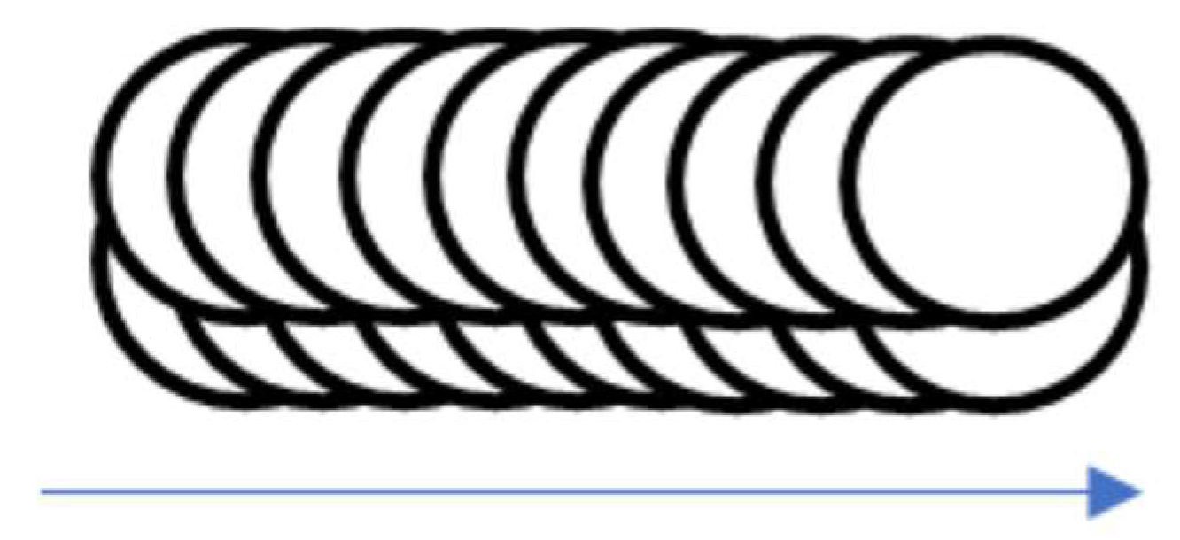
Figure 1. Schematic of the LSP overlap path.
Jcs 07 00218 g001
Figure 2. Optical micrographs of as-built LENS Ti-6Al-4V samples at energy densities of (a) 207, (b) 249, (c) 277, (d) and 332 J/mm3.
Jcs 07 00218 g002
Figure 3. SEM micrographs of as-built LENS Ti-6Al-4V samples at energy densities of (a) 207, (b) 249, (c) 277, and (d) 332 J/mm3.
Jcs 07 00218 g003
Figure 4. Polarisation curves of the wrought and LENS-built Ti-6Al-4V samples.
Jcs 07 00218 g004
Figure 5. TGA curves of the LENS samples fabricated at 249 and 277 J/mm3.
Jcs 07 00218 g005
Figure 6. Optical micrographs of samples fabricated at 249 J/mm3 with various peening treatments: (a) un-peened, (b) 90%, (c) 95% and (d) 99% peening overlap.
Jcs 07 00218 g006
Figure 7. Surface roughness of laser-shock-peened samples.
Jcs 07 00218 g007
Figure 8. LENS-fabricated Ti-6Al-4V samples: (a) LSP-treated, (b) untreated.
Jcs 07 00218 g008
Figure 9. Polarisation curves depicting corrosion response of peened and un-peened specimens.
Jcs 07 00218 g009
Figure 10. TGA curves of samples produced at 249 and 277 J/mm3 after LSP treatment at 90% and 95% overlap.
Jcs 07 00218 g010
Table 1. Parameters used for DED sample fabrication.
Laser Energy Density (J/mm3)Power (W)Scan Speed (mm/s)Hatch Spacing (mm)Layer Thickness (mm)
20730012.70.33750.3375
24930010.58
27740012.7
33240010.58
Table 2. Microhardness values of LENS-built Ti-6Al-4V samples.
Microhardness (HV0.3)
Energy Density (J/mm3)207249277332
Maximum397399377397
Minimum320303330330
Average379375353368
STD dev15171112
Table 3. Tafel data comparing wrought Ti-6Al-4V and LENS-built samples.
Samples (J/mm3)Ecorr (V)Icorr (A/cm²)Corrosion Rate (mm/yr)Polarisation Resistance (Ω)
Ti-6Al-4V Wrought−1.35870.0032241.2426102.5
207−1.15230.0014610.56302168.776
249−0.740680.0008420.32466193.27
277−1.27090.0024140.93023117.06
332−1.31680.0008540.3291137.32
Table 5. Tafel data of as-built and laser-peened samples.
TreatmentEcorr (V)Icorr (A/cm2)Corrosion Rate (mm/yr)Polarisation Resistance (Ω)
Un-peened−0.67224 4.7 × 10 5 0.06329,239
90% overlap−0.61981 5.11 × 10 6 0.00440,932
95% overlap−0.59463 3.08 × 10 6 0.003119,730
99% overlap−0.40481 4.09 × 10 6 0.00512,220
Disclaimer/Publisher’s Note: The statements, opinions and data contained in all publications are solely those of the individual author(s) and contributor(s) and not of MDPI and/or the editor(s). MDPI and/or the editor(s) disclaim responsibility for any injury to people or property resulting from any ideas, methods, instructions or products referred to in the content.