Article

Experimental Investigation on Flexural Behaviour of Sustainable Reinforced Concrete Beam with a Smart Mortar Layer

by
Ramkumar Durairaj
1,
Thirumurugan Varatharajan
2,*,
Satyanarayanan Kachabeswara Srinivasan
2,
Beulah Gnana Ananthi Gurupatham
3 and
Krishanu Roy
4,*
1
Research Scholar, Department of Civil Engineering, SRMIST, Kattankulathur 603203, India
2
Department of Civil Engineering, SRMIST, Kattankulathur 603203, India
3
Department of Civil Engineering, College of Engineering Guindy Campus, Anna University, Chennai 600025, India
4
School of Engineering, The University of Waikato, Hamilton 3216, New Zealand
*
Authors to whom correspondence should be addressed.
J. Compos. Sci. 2023, 7(4), 132; https://doi.org/10.3390/jcs7040132
Submission received: 9 February 2023 / Revised: 11 March 2023 / Accepted: 20 March 2023 / Published: 23 March 2023
(This article belongs to the Special Issue Sustainable Composite Construction Materials)

Abstract

:
This paper deals with an experimental study of the flexural behavior of sustainable reinforced cement concrete (RCC) beams with a smart mortar layer attached to the concrete mixture. In total, nine RCC beams were cast and tested. Two types of reinforced concrete beams were cast, and three different beams of sizes 1000 × 150 × 200 mm and six different beams of sizes 1500 × 100 × 250 mm were considered. The flexural behavior of these RCC beams was studied in detail. The electrical resistivity of these beams was also calculated, which was derived from the smart mortar layer. Research on the application of smart mortars within structural members is limited. The experimental results showed that the smart mortar layer could sense the damage in the RCC beams and infer the damage through the electrical measurement values, making the beam more sustainable. It was also observed that the relationship between the load and the fractional change in electrical resistance was linear. The fractional change in electrical resistivity was found to steadily increase with the increase in initial loading. A significant decrease in the fractional change in electrical resistivity was seen as the load approached failure. When a layer of mortar with brass fiber was added to the mortar paste, the ultimate load at failure was observed and compared with the reference beam specimen using Araldite paste. Compared to the hybrid brass-carbon fiber-added mortar layer, the brass fiber-added mortar layer increased the fractional change in the electrical resistivity values by 14–18%. Similarly, the ultimate load at failure was increased by 3–8% in the brass fiber-added mortar layer when compared to the hybrid brass-carbon fiber-added mortar layer. Failure of the beam was indicated by a sudden drop in the fractional change in electrical resistivity values.

1. Introduction

A reinforced cement concrete (RCC) beam is a structural member that carries all vertical loads from the slab and transfers them to the column. Structural beams can be made of different materials, such as steel, aluminum, wood, and concrete. RCC beams are the most common type of structural beam in the construction industry. Concrete is made up of cement, fine aggregate, and coarse aggregate. It is strong in compression, but weak in tension. To overcome the weakness in tension, reinforcement bars are introduced to the concrete, forming RCC members. Various studies have been conducted to improve the strength of RCC members by modifying their standard constituents with developing materials. These modifications aim to minimize structural failure and save lives. One innovation in the construction industry is smart concrete, which is a type of self-sensing, self-monitoring material that consists of conductive filler material along with the conventional constituents of concrete.
Carbon fibers are the most widely used type of conductive fillers, but their application in smart concrete or mortar is limited due to their high cost. Hence, they are uneconomical. To overcome this problem, brass fibers are introduced in the experiments. The primary focus of this paper is on the use of brass fiber as a conductive filler in cementitious mortar. Another main drawback of the use of carbon fibers is their high percentage of addition.
Research has been conducted extensively in this area to create a new technique that can replace steel and alloys while being reliable, affordable, and simple to handle. The use of FRP plates can be expanded to places where using steel would be impossible or impractical because they have several advantages over steel plates [1]. Glass fiber sheets performed slightly better than carbon fiber sheets due to their similar axial capacity [2]. CFRP increases the shear capacity to a greater extent for beams lacking sufficient shear reinforcement as compared to beams with adequate shear reinforcements [3]. FRP is increasingly in demand as a material to reinforce structural elements due to its high corrosion resistance and high strength-to-weight ratio [4]. One study reported that the CFRP beam specimen failed after the longitudinal steel reinforcement yielded concurrently with inclined cracks or splitting of the epoxy paste during the flexural test [5]. A strengthening system combining both the CFRP sheets and U-wrap anchors shows an increase in the initial stiffness of the RC beams [6]. The best results were obtained when the fibers reached their tensile failure, which occurred particularly when CFRP or steel plates were placed at the end of reinforcements in a direction perpendicular to the strengthening direction [7]. As a result, fiber-reinforced polymers that are externally bonded to concrete structures have gained widespread acceptance in the industry. However, this method reduces the beam’s ductility [8]. Other researchers favor the use of U-wraps to avoid the debonding effect [9]. Adding U-wrap anchorage to the CFRP sheets can increase the strengthened beam’s endurance without considerably increasing its capacity [10].
The FRP with the U-wraps could improve the beam’s ability to support more weight in addition to reducing delamination [11]. Sectional dimensions, tension reinforcement ratio, shear reinforcement, load, and resistance all have an impact on the effectiveness of a reinforced concrete beam [12]. A concrete beam cast using high-strength concrete performed better in carrying the compressive strength, thus ensuring a good safety factor [13]. High-strength concrete is recommended in cases where weight reduction is crucial or where smaller load-bearing elements are required due to architectural concerns [14]. When the amount of reinforcement was unchanged, the beam ductility improved as concrete strength increased [15]. With various conductive additives, cement mortar produces a piezoresistive effect [16].
The electrical resistance showed a significant increase after seven days of air curing, whereas it decreased after 14 and 28 days of air curing [17]. An extremely sensitive strain sensor with a gauge factor of up to 700 is made of cement that contains short carbon fibers (0.24 volumetric percentage) [18]. The emergence and expansion of cracks significantly raise the electrical resistance of the cement-based composite. As a result, the cement-based composite has the potential to be utilized as a damage and strain sensor [19]. Electrical resistance variation and the perpendicular tensile strain showed a strong linear association [20]. Carbon fibers added in larger amounts resulted in fluctuations in a fractional change in resistivity (fcr), since the large amount being added reduced the even distribution of the fiber. This also reduced the workability of the material, thereby reducing its strength. Utilizing various conductive materials, researchers produced and tested piezoresistivity for strain and damage detection [21]. The steel fiber-reinforced cement-based composite can be used as a fire alarm detector due to the change in electrical resistance with temperature variation [22]. The self-sensing pavement was developed by embedding smart nickel particle-filled cement-based sensors into a concrete pavement. The smart cement-based sensor’s high piezoresistive sensitivity enables the self-sensing pavement to precisely identify the passing of vehicles [23]. The wireless monitoring system, or nickel particle-reinforced cement composite, was developed for detecting vehicle movement [24]. Under a single compressive loading subjected to failure and within an elastic regime, the fractional change in electrical resistivity of a Portland cement-based composite containing nickel powder reached maximum values of 69.00% and 62.61% [25]. Sun et al. investigated [26] the application of cement-based composites as sensors in various structural components. Due to the significant strains that have led to the fracture of the concrete, carbon nanofiber–cement composites were unable to generate any type of damage-sensing mechanism when coupled with an RCC element [27]. When placed under uniaxial tension, embedded carbon-black-filled cement-based composite sensors exhibited good tensile strain sensing characteristics before being subjected to crushing failure [28]. Brass fibers are good electrically conductive filler materials used in mortar mixes to improve piezoelectric resistivity [29]. The piezoresistance was increased by adding 0.25% brass fibers to the standard mortar and by adding 95% brass fibers and 5% carbon fibers to the standard mortar [30].
Graphene nanoplatelets (GNPs) with relatively smaller surface areas and higher particle sizes form effective conductive paths and exhibit better piezoresistive characteristics [31]. As the sample size increases, the electrical resistivity also increases. However, the strain sensitivity decreases due to the obstruction of electrons by the aggregates. Additionally, large-scale bending test results verified the piezoresistivity of smart concrete, while crack formation and propagation dramatically increased the electrical resistance [32]. Kuralon fibers can further improve the strength and self-sensing properties of concrete. The mortar mixture with 8% graphite provided the best self-sensing properties to warn against the effects of cracking, and it also exhibited better mechanical properties [33]. The self-sensing behavior of mortar pavement was evaluated by the self-sensing of compression force, human motion detection, and vehicle speed monitoring. Moreover, the smart mortar slab could detect vehicle speed with high accuracy of traffic detection [34]. Experimental work on the mechanical properties of geopolymer concrete, mortar, and paste prepared using fly ash and blended slag resulted in an incremental improvement that was followed by a gradual reduction, and it finally reached a relatively consistent value with an increase in exposure temperature [35]. Recycled carbon fibers increase the flexural and tensile splitting strengths by up to 100%, whereas brass-coated steel fibers improve the compressive strength by 38%. Electrical conductivity tests show that recycled carbon fibers decrease the electrical resistivity of mortars [36].
Fiber-reinforced polymers (FRPs), which have a high strength-to-weight ratio and can withstand corrosive environments, can be used as structural components [37]. Based on the CHILE technique, the created numerical model accurately predicted the magnitude of spring-in deformation of L-shaped pultruded profiles [38]. In comparison to thermoplastic pultruded composites made from pre-consolidated tapes, pre-consolidated sheets enable pultrusion flat laminates with larger cross-sections, showing higher mechanical performance and surface roughness [39]. The mechanical properties degrade due to the development of micro-voids, fractures, and interface debonding [40]. In contrast to CFRP-strengthened specimens, which showed block splitting failure, fiber breakage, and buckling damage, the GFRP-strengthened specimens showed fiber bundle breakage, splitting, and buckling damage [41]. It was demonstrated that composite beams with wraps could attain the ductility and strengths of their counterparts with substantially higher beam depths [42].
Additional research can be performed by adding various other conductive fillers to the structural components in the future. Previous studies were carried out incorporating carbon fibers, carbon black, carbon nanofibers, etc. Since carbon fibers are uneconomical to be used as conductive fillers, an alternative brass fiber is introduced in the present study. The studies on the use of brass fiber, along with carbon fiber, as hybrid mortars with respect to structural applications on existing structural elements are limited. Hence, the newly developed smart mortar with the addition of brass fibers and hybrid brass-carbon fibers is introduced to the RCC beam specimen for damage detection.
The addition of fibres to the cementitious composites improves their flexural strength, flexural toughness, impact resistance, and tensile strength. Due to their high cost, carbon fibres are not widely used for practical purposes. Brass fibres are incorporated into the cementitious composites in this work as conductive fillers to improve the mortar’s capacity for self-sensing. Due to the addition, fibres were also used to determine the self-sensing ability of brass fibres, and the bonding between the particles was observed within the cement matrix. Brass fibres were used to form thin mortar strips of 6 mm thickness. These strips were attached to the RCC beam to self-sense the damages occurring in the beam element, making it more sustainable. Further studies can also be carried out, implementing other conductive fillers to the structural elements.

2. Materials and Methods
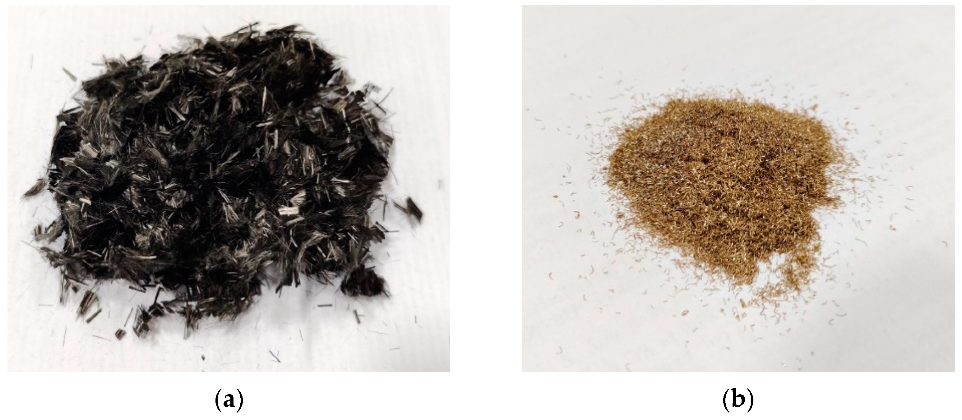
To ascertain the flexural behaviour of the sustainable RCC beam, an experimental investigation was carried out. The self-sensing mortar layer was applied to the bottom of the beam to determine the failure of the beam through the self-sensing effect of the smart mortar.

2.1. Materials

The beam specimen was created using M30 concrete. The mix ratio for the M30 grade of concrete used for the beam specimen is shown in Table 1; the RCC beam’s design and its reinforcing details were determined from the guidelines of IS 456-2000 [43]. The primary bars at the bottom were two numbers of 12 mm-diameter bars. The top reinforcement was made up of two numbers of 10 mm-diameter bars. Stirrups with a 100-mm centre-to-centre spacing were made of two-legged, 6-mm-diameter rods. Locally accessible river sand, OPC 53-grade cement, coarse aggregate measuring 12.5 mm, and portable water were used to create the RCC beams.
The smart mortar layer was made up of OPC 53-grade cement, locally available river sand of particle size less than 600 µm, potable water, and brass fibres of randomly varying length from 1 mm to 4 mm, with diameters varying from 0.1 mm to 1 mm (manufacturer: Sarda Industries Pvt. Ltd, Jaipur, Rajasthan, India). Carbon fibres of size 5 mm in length with a diameter of 10 µm were also used (manufacturer: Fibre Region Pvt. Ltd., Chennai, India). The pictorial representation of brass and carbon fibres is shown in Figure 1. A superplasticizer was used to improve the workability of the mortar mixture. Methyl cellulose (manufacturer: Southern India scientific Corporation Pvt. Ltd., Chennai, India) was additionally used for improving the dispersion of carbon fibres when carbon fibre was added to the cement mortar mixture. Silica fume (manufacturer: Astrra chemicals Pvt, Ltd., Chennai, India) was added to the smart mortar mixture to improve its strength. The fibres were randomly mixed to the mortar matrix. Modified MM 7.5 masonry mortar was adopted for smart mortar strips conforming to IS 2250-1981 [44]. The mix proportions along with the constituents are shown in Table 2.
In addition to the materials listed in Table 1, methylcellulose was added to the cement mortar mix at a rate of 1.872 kg/m3 for the hybrid brass addition. The brass fibres were added at a dosage of 0.25% by the volume of the mortar. In the hybrid brass-carbon fibre addition, the fibres were added in a combination of 95% brass fibre and 5% carbon fibre. Carbon fibres were added at a rate of 0.24% by volume of mortar.

2.2. Casting of Specimen
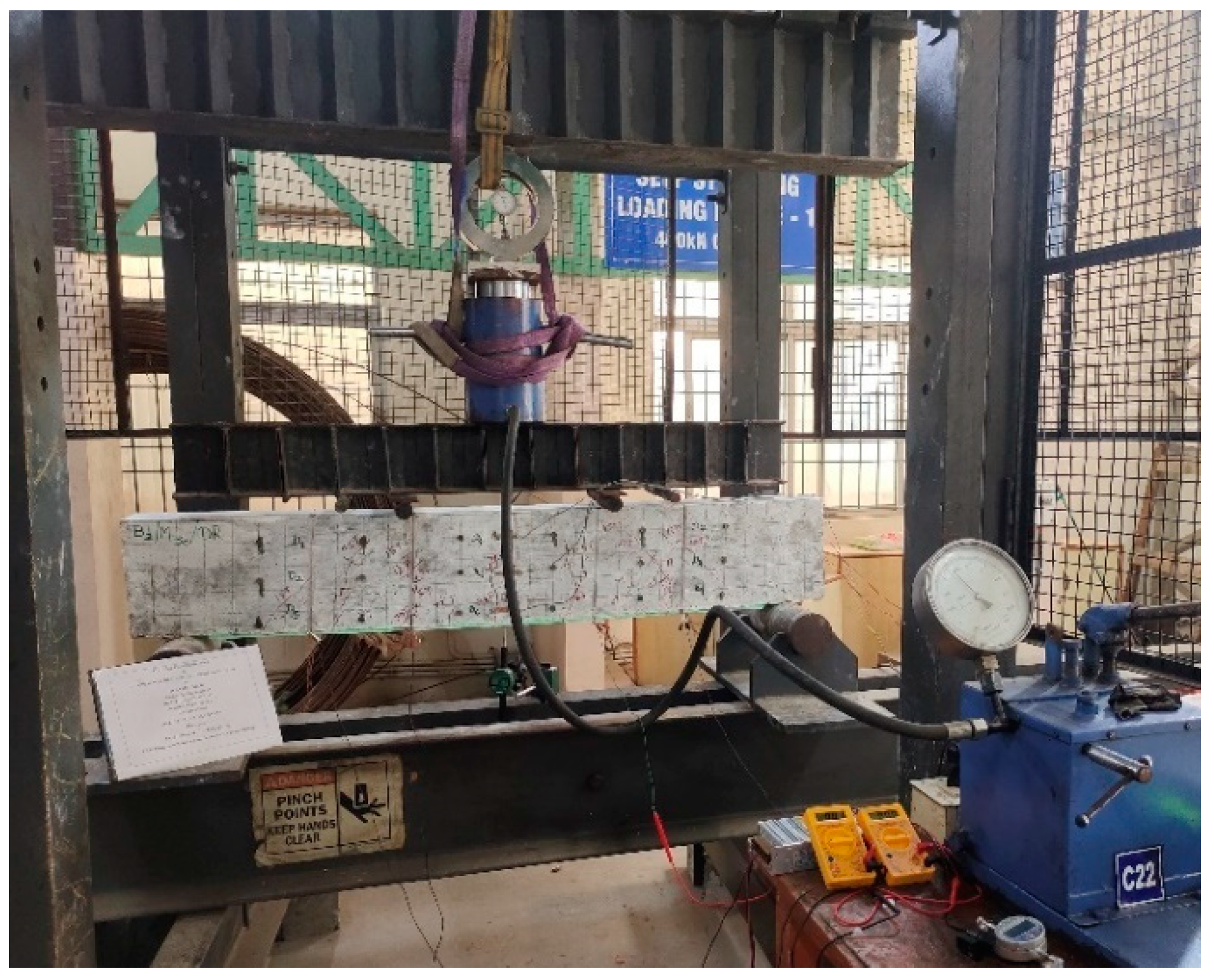
Six beam specimens, measuring 1500 mm in length, 100 mm in width, and 250 mm in depth, were cast. The beams were designed by IS 456-2000 [43]. Two numbers of 12 mm steel bars were placed longitudinally at the bottom of the test beams, and two numbers of 10 mm steel bars were placed longitudinally at the top of the test beams as the tensile and compressive steel reinforcement, respectively. Two-legged stirrups of 6 mm diameter were used at 100 mm centre-to-centre spacing.
Two mortar layers were cast separately with dimensions of 1200 mm in length, 100 mm in width, and 6 mm in thickness. One mortar strip was made of brass fibre addition, while the other was made of hybrid brass–carbon fibre addition. These two mortar strips were pasted to the RCC beam with Araldite paste at the bottom. In the other two beam specimens, the freshly prepared mortar paste was applied to the existing beam, which was manufactured 28 days earlier. In the other two beam specimens, the mortar layer was freshly cast on the beam during the time of its manufacture. Detailed information on the beam specimens is given in Table 3.

2.3. Test Method

The flexural behaviour of the beam was determined with the two-point method (loading frame manufacturer–SRM Institute of Science and Technology) of loading. Six beams with a smart mortar layer were tested with two-point loading. To measure the deflections, one deflectometer was positioned at the beam’s midspan at the bottom. The dimensions of the beam with the smart mortar layer are illustrated in Figure 2. To measure the strains, three strain gauges were attached at the top, middle, and bottom of the beam.
As depicted in Figure 3, the specimens were tested in a 400 kN loading frame. Using a load cell, the beam specimens were subjected to incremental loading until failure. The electrical measurements of the RCC beam were determined using the four-probe method. Silver paint was applied to the specimen at four points with intervals of 200 mm, as shown in Figure 4. Steel wires were wound along the applied silver paint to determine the flow of electricity across the specimen. Two multimeters were connected to the four probes, along with a DC power supply. Through the multimeter, the voltage and current readings were recorded. Using the voltage and current data that were obtained, the resistance and fractional change in electrical resistance were calculated. Under two-point loading, the load was applied in an increment of 5 kN. Readings were recorded using digital multimeters, a deflectometer, and strain gauges. The fractional change in electrical resistance (fcr) was determined using the resistivity value for each load increment of 5 kN.

3. Discussion and Findings

3.1. A New Brass Fibre Added Mortar Layer Is Cast on a New 1.5-m-Long Beam

The ultimate load of fresh brass fibre added to the mortar layer cast on a fresh beam was observed at 145 kN. The stress observed at the bottom of the beam was higher when compared to the middle and top of the beam. At the initial stages of loading, the strain observed in the reinforced beam was minimal. As the loading was increased and the first crack was observed, the strain at the bottom increased gradually until failure. Figure 5 illustrates that, when the loading increased, flexural cracks developed in every reinforced concrete beam. From the beginning point of loading until failure, a progressive increase in the mid-span displacement of the beam was also noticed. The graphical representations of stress versus strain, fcr versus strain, load versus displacement, and load versus fcr are shown in Figure 6. The maximum bottom strain at failure was observed as 0.00131 for the brass fibre-added fresh mortar layer cast on a fresh concrete beam of length 1.5 m.
The fcr values were calculated with the current and voltage readings recorded through the multimeter connected to the beam through the four-probe winding method. The fractional change in electrical resistivity values was found to steadily increase with the initial increase in loading through the four-probe winding method. The fractional change in electrical resistivity values was found to steadily increase with the initial increase in loading. Whereas, when the loading was about to reach the failure load, a drastic change in the fractional change in electrical resistivity values was observed. This was caused by the formation and development of more cracks in the mortar layer.
Similarly, the fractional change in electrical resistivity values decreased when the applied load approached the failure load and was at its minimum at the ultimate load. This occurred due to the splitting of the mortar layer at the bottom of the beam through the development of cracks in it. The electrical circuit formed through the four probes was disconnected by the breakage of the smart mortar layer, leading to the reduction in fcr values. The pictorial representation of the crack formed on the smart mortar layer at the bottom of the beam is shown in Figure 7.

3.2. A Fresh Mortar Layer of Brass Fibres Was Cast on an Existing 1.5-m-Long Beam

The ultimate load of the freshly added brass fibre mortar layer cast on an existing beam was measured at 140 kN. The behaviour of the beam with respect to displacement, strain, and stress was similar to that of a fresh mortar layer with added brass fibres cast on a fresh beam. When compared to a fresh brass fibre added mortar layer cast on a new beam, a fresh brass fibre added mortar layer cast on an existing beam reduced displacement by 20.37%. Similarly, fcr increased by 4.26% in a fresh brass fibre-added mortar layer cast on an existing beam when compared to a fresh brass fibre-added mortar layer cast on a fresh beam.
The failure of the smart mortar layer was caused by the formation and propagation of flexural cracks on the beam, which led to the disconnection of the self-sensing effect [27]. The maximum bottom strain at failure was observed as 0.00525 for the brass fibre-added fresh mortar layer cast on an existing concrete beam of length 1.5 m. The graphical representation of stress versus strain, fcr versus strain, load versus displacement, and load versus fcr is shown in Figure 8.

3.3. Brass Fibre Added Mortar Layer Pasted on Existing Beam of Length 1.5 m with Araldite Paste

The final load of the brass fiber-added mortar layer cast and placed on the existing beam with the help of Araldite paste was 155 kN. The behaviour of the beam in terms of displacement, strain, and stress was identical to a fresh brass fibre mortar layer cast on a fresh beam. The displacement was reduced by 8.71% when brass fibre was added to the mortar layer placed on the existing beam with the help of Araldite paste as compared to a fresh mortar layer placed on a fresh beam. The electrical resistance improved by 15.43% more when brass fibre was added to the mortar layer placed on the existing beam with the help of Araldite paste as compared to a fresh mortar layer cast on a fresh beam. The addition of a smart mortar layer to the existing RCC beam with Araldite paste improved the piezoelectricity of the beam greatly. This is due to the improved bonding between the beam and the smart mortar layer due to the Araldite paste. Hence, among all three methods used to implement the smart mortar on the reinforced concrete fibre-added mortar layer cast on the existing beam with the help of Araldite paste, one was observed to be more effective.
The development and spread of flexural cracks on the beam caused the self-sensing effect to be disconnected, which resulted in the failure of the smart mortar layer. The maximum bottom strain at failure was observed as 0.00234 for the brass fibre-added mortar layer pasted on the existing concrete beam of length 1.5 m with Araldite paste. In Figure 9, the relationships between stress and strain, fcr and strain, load and displacement, and load and fcr are represented graphically.

3.4. Hybrid Brass Carbon Fresh Mortar Layer Cast on a Fresh Concrete Beam of Length 1.5 m

The ultimate load of the mortar layer added with fresh hybrid brass-carbon fibre cast on a fresh beam was measured at 140 kN. In comparison to the centre and top of the beam, there was more strain towards the bottom of the beam. The reinforced beam experienced very little strain during the early stages of loading. When the loads were increased, the bottom strain progressively developed until failure, and the first crack was observed. The mid-span displacement of the beam was also found to significantly increase from the point of initial loading until failure.
The fcr values were calculated using voltage and current readings from a multimeter connected to the beam via the four-probe winding method. It was discovered that, initially, the fcr values increased continuously with the increase in loading. In contrast, a sharp change in the fcr values was seen as the loading approached the failure load. This was carried on by the formation and growth of further cracks in the layer of mortar.
The fcr values also decreased as the applied load approached the failure load and were at their lowest at the maximum load. This happened as a result of the cracks in the smart mortar layer that developed at the bottom of the beam. The fracturing of the smart mortar layer interrupted the electrical circuit established by the four probes, which reduced the fcr values. In Figure 10, the relationships between stress and strain, fcr and strain, load and displacement, and load and fcr are represented graphically.
When compared to a fresh brass fibre added mortar layer cast on a fresh beam, the displacement in a fresh hybrid brass–carbon fibre-added mortar layer cast on a fresh beam increased by 3.04%. Similarly, when compared to a fresh brass fibre added mortar layer cast on a fresh beam, the fractional change in electrical resistivity decreased by 14.76% in a fresh hybrid brass and carbon fibre added mortar layer cast on a fresh beam. The maximum bottom strain at failure was observed as 0.00136 for the hybrid brass carbon fibre-added fresh mortar layer cast on a fresh concrete beam of length 1.5 m.

3.5. Hybrid Brass–Carbon Fibre Added Fresh Mortar Layer Cast on an Existing Concrete Beam of Length 1.5 m

The peak load of the fresh hybrid brass–carbon fibre-added mortar layer cast on an existing beam was 130 kN. The beam behaved similarly to a fresh hybrid brass–carbon fibre-added mortar layer cast on a fresh beam in terms of displacement, strain, and stress. When fresh hybrid brass with a carbon fibre added mortar layer cast on an existing beam was compared to fresh hybrid brass with a carbon fibre added mortar layer cast on a new beam, displacement was reduced by 15.94%. When comparing fresh hybrid brass with a carbon fibre-added mortar layer cast on a fresh beam to fresh hybrid brass with a carbon fibre-added mortar layer cast on an existing beam, the electrical resistivity increased by 6.62%.
In comparison to a fresh brass fibre-added mortar layer cast on an existing beam, the displacement in a fresh hybrid brass–carbon fibre-added mortar layer cast on an existing beam increased by 8.77%. Similarly, when compared to a fresh brass fibre-added mortar layer cast on an existing beam, the fcr of a fresh hybrid brass and carbon fibre added mortar layer cast on an existing beam decreased by 12.83%. The maximum bottom strain at failure was observed as 0.00455 for the hybrid brass–carbon fibre-added fresh mortar layer cast on an existing concrete beam of length 1.5 m. The graphical representation of stress versus strain, fcr versus strain, load versus displacement, and load fcr is shown in Figure 11.

3.6. Hybrid Brass–Carbon Fibre-Added Mortar Layer Pasted on Existing Concrete Beam with Araldite Paste of Length 1.5 m

The ultimate load of the hybrid brass-carbon fibre mortar layer placed on the existing beam with the help of Araldite paste was 150 kN. The beam behaved in the same manner as the fresh hybrid brass–carbon fibre-added mortar layer cast on a fresh beam in terms of displacement, strain, and stress. In comparison to fresh hybrid brass with carbon fibre added mortar applied to a new beam, displacement was reduced by 11.16% in the hybrid brass, with carbon fibre-added mortar layer applied to an existing beam using Araldite paste. In comparison to a hybrid brass–carbon fibre-added fresh mortar layer cast on a fresh beam, the electrical resistance increased by 15.51% when the hybrid brass–carbon fibre-added fresh mortar layer was placed on an existing beam with the aid of Araldite paste.
When compared to the brass fibre added mortar layer placed on the existing beam with the help of Araldite paste, the displacement increased by 0.27% in the hybrid brass and carbon fibre added mortar layer placed on the existing beam with the help of Araldite paste. Similarly, in the brass fibre-added mortar layer placed on an existing beam with the help of Araldite paste, the fcr decreased by 14.70% in the hybrid brass–carbon fibre-added mortar layer placed on an existing beam with the aid of Araldite paste. The maximum bottom strain at failure was observed as 0.00156 for the hybrid brass–carbonfibre-added mortar layer pasted on an existing concrete beam of length 1.5 m with Araldite paste. The graphical representation of stress versus strain, fcr versus strain, load versus displacement, and load versus fcr is shown in Figure 12.
The load was applied with a 2 kN increment in UTM. A strain gauge and digital multimeter were used for testing. The fractional change in electrical resistance (fcr) was determined using the resistivity value for each 2 kN increment in load.

4. Discussion of Results

From the experimental results, it was found that the fractional change in the electrical resistivity values was found to steadily increase with the increase in loading initially. In contrast, a drastic reduction in the fractional change in electrical resistivity values was observed when the loading approached the failure load. Both brass and carbon fibres performed well as conductive fillers in the production of cement composites that helped to measure strains on the surface of a structural member, irrespective of the local stresses being in tension or in compression, which was similar to the experimental observations of Baeza et al. [27]. The most sensitive dosage of brass fibres in the mortar strip was 0.25% (by volume of the mortar). Similarly, the optimum dosages of the hybrid brass-carbon fibre were 95% for brass fibres and 5% for carbon fibres, respectively (by volume of the mortar) [30].
The ultimate load at failure was also observed in a separately cast, fibre-added mortar layer pasted to the existing beam with the use of Araldite paste. Compared to the hybrid brass–carbon fibre-added mortar layer, the brass fibre-added mortar layer’s fractional change in electrical resistivity performance improved by 14–18%. Similarly, the ultimate load at failure was improved by 3–8% when the brass fibre was added to the mortar layer as compared to the hybrid brass-carbon fibre-added mortar layer.
From the experimental results presented in this paper, it was found that the addition of brass fibre and hybrid brass–carbon fibre made mortar more self-sensing. With the newly developed smart mortar, the strain level in any flexural member can be assessed. Additionally, the load level on the beam or on the slab can be assessed by measuring the electrical resistance of the member. The structural elements can maintain their load level within a safe limit. The developed smart mortar can be used for structural applications where temperature changes are severe, such as chemical storage facilities, pavements, dams, bridges, and for tall buildings. A quick, affordable, and less time-consuming technique of monitoring the structural health of a building is possible by the development of this smart mortar layer that can be applied to an existing structural member to monitor its performance throughout its lifecycle.

5. Conclusions

The following findings were obtained from experiments on reinforced concrete beams with smart mortar layers containing either pure brass fibre or a hybrid of brass and carbon fibre. By adding a smart mortar layer to the bottom of a reinforced concrete beam, the electrical resistivity values were able to detect a failure in the beam before it actually occurred, making the beam element more sustainable. The application of Araldite paste, which improves bonding and piezoelectricity, is the most effective method for implementing the smart mortar layer in the reinforced concrete beam. The brass fibre-added smart mortar performed better when compared to the hybrid brass–carbon fibre-added smart mortar in terms of piezoresistive effect. The behaviour of the beam in terms of displacement, strain, and the ultimate load was more or less similar, since all the beams were prepared with the same materials and specifications. The formation and progression of cracks in the smart mortar layer before the failure of the beam resulted in prior intimation through a sudden drop in a fractional change in electrical resistivity values. The ultimate load at failure was observed in a separately cast fibre-added mortar layer pasted to the existing beam with the use of Araldite paste. Compared to the hybrid brass–carbon fibre-added mortar layer, the brass fibre-added mortar layer showed an increase in the electrical resistivity values by 14–18%. Similarly, the ultimate load at failure was improved by 3–8% in the case of brass fibre-added mortar layer when compared to the case of hybrid brass–carbon fibre-added mortar layer.
As a result, structural members can be coated with either carbon or brass fibres in thin mortar layers to detect damage to the member. It can also be used to detect damage in members before they fail and collapse, making the structure more sustainable. Further research can be carried out with different conductive fillers in the mortar matrix. Studies on the applications of such smart mortars in high-rise buildings, pavements, and dams can also be carried out. The incorporation of smart mortars into other structural elements subjected to cyclic loading can be performed in the future.

Author Contributions

R.D.: Conducted the experiments; T.V. and S.K.S.: Supervised the research as well as the Validation of results; R.D., T.V. and S.K.S.: Introduced the idea of self-sensing in this project, wrote, reviewed, and submitted the paper, and collaborated in and coordinated the research; T.V., S.K.S., B.G.A.G. and K.R.: Suggested and chose the journal for submission; R.D., T.V., S.K.S., B.G.A.G. and K.R.: Participated in the manuscript revision phase. All authors have read and agreed to the published version of the manuscript.

Funding

This research received no external funding.

Data Availability Statement

The data presented in this study are available on request from the corresponding author.

Acknowledgments

The authors acknowledge SRMIST, Kattankulathur for their support in conducting this research study.

Conflicts of Interest

This manuscript has not been submitted to, nor is it under review by, another journal or other publishing venue. The authors have no affiliation with any organization with a direct or indirect financial interest in the subject matter discussed in the manuscript. The authors declare no conflict of interest.

References

  1. Arya, C.; Clarke, J.L.; Kay, E.A.; O’Regan, P.D. Design guidance for strengthening concrete structures using fiber composite materials: A review. Eng. Struct. 2001, 24, 889–900. [Google Scholar] [CrossRef]
  2. Gao, B.; Kim, J.K.; Leung, C.K.Y. Experimental investigation of taper ended FRP strips in FRP strengthened RC beams. In Proceedings of the 4th International Conference on Advanced Composite Materials in Bridges and Structures, Calgary, AB, Canada, 20–23 July 2004. [Google Scholar]
  3. Khalifa, A.; Nanni, A. Rehabilitation of rectangular simply supported RC beams with shear deficiencies using CFRP composites. Constr. Build. Mater. 2002, 16, 135–146. [Google Scholar] [CrossRef]
  4. Pesic, N.; Pilakoutas, K. Concrete beams with externally bonded flexural FRP-reinforcement: Analytical investigation of debonding failure. Compos. Part B Eng. 2003, 34, 327–338. [Google Scholar] [CrossRef] [Green Version]
  5. Mohammad Noh, N. Effectiveness of RC Beams Strengthened with Near Surface Mounted (NSM) Fiber Reinforced Polymer (FRP) Bars and Externally Bonded (EB) FRP Sheets. Master’s Thesis, Universiti Teknologi MARA, Shah Alam, Malaysia, 2003. [Google Scholar]
  6. Gao, B.; Kim, J.K.; Leung, C.K.Y. Optimization of tapered end design for FRP strips bonded to RC beams. Compos. Sci. Technol. 2005, 66, 1266–1273. [Google Scholar] [CrossRef]
  7. Ceroni, F.; Pecce, M.; Mattys, S.; Taerwe, L. Debonding strength and anchorage devices for reinforced concrete elements strengthened with FRP sheets. Compos. Part B Eng. 2007, 30, 429–441. [Google Scholar] [CrossRef]
  8. Xiong, G.J.; Jiang, X.; Liu, J.W.; Chen, L. A way for preventing tension delamination of concrete cover in midspan of FRP strengthened beams. Constr. Build. Mater. 2005, 21, 402–408. [Google Scholar] [CrossRef]
  9. Al-Saidy, A.H.; Al-Harthy, A.S.; Al-Jabri, K.S.; Abdul-Halim, M.; Al Shidi, N.M. Structural performance of corroded RC beams repaired with CFRP sheets. Compos. Struct. 2010, 92, 1931–1938. [Google Scholar] [CrossRef]
  10. El-Ghandour, A.A. Experimental and analytical of CFRP flexural and shear strengthening efficiencies of RC beams. Constr. Build. Mater. 2011, 25, 1419–1429. [Google Scholar] [CrossRef]
  11. Buyle-Bodin, F. Use of carbon fiber textile to control premature failure of reinforced concrete beams strengthened with bonded CFRP plates. J. Ind. Text. 2010, 33, 145–157. [Google Scholar] [CrossRef]
  12. Arafah, A.M. Factors affecting the reliability of reinforced concrete beams. WIT Trans. Ecol. Environ. 2000, 45, 379–387. [Google Scholar]
  13. Khalel, R.I. Torsional behavior of high-strength reinforced concrete beams. J. Eng. Sustain. Dev. 2013, 17, 317–332. [Google Scholar]
  14. Jagana, R.; Kumar, C.V. High strength concrete. Int. J. Eng. Sci. Res. Technol. 2017, 6, 394–407. [Google Scholar]
  15. Rashid, M.A.; Mansur, M.A. Reinforced high-strength concrete beams in flexure. ACI Struct. J. 2005, 102, 462. [Google Scholar]
  16. Fu, X.; Ma, E.; Chung, D.D.L.; Anderson, W.A. Self-monitoring in carbon fiber reinforced mortar by reactance measurement. Cem. Concr. Res. 1997, 27, 845–852. [Google Scholar] [CrossRef]
  17. Fu, X.; Chung, D.D.L. Effect of curing age on the self-monitoring behavior of carbon fiber reinforced mortar. Cem. Concr. Res. 1997, 27, 1313–1318. [Google Scholar] [CrossRef]
  18. Chung, D.D.L. Self-monitoring structural materials. Mater. Sci. Eng. 1998, 22, 57–78. [Google Scholar] [CrossRef]
  19. Teomete, E.; Kocyigit, O.I. Tensile strain sensitivity of steel fiber reinforced cement matrix composites tested by split tensile test. Constr. Build. Mater. 2013, 47, 962–968. [Google Scholar] [CrossRef]
  20. Teomete, E. Transverse strain sensitivity of steel fiber reinforced cement composites tested by compression and split tensile tests. Constr. Build. Mater. 2014, 55, 136–145. [Google Scholar] [CrossRef]
  21. Teomete, E. Measurement of crack length sensitivity and strain gage factor of carbon fiber reinforced cement matrix composites. Measurement 2015, 74, 21–30. [Google Scholar] [CrossRef]
  22. Teomete, E. The effect of temperature and moisture on electrical resistance, strain sensitivity and crack sensitivity of steel fiber reinforced smart cement composite. Smart Mater. Struct. 2016, 25, 075024. [Google Scholar] [CrossRef]
  23. Han, B.; Zhang, K.; Yu, X.; Kwon, E.; Jinping, O.U. Nickel particle based self-sensing pavement for vehicle detection. Measurement 2011, 44, 1645–1650. [Google Scholar] [CrossRef]
  24. Han, B.; Yu, Y.; Han, B.Z.; Ou, J.P. Development of a wireless stress/strain measurement system integrated with pressure-sensitive nickel powder-filled cement-based sensors. Sens. Actuators A 2008, 147, 536–543. [Google Scholar] [CrossRef]
  25. Han, B.; Han, B.Z.; Ou, J.P. Experimental study on use of nickel powder-filled Portland cement-based composite for fabrication of piezoresistive sensors with high sensitivity. Sens. Actuators A 2009, 149, 51–55. [Google Scholar] [CrossRef]
  26. Sun, M.; Liew, R.J.Y.; Zhang, M.H.; Li, W. Development of cement-based strain sensor for health monitoring of ultra-high strength concrete. Constr. Build. Mater. 2014, 65, 630–637. [Google Scholar] [CrossRef]
  27. Baeza, F.J.; Galao, O.; Zornoza, E.; Garcés, P. Multifunctional cement composites strain and damage sensors applied on reinforced concrete (RC) structural elements. Materials 2013, 6, 841–855. [Google Scholar] [CrossRef] [Green Version]
  28. Xiao, H.; Li, H.; Ou, J.P. Strain sensing properties of cement-based sensors embedded at various stress zones in a bending concrete beam. Sens. Actuators A 2011, 167, 581–587. [Google Scholar] [CrossRef]
  29. Kumar, D.R.; Thirumurugan, V.; Satyanarayanan, K.S. Experimental study on optimization of smart mortar with the addition of brass fibres. Mater. Today Proc. 2021, 50, 388–393. [Google Scholar] [CrossRef]
  30. Durairaj, R.; Varatharajan, T.; Srinivasan, S.K.; Gurupatham, B.G.A.; Roy, K. An Experimental Study on Electrical Properties of Self-Sensing Mortar. J. Compos. Sci. 2022, 6, 208. [Google Scholar] [CrossRef]
  31. Sevim, O.; Jiang, Z.; Ozbulut, O.E. Effects of graphene nanoplatelets type on self-sensing properties of cement mortar composites. Constr. Build. Mater. 2022, 359, 129488. [Google Scholar] [CrossRef]
  32. Erman, D.; Egemen, T. Cross tension and compression loading and large-scale testing of strain and damage sensing smart concrete. Constr. Build. Mater. 2022, 316, 125784. [Google Scholar]
  33. Cheng, A.; Lin, W.-T. Electrical resistance and self-sensing properties of pressure-sensitive materials with graphite filler in Kuralon fiber concrete. Mater. Sci. 2022, 40, 223–239. [Google Scholar] [CrossRef]
  34. Dong, W.; Li, W. Application of intrinsic self-sensing cement-based sensor for traffic detection of human motion and vehicle speed. Constr. Build. Mater. 2022, 355, 129130. [Google Scholar] [CrossRef]
  35. Bellic, A.; Mobili, A. Commercial and recycled carbon/steel fibers for fiber-reinforced cement mortars with high electrical conductivity overlay panel. Cem. Concr. Compos. 2020, 109, 103569. [Google Scholar] [CrossRef]
  36. Zhao, J.; Wang, K.; Wang, S.; Wang, Z.; Yang, Z.; Shumuye, E.D.; Gong, X. Effect of Elevated Temperature on Mechanical Properties of High-Volume Fly Ash-Based Geopolymer Concrete, Mortar and Paste Cured at Room Temperature. Polymers 2021, 13, 1473. [Google Scholar] [CrossRef]
  37. Tucci, F.; Vedernikov, A. Design Criteria for Pultruded Structural Elements. Encycl. Mater. Compos. 2021, 3, 51–68. [Google Scholar]
  38. Vedernikov, A.; Safonov, A.; Tucci, F.; Carlone, P.; Akhatov, I. Analysis of Spring-in Deformation in L-shaped Profiles Pultruded at Different Pulling Speeds: Mathematical Simulation and Experimental Results. In Proceedings of the ESAFORM 2021, 4th International ESAFORM Conference on Material Forming, Liège, Belgium, 14–16 April 2021. [Google Scholar]
  39. Minchenkov, K.; Vedernikov, A. Effects of the quality of pre-consolidated materials on the mechanical properties and morphology of thermoplastic pultruded flat laminates. Compos. Commun. 2022, 35, 101281. [Google Scholar] [CrossRef]
  40. Zhou, P.; Li, C. Durability study on the interlaminar shear behavior of glass-fibre reinforced polypropylene (GFRPP) bars for marine applications. Constr. Build. Mater. 2022, 349, 128694. [Google Scholar] [CrossRef]
  41. Madenci, E.; Özkılıç, Y.O.; Aksoylu, C.; Safonov, A. The Effects of Eccentric Web Openings on the Compressive Performance of Pultruded GFRP Boxes Wrapped with GFRP and CFRP Sheets. Polymers 2022, 14, 4567. [Google Scholar] [CrossRef]
  42. Ozkilic, Y.O.; Gemi, L.; Madenci, E.; Aksoylu, C.; Kalkan, İ. Effect of the GFRP wrapping on the shear and bending Behavior of RC beams with GFRP encasement. Steel Compos. Struct. 2022, 45, 193–204. [Google Scholar]
  43. IS 456-2000; Indian Standard Plain and Reinforced Concrete Code of Practice. Bureau of Indian Standards: New Delhi, India, 2000.
  44. IS 2250-1981; Indian Standard Code of Practice for Preparation and Use of Masonry Mortars. Bureau of Indian Standards: New Delhi, India, 1981.
Figure 1. The pictorial representation of brass and carbon fibres. (a) Carbon fibre. (b) Brass fibre.
Jcs 07 00132 g001
Figure 2. Pictorial representation of beam with smart mortar layer.
Jcs 07 00132 g002
Figure 3. Test setup of the beam with smart mortar layer.
Jcs 07 00132 g003
Figure 4. Four–probe method with wire winding on smart mortar.
Jcs 07 00132 g004
Figure 5. Crack patterns of the reinforced concrete beam with smart mortar layer.
Jcs 07 00132 g005
Figure 6. Graphical representation of (a) stress vs. strain, (b) fcr vs. strain, (c) load vs. displacement and (d) load versus fcr behaviour of the brass fibre added fresh mortar layer cast on fresh concrete beam of length 1.5 m.
Jcs 07 00132 g006aJcs 07 00132 g006b
Figure 7. Failure modes of the smart mortar layer.
Jcs 07 00132 g007
Figure 8. Graphical representation of (a) stress vs. strain, (b) fcr vs. strain, (c) load vs. displacement, and (d) load versus fcr behaviour of the brass fibre added fresh mortar layer cast on an existing concrete beam of length 1.5 m.
Jcs 07 00132 g008aJcs 07 00132 g008b
Figure 9. Graphical representation of (a) stress vs. strain, (b) fcr vs. strain, (c) load vs. displacement and (d) load versus fcr behaviour of brass fibre added mortar layer pasted on existing concrete beam with Araldite paste of length 1.5 m.
Jcs 07 00132 g009aJcs 07 00132 g009b
Figure 10. Graphical representation of (a) stress vs. strain, (b) fcr vs. strain, (c) load vs. displacement, and (d) load versus fcr behaviour of hybrid brass carbon fibre added fresh mortar layer cast on a fresh concrete beam of length 1.5 m.
Jcs 07 00132 g010aJcs 07 00132 g010b
Figure 11. Graphical representation of (a) stress vs. strain, (b) fcr vs. strain, (c) load vs. displacement, and (d) load versus fcr behaviour of hybrid brass–carbon fibre-added fresh mortar layer cast on an existing concrete beam of length 1.5 m.
Jcs 07 00132 g011aJcs 07 00132 g011b
Figure 12. Graphical representation of (a) stress vs. strain, (b) fcr vs. strain, (c) load vs. displacement, and (d) load versus fcr behaviour of hybrid brass–carbon fibre-added mortar layer pasted on existing concrete beam with Araldite paste of length 1.5 m.
Jcs 07 00132 g012aJcs 07 00132 g012b
Table 1. Mix design for M30 grade concrete.
Cement (kg/m3)Fine Aggregate (kg/m3)Coarse Aggregate (kg/m3)Water (kg/m3)
428.48888.94924.64171.39
Table 2. Mix proportion and constituents for mortar strips.
Cement (kg/m3)Fine Aggregate (kg/m3)Water (kg/m3)Superplasticizer (kg/m3)Silica Fume (kg/m3)
4681427.52347.0270.20
Table 3. Details of the beam specimens.
S. No.BeamVariations Provided
1Beam-1-FB-FM-BFBy incorporating brass fibres into the mortar mixture, a fresh mortar layer was cast on a fresh beam.
2Beam-2-EB-FM-BFBy including brass fibres in the mortar mixture, a fresh mortar layer was cast on the top of the existing beam.
3Beam-3-EB-EM-BFBrass fibres were included in the mortar mixture, and a separate layer of cast mortar was placed over the existing beam.
4Beam-4-FB-FM-HBCBy incorporating hybrid brass carbon fibres into the mortar mixture, a fresh mortar layer was cast on a fresh beam.
5Beam-5-EB-FM-HBCHybrid brass-carbon fibres are added to the mortar mixture before casting a new mortar layer over an existing beam.
6Beam-6-EB-EM-HBCHybrid brass carbon fibres were added to the mortar mixture, and a separate layer of cast mortar was applied to the existing beam with Araldite paste.
Disclaimer/Publisher’s Note: The statements, opinions and data contained in all publications are solely those of the individual author(s) and contributor(s) and not of MDPI and/or the editor(s). MDPI and/or the editor(s) disclaim responsibility for any injury to people or property resulting from any ideas, methods, instructions or products referred to in the content.

