
Cool-Clave—An Energy Efficient Autoclave


Abstract
:1. Introduction
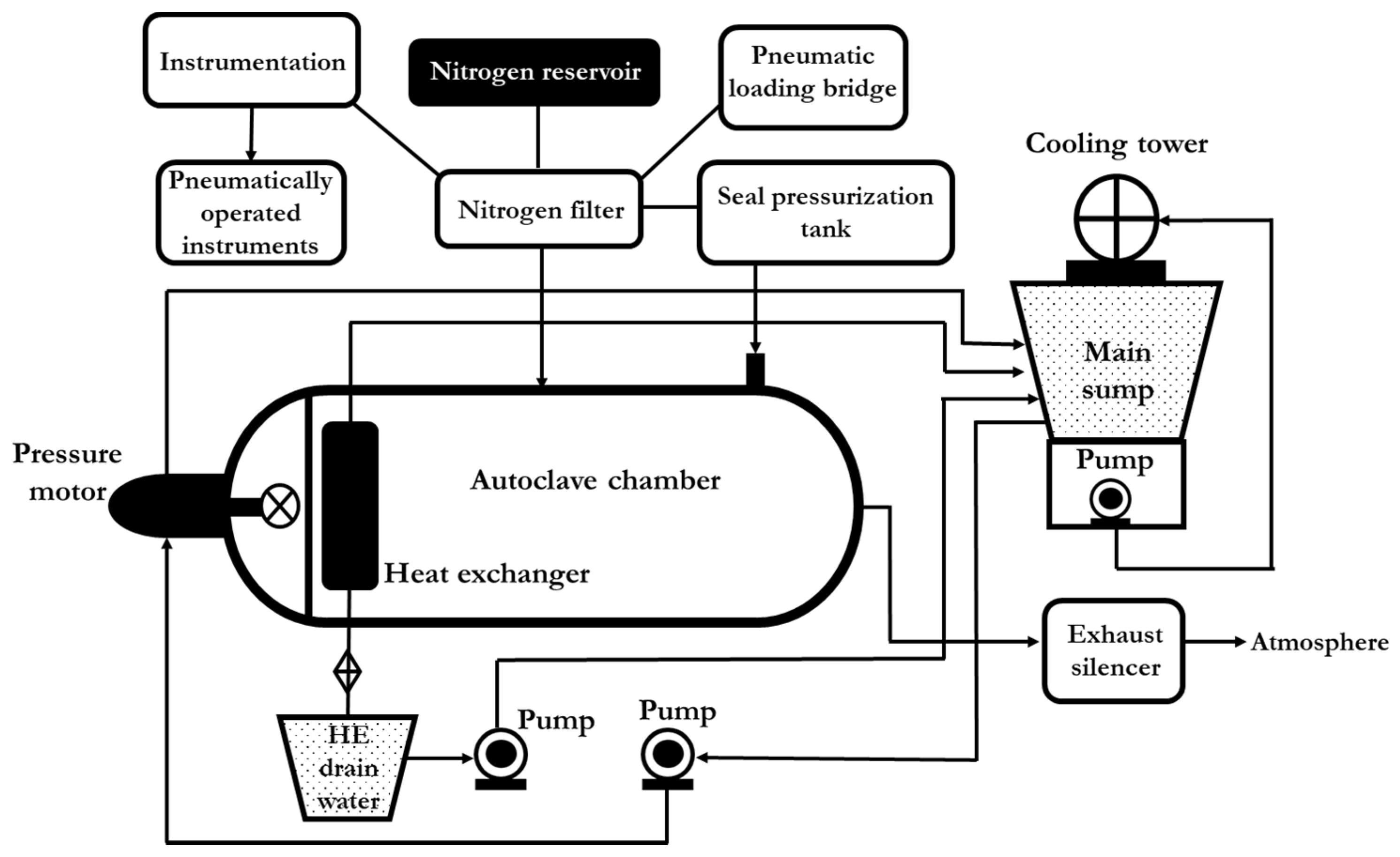
2. Autoclave
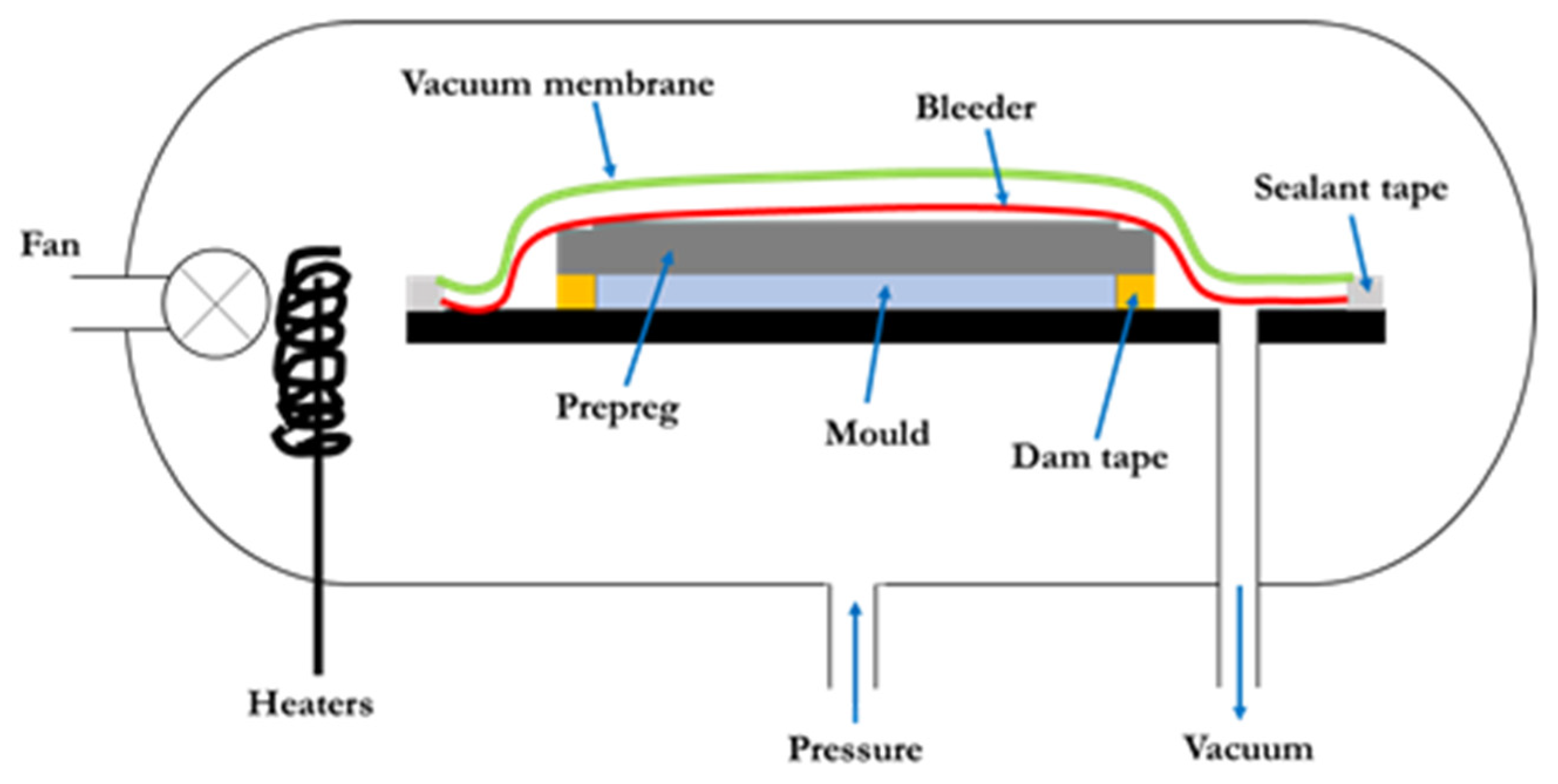
2.1. Autoclave Moulding
- (a)
- Applicable to both thermosetting and thermoplastic fibre-reinforced composites
- (b)
- Facilitates better inter-layer adhesion
- (c)
- Enables good fibre wetting
- (d)
- Enables higher uniformity in composite solidification
- (e)
- Supports superior fibre volume fraction in composite component
- (f)
- Reduced void content in the composite due to the vacuum/pressure
- (g)
- Facilitates manufacturing composite parts with high strength-to-weight ratio
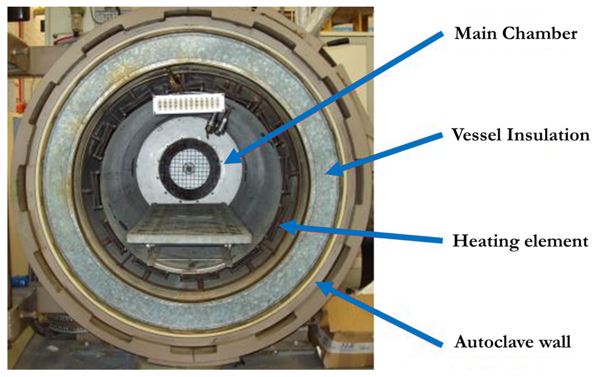
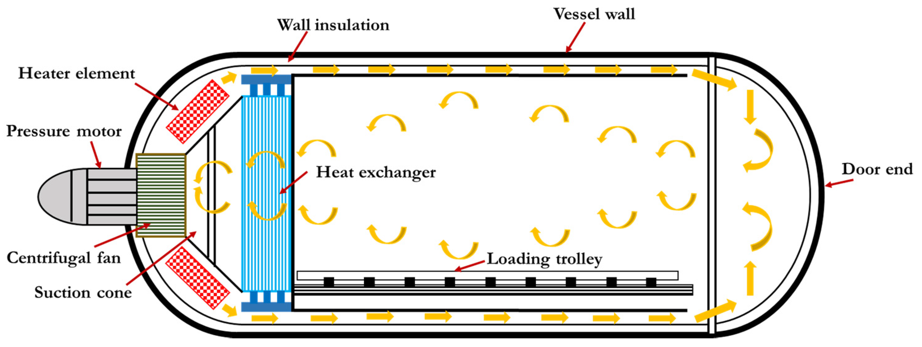
2.2. Heating and Air-Circulation System in an Autoclave
2.3. Pressurization and Cooling System
2.4. Vacuum System
2.5. Loading System
2.6. Electrical and Control System
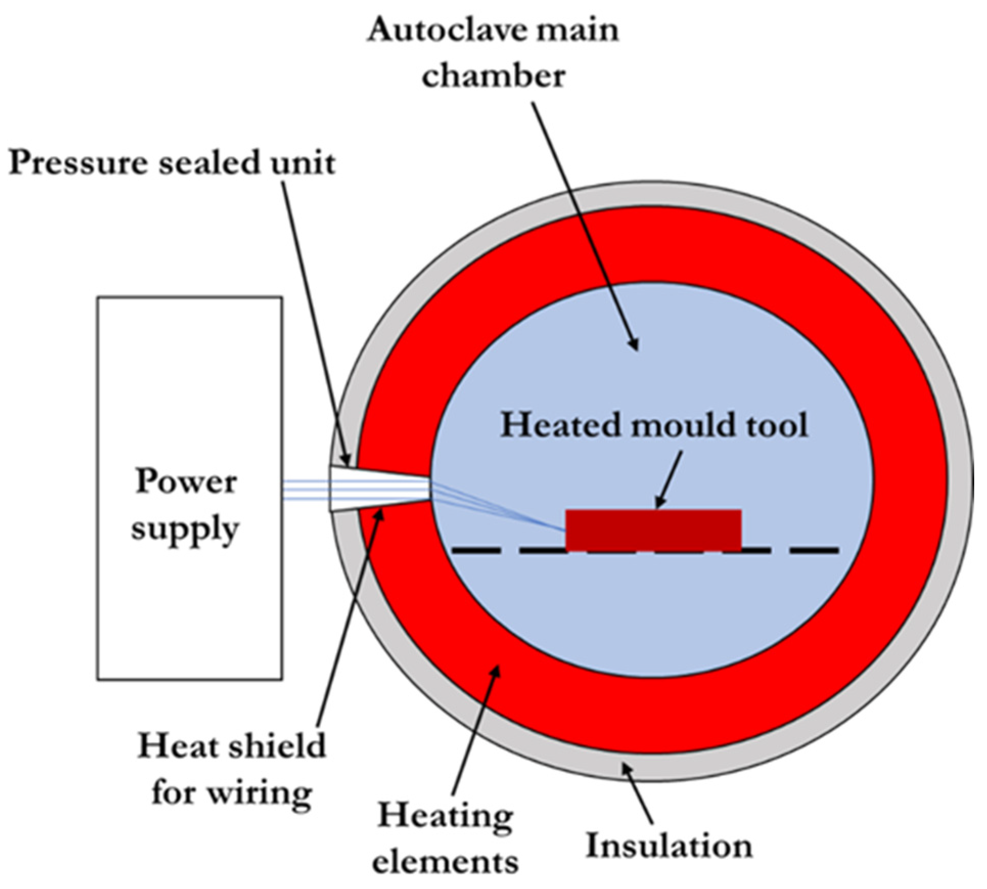
3. Cool-Clave Technique
- pressure vessel (autoclave)
- heated mould tool and control unit
- efficient thermal insulation of the bagged component
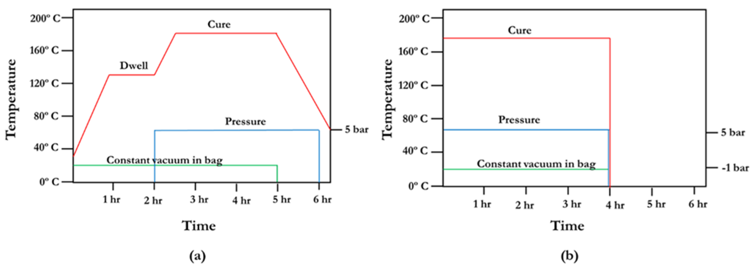
3.1. Analysis of Energy Consumption between a Traditional Autoclave and Cool-Clave Technique
- heat from room temperature (20 °C) up to 80 °C
- pressurisation of autoclave at 80 °C to 0.7 MPa (gauge)
- reheat to 80 °C to compensate for the temperature drop during pressurisation
- hold temperature for 30 min
- heat from 80 °C up to 130 °C
- hold temperature for 95 min
- load the autoclave after the dwell period
- higher productivity
- optimise profit potential
- cure multiple components with different temperatures and cycle times
- increase in the potential of new innovative products
- less energy required for the process, a possibility of the use of clean energy
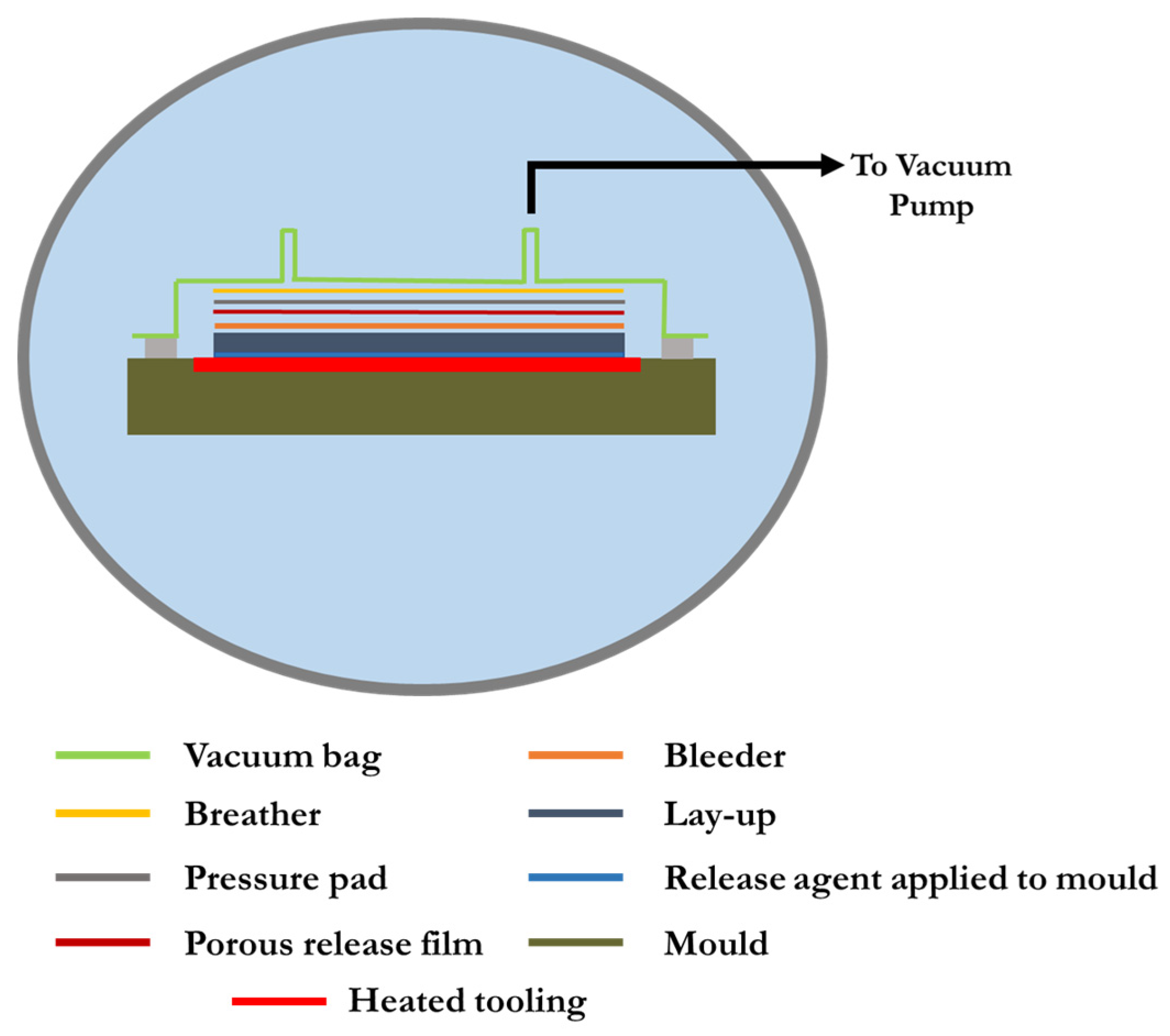
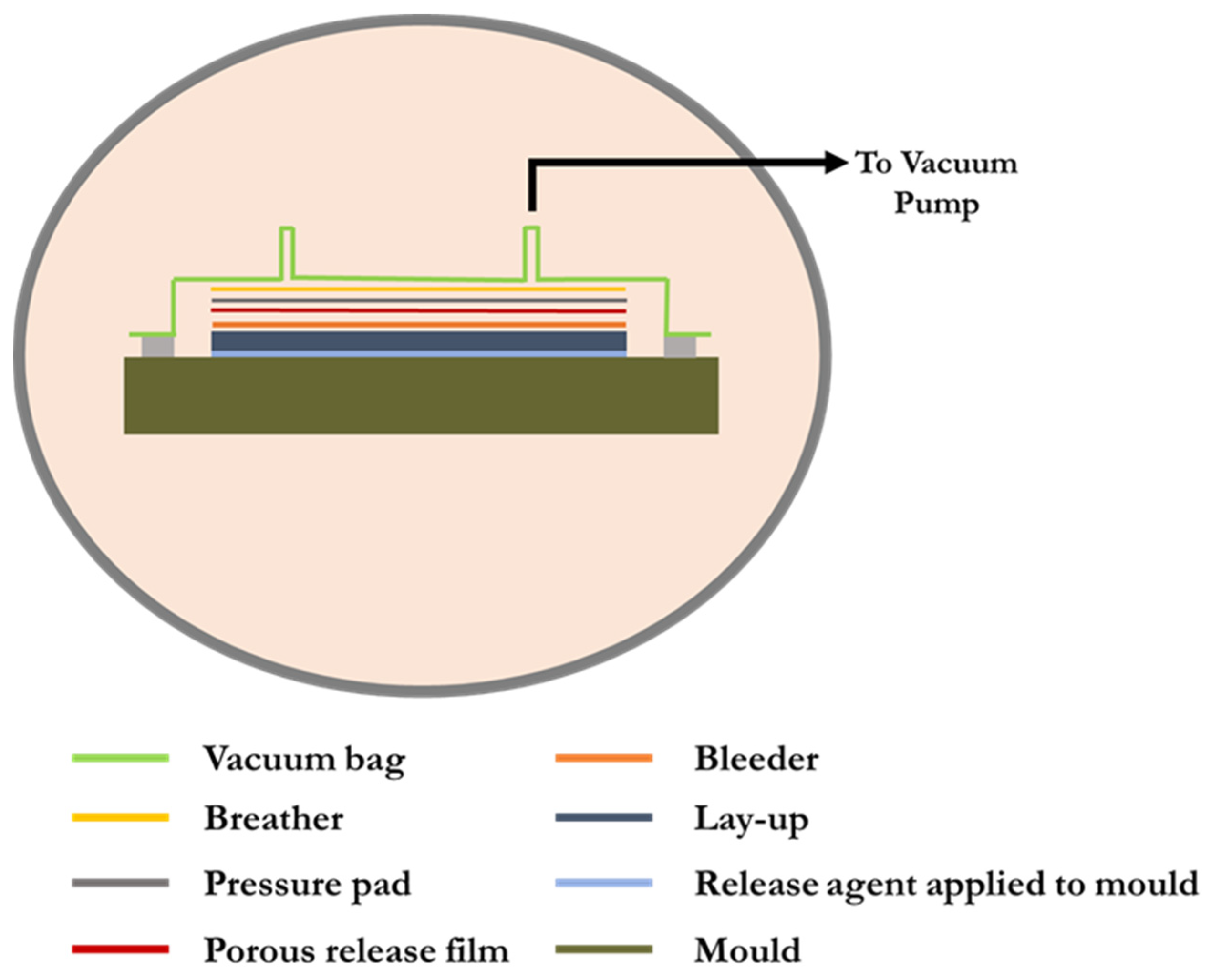
3.2. Consolidating Resin-Infused Laminates inside Autoclave
Improved Autoclave Process for Resin-Infused Laminates
4. Conclusions
Author Contributions
Funding
Institutional Review Board Statement
Informed Consent Statement
Data Availability Statement
Conflicts of Interest
References
- Mahmood, A.S.; Summerscales, J.; James, M.N. Resin-rich volumes (RRV) and the performance of fibre-reinforced composites: A review. J. Compos. Sci. 2022, 6, 53. [Google Scholar] [CrossRef]
- Summerscales, J. Fibre Distribution and the Process-Property Dilemma. In The Structural Integrity of Carbon Fibre Composites: Fifty Years of Progress and Achievement; Beaumont, P.W.R., Soutis, C., Eds.; Springer: Berlin/Heidelberg, Germany, 2016; pp. 301–317. [Google Scholar]
- Centea, T.; Grunenfelder, L.K.; Nutt, S.R. A review of out-of-autoclave prepregs—Material properties, process phenomena, and manufacturing considerations. Compos. A 2015, 70, 132–154. [Google Scholar] [CrossRef]
- Okunzuwa, A.E.; Anjum, N.; Eze, V.O.; Okoli, O.I. A Review on the Out-of-Autoclave Process for Composite Manufacturing. J. Compos. Sci. 2022, 6, 172–202. [Google Scholar]
- Solan, J. Out-of-Autoclave Processing for Aero Use, Composites World Supplement, 2016. Available online: https://www.compositesworld.com/articles/february-supplement-out-of-autoclave-processing-for-aero-applications (accessed on 29 December 2022).
- Arney, M.; Grove, S.M.; Progoulakis, I.; Searle, T.; Short, D.; Spooner, J.; Summerscales, J. Integrally Heated Tooling for the Manufacture of Fibre-Reinforced Composites. In Proceedings of the Conference ‘Composites Processing 2004’, CPA, Bromsgrove, UK, 28–30 April 2004. [Google Scholar]
- Williams, C.D.; Summerscales, J.; Grove, S.M. Resin Infusion under Flexible Tooling (RIFT): A review. Compos. A 1996, 27, 517–524. [Google Scholar] [CrossRef]
- Summerscales, J.; Searle, T.J. Low pressure (vacuum infusion) techniques for moulding large composite structures. Proc IMechE Part L J. Mater. Des. Appl. 2005, 219, 45–58. [Google Scholar] [CrossRef]
- Summerscales, J. Resin Infusion Under Flexible Tooling (RIFT). In Encyclopedia of Composites, 2nd ed.; Nicolais, L., Borzacchiello, A., Eds.; John Wiley & Sons: Hoboken, NJ, USA, 2012; pp. 2648–2658. [Google Scholar]
- Fox, B.L.; Herring, M.L. The effect of a rapid curing process on the surface finish of a carbon fibre epoxy composite. Compos. B 2011, 42, 1035–1043. [Google Scholar]
- Bogetti, T.A.; Gillespie, J.W. Two-Dimensional Cure Simulation of Thick Thermosetting Composites. J. Compos. Mater. 1991, 25, 239–273. [Google Scholar] [CrossRef]
- Summerscales, J. Taking the high energy demand out of autoclave processing of composites. In Proceedings of the SAMPE European Conference, Southampton, UK, 11–13 September 2018. [Google Scholar]
- Dayananda, G.N.; Subba Rao, M.; Somashekar, B.R. Indigenous development of autoclave technology. In Proceedings of the National Symposium on Development in Advanced Composites and Structures, Hyderabad, India, 17 September 1994. [Google Scholar]
- Advani, S.G.; Sozer, E.M. Processing advanced thermoset fiber composites. In Process Modelling in Composites Manufacturing; Marcel Dekker: New York, NY, USA, 2002; pp. 339–343. [Google Scholar]
- Monaghan, M.R.; Mallon, P.J. Development of a computer-controlled autoclave for forming thermoplastic composites. Compos. Manuf. 1990, 1, 8–14. [Google Scholar] [CrossRef]
- Stratton, P.F.; Groome, D.G. BOC gases, enhanced safety in advanced polymer composite curing autoclaves. In Proceedings of the 42nd International SAMPE Symposium and Exhibition, Anaheim, CA, USA, 4–8 May 1997; pp. 172–180. [Google Scholar]
- Upadhya, A.R.; Dayananda, G.N.; Kamalakannan, G.M.; Setty, J.R.; Daniel, J.C. Autoclaves for Aerospace Applications: Issues and Challenges. Int. J. Aerosp. Eng. 2011, 2011, 1–11. [Google Scholar] [CrossRef]
- Prudham, G. Development of Cool Clave Processing Method. Bachelor’s Thesis, University of Plymouth, Plymouth, UK, 2010. [Google Scholar]
- Kamalakannan, G.M.; Rao, M.S. Development of a computer-based process control system for an autoclave to cure polymer matrix composites. In Proceedings of the International Conference on Instrumentation, Pune, India, 19–21 December 2004. [Google Scholar]
- Alam, P. Composites Engineering: An A-Z Guide; IOP Publishing: Bristol, UK, 2021. [Google Scholar]
- Eckold, G. Design and Manufacture of Composite Structures; Woodhead Publishing: Cambridge, UK, 1994. [Google Scholar]
- Fernandez, I.; Blas, F.; Frovel, M. Autoclave forming of thermoplastic composite parts. J. Mater. Process. Technol. 2003, 143–144, 266–290. [Google Scholar] [CrossRef]
- Dhakal, H.M.; Ismail, S.O. Design, manufacturing processes and their effects on bio-composite properties. In Sustainable Composites for Lightweight Applications; Dhakal, H.M., Ismail, S.O., Eds.; Series in Composites Science and Engineering; Woodhead Publishing: Sawston, UK, 2021; pp. 121–177. [Google Scholar]
- Gupta, M.; Jain, A.; Kamineni, J.N.; Burela, R.G. Advances and applications of biofiber-based polymer composites. In Advances in Bio-Based Fiber; Rangappa, S.M., Puttegowda, M., Parameswaranpillai, J., Siengchin, S., Gorbatyuk, S., Eds.; Woodhead Publishing: Sawston, UK, 2022; pp. 575–602. [Google Scholar]
- Kamalakannan, G.M.; Gupta, A.K. An improved technique and its implementation for control of high-power heaters in large autoclaves and similar plants. In Proceedings of the International Conference of Instrumentation, Pune, India, 17–19 December 2009. [Google Scholar]
- Kamalakannan, G.M. Ethernet based online process monitoring and controlling of a plant having RS-232 or RS-485 equipment. In Proceedings of the National Symposium on Instrumentation, NSI-32, Erode, India, 24–26 October 2007. [Google Scholar]
- Prudham, G.; Summerscales, J. Cost reduction in autoclave processing I: Heated tooling and cool air pressurisation. In Proceedings of the 13th International Conference on Flow Processing in Composite Materials, Tokyo, Japan, 6–9 July 2016. [Google Scholar]
- Grove, S.M.; Progoulakis, I.; Searle, T.J.; Summerscales, J.; Healey, P. Heated Tooling for Aerospace Composites Manufacture. SAMPE J. 2005, 41, 36–45. [Google Scholar]
- Snow, J.C. Thermal Analysis of Composites Manufacture in the Autoclave with Heated Tooling and Cool Air Pressurisation. Bachelor’s Thesis, University of Plymouth, Plymouth, UK, 2018. [Google Scholar]
- Ciriscioli, P.R.; Springer, G.S. Smart Autoclave Cure of Composites; Technomic Publishing Company: Lancaster, PA, USA, 1990. [Google Scholar]
- Lewin, G. The Influence of Resin Rich Volumes (RRV) on Composite Mechanical Properties. Bachelor’s Thesis, University of Plymouth, Plymouth, UK, 2016. [Google Scholar]
- Stringer, L.G. Optimization of the wet lay-up/vacuum bag process for the fabrication of carbon fibre epoxy composites with high fibre fraction and low void content. Composites 1989, 20, 441–452. [Google Scholar] [CrossRef]
- Wilkinson, R. Enhancing the Mechanical Properties of A Resin Infused Composite Using Autoclave Consolidation. Bachelor’s Thesis, University of Plymouth, Plymouth, UK, 2017. [Google Scholar]


| Phase | Start Temperature (°C) | Final Temperature (°C) | Energy Consumed (kJ) |
|---|---|---|---|
| 1 | 20 | 80 | 157.5 |
| 2 | 80 | 27.7 | 0 |
| 3 | 27.7 | 80 | 1061 |
| 4 | 80 | 80 | 306.4 |
| 5 | 80 | 130 | 1014.2 |
| 6 | 130 | 130 | 1081.2 |
| Total energy consumed | 3620.3 | ||
| Property | Units | Laminates | ||||
|---|---|---|---|---|---|---|
| A | B | C | D | E | ||
| Process | Hand lay-up | RIFT II | RIFT II | RIFT II | Autoclave | |
| Net pressure | MPa | 0 | 0.03 | 0.06 | 0.09 | 0.586 |
| Plate thickness | mm | 2.34 ± 0.06 | 2.09 ± 0.04 | 2.03 ± 0.05 | 1.94 ± 0.02 | 1.93 ± 0.03 |
| Vf (thickness) | % | 40.8 | 45.7 | 47.0 | 49.3 | 49.6 |
| Vf (burn-off) | % | 42.0 | 46.5 | 46.7 | 48.1 | 50.9 |
| Young’s modulus | GPa | 21.9 ± 0.6 | 23.7 ± 0.3 | 24.5 ± 0.6 | 24.9 ± 0.4 | 25.0 ± 0.2 |
| Flex. modulus 40 mm span | GPa | 18.7 ± 0.4 | 19.8 ± 0.5 | 19.8 ± 0.5 | 21.1 ± 0.5 | 22.4 ± 0.4 |
| Flex. modulus 48 mm span | GPa | 17.3 ± 0.2 | 19.0 ± 0.3 | 18.8 ± 1.0 | 20.4 ± 0.3 | 20.9 ± 0.7 |
| Tensile strength | MPa | 384 ± 15 | 416 ± 20 | 426 ± 26 | 452 ± 31 | 478 ± 24 |
| Flexural strength | MPa | 558 ± 7 | 578 ± 13 | 586 ± 11 | 599 ± 21 | 608 ± 13 |
| ILSS 10.0 mm span | MPa | 56.4 ± 0.8 | 53.5 ± 1.3 | 54.1 ± 1.4 | 53.4 ± 1.6 | 52.5 ± 1.1 |
| ILSS 11.4 mm span | MPa | 52.5 ± 1.7 | 49.9 ± 1.7 | 51.2 ± 0.6 | 46.6 ± 0.9 | 48.7 ± 1.0 |
| SBV area | % | 1.9 | 2.4 | 1.4 | 0.3 | 0.02 |
| Property | Units | Infusion | 3.1/0.0 | 5.9/0.0 | 5.9/39.5 | 5.9/45 | 5.9/48.3 |
|---|---|---|---|---|---|---|---|
| Ext. pressure | MPa | 0.0 | 3.1 × 10⁻⁴ | 5.9 × 10⁻⁴ | 5.9 × 10⁻⁴ | 5.9 × 10⁻⁴ | 5.9 × 10⁻⁴ |
| Dwell time | min | 0.0 | 0.0 | 0.0 | 39.5 | 45 | 48.3 |
| Plate thickness | μm | 2040 ± 51 | 1890 ± 3 | 1780 ± 16 | 1880 ± 1 | 1930 ± 11 | 1980 ± 1 |
| Vf (thickness) | % | 51.9 ± 1 | 56.1 ± 0.1 | 59.3 ± 0.5 | 56.3 ± 0.0 | 54.7 ± 0.3 | 53.6 ± 0.0 |
| Vf (burn-off) | % | 52.3 | 56.4 | 60.9 | 56.7 | 54.3 | 52.4 |
| Flexural modulus | GPa | 20.5 ± 0.4 | 25.6 ± 0.9 | 28.4 ± 0.9 | 26.4 ± 0.7 | 25.4 ± 0.5 | 24.0 ± 1.0 |
| Flexural strength | MPa | 347 ± 14 | 384 ± 16 | 415 ± 20 | 391 ± 14 | 383 ± 10 | 364 ± 12 |
| ILSS | MPa | 41.0 ± 1.9 | 44.5 ± 2.5 | 41.5 ± 2.5 | 42.5 ± 3.4 | 43.2 ± 1.8 | 42.4 ± 1.7 |
Disclaimer/Publisher’s Note: The statements, opinions and data contained in all publications are solely those of the individual author(s) and contributor(s) and not of MDPI and/or the editor(s). MDPI and/or the editor(s) disclaim responsibility for any injury to people or property resulting from any ideas, methods, instructions or products referred to in the content. |
© 2023 by the authors. Licensee MDPI, Basel, Switzerland. This article is an open access article distributed under the terms and conditions of the Creative Commons Attribution (CC BY) license (https://creativecommons.org/licenses/by/4.0/).
Share and Cite
Chowdhury, I.R.; Summerscales, J. Cool-Clave—An Energy Efficient Autoclave. J. Compos. Sci. 2023, 7, 82. https://doi.org/10.3390/jcs7020082
Chowdhury IR, Summerscales J. Cool-Clave—An Energy Efficient Autoclave. Journal of Composites Science. 2023; 7(2):82. https://doi.org/10.3390/jcs7020082
Chicago/Turabian StyleChowdhury, Indraneel R., and John Summerscales. 2023. "Cool-Clave—An Energy Efficient Autoclave" Journal of Composites Science 7, no. 2: 82. https://doi.org/10.3390/jcs7020082
APA StyleChowdhury, I. R., & Summerscales, J. (2023). Cool-Clave—An Energy Efficient Autoclave. Journal of Composites Science, 7(2), 82. https://doi.org/10.3390/jcs7020082